Kondo Kagaku T125003 Remote Control Transmitter User Manual manual 1 26
Kondo Kagaku Co., Ltd. Remote Control Transmitter manual 1 26
UserManual.wiki
>
Kondo Kagaku
>
T125003 User Manual
>
manual 1 26
Contents
1.
manual 52 78
2.
manual 1 26
3.
manual 27 51
manual 1 26
Navigation menu
Upload a User Manual
Namespaces
Wiki Guide
HTML
PDF
Info
Views
User Manual
Discussion / Help
Navigation
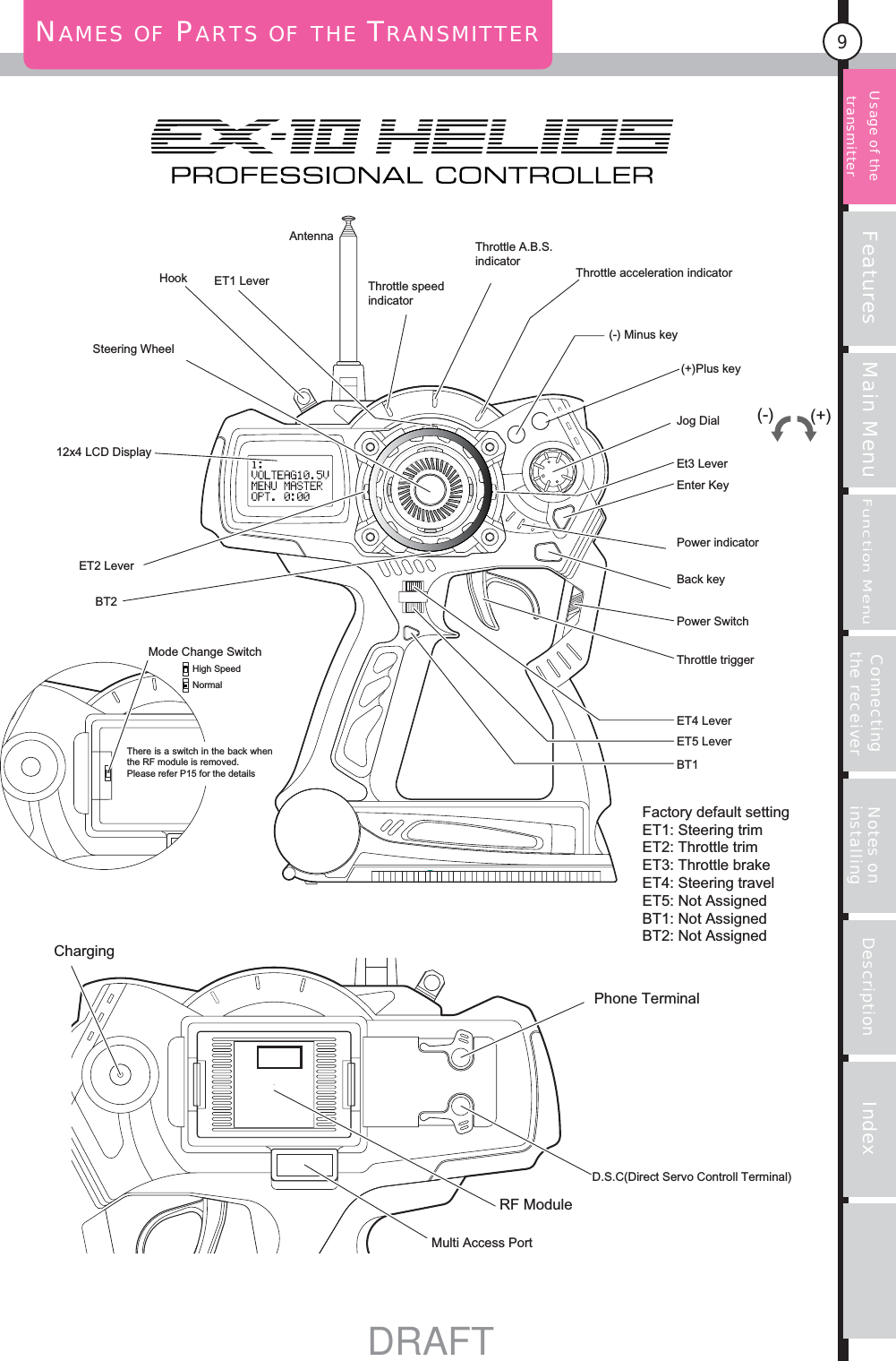
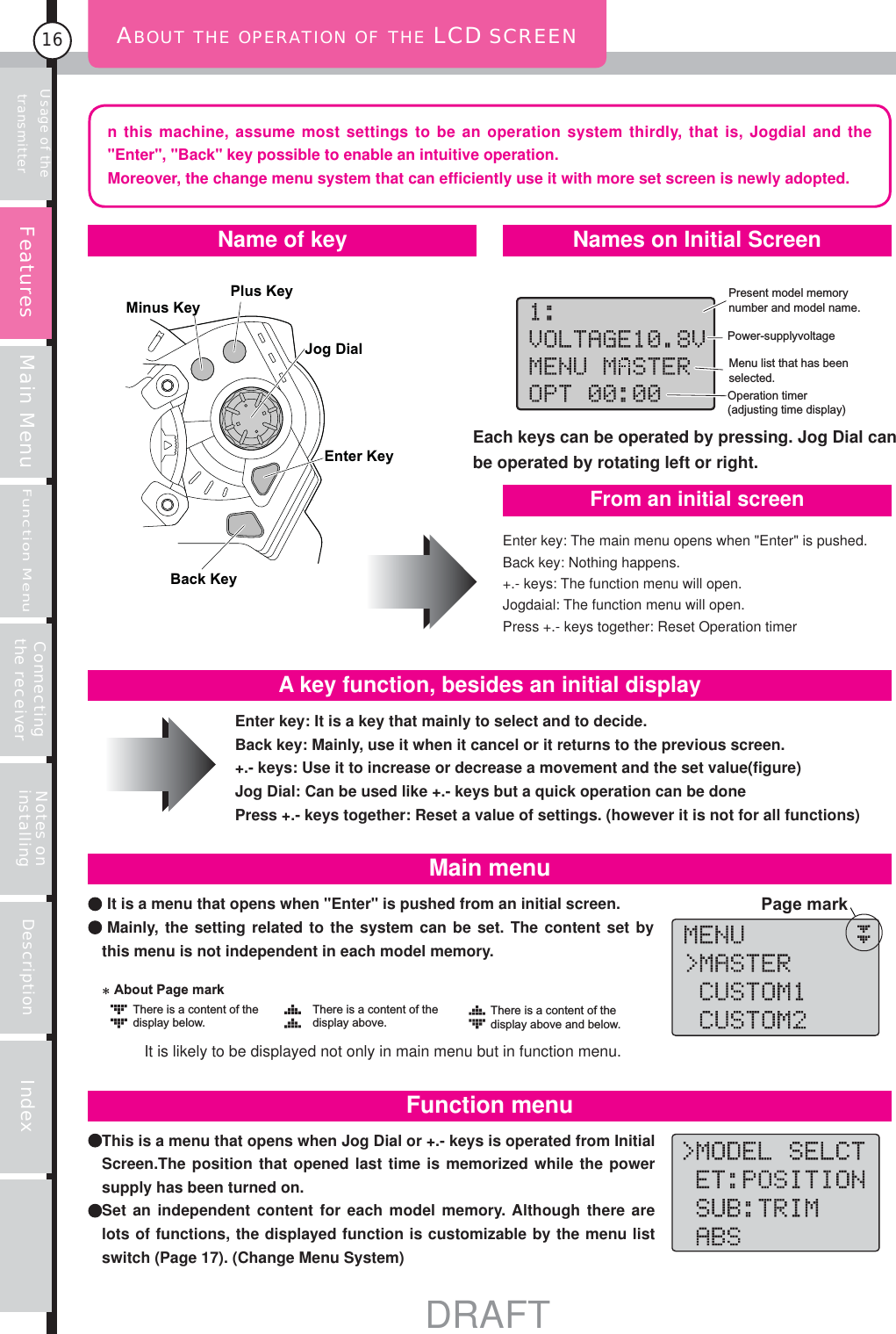
![Features Main MenuFunction MenuConnecting the receiver Notes on installing Description Index14Insert dry cells or battery pack into the transmitter (P12)Be sure to charge battery pack before use.How to Use Transmitter-1PreparationSwitching the Power Onadvice Other than MASTWER, it can be changed to CUSTOM 1 or CUSTOM 2 which you can change display items by yourself.Change the menu list of initial screen that it is displayed when Jog Dial or (+), (-) keys are operated.Change the setting of POWER ALARM of the main menu. At shipment from factory the alarm will sounds when the unit does not operate for more than 3 minutes.The buzzer sounds if it doesn't operate it for a long time. I want to change this setting. Open the function menu and perform SET UP.Change function assignment of ET lever or BT button.Use Mode Switch (detach RF module from main body) and CH.SELECT of function menu (P57).Change operation mode of response. Change settings of operations.Open the main menu and then open the BUZZER from OPTION to set up.Want to change pitch of the buzzer beep or change the melody.(The backlight is [Auto] at factory default.)Open the main menu and then open the BACK LIGHT from OPTION to set up.Changing the setting of the backlight of the LCD.Open the main menu and then open the CONTRAST from OPTION to adjust.In case of LCD contrast is too blight or too dark.P28P31P29P30Usage of the transmitter Changing the display or settings.A blue power indicator at the right of the main body lights when the power of the transmitter is on and the LCD display is displayed with the start sound.The battery will last long if crystal is pulled out or the RF module is detached when only the transmitter is operated.Moreover, when only the transmitter is operated when the management of the band is done in the course etc. , it is similar. (Please refer P20 D.S.C page)Reference pageReference pageP29Reference pageP19Reference pageP60Reference pageP28Reference pageP17Reference page](https://usermanual.wiki/Kondo-Kagaku/T125003.manual-1-26/User-Guide-348594-Page-14.png)