Kondo Kagaku T125003 Remote Control Transmitter User Manual manual 1 26
Kondo Kagaku Co., Ltd. Remote Control Transmitter manual 1 26
Contents
- 1. manual 52 78
- 2. manual 1 26
- 3. manual 27 51
manual 1 26


Usage of the
transmitter Features Main Menu
Function Menu
Connecting
the receiver Notes on
installing Description Index
3
Read First
READ FIRST
It is illegal to reproduce the contents of this manual without permission.
The contents of this manual are subject to future changes without notice.
Although every effort has been made to ensure the accuracy of the information
contained in this manual, please contact us if you have any questions or if you fi nd
any errors.
We cannot assume any responsibility for any damages arising from the use of
1,These products are only for the control of models.
2,If the products are exported from Japan, the prior approval of the Ministry of
Radio/Telecommunications is required regarding the country of destination. If these
products are re-exported from other countries, it may be subject to restrictions on
such re-export and prior approval of government authorities may be required
3,KO is not responsible for any use of this product that is not in compliance with
applicable laws and disclaims all responsibility for any modifi cation or alteration of
the product.
Other notes
Notes on application, exportation and modifi cation of the products.
Please understand the basic uses of "How to use the transmitter".
In addition, please locate the item in the main menu and the function menu to master each
function.
Please see "Feature" pages to fi nd out about the new additional functions.
Here is an explanation of the new functions.
LCD screen and key operation (P16)
Change menu (P17)
Indicator and warnings (P18)
Response mode (P19)
D.S.C (Direct Servo Control) (P20)
Multi access port (P21)
Data pack (P22)
Trim and sub trim (P23)
Wheel tension adjustment, phone terminal (P24)
How to fi nd information in this manual
Thank you for purchasing the EX-10 Helios. Read this manual carefully in order
to obtain maximum performance from the unit. Keep this manual handy.
DRAF
T

Usage of the
transmitter Features Main Menu
Function Menu
Connecting
the receiver Notes on
installing Description Index
4
CONTENTS
Read first 03
Contents 04 05
Notes on safe usage 06 07 08
Names of parts of the transmitter 09
LCD Screen table Main menu 10
LCD Screen table Function menu 11
How to insert batteries and such 12 13
How to use transmitter 14 15
LCD Screen and key operation 16
Change menu 17
Indicator and warnings 18
Response mode 19
D.S.C(Direct Servo Controll) 20
Multi access port 21
Data pack 22
Trim and sub trim 23
Steering tention adjustment,wheel extention,phone terminal 24
Response Mode Compatibility Table 25
Usage of the transmitter
Features
Main Menu
Change menu 26
Add menu 26
Delete menu 27
Move menu 27
Power alarm 28
Option menu 28
Format 29
Option menu LCD contrast 29
Option menu Set buzzer Buzzer tone 29
Option menu Set buzzer Alarm buzzer 29
Option menu Set buzzer Custome tone 30
Option menu Back light 31
D
RAF
T

Usage of the
transmitter Features Main Menu
Function Menu
Connecting
the receiver Notes on
installing Description Index
5
CONTENTS
Function Menu
Model select
ET Position auto display
Sub trim
A.B.S (Acrive Brake System)
Throttle speed
Throttle punch
Throttle curve
Throttle brake
Throttle high point
Throttle preset
Throttle acceleration
Steering speed
Steering punch
Steering curve
Steering balance
Steering travel
Automatic start
Model copy
Model name
Memory reset (model clear)
Adjust volume
Channel select
Reverse switch
Trim rate
Set up
Up timer
Down timer
Lap timer
32
33
34
35 36
37 38
39
40
41
42
43
44 45
46 47
48
49
50
51
52
53
54
55
56
57
58
59
60
61
62
63
Connecting the reaciever
Notes on installing
Specfications
Description
Index
Repair
Guarantee
64 65
66 67 68
69
70 71
72 73
74
75
Usage of the
transmitter Features Main Menu
Function Menu
Connecting
the receiver Notes on
installing Description Index
6
FOR THE SAFE USAGE OF THIS UNIT-1
For the safe Usage of this Unit
With the nature of radio controlled models, misoperation will
result in danger. In order to avoid these circumstances and to
use this unit safely, please read the contents thoroughly.
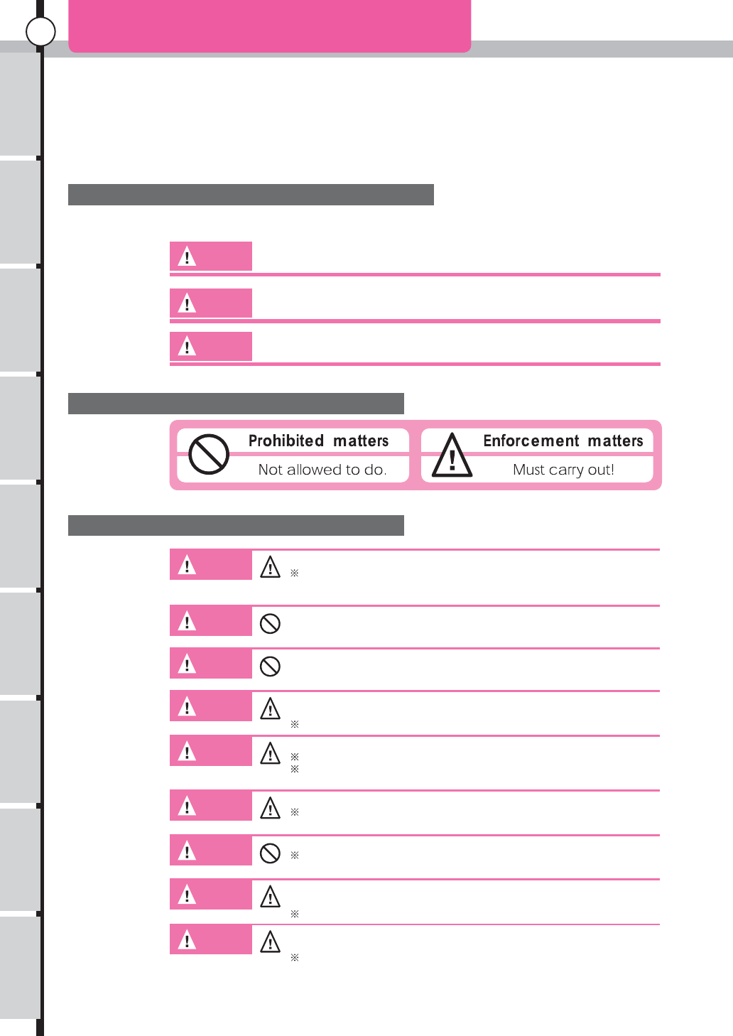
Explanation of warnings and signs
In this manual, following warnings and signs should be noted carefully.
Danger!
Warning!
Caution!
Failure to observe the matter discussed in such an item poses a serious
threat of death or severe injury.
Failure to observe the matter discussed in such an item poses a possibility
of death or severe injury, and a great likelihood of damage to the equipment
or property.
Failure to observe the matter discussed in such an item poses a possibility
of injury or damage to the equipment or property.
Meaning of picture indications
Meaning of picture indications
Warning!
Be certain to use only KO Propo genuine crystal sets (transmitter and receiver).
Other crystals may vary in frequency, which could lead to misoperation or loss of
control.
Warning!
Prevent metal parts in the model ( Car, or Boat ) from touching caused by
vibration.
Warning!
This product is only designed for surface radio control models. Do not use for any
other purpose.
Warning!
Warning!
If a nicad battery pack is used in the transmitter, be sure to charge
properly before use.
If batteries are not fully charged, the model may run out of control.
Be sure to connect all equipments correctly.
If connections are loose, the model may run out of control.
The vibration may damage the servo and the model may run out of control
Warning!
Warning!
Warning!
Warning!
Be sure to install a receiver with thicker double sided tapes.
A strong shock or vibration may result in the model running out of control.
Do not cut or bundle the aerial wire with other cords.
It may result in decreasing the sensitivity of a receiver and may result in the
model running out of control.
When operating each servo, check that there is no unnecessary force on the push
rod.
It may damage the servo or increase the consumption of batteries.
Be sure to use grommets and to prevent the servo from touching any metal or
carbon plates directly.
The vibration may damage the servo and the model may run out of control.
Meanings of
warning
and signs
Warning
D
RAF
T
Usage of the
transmitter Features Main Menu
Function Menu
Connecting
the receiver Notes on
installing Description Index
7
FOR THE SAFE USAGE OF THIS UNIT-2
Notes Before Installation
Caution!
Caution!
Warning!
Warning!
Warning!
Warning!
Warning!
Warning!
Warning!
Warning!
Warning!
Caution!
Caution!
Caution!
Caution!
Notes on Driving (Sailing)
Be careful not to reverse the polarity of the transmitter and the receiver.
Reverse polarity could damage the unit.
Be sure to use genuine KO Propo products e.g. transmitter, receiver, ESC and
other optional parts.
We cannot assume any responsibility for the use of other companies’
products with this unit.
When turning on the power switch, be sure that the frequency band is
available.
The models using the same frequency will run out of control
Do not use this unit in thunderstorms.
There is a possibility of lightning striking the antenna.
Do not use the transmitter in the rain or in a location where water might get on
it.The unit may become wet, which causes loss of control.
Do not run the model in the following places.
Near to other radio control car circuits. (within 3km)
Near to people or on the road.
The surface of the water where there are actual sized boats.
Near to electric wires and communication facilities.
In the case of the model running out of control, it will be very dengerous.
Do not run the model when you experience difficulties in concentration through
tiredness, alcohol or medication.
The mis-judgement may result in accidents.
Be sure to extend the aerial of the transmitter to full length.
The emission of incorrect signals will cause the model to run out of control.
Do not allow any plastic parts to come in contact with fuel and exhaution.
Doing so causes risk of damage.
Be sure to confirm that the model memory is matched to the models currently
running.
Not doing so may cause the model to run out of control.
When you make fanctional changes, be sure to stop the engine or disconnect
the motor lead wire.
Always turn on the switch on the transmitter first, followed by the receiver.
When turning off the switch, always turn off the receiver first, followed by the
transmitter.
If you don’t follow the correct order, the receiver may get interference and
Attach a band plate when you operate the unit.
Display your frequency clearly to other people.
Do not touch the engine, motor, ESC where heat is generated.
May result in burning.
Because the transmitter emits high-frequency energy, do not touch the antenna
while the transmitter is in use.
Warning
Coution
Coution
DRAF
T
Usage of the
transmitter Features Main Menu
Function Menu
Connecting
the receiver Notes on
installing Description Index
8
FOR THE SAFE USAGE OF THIS UNIT-3
Notes on Driving (sailing)
Warning!
Warning!
Caution!
Caution!
Danger!
Danger!
Danger!
Danger!
Danger!
Danger!
Notes on Charging Nicad Battery and Hydropack (sold separately)
In the case of an electric-powered car, be sure to disconnect the nicad
battery afterwards.
It may cause fire or the model to run out of control in case of the
switch being left on.
When storing the transmitter, batteries, and models, be sure to keep
them out of the reach of children.
It may result in damage by chemicals.
Be sure to disconnect the battery from the transmitter when not in use
for a long time.
It may damage the transmitter if you leave the battery in the
transmitter for a long time.
Do not store the transmitter in the following places.
Extremely hot or cold places (+40 , -10 ,).
Direct sunshine.
Places with high humidity.
Dusty places.
If you store the unit under these circumstances, it may result in
misoperation or damage to the unit.
Do not short the battery terminals.
It is dangerous because it may cause the outbreak of fire or explosion.
Never incinerate the batteries.
It is very dangerous because they may explode.
Be sure to use KO Propo charger and to use correct charging current. (1A)
Avoid over charging the battery. Over charging does not only damage the
battery, but can cause excess heat build-up and possibly fire, which results
in serious accidents.
There is a possibility that the auto cut-off function will fail to operate by
other company’s chargers.
In the case of liquid leaking from battery, Avoid eye/skin contact with the
liquid. Burns and blindness may occur. Apply large amounts of water and
contact a doctor immediately for treatment.
Do not apply a big shock to the batteries.
It may damage the battery and result in short circuits and possibly a
fire.
Do not dismantle or modify the battery.
Dismantling the battery may cause liquid to leak out and it is very
dangerous
Do not wet batteries and do not charge wet batteries.
It may cause excess heat build-up and damage..
Nicad batteries are recyclable.
Please support recycling.
Warning
Coution
Danger
D
RAF
T
Features Main Menu
Function Menu
Connecting
the receiver Notes on
installing Description Index
9
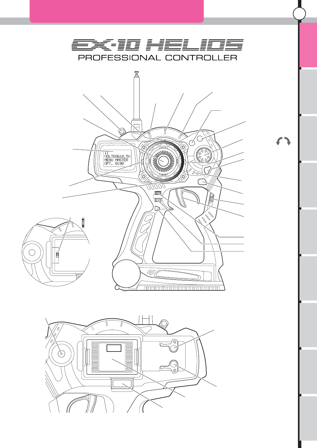
NAMES OF PARTS OF THE TRANSMITTER
Hook ET1 Lever
Antenna
Steering Wheel
12x4 LCD Display
ET2 Lever
BT2
Phone Terminal
D.S.C(Direct Servo Controll Terminal)
Multi Access Port
Charging
RF Module
Throttle trigger
Power Switch
Back key
Power indicator
Enter Key
Et3 Lever
Jog Dial
(+)Plus key
(-) Minus key
(+)
(-)
Throttle acceleration indicator
Throttle A.B.S.
indicator
Throttle speed
indicator
ET4 Lever
ET5 Lever
BT1
Mode Change Switch
High Speed
Normal
Factory default setting
ET1: Steering trim
ET2: Throttle trim
ET3: Throttle brake
ET4: Steering travel
ET5: Not Assigned
BT1: Not Assigned
BT2: Not Assigned
There is a switch in the back when
the RF module is removed.
Please refer P15 for the details
Usage of the
transmitter
DRAF
T
Features Main Menu
Function Menu
Connecting
the receiver Notes on
installing Description Index
10
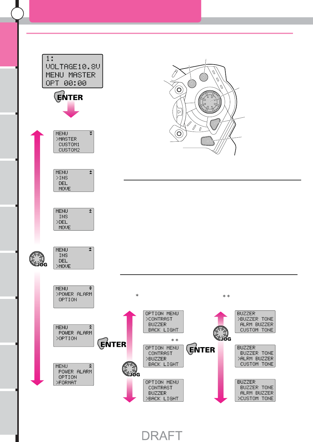
These screens are displayed when the main menu is opened.
Change menu
Add menu
Delete menu
Move menu
Power alarm
Option menu*
LCD Contrast
Buzzer Set
Buzzer Tone
Alarm Buzzer Set
Custom Tone Editor
Back Light
Format (note)
Initial screen
The menu is displayed when ’Enter’ is pressed from the initial screen.
The following 11 kinds of settings can be done in the main menu.
Change Menu
Add Menu
Delete Menu
Move Menu
Power Alarm
Option Menu: LCD Contrast
Option Menu: Buzzer Set: Buzzer Tone
Option Menu: Buzzer Set: Alarm Buzzer
Option Menu: Buzzer Set: Custom Tone
Option Menu: Back Light Setting
Format (note)
Option Menu: Option Menu: Buzzer Set:
(note) This format is displayed only when the Data Pack is installed.
Use Jog Dial or (+) (-) keys to change each screen.
Press ’Enter’ key to open each setting screen.
Option Menu divides into three items when it is opened.
In addition, an item is divided into the buzzer settings.
P17
P26
P26
P27
P27
P28
P28
P29
P29 P29
P29
P29
P30 P31
Plus Key
Minus Key
Jog Dial
Enter Key
Back Key
Please see each reference page about a detailed operation method after each screen is opened.
SCREEN TABLE MAIN MENU
Usage of the
transmitter
Features Main Menu
Function Menu
Connecting
the receiver Notes on
installing Description Index
11
SCREEN TABLE FUNCTION MENU
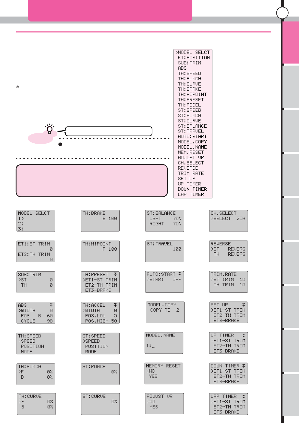
These screens are displayed when the function menu is opened.
Model Select
ET Position
Sub Trim
A.B.S
Throttle Speed
Throttle Punch
Throttle Curve
Throttle Brake
Throttle High Point
Throttle Pre Set
Throttle Acceleration
Steering Speed
Steering Punch
Steering Curve
Steering Balance
Steering Travel
Automatic Start
Model Copy
Model Name
Memory Reset
Adjust Volume
Channel Select
Reverse Switch
Trim Rate
Select Up
Up Timer
Down Timer
Lap Timer
It returns to an initial screen if it keeps pushing the
backing key from any screen is displayed.
Model Select
ET Position
Sub Trim
A.B.S
Throttle Speed
Throttle Punch
Throttle Curve
Throttle Brake
Throttle Preset
Throttle High Point
Throttle Acceleration
Steering Speed
Steering Punch
Steering Curve
Steering Balance
Steering Travel
Automatic Start
Model Copy
Model Name
Memory Reset
Adjust Volume
Channel Select
Reverse Switch
Trim Rate
Set Up
Down Timer
Lap Timer
Up Timer
P32
P33
P34
P35/36
P37/38
P39
P40
P41
P42
P43
P44/45
P46/47
P48
P49
P50
P51
P52
P53
P54
P55
P56
P5
7
P5
8
P5
9
P6
0
P61
P6
2
P6
3
Having assumed that the function name is chosen from the display of
the list of the function menu with Jog Dial, and 'Enter' is done opens
and respect opens.
The following screen will be opened when function name is chosen by
Jog Dial or (+), (-) keys then Enter is been pressed.
Can not return to initial screen.
All of 28 function menu will be displayed when Master is been set
for the menu.
In Custom 1 and Custom 2, only the set content is displayed.
To display all, please refer Change Menu (P17 P26) and return
display menu to the Master.
The function menu opens when Jog Dial or (+), (-) keys are operated
from an initial screen.
28 kinds of the right are all function menus.
Please see each reference page about a detailed operation method, after each screen is opened
Usage of the
transmitter
advice
DRAFT
DRAFT
RAFT
R
Features Main Menu
Function Menu
Connecting
the receiver Notes on
installing Description Index
12
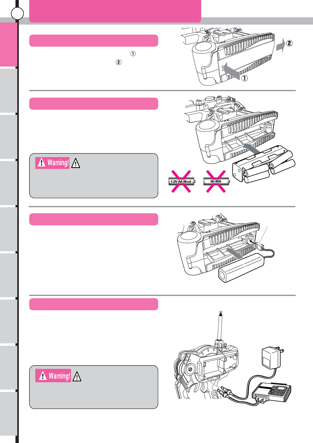
(1)It moves it in the direction of the arrow of .
while pushing the part of the arrow of .
How To Insert Batteries 1
How to open the cover.
How to insert batteries. (option)
How to insert battery pack (option)
About Charging (only for battery packs)
Do not use AA size Ni-cd or NiMH batteries.
The inside of the transmitter corrodes by
generating the gas when charging it.
Do not charge when dry cell batteries are used.
The transmitter is damaged due to the liquid
leakage and the explosion when charging it.
Facing correct
direction
Usage of the
transmitter
Please attach included sponge to the battery lid
when the battery pack is used.
Connect AC Mains charger or DC 12V charger (KO Propo
products) as shown in figure.
The charging time from flat condition is 14-16 hrs for AC
Mains charger.
(1)The connector is inserted noting the direction as shown in figure.
(2)Insert battery pack and close the cover.
(3)Be careful not to trap the cord.
(1)The direction is matched to the display of the plus or minus of the
dry battery box, and eight AA size batteries are put.
(2)The direction of the terminal of the dry battery box and the terminal
of the transmitter is matched and it pushes it into the interior.
(3)The battery cover is closed
D
RAF
T
Features Main Menu
Function Menu
Connecting
the receiver Notes on
installing Description Index
13
Please note the battery pack can not be discharged using charging jack.
Please remove battery pack from main unit for discharging.
How to Insert Batteries 2
About Discharging Battery Pack
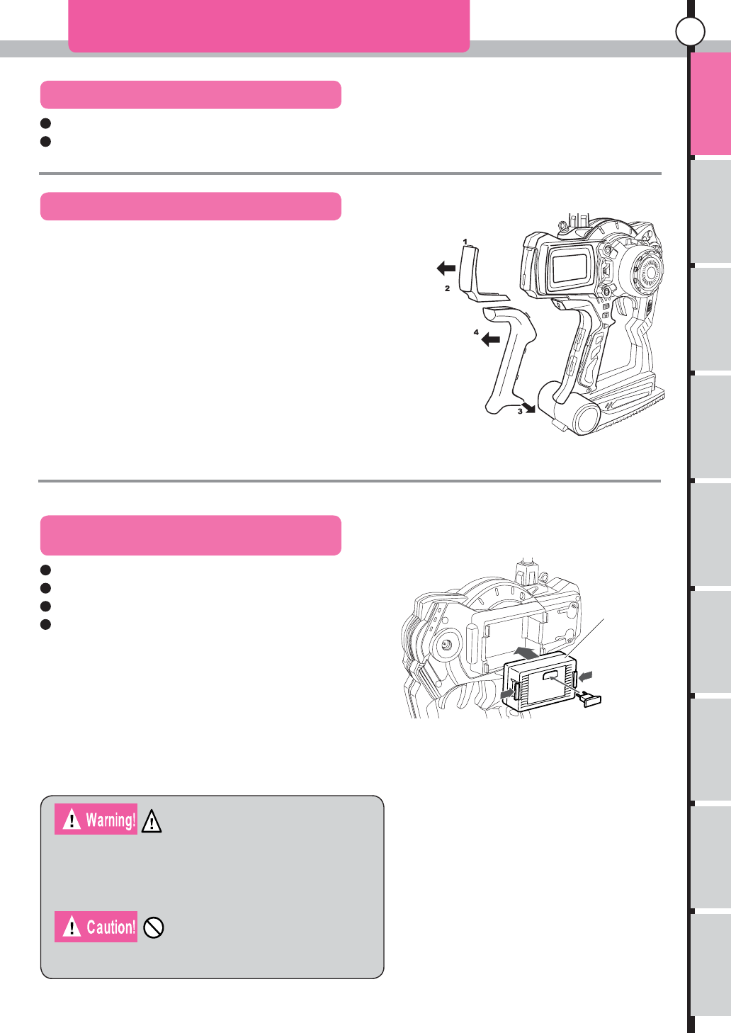
Color Pad and Replace Grip
Changing the RF Module and Crystals
When changing the crystals, be sure to use genuine
FM-type transceiver crystals from KO Propo. Crystals
from other manufacturers may operate at slightly different
frequencies, resulting in loss of control.
Only the RF Module for EX-10 Helios can be used.
Pad
Grip
RF Mod
u
Crystal
Usage of the
transmitter
Change the RF Module for changing the frequency range.
Change the crystals for changing the frequency. (band)
Be sure to turn off the switch when you change the RF Module or crystals.
Insert the crystal properly.
It does in the reverse order of the removing procedure. The lower side
is done in the slide after the fingernail of (1) is previously encased of
the pad, and it pushes it.
The grip does the whole in the slide and pushes the fingernail on the
side in six places in pushing total into the case. If it is not easy to enter,
it pushes it by a minus driver etc. noting that the case is not damaged.
Finally, push the guide pin that exists in the part of the arrow of (3) into the case.
How to attach pad or grip.
After it pulls it in the direction of an arrow lower (2), the pad removes
fingernail (1)
After expanding lower side (3) outside, the grip pulls the whole in
direction (4) of the arrow.
How to remove pad or grip.
DRAF
T

Features Main Menu
Function Menu
Connecting
the receiver Notes on
installing Description Index
14
Insert dry cells or battery pack into the transmitter (P12)
Be sure to charge battery pack before use.
How to Use Transmitter-1
Preparation
Switching the Power On
advice
Other than MASTWER, it can be changed to CUSTOM 1 or CUSTOM 2
which you can change display items by yourself.
Change the menu list of initial screen that it is displayed when Jog Dial or (+), (-) keys are
operated.
Change the setting of POWER ALARM of the main menu. At shipment from
factory the alarm will sounds when the unit does not operate for more than 3
minutes.
The buzzer sounds if it doesn't operate it for a long time. I want to change this setting.
Open the function menu and perform SET UP.
Change function assignment of ET lever or BT button.
Use Mode Switch (detach RF module from main body) and CH.SELECT of
function menu (P57).
Change operation mode of response.
Change settings of operations.
Open the main menu and then open the BUZZER from OPTION to set up.
Want to change pitch of the buzzer beep or change the melody.
(The backlight is [Auto] at factory default.)
Open the main menu and then open the BACK LIGHT from OPTION to set up.
Changing the setting of the backlight of the LCD.
Open the main menu and then open the CONTRAST from OPTION to adjust.
In case of LCD contrast is too blight or too dark.
P28
P31
P29
P30
Usage of the
transmitter
Changing the display or settings.
A blue power indicator at the right of the main body lights when the power of the transmitter is on and the LCD
display is displayed with the start sound.
The battery will last long if crystal is pulled out or the RF module is detached when only the transmitter is operated.
Moreover, when only the transmitter is operated when the management of the band is done in the course etc. , it is
similar. (Please refer P20 D.S.C page)
Reference page
Reference page
P29
Reference page
P19
Reference page
P60
Reference page
P28
Reference page
P17
Reference page

Features Main Menu
Function Menu
Connecting
the receiver Notes on
installing Description Index
15
Operation concerning memory.
How to Use Transmitter-2
Usage of the
transmitter
If you use the interface adaptor and the PC interface for MAP Multi Access
Port (optional) Most settings of the main unit of the transmitter can be done
with PC, and the setting of the transmitter side be preserved in PC. P21
Want to list many functions for set up.
Want to record more than 25 setting up data.
Want to edit custom tone by the PC.
P20
DSC function can be used connecting DSC cable (option) to the DSC
port.(D.S.C=Direct Servo Controller)
It comes to be able to operate it by the power supply's entering by inserting DSC
Jack in the DSC port.
I want to set it up without emitting signals from the transmitter.
Use the optional feature.
P22
The format appears to the menu only when the data packing is installed.
Please execute the format in the main menu when you use the Data Pack.
P53
Select MODEL.COPY from function menu and press enter.
Transferring model memory setting to other model memory.
P55
Select MEM.RESET from function menu and press enter. (Current model memory will be initialized.)
Reset a specific model memory to factory default setting.
Reference page
Reference page
Reference page
Reference page
Reference page
DRAF
T

Usage of the
transmitter Main Menu
Function Menu
Connecting
the receiver Notes on
installing Description Index
16
ABOUT THE OPERATION OF THE LCD SCREEN
Power-supply voltage
Operation timer
(adjusting time display)
Present model memory
number and model name.
Menu list that has been
selected.
Plus Key
Minus Key
Jog Dial
Enter Key
Back Key
n this machine, assume most settings to be an operation system thirdly, that is, Jogdial and the
"Enter", "Back" key possible to enable an intuitive operation.
Moreover, the change menu system that can efficiently use it with more set screen is newly adopted.
Enter key: The main menu opens when "Enter" is pushed.
Back key: Nothing happens.
+.- keys: The function menu will open.
Jogdaial: The function menu will open.
Press +.- keys together: Reset Operation timer
It is a menu that opens when "Enter" is pushed from an initial screen.
Mainly, the setting related to the system can be set. The content set by
this menu is not independent in each model memory.
This is a menu that opens when Jog Dial or +.- keys is operated from Initial
Screen.The position that opened last time is memorized while the power
supply has been turned on.
Set an independent content for each model memory. Although there are
lots of functions, the displayed function is customizable by the menu list
switch (Page 17). (Change Menu System)
Name of key Names on Initial Screen
From an initial screen
Enter key: It is a key that mainly to select and to decide.
Back key: Mainly, use it when it cancel or it returns to the previous screen.
+.- keys: Use it to increase or decrease a movement and the set value(figure)
Jog Dial: Can be used like +.- keys but a quick operation can be done
Press +.- keys together: Reset a value of settings. (however it is not for all functions)
A key function, besides an initial display
Main menu
Function menu
Page mark
There is a content of the
display below.
There is a content of the
display above and below.
There is a content of the
display above.
About Page mark
Each keys can be operated by pressing. Jog Dial can
be operated by rotating left or right.
Features
It is likely to be displayed not only in main menu but in function menu.
D
RAF
T
Usage of the
transmitter Main Menu
Function Menu
Connecting
the receiver Notes on
installing Description Index
17
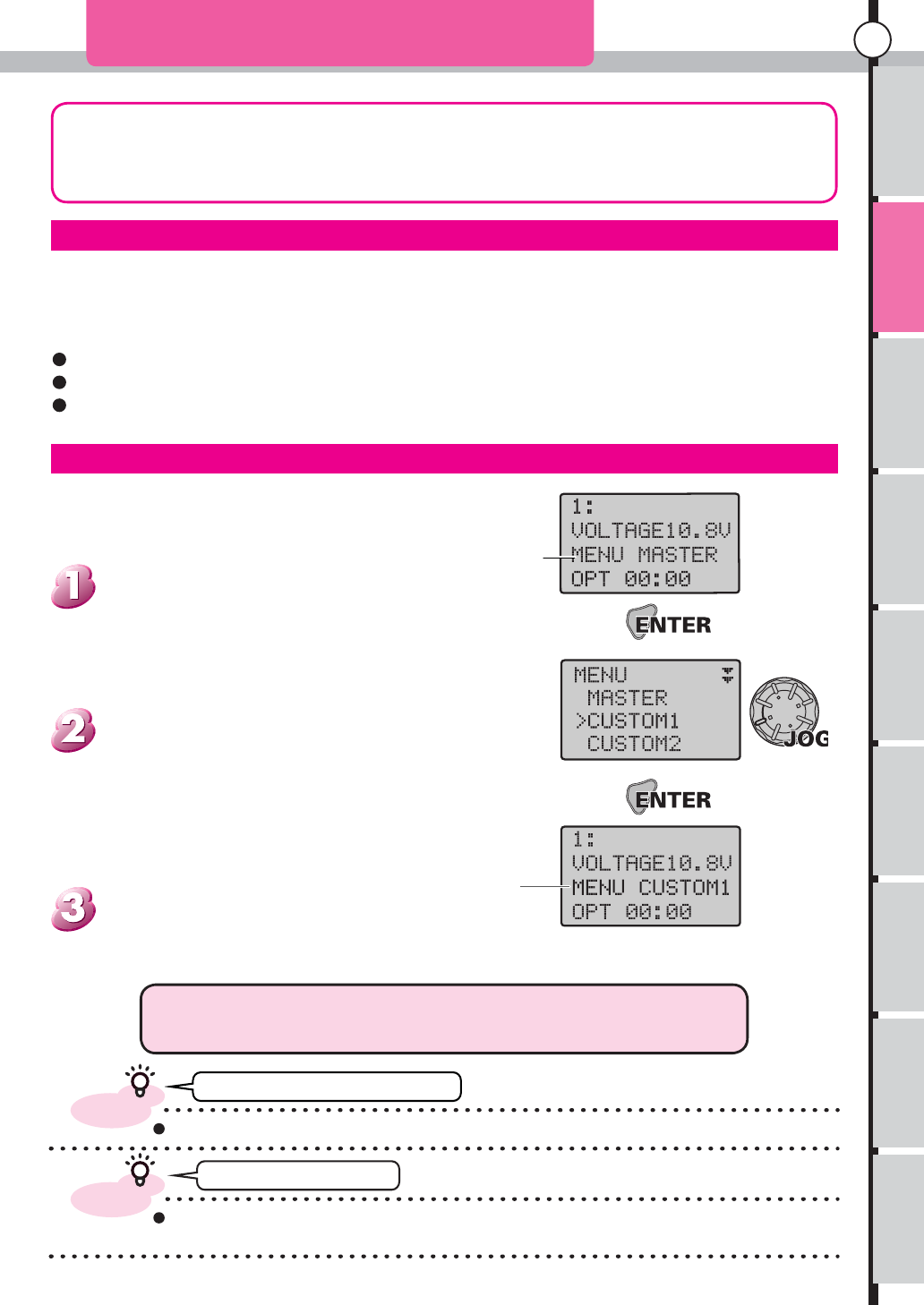
Change Manu
In this unit, to use a lot of functions, Change Menu System is developed, and installed
newly. This is the one that it is made to be able to do by quickly calling practicing more
operation by switching Menu List that registers only the function to often use.
MASTER is using
Changed to
CUSTOME1
In the example of the display,
it switches from MASTER to
CUSTOM1
.
It is an explanation of the procedure for switching actually.
Select the menu that you want to display in the main menu.
About Change Menu
Change Menu Procedure
By registering the content squeezed to CUSTOM1 or CUSTOM2 from a lot of function menu items, the switch is
..function item.. quick and it is made to be able to do.
For instance, CUSTOM1 is a lot of items used for the practice CUSTOM2 registers the item for the race.
The switch of the item used can be easily made by three actions. (Enter, Jog, Enter)
If Master is used, all items are displayed.
Unregistered items functions are also effective. (Just not displayed)
Can not return to initial screen.
Can not select CUTOM2!
Please see main menu P26 about detailed operation methods such as the item
additions and editing each menu.
The screen returns to an initial screen, the
name of function menu is been changed to the name
that selected.
Following three menu items MASTER, CUSTOM1 and
CUSTOME2 will be displayed at the first screen of
main menu. Select the items you want to use by Jog
Dial or +.- keys then press enter.
Press the enter key from the initial screen
to display main menu.
Features
advice
Whatever the display screen is, it returns to an initial screen if you keep pressing back key.
advice
CUSTM2 can not be selected at factory default settings because there is no items are registered. I can be used if you
register or add items in the menu contents. (Add menu P26)
DRAF
T
Usage of the
transmitter Main Menu
Function Menu
Connecting
the receiver Notes on
installing Description Index
18
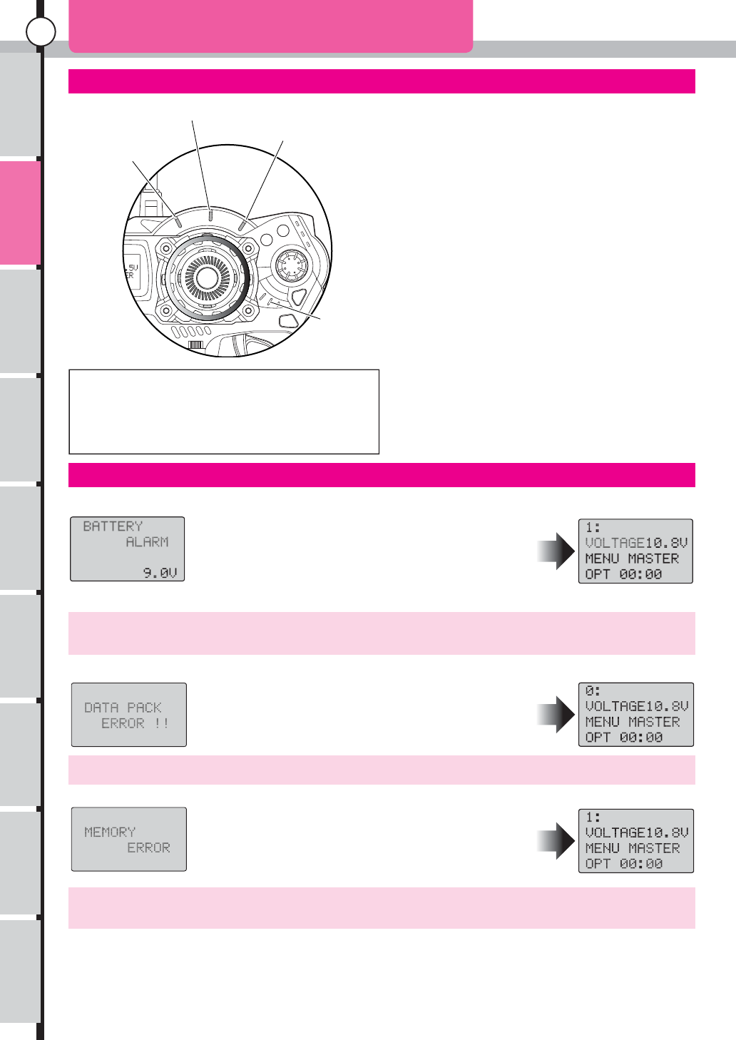
Battery Alarm This is displayed when the power supply voltage drops about 9V or less.
The character of the BATTERY ALARM flashes. The
power indicator flashes. The alarm buzzer sounds. And
the backlight is compulsorily turned off. VOLTAGE of LCD
keeps flashes though it returns to an initial screen for any
key operation.
Indicator warning
Throttle Speed Indicator
When Throttle Speed (P37) is effective, it
flashes. Moreover, the function of On/Off of
Throttle Speed is allocated in ET and the button,
it flashes too.
Throttle A.B.S. Indicator
When Throttle A.B.S (P35 36) is effective, it
flashes. Moreover, the function of On/Off of the
Throttle A.B.S. is allocated in ET and the button,
it flashes too.
Throttle Acceleration
When Throttle Acceleration (P44) is effective, it
flashes. Moreover, the function of On/Off of the
Throttle Acceleration is allocated in ET and the
button, it flashes too.
Power Indicator
When the power is turned on, it lights.And
It flashes when the voltage drops below 9V.
(battery alarm)
Throttle A.B.S Indicator Throttle Acceleration
Indicator
Throttle Speed
Indicator
Power Indicator
Because three indicators other than the power indicator
flashes regardless of a set value when it is turned on
with ET and the button, it is not limited that the function
works.
After it returns to an initial screen, Flashing VOLTAGE and Flashing power indicator are released if the
voltage is more than the warning voltage for one minute.
Data Pack Error It is displayed when there is something wrong with the Data Pack while using it.
DATA PACK ERROR!! flashes.
After any key is operated, Model 0 is displayed.
Memory Error When malfunction happens to the access of the memory, it is displayed.
MEMORY ERROR!! flashes.
After any key is operated, model memory (model memory 1)
will operate at initial condition.
If the power is turned on again and it is normal, it operates by
an original setting.
If this message does appear frequently, send the transmitter to our service department for repairs.
Please see model selection (P32) about the display of model memory 0.
Power Alarm The alarm sounds when time that nothing is operated exceeds set time.
It will set it in three minutes at factory setting.
The time can be set at Main Menu: Power Alarm (P28)
The sound of alarm can be set at Main Menu: Option: Buzzer (P29)
About the display of each indicator.
Warning Display
Features
D
RAF
T
Usage of the
transmitter Main Menu
Function Menu
Connecting
the receiver Notes on
installing Description Index
19
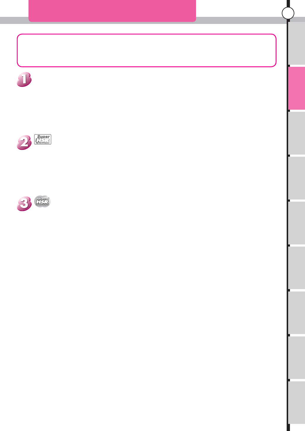
Movement mode (Responce mode)
This Unit can select from 3 mode. to change the mode adjust the switch below of the RF module. and
adjust the channel select in function mode.
Features
DRAF
T
Usage of the
transmitter Main Menu
Function Menu
Connecting
the receiver Notes on
installing Description Index
20
Features
D
RAF
T

Usage of the
transmitter Main Menu
Function Menu
Connecting
the receiver Notes on
installing Description Index
21
Features
DRAF
T

Usage of the
transmitter Main Menu
Function Menu
Connecting
the receiver Notes on
installing Description Index
22
Features
D
RAF
T

Usage of the
transmitter Main Menu
Function Menu
Connecting
the receiver Notes on
installing Description Index
23
Features
DRAF
T

Usage of the
transmitter Main Menu
Function Menu
Connecting
the receiver Notes on
installing Description Index
24
Features
D
RAF
T
Usage of the
transmitter Features Main Menu
Function Menu
Connecting
the receiver Notes on
installing Description Index
25
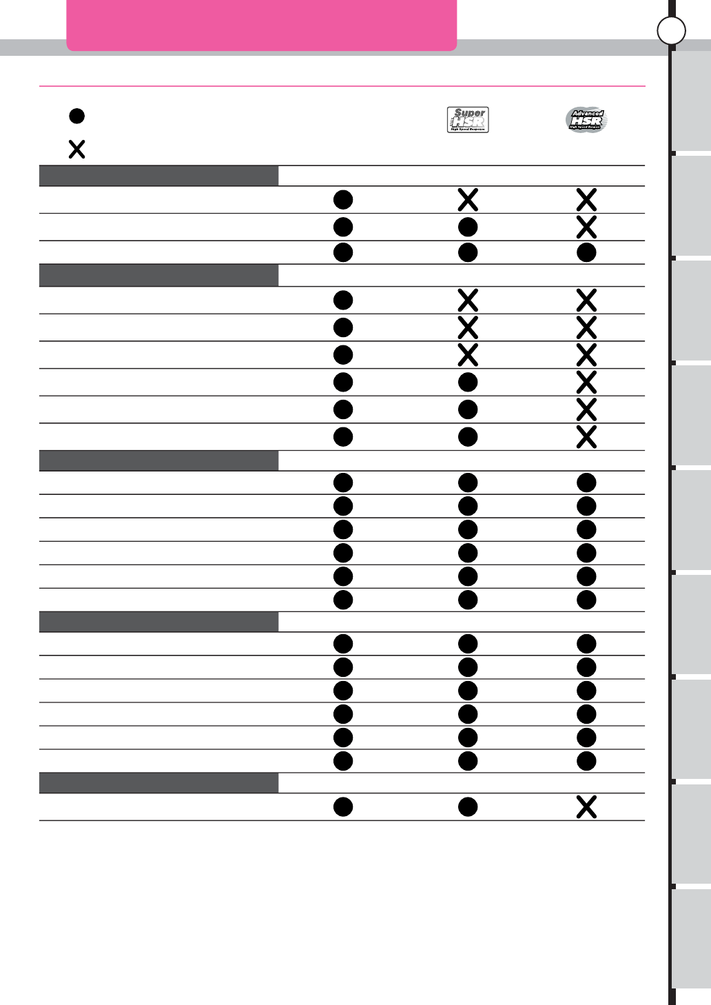
Response Mode Compatibility Table
Incompatible
Compatible
Normal Super High Speed Advanced High
Speed
Receiver KR-297FZ(Discontinued)
KR-301F
KR-302F
Analog Servo PS-401
PS-712FET
PS-713FET
PS-2173FET
PS-2174FET
PS-2113FET
Digital Servo PDS-947FET
PDS-2123FET
PDS-2143FET
PDS-2144FET
PDS-2343FET
PDS-2344FET
ESC EZ-1000
KSC-1000FR
KSC-1100FR
KSC-1200F
VFS-2000
VFS-2000J
OthersFail Safe Adapter(FSA-1)
Response Mode Compatibility Table
DRAF
T
Back Key
Enter Key
JogDial
+/- Key
Reset
Features Function Menu Connecting
the receiver
Usage of the
transmitter Notes on
installing Description Index
Main Menu
26
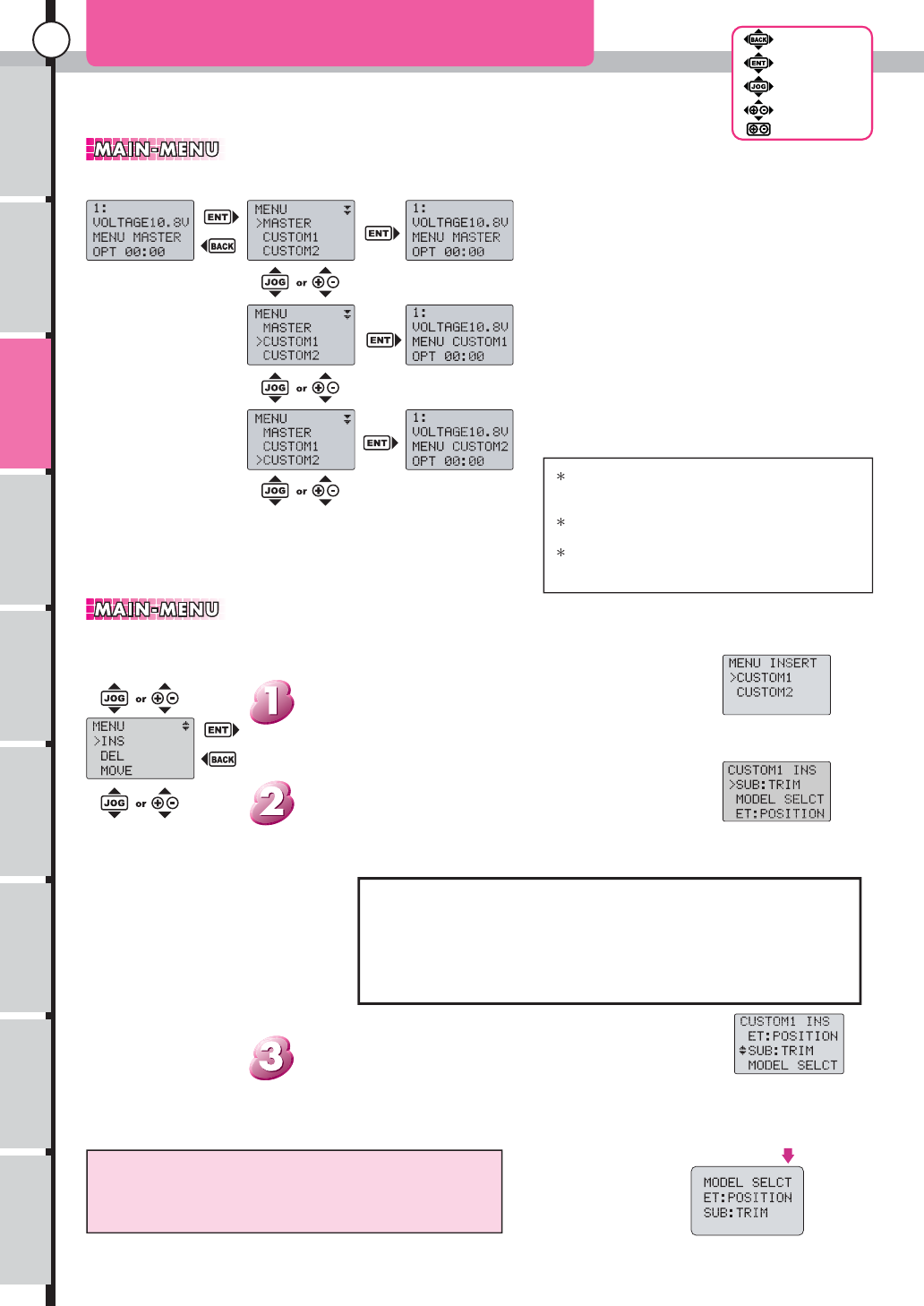
Menu addition
It is the menu displayed when "Enter" is pushed from the initial screen.
Main menu (1)
to Menu addition
The menu name does the blinking display if not
registered in each menu at all and it is not possible to
select it.
In the state of the first stage, as for CUSTOM1, only
MODEL.SELECT is registered.
In the state of the first stage, CUSTOM2 is empty.(It
is not possible to select it.)
Selected CUSTOM1
Selected SUB:TRIM
SUB:TRIM has
been selected on
this screen. It
tries to insert
SUB:TRIM after
ET:POSITION on
this screen.
It becomes the order.
(Displayed on the right)
It is possible to add it continuously by repeat. Push the
"Back" key when stopping it.(Or, jump to an initial screen
at dash when the "Back" key and "Enter" are pushed at
the same time.)
Additional position
Decide the position where the function selection with Jogdial or
the +, - key is inserted and push "Enter". Insertion is fixed, and
the screen returns to the selection of the function name of two.
The added function name is a list of the
right. however, the one registered in the
menu list is not displayed
Function name selectin
The function name that wants to be added and push
"Enter"..
Menu name selection
Select the added menu name. Move the cursor to either of
CUSTOM1, CUSTOM2 with Jogdial or the the +,- key and
push "Enter".
Add the item to the menu list.
It is possible to add it to CUSTOM1 and CUSTOM2.(It is not
possible to add it to MASTER.)
Back Key
Enter Key
JogDial
+/- Key
Reset
Main Menu
The first screen of the main menu becomes a
selection of the change menu system.
Displayed MASTER, CUSTOM1, and CUSTOM2
are name of the menu screen respectively.
It is selected by pushing "Enter" after it moves to
the menu name you want to select the cursor with
Jogdial or the +.- keys, and the display returns to an
initial menu.
The menu is not changed when returning to an initial
screen by pushing the back key.
Change menu system
MODEL SELCT
ET:POSITION
SUB:TRIM
ABS
TH:SPEED
TH:PUNCH
TH:CURVE
TH:BRAKE
TH:HIPOINT
TH:PRESET
TH:ACCEL
ST:SPEED
ST:PUNCH
ST:CURVE
ST:BALANCE
ST:TRAVEL
AUTO:START
MODEL.COPY
MODEL.NAME
MEM.RESET
ADJUST VR
CH.SELECT
REVERSE
TRIM RATE
SET UP
UP TIMER
DOWN TIMER
LAP TIMER
DRAF
T