Kondo Kagaku T125003 Remote Control Transmitter User Manual manual 52 78
Kondo Kagaku Co., Ltd. Remote Control Transmitter manual 52 78
Contents
- 1. manual 52 78
- 2. manual 1 26
- 3. manual 27 51
manual 52 78
Usage of the
transmitter Features Main Menu Connecting
the receiver Notes on
installing Description Index
52
Back Key
Enter Key
JogDial
+/- Key
Reset
Function Menu
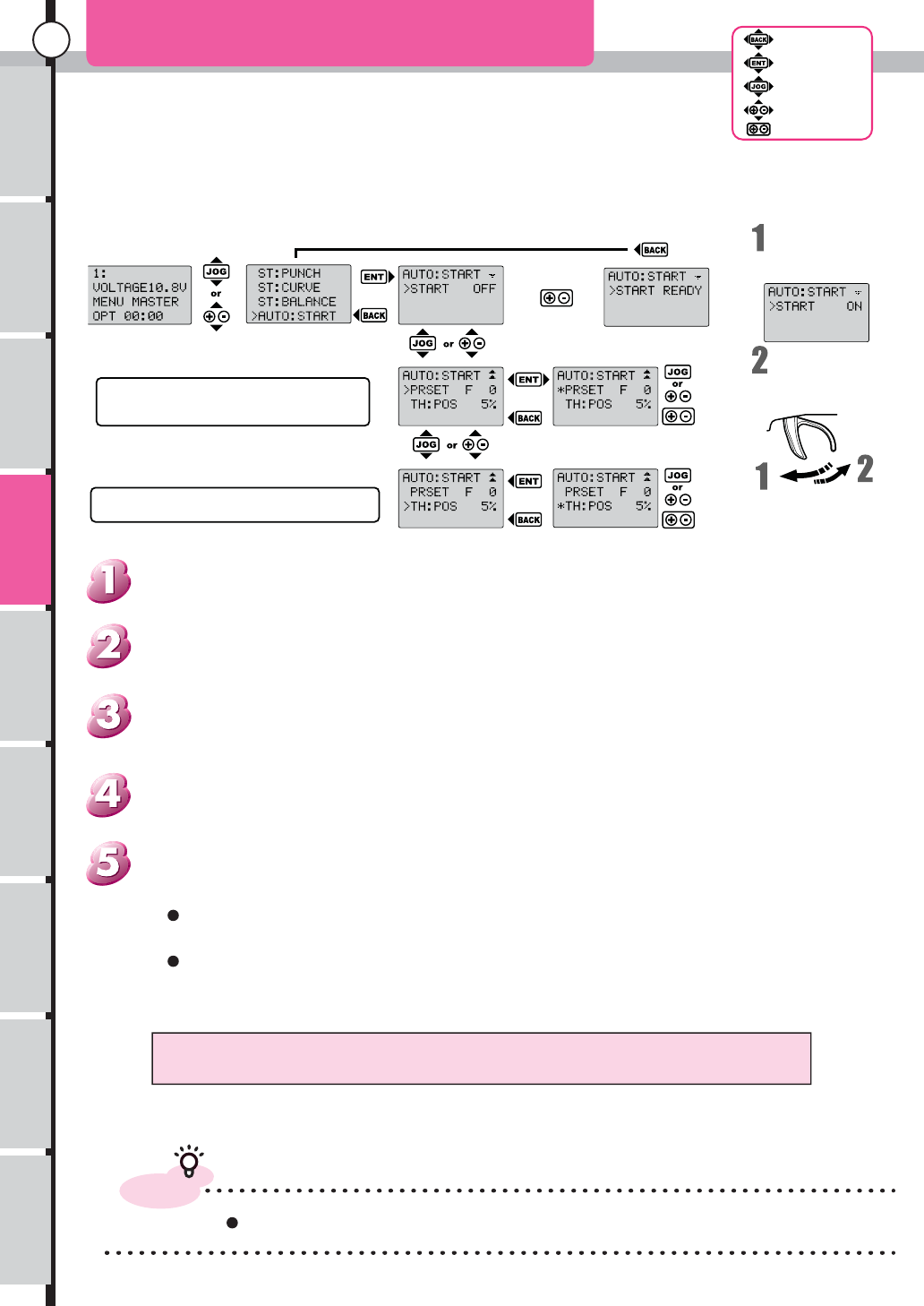
AUTO START
Return at Back key, But ready are still existing.
Reset then start blinking "READY"
Set Throttle position.
Set trigger position to start function
Pull the trigger to
turn on the
TH:POS function
When back the
trigger display
OFF.
When came back during on and off light, it is still effective
advice
Please check the movement before use.
PRESET : Position of throttle when function the AUTO START
Initial Value F 0 Max F150 Min F 0
TH:POS : Position to start AUTO START
Initial Value 5% Max 100% Min 5% or OFF
Push Enter or Back key to return to Menu list.
Push enter key to change the cursor. to editable each item.
Setup value can reset by push reset key.
When reset at first screen. AUTO START function will be waiting mode
Use Jog dial or + ,- keys to move at setup screen
(Can not move to setup screen While blinking the "READY")
Use "Jog dial" key or "+,-" keys. to choose the "AUTO:START" from Menu list.
From initial screen. use "Jog dial" key or "+,-" keys. to open Function menu.
[How to open the set-up screen.]
D
RAF
T
Usage of the
transmitter Features Main Menu Connecting
the receiver Notes on
installing Description Index
53
Back Key
Enter Key
JogDial
+/- Key
Reset
Function Menu
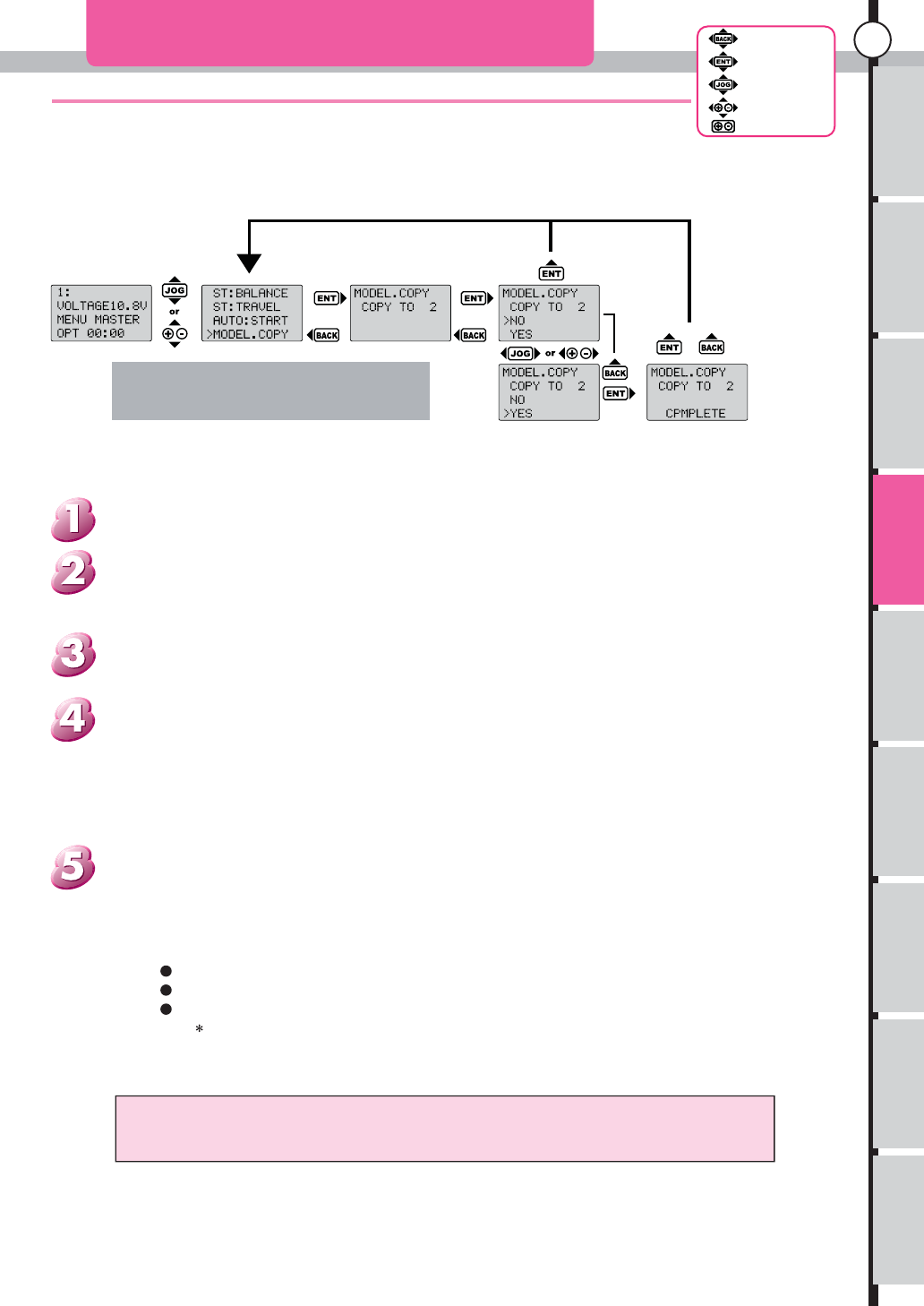
MODEL.COPY
Copy the data in Model memory to other Model memory.
ex. To Copy Data of MODEL
MEMORY1 to MODEL MEMORY2
A copy place is chosen.
"No" is selected
and press enter
key , return to
menu list screen. Press "Enter Key" or
"Back Key,return to
Menu list screen.
"Yes" is selected and
press "Back Key",cursol
Model copy is
finished and blink
"COMPLETE" in
LCD panel.
Overwritten data aren't restored. Please confirm it before
execution well.
It is useful When used in the following situation.
Save the Current data and then try the New setup.
Move the data from Data Pack
Can swap the other data to the memory
Can copy the Data. but the setup data can not copy to the unit
Push "ENTER" key or "BACK" key to Return to Menu list, If Model Copy was done and
"COMPLETE" displayed at screen
Use "Jog dial" key or "+,-" keys. then push "Enter" key
When Select YES then push "ENTER" key: Do MODEL COPY then display "COMPLETE"
When Select NO then push "ENTER" key: Back to Menu list
When Select YES then push "BACK" key: Cursor will mmove to NO
When Select NO then push "BACK" key: Beep sound
Push "Enter" key. to enter setup menu. use "Jog dial" key or "+,-" keys. to Select Model Memory
number.
Use "Jog dial" key or "+,-" keys. to choose the "MODEL.COPY" from Menu list.
From initial screen. use "Jog dial" key or "+,-" keys. to open Function menu.
[How to open the set-up screen.]
Save the current Model memory to other Model memory.
Can select setup that match to the condition of track
It will better to be copied to other memory before changing setting.
DRAF
T
Usage of the
transmitter Features Main Menu Connecting
the receiver Notes on
installing Description Index
54
Back Key
Enter Key
JogDial
+/- Key
Reset
Function Menu
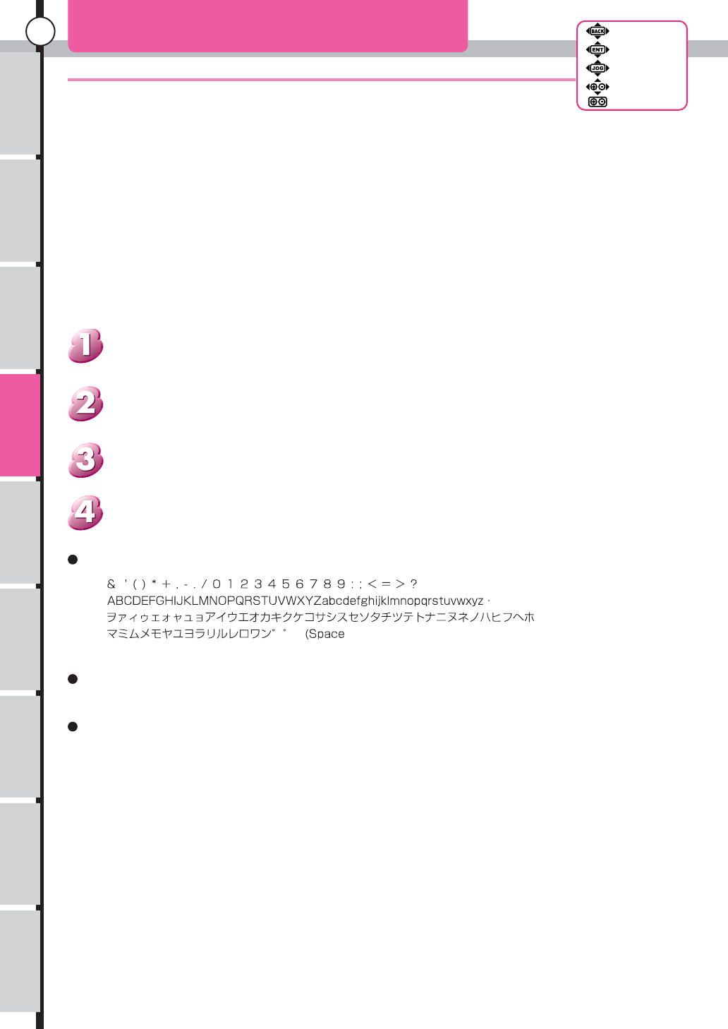
Put name at Model memory
MODEL.NAME(Model Name)
An usable letter:
The letter which can input till 10 characters.
Push enter after select.
Push "Enter" key. to enter setup menu. use "Jog dial" key or "+,-" keys. to adjust the value.
Use "Jog dial" key or "+,-" keys. to choose the "MODEL.NAME" from Menu list.
From initial screen. use "Jog dial" key or "+,-" keys. to open Function menu.
Put the name for Identified model memory
[How to open the set-up screen.]
)
Can use at initial screen and model select that model name.
When enter or edit the name. use Jog dial or +, - key to move the cursor to edit or enter the
characters.
D
RAF
T
Usage of the
transmitter Features Main Menu Connecting
the receiver Notes on
installing Description Index
55
Back Key
Enter Key
JogDial
+/- Key
Reset
Function Menu
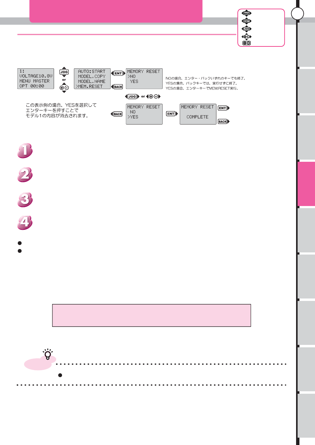
Format to factory setting the model memory.
MEM.RESET(Memory reset)
Erased data aren't restored. Please confirm it before execution well.
advice
Use data pack to save the setup.
Only model memory in use is erased.
Setting of a main menu isn't deleted.
Back to menu list When push back key.
"Yes" is selected and press "Enter Key",delete model memory.
Push "Enter" key. to enter setup menu. use "Jog dial" key or "+,-" keys. to choose Yes/No.
Use "Jog dial" key or "+,-" keys. to choose the "MEM.REST" from Menu list.
From initial screen. use "Jog dial" key or "+,-" keys. to open Function menu.
Model memory will Back to factory setting.
Format all data of model memory.
[How to open the set-up screen.]
DRAF
T
Usage of the
transmitter Features Main Menu Connecting
the receiver Notes on
installing Description Index
56
Back Key
Enter Key
JogDial
+/- Key
Reset
Function Menu
Update information in a system of the VR that consumed.
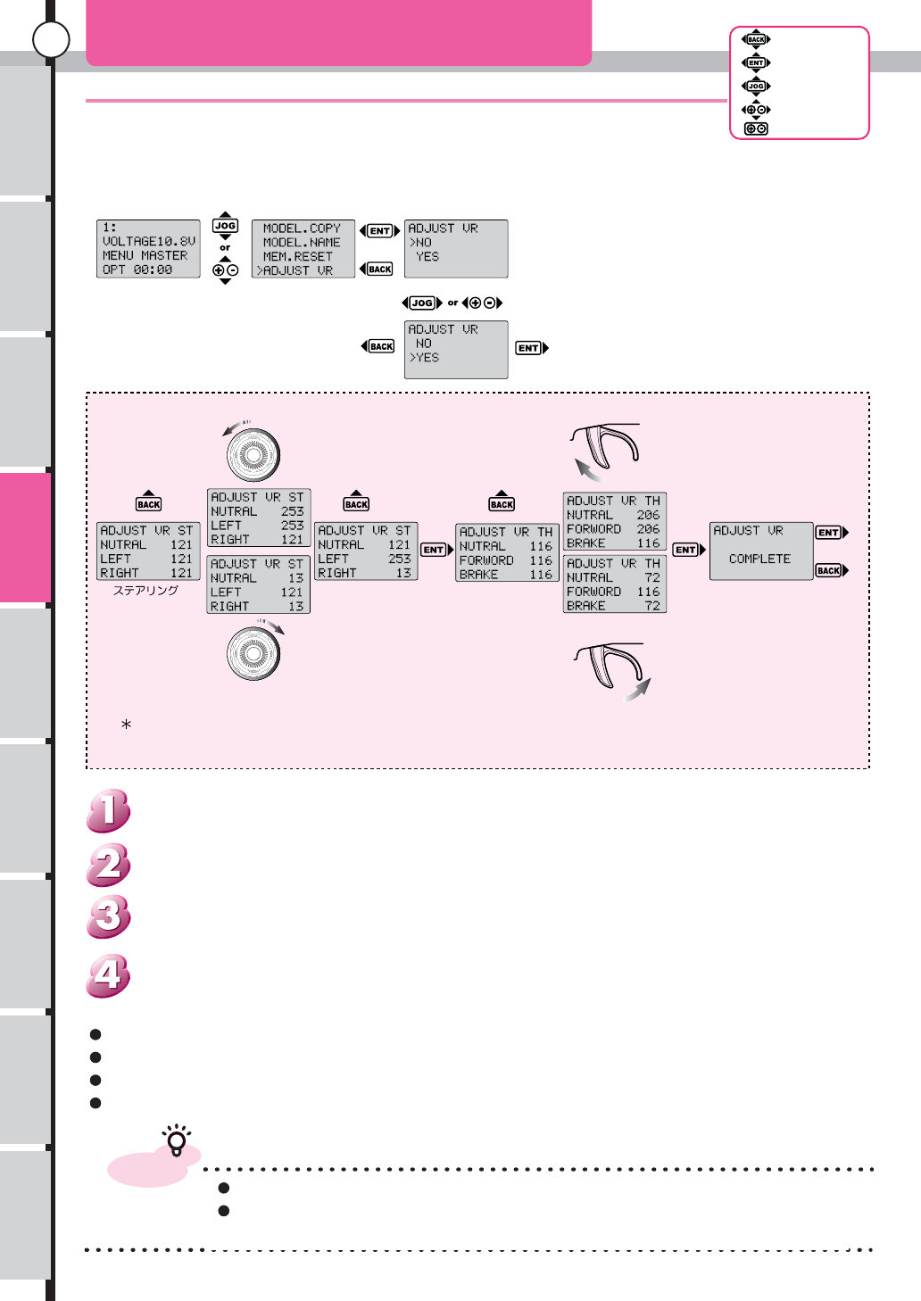
ADJUST VR(Adjust variable resister)
Do ADJUST VRDone
Procedure of Setup ADJUST VR
Control Steering
Control Steering
Full Turn to left
Cancel Cancel Cancel
Full Turn to Right
When display "COMPLETE"
Push "ENTER" key or
"BACK" key to Done.
Control Trigger
Control Trigger
Pull the Trigger to
full foward
Throttle
Push the Trigger
to full back.
This number are sample. This value can not use.
Trigger can be canceled with back key after operation till "Enter" is pushed.(Not Over-write the memory)
Beep sound does it, in the case of a steering or trigger operation data abnormality or no operation and a key isn’t function.
advice
Cause of trouble When use this function imperfectly.
Recommend to send to our service department for repair, when you are not familiar with this
function.
When push "ENTER". not to touch Steering wheel or throttle trigger during execution of "ADJUST VR".
This Function for Cancellation of inconvenience of Consumption of the volume.
It is depend on your Use frequency and An operation method.
When Even this function can not fix the problems, please send to our service department to repair.
Push Back key to return to Menu list.
Select No: Return to Menu list
Select Yes: Do Adjust VR.
From initial screen. use "Jog dial" key or "+,-" keys. to open Function menu.
Use "Jog dial" key or "+,-" keys. to choose the "ADJUST VR" from Menu list.
Move to yes/no to control "Jog dial" key or "+,-" keys.
[How to open setup screen]
D
RAF
T
Usage of the
transmitter Features Main Menu Connecting
the receiver Notes on
installing Description Index
57
Back Key
Enter Key
JogDial
+/- Key
Reset
Function Menu
Normal Response
This mode can use all type of servo and receiver.
Super High Speed Response
This mode is adopted in MARS-R. Old receiver and Servo can't be used at this mode. but the response are improved.
Advanced High Speed Response
This mode can show the original speed. Digital servo is required for this mode.
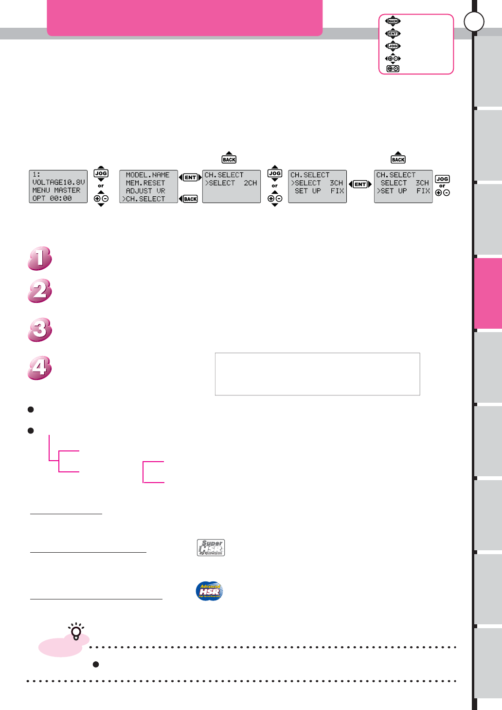
CH.SELECT(Channel Select)
advice
Please see page 19 about details of response mode.
Push Enter to Move between
Item to Item
Push Back to return to menu.
Use Jog dial to control CH3
Select Function
END END
When setting of 3CH are in "FIX":Signal in itself is fired, but can't control
a signal because it was fixed
When assign to BT or ET. can function as switch movement.
or can assign reverse switch to change movement directions
Advanced High Speed Response
Super High Speed Response
High Response
Normal Response
About Response mode: This unit can select from 3 kind of response mode
The movement of channel 3 is adjust max and min of rudder angle (switch-movement)
Push Back key to return to menu list.
To control Jog dial to select 2or 3 channel.
When select 3 channel. the "setup" will display at lower part of screen. then can select the control
function for 3rd channel
At menu list, Move the cursor to the CH.SELECT. use "Jog dial" or "+, -" key. then push Enter.
From initial screen, open the function menu. use "Jog dial" or "+, -" key.
Select 2 Channel or 3 channel.Also select the switch at back of module
When the switch are in High response mode
2channel : Advanced High Speed Response
3channel : Super High Speed Response
[How to open the set-up screen.]
DRAF
T
Usage of the
transmitter Features Main Menu Connecting
the receiver Notes on
installing Description Index
58
Back Key
Enter Key
JogDial
+/- Key
Reset
Function Menu
Set the direction of movement of each channel.
Can Set the direction of movement of each channel.
Use this function when the turing direction of servo is opposite to the wheel/trigger operation.
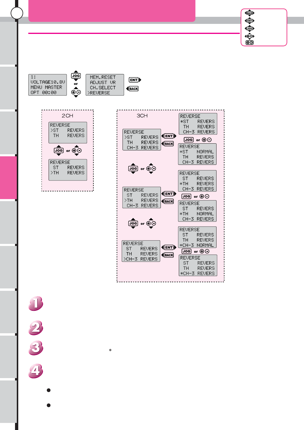
REVERSE (Reverse Switch)
Can change selected Channel
Push Enter or Back key to
return the cursor.
In an Electric car an ESC will adjust Throttle. When reverse isn't set up, it's not
work normally at old ESC.
A movement direction of steering are depend on each cars. Check the setup after
mount to the car.
Push back key to back to menu list.
Push "Enter" key. to enter setup menu. use "Jog dial" key or "+,-" keys. to adjust the value.
The menu for 3ch will display, when selected the CH.SELECT. (page 57)
Use "Jog dial" key or "+,-" keys. to choose the "REVERSE" from Menu list.
From initial screen. use "Jog dial" key or "+,-" keys. to open Function menu.
[How to open the set-up screen.]
D
RAF
T
Usage of the
transmitter Features Main Menu Connecting
the receiver Notes on
installing Description Index
59
Back Key
Enter Key
JogDial
+/- Key
Reset
Function Menu
Adjust Movement volume of the one step of Trim.
Total step of Trim are 100, adjust Movement volume of the one step of Trim.
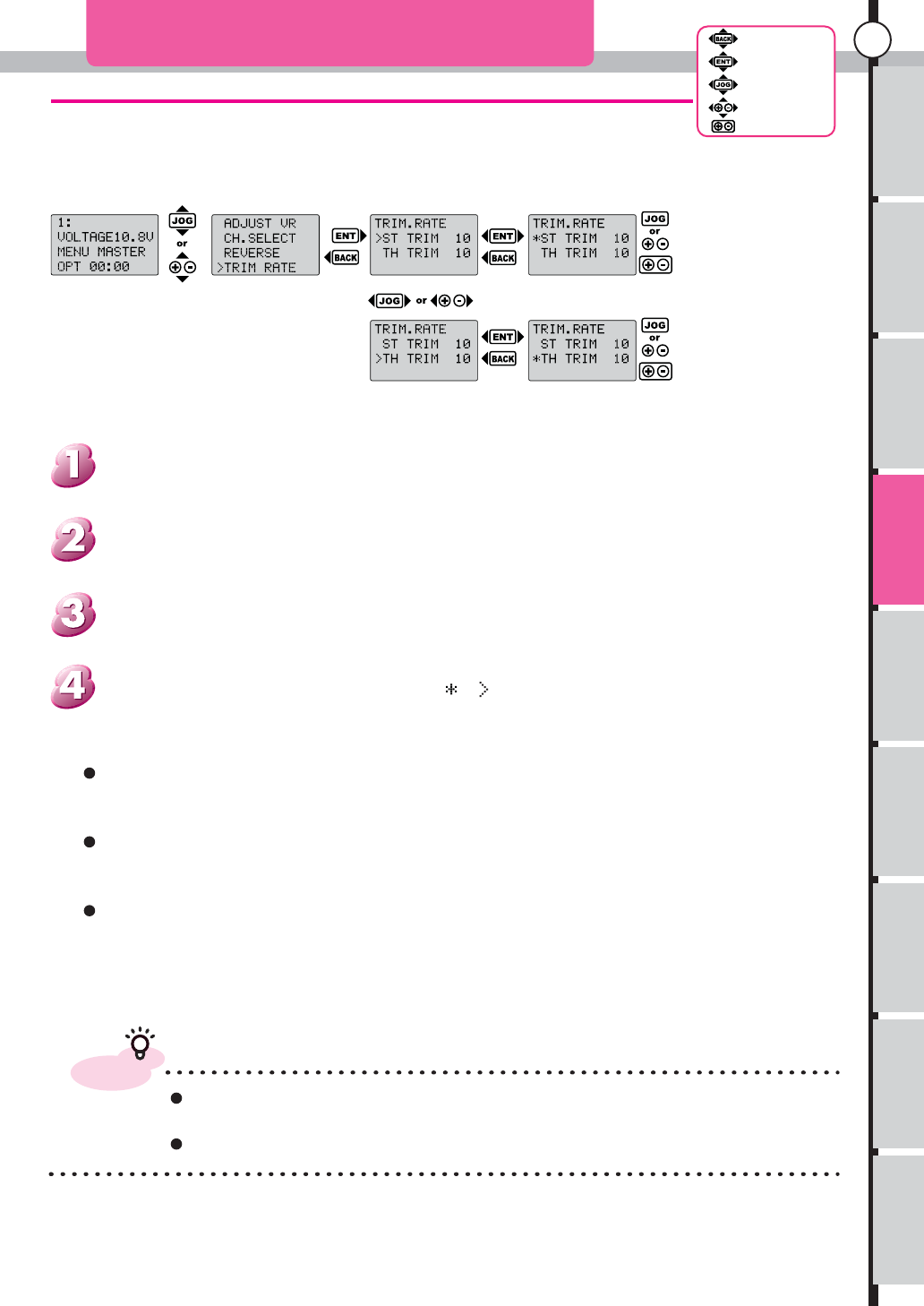
TRIM RATE (Trim Rate)
Initial value
Minimum
Maximum
10
1
20
advice
Can do close adjustment when make a rate to trim small. but some of servo An
enough effect isn't provided
Please do a review of linkage, Before doing particular setting of trim.
1 step of trim Be variable. Movement volume comes to have a small the one
where a number is small
The number of total step doesn't change. When change trim rate, The range
that can adjust will change.
Is cause to out of setting the trim when make a change with the situation
that was already adjusted
Press "EnterKey or "Back Key",change cursol to .And press "Back Key ",retuen to
function menu list screen.
Push "Enter" key. to enter setup menu. use "Jog dial" key or "+,-" keys. to adjust the value.
Use "Jog dial" key or "+,-" keys. to choose the "TRIM.RATE" from Menu list.
From initial screen. use "Jog dial" key or "+,-" keys. to open Function menu.
[How to open the set-up screen.]
DRAF
T
Usage of the
transmitter Features Main Menu Connecting
the receiver Notes on
installing Description Index
60
Back Key
Enter Key
JogDial
+/- Key
Reset
Function Menu
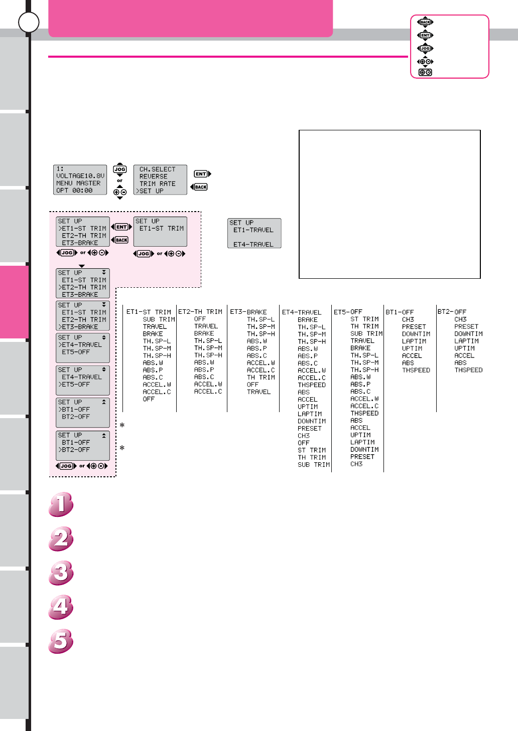
Assign the function to ET, BT
Can assign to ET or to BT Various functions.
Some of function assign at first. but they can change it to customize.
SET UP
Indication contents of each function.
OFF: None
ST TRIM: Steering Trim
SUB TRIM: Steering Sub Trim
TRAVEL: Steering Travel
BRAKE: Trottle Brake
TH.SP-L: Throttle Speed (Low Speed)
TH.SP-M: Throttle Speed (Medium Speed)
TH.SP-H: Throttle Speed (High speed)
ABS.W: ABS (Width)
ABS.P: ABS (Position)
ABS.C: ABS (Cycle)
ACCEL.W: Throttle acceleration (Width)
ACCEL.C: Throttle acceleration (Cycle)
TH TRIM: Throttle Trim
TH SPEED: Throttle Speed On/Off
ABS: ABS On/Off
ACCEL: Throttle acceleration On/Off
UPTIM: Up Timer
LAPTIM: Lap Timer
DOWNTIM: Down Timer
PRESET: Preset the Throttle
CH3: 3 channels control
Do set up
Select Item Select item with
cursor to assign the
function.
If the function are already
used, Function name will
blink then the Redundancy
function name will display
at screen below
Function name that can assign to each ET and BT.
Function of 3 channel will appear if select at
CH.SELECT the 3CH.
OFF means not function.
Push back key: cancel the setup and return to Setup menu.
Push Enter key: accept changees of setup and return toSetup menu.
Use Jog dial or +, - key to set function name. if it is alredy assign.
Select ET or BT to assign the function by Jog dial or +, - keys.
From menu list select SETUP then push Enter key.
From initial screen open function menu by Jog dial or +, - keys.
[How to open the set-up screen.]
D
RAF
T
Usage of the
transmitter Features Main Menu Connecting
the receiver Notes on
installing Description Index
61
Back Key
Enter Key
JogDial
+/- Key
Reset
Function Menu
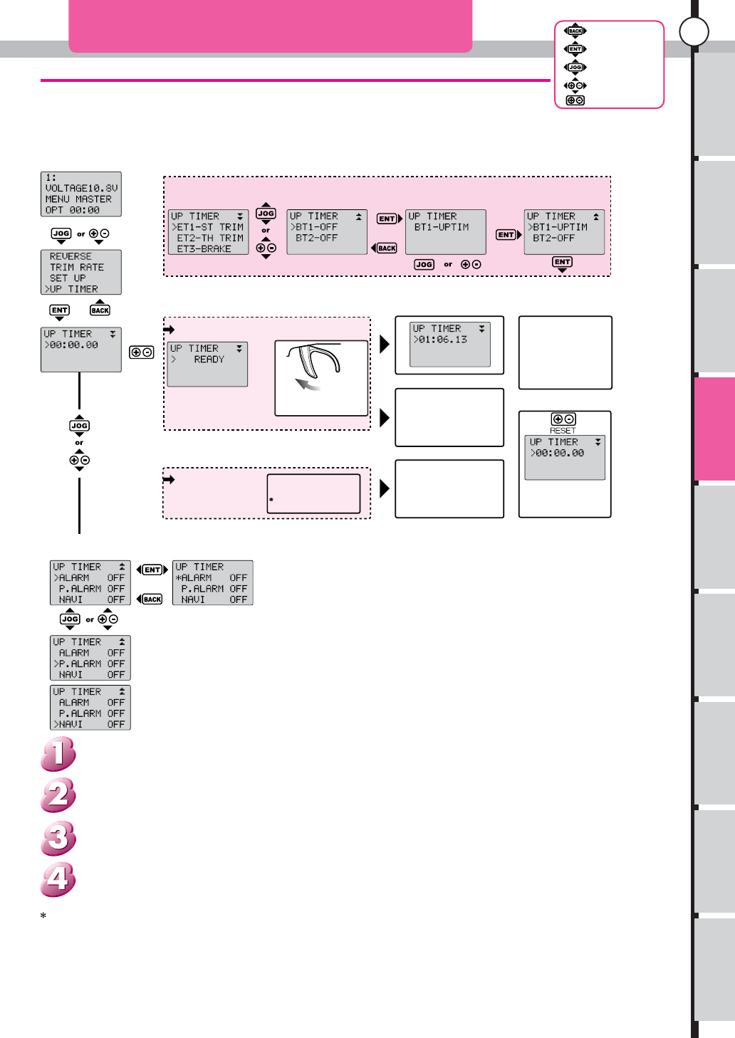
Setup UP timer to use.
UP TIMER
They don’t have an allotment
with an initial situation, a setup
screen is displayed. If assign it to BT1.
Start
Trigger Start
Key Start
"READY" will blink
When time data is
display push reset key
to clear the display
Start when pull the
trigger.
There are two kinds of start methods.
It starts with the
assigned button.
In an example, if BT1 is
pushed, it will start.
It can start, even if it is not a
timer screen.
Start Counting
Stop
Control BT1
It can start, even if
it is not a timer
screen.
Pause
Push Enter key
Operation is possible only on
a timer screen.
It can not change to a setting
screen.
Restart
Control BT1
Or While pause
and Timer screen
was display push
Enter key
Reset
While stop the timer
(Include Pause) push
Reset key.
Can set While timer is stop
(Can not setup while pausing).
Set each item
Alarm is sounded after counting setting time.(Alarm tone can set (See page 29))
Initial Value Off Min.Value 1 min Max.Value 99 min
ALARM
P.ALARM
Can set Pre Alarm before the Alarm
Initial Value OFF Min.Value 1 sec Max.Value 30 sec
NAVI
Set LAP Navigation
Initial Value OFF Min.Value 3.00 sec Max.Value 99.99 sec
When set NAVI, The button assigned to the rise
timer needs reset-after pause operation on a
timer screen to stop in order to function as reset
of NAVI.
Lap navigation function can set the target lap time.
Can start with a button the same as "UP TIMER"
Enter or Back key the cursor will back then push the back key to return at menu
If not ET or BT assign it to lap timer, Setup will be displayed.
From menu list, use Jog dial or "+, -" keys, and select the UP TIMER.
Open the function menu. use Jog dial or "+, -" keys.
[How to open the setup menu]
"UP TIMER" is Simple Timer that add the time. but Can set LAP navigation function also.
DRAF
T
Usage of the
transmitter Features Main Menu Connecting
the receiver Notes on
installing Description Index
62
Back Key
Enter Key
JogDial
+/- Key
Reset
Function Menu
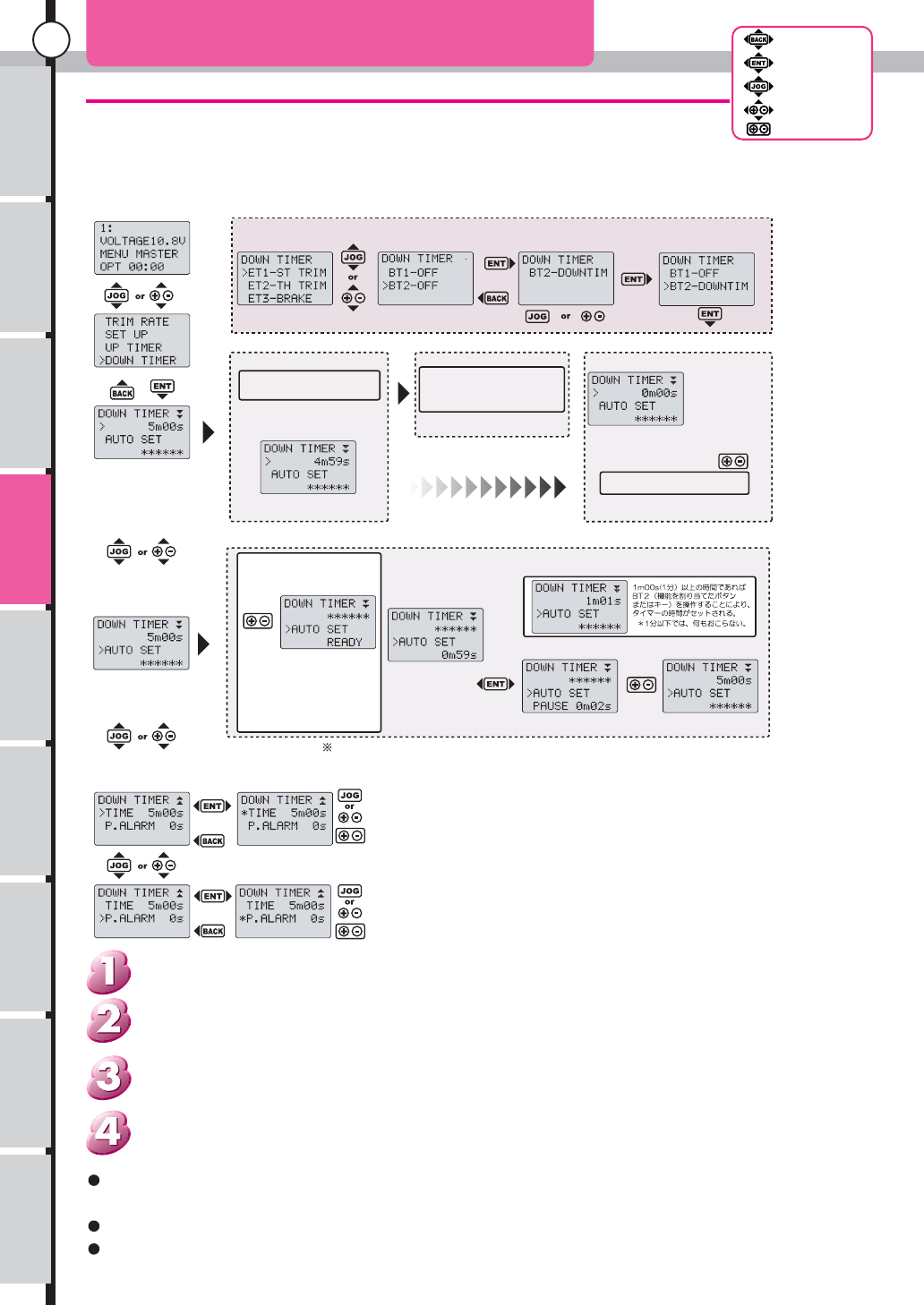
Set Down timer
It is a timer subtracted from time set up.
Use When a timing of fuel refueling of an engine car is measured.
DOWN TIMER
If assign to BT2
Start
Control BT2 to start
it is not necessary to display the
timer screen .
Count indication
Reset start
Control BT2 to reset
then re-start
It is not necessary to display the
timer screen
Stop
When Indicated
0m00s to the
screen, the buzzer
will alarm then
timer will stop
Stop in time
Reset key (push +, - key at the
same time)
it is necessary to display the timer
screen
Auto set
Actually functions to set the time that it took to a down timer.
Ready to start
"READY" will blink
Start at BT2
When push reset button in
Down timer screen. Auto
start function will wait for
start.
While counting
Button
Do a pouse and a start
in turn whenever push
a Enter key.
Need to reset key operation If start Auto set then stop Less than 1 minute.
(It will stop when power-off)
Set up Timer
Initial value 5 min.
Min. value 1 min.
Max value 99 min 59 sec.
Initial value 0 sec.
Min. value 0 sec.
Max value 59 sec.
Pre-alarm
Stop auto set function when
push reset key While pouse.
They don’t have an allotment
with an initial situation, a setup
screen is displayed
Use Auto set, then Run the car till empty the fuel. When set pre alarm, can usable as a
refueling timer
Need to assign any button to use this function.
Can assign the custom tone at alarm of Down timer function.(see page 29)
Subtracted from time set up on Down Timer.
If not ET or BT assign it to lap timer, Setup will be displayed.
From menu list, use Jog dial or "+, -" keys, and select the DOWN TIMER.
Open the function menu. use Jog dial or "+, -" keys.
[How to open the set-up screen.]
D
RAF
T
Usage of the
transmitter Features Main Menu Connecting
the receiver Notes on
installing Description Index
63
Back Key
Enter Key
JogDial
+/- Key
Reset
Function Menu
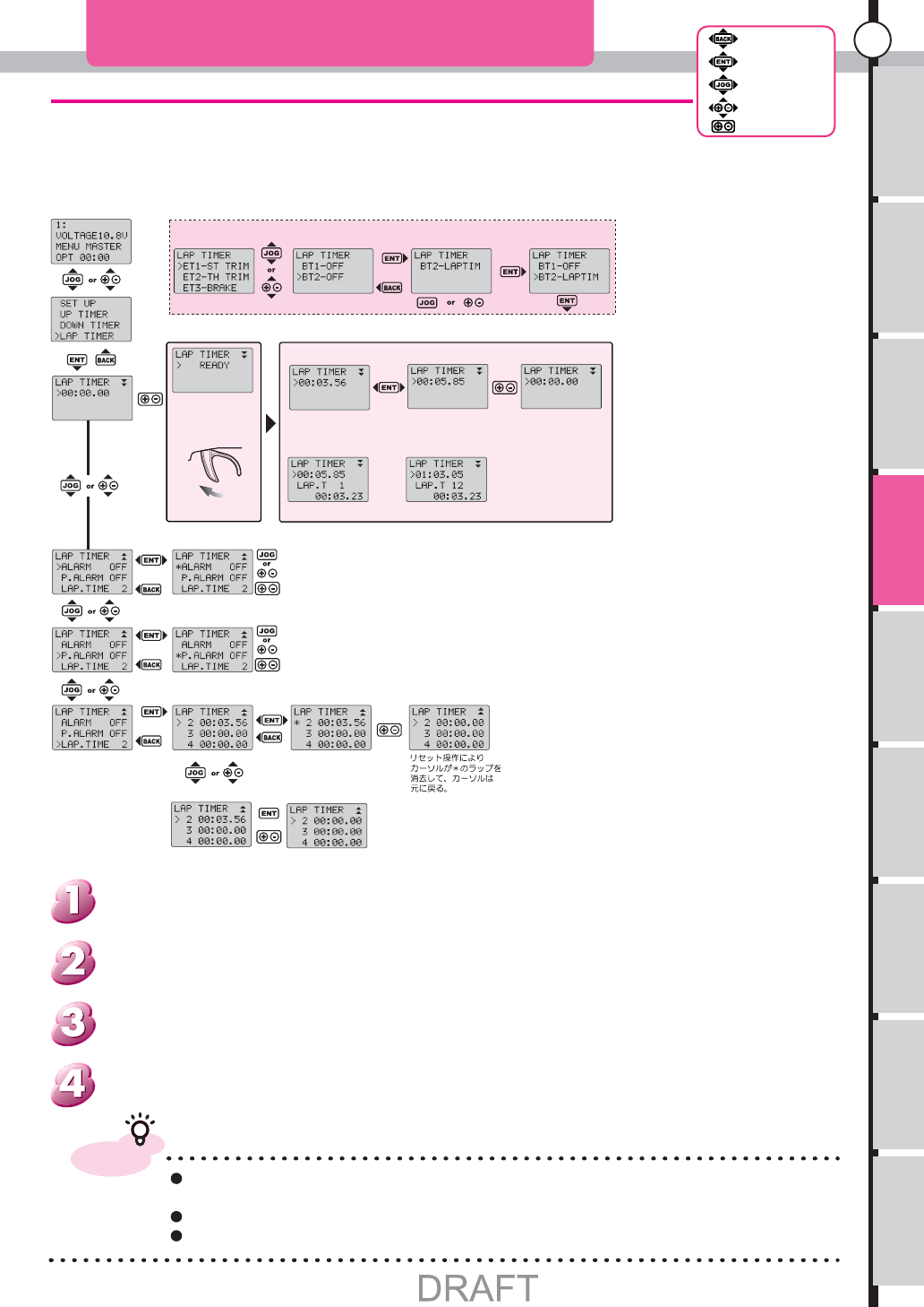
Can count the every lap by using Lap timer.
Set the Lap timer function and measurement point to record the lap.
unestablished any key at an initial situation.
LAP TIMER
Start
"READY" blink
Pull the Trigger,
to start counting
While counting
Counter display
ENT Do
Pause and
restart in turn
Pause
Can not move the
cursor during
pause.
+- When Push the Reset
key during pause. all lap
record will clear.
Lap Records
Start counting when push the
Assigned button.
Stop
Need to set Alarm time.
A timer stops by controlling a
button after time progress.
Alarm Time Setup
Lap Timer Alarm
Pre-Alarm Time
LAP Timer Pre-Alarm
Display Lap Time
Next time start recorded
from displayed LAP
In this case start recording
from LAP 2.
Delete Lap record
Push "ENTER" button to
change the cursor.
Push "ENTER" or "BACK"
button to cancel.
Delete all Lap records.
While push "ENTER" button then Push together the "+ and -"
button. to clear all LAP records
Together
They don’t have an allotment with an initial
situation, a setup screen is displayed.
If assign to BT2
advice
The lap time record at Lap timer will save at same place. but the set up is Independent
at each memory.
Can use custom tone at alarm. (see page 29 and page 30)
Can use 3 kind of timer at same times. (UP Timer, Down Timer, Lap Timer)
Can record till 80 laps. after 80 laps over-write to 81st lap the 1st lap.
If not ET and BT assign it to lap timer, Setup will be displayed.
From menu list, use Jog dial or "+, -" keys, and select the LAP TIMER.
Open the function menu. use Jog dial or "+, -" keys.
[How to open the set-up screen.]
Usage of the
transmitter Features Main Menu
Function Menu
Notes on
installing Description Index
64
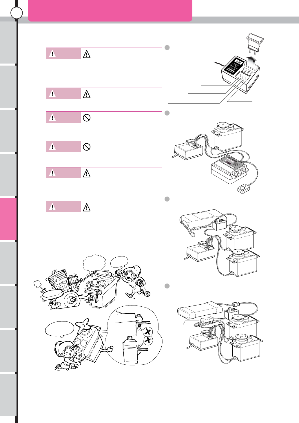
Connecting the Receiver
Steering Servo
7.2V FET Servo
Receiver
Electric
Speed Controler
Connecting the receiver
For an electric-powered car
For a gasoline-powered car (6V servos)
For a gasoline-powered car
(7.2V FET Servos)
5N600mAh
6VNicd Battery Switch Harness
Throttle Servo
Steering Servo
Receiver
6N600mAh
7.2VNicd Battery
Throttle
Servo
Steering
Servo
7V Reguletor
Switch Harness
Receiver
KR-302F
I'm sorry,
I forgot it.
Please give
me grometts
~~~~~~!!
How did you
get this
scratch?
(FET servo + FET ESC)
CH3
Crystal
replacement
CH2
BATT
Switch Harness
ESC or Throttle Servo
CH1
Steering Servo
Antenna Lead
Warning! Be certain to use only KO Propo
genuine FM crystal sets(transmitter
and receiver). Never use crystals
produced by other companies since
such crystals may vary in frequency,
which could lead to misoperation or
out of control.
Warning! Be sure to use grommets and be
sure that the servo is not touching
any metal plates directly. * The
vibrations may damage the servo and
the model may run out of control.
Warning! Be sure to connect all equipment
correctly. If connections are loosened
by vibration,the model may run out of
control.
Caution! Be sure to use genuine KO Propo
products e.g. transmitter,receiver,
ESC and other optional parts.
* We cannot assume any
responsibility for the use of other
companies products with this unit.
Warning! Do not cut or bundle the aerial wire
with other cords. It may result in
decreasing the sensitivity of the
receiver and may result in the model
running out of control.
Caution! Be careful not to reverse the polarity
of the transmitter and the receiver.
Reverse polarity could damage the
units.
Connecting
the receiver
D
RAF
T
Usage of the
transmitter Features Main Menu
Function Menu
Notes on
installing Description Index
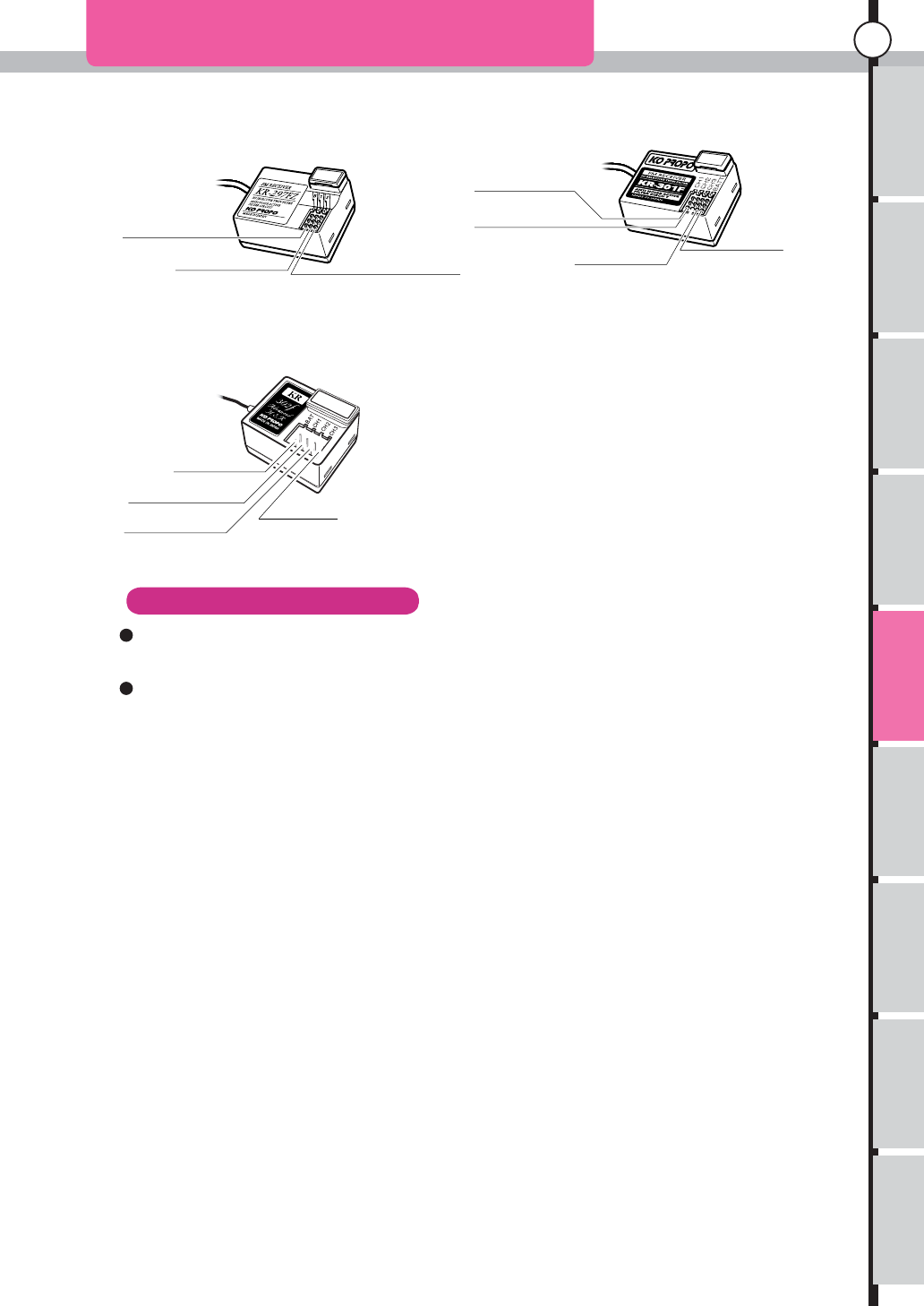
65
Connecting the Receiver
Antenna Lead
Antenna Lead
Antenna Lead
KR-297FZ KR-301F
KR-302F
When the frequency to be used is exchanged in a frequency band.
For changing the frequency band to be used.
The crystal of a transmitter and a receiver is exchanged for the thing of the frequency to be used.
With models of receiver to be used, the order of a row of
each channel and a battery channel changes. Please
connect a connector after a check of a display. Keep in
mind that it does not operate even if it connects Servo and
ESC to a battery channel.
Exchange of a frequency band is possible by exchanging RF module of use. An exchangeable
frequency band is restricted to the frequency band permitted in each country which uses it.
BATT
BATT
Switch Harness
Switch Harness
BATT
Switch Harness
CH3
CH3
CH2
CH2
CH2
ESC or Throttle Servo
ESC or Throttle Servo
ESC or Throttle Servo
CH1
Steering Servo
CH1
Steering Servo
CH1
Steering Servo
About frequency change
Connecting
the receiver
DRAF
T
Usage of the
transmitter Features Main Menu
Function Menu
Connecting
the receiver Description Index
66
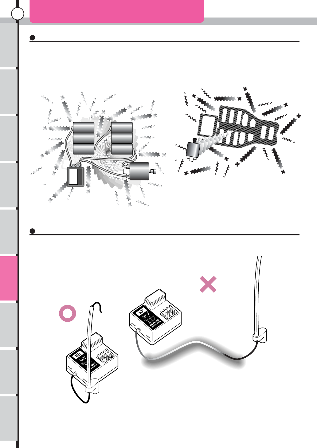
Notes on installing-1
Because this is also part of the
antenna, it is easier to pick up
nearby noise.
The Source of Noise and Electromagnetic Induction (Electric-powered car)
Distance Between the Receiver and Antenna Holder
Metals and carbon can also conduct noise. As
a result, you should never
closely attach the antenna wire to the plate and
carbon chassis.
Notes on
installing
Assume that all areas where large currents are flowing are generating noise!
Locate antenna wires and receivers as far away from the motor, ESC, nicad batteries,and silicone wire as
possible. Noise is a type of radio wave, and therefore is radiated (travel through the air) in the same fashion.
Therefore, locating an antenna near a noise source increases the effect of the noise.
Install the antenna holder as near to the receiver as possible.
The easier it is for the antenna to pick up noise,the sensitivity of the receiver will decrease.
D
RAF
T
Usage of the
transmitter Features Main Menu
Function Menu
Connecting
the receiver Description Index
67
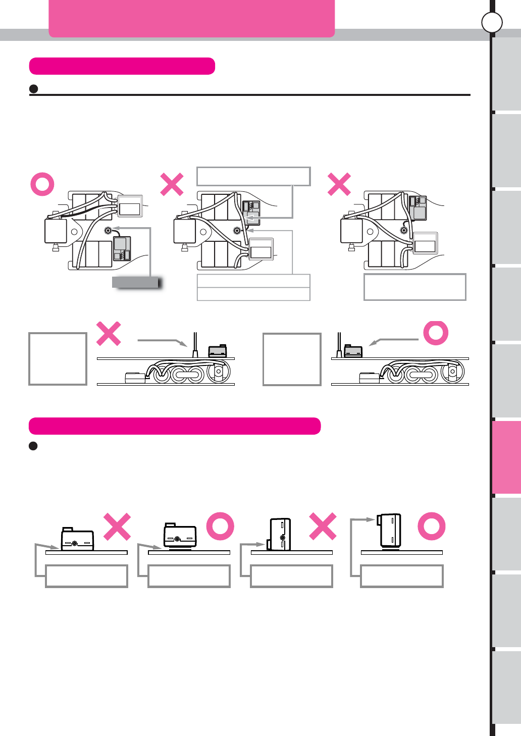
Notes on installing-2
The installation position should be as far as possible from the motor, ESC, nicad batteries, silicone wires or other
noise sources.Especially, do not route the silicone wires next to the receiver. (must not be near to the crystal)
FET servo blue wire (7.2V wire) and switches can also generate noise, position them as far away as possible from
the receiver and the antenna.
When fixing the receiver in place on the chassis or on the "mechanical plate", use two pieces of
double-sided tape, one on top of the other, as that the receiver is cushioned somewhat.
Be sure that the crystal is on the high end when installing the receiver
Notes on Installing the Receiver
Mounting the Receiver (Electric-powered car)
Notes on Installing Position (Do not near the reciever item.)
Notes on
installing
Do not position
the receiver or the
antenna on the top
of the motor or the
nicad batteries.
When mounting the
receiver and antenna on
the "upper deck", position
them as far away from
the nicad batteries and
motor as possible.
Antenna
The silicone wire passes directly
over the receiver.
Do not allow the silicone wires to cross the
antenna. Do not position the antenna opening
or the crystal near the nicad batteries,
motor, or the carbon chassis.
Do not route the wires near the antenna.
Do not mount the receiver
directly on the chassis or
"mechanical deck"
Use two layers of
double-sided tape. Do not position the
crystals on the bottom
Always position the
crystal on the top
DRAF
T
Usage of the
transmitter Features Main Menu
Function Menu
Connecting
the receiver Description Index
68
Notes on installing-3
Bracket Sponge
Piano wire Pipe Pipe
Aluminium holder Aluminium holder Plastic holder
Metal, carbon
(OK if FRP or plastic)
Metal, carbon
(OK if FRP or plastic)
Soldered to
lug board
Metal, carbon
Do not secure
antenna wire
to the plate
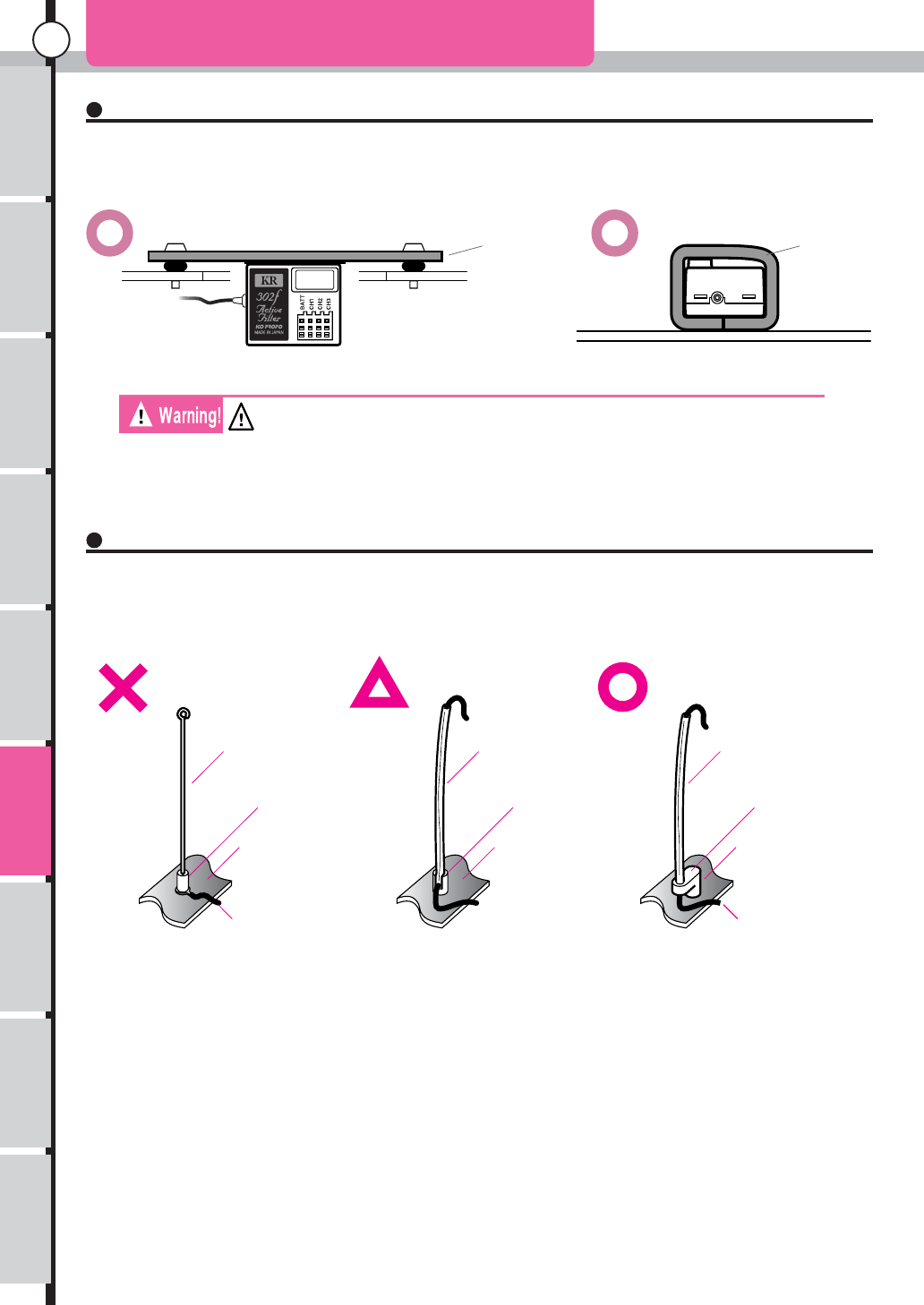
Notes on Installing the Receiver (Gasoline-powered car)
Notes on Antenna Installation
Notes on
installing
Do not secure the receiver on the chassis or the "mechanical deck". Vibrations will cause the receiver to
misfunction and may even cause internal damage to the receiver. Either use the bracket (receiver holder)
provided with the kit, or else cushion the receiver with a sponge like material.
Please follow the instruction as in the illustration below when you mount the antenna holder
to the metal or carbon chassis.When using on FRP or carbon hollow antenna on a racing car,
etc., do not pass the antenna wire through the pipe, allow it to trail away loosely outside.
The exhaust gas of engine carries neither in this place nor the place which
becomes high temperature. * A receiver breaks down and it becomes the cause
of a reckless run.
D
RAF
T

Usage of the
transmitter Features Main Menu
Function Menu
Connecting
the receiver Notes on
installing Description Index
69
Main Specifications
Main Spefcifications
Transmitter KT-303H
Operation method
Number of channels
Transmission Frequency
Neutral pulse
Memory
Supply Voltage
Current consumpion
Wheel+ Triger
3 Channnels
Any Band by changing crystals
within the frequency range
1.5msec
EEPROM
8x AA size dry cel or 8 cells Nicad
Less than 250mA
RF Module RF-501F for KT-303H
Transmission Frequency range
Modulation method
Any frequency range by
switchung RF modules
FM-PPM
Receiver KR-302F
Reception method
Number of channels
Reception frequency
IF frequency
Supply voltage
Dimentions
Weigh
FM-PPM
3 Channels
Any Band by changing crystals
within the frequency range
455KHz
3.5 6.5V
29.3 24.4 16.4mm
12.0 (excluding crystal)
DRAF
T

Usage of the
transmitter Features Main Menu
Function Menu
Connecting
the receiver Notes on
installing Index
70
Description
Description
Terminology used in radio control mode usage.Please refer to the
Index for theterminology or wording of this transmitter.
Analog Servo The general term of a model of machines of the Servo which used a thing of an analog method
for control IC of Servo
Alarm A signal to be famous as a buzzer of a transmitter.
When it is used for a meaning of warning.
Amplifier ESC
ESC Abbreviation of an electric speed controller.
It is a speed controller of a motor to use by electric car.
An amplifier is said.
EEPROM A kind of memory.
Contents written in aren't erased even if switched off.
It is used for data pack in EEPROM others of memory in the main body
Internet The network where the communication network where plural personal computers were
connected to was connected to on a large scale more.
Information dispatch by a homepage and an E-mail are depended on in the world, and
communication can be done.
WEB Site Home Page
AM An electric wave to send from a transmitter
A signal form of an electric wave.
There is FM as another method.
AM is an abbreviated designation in English of an amplitude modulation method.
When that is used,
It is had to match a signal form of transmission and reception machine.
LCD A cable address to mean liquid crystal indication device.
It is used to display letters.
AC Charger A charge container to connect to 100V outlet.
There are many situations to cut more than several hours in charge.
FM A signal form of an electric wave to send from a transmitter.
FM is an abbreviated designation in English of a frequency modulation method
FET An electric field effect transistor.
Loss resistance is small, and, in comparison with a normal transistor, a consumption electric
current of oneself is small, too.
FET Servo FET was used for a motor drive element instead of a conventional transistor, and it is being of
high class Servo.
ET An Abbreviation of electric trim. Besides, a button is abbreviated to BT.
Fast Charger The Charger which charges a nickel-cadmium battery and a nickel metal hydride battery by a
short time.
Carburetor Fuel mixture device, turn number of engines are controlled.
Crystal A component to set frequency of transmission and receiver, It is made from crystal.
Clutch An output axis of an engine and the intermittent continuation device which there is between
gearing devices.
High frequency ESC
(an amplifier)
ESC of the method how frequency to drive a motor is high.
Most are these systems, but the thing which isn't a high frequency system exists in past things.
High frequency (RF)
module
An electric wave is made, and a circuit device to fire can be put on and off.
When a frequency band to use (27MHz .40MHz) is changed, it is had to swap it.
Connector Electric point of contact unit of putting on and off type.
Rubber Grommet The rubber component which protects Servo from vibration, an edge of a Servo case can be
possessed.
Servo The device which converts a management signal of a transmitter into turn machine exercise.
A Servo motor.
Cycle It is space and period of repetition of a certain movement.
CPU IC of a core of a computer used in various uses by digital operation processing.A microcomputer.
It can be called MPU.
Frequency band It is called the place that each frequency gathers, and shine, 27MHz zone (mega Hz), 40MHz
zone.
Receiver (RX) The device which an electric wave of a transmitter is received, and send a control signal forth in
Servo and ESC.
Jog dial A knob for data modification of a turn system not to have a stopper.
If that is controlled every one click, by 1 point can do data modification, but is usable usefully
when numerical value wants to be made a change in at a stretch
Speed controller ESC
Swing Campaign against coming and going between a certain set two points.
Spline Exact location of the servo horn in to the neutral position.
Center Trim Even if the trim is adjusted, overall turning angle point will not be changed.
D
RAF
T

Usage of the
transmitter Features Main Menu
Function Menu
Connecting
the receiver Notes on
installing Index
71
Description
Description
Servo Saver Horn The shock absorbing device that is installed or in place of servo horn.
Transmitter (TX) Hand set that transmitter signal.
Turning Angle (Travel) Turning angle of the servo horn.
Channel (CH) Number of Servo which can be controlled with a transmitter one by one.
Or it is a number of that individual signal
Data Pack It is the module which had memory for enlargement built-in.
Usable model memory can be increased.
Digital Servo The general term of a model of machines of the Servo which used a thing of a digital system for
control IC of Servo.
Delay Act slowly.
DC Charger The Charger which uses direct current for power supplies such as 12V battery or 12V
stabilization power supply.
Duty It is the ratio of two movement.
Travel It is a rudder angle, movement volume.
Trigger Control mechanism of a transmitter. A piece pulled with a finger to control the speed or brakes.
Trim The device which adjusts a neutral position of each channel signal.
7.2V Servo The Servo that a motor becomes the other power supply.
By a KO PROPO original system, it is expected that a power supply is taken out of a power
supply for power (7.2V) in the case of an electric car
NiCad (Ni-cd) It is different from a dry cell,
The battery which it is charged repeatedly, and can be used.
There are NiMH or lithium ion as the battery which it is charged, and can be used repeatedly
elsewhere
Neutral The situation that separated a hand from a stick of a transmitter or a position of Servo Horne at
that time.
27Mhz It is for one of the frequency band that it can use by radio control, ground, water model, and there
are 12 belts.
Noise An electric noise.
For a kind of electric wave, it makes it jumps into a receiver and malfunction.
Band plate It is frequency and is selected with crystal glass.
It can make a change by crystal glass exchange in the same frequency band.
Band It is frequency and is selected with crystal glass.
It can make a change by crystal glass exchange in the same frequency band
Backlight Because themselves don't emit light LCD (a liquid crystal display), visibility isn't good by the time
if it is dark.
It is the lamp which is installed in the backside of liquid crystal to solve this (the emission of light
source)
Dead Band The field where Servo doesn't react to even if it controls foil and trigger.
VR It means the volume that detects the position of the stick.
Fail safe adaptor When it receives an interference electric wave, it is the device which it fixes Servo Horne at the
position that a computer set up beforehand, and prevent reckless driving.
Push rod The stick thing which is used for linkage.
Preset Will set up a position in advance
PC interface It is an adapter it converts a signal into, and to be connected to do setting of a transmitter with a
PC.
Discharger The circuit device which makes you discharge a residual quantity of a charge type battery of
NiCad forcibly.
Wheel Mechanism of the transmitter which it turns it from side to side, and control a steering.
Pumping Effect Intermittent breaking action.
Home Page It says the place where it mentioned a certain information in on Internet.
It can look by software on a personal computer called a Web browser.
Machine plate The board which installs receiver Servo on a chassis of a car.
Mega Hz (MHz) 1000Hz =1 KHz (a kilohertz) 1000KHz =1MHz.
Memory In a personal computer, it is used for a meaning called the preservation place in which
information is stored temporarily. Although the information on the memory in this case will be
lost if a power supply is shut off, the memory used for a transmitter etc. is called non-volatilized
memory, and even if it shuts off a power supply, it holds information.
40Mhz One of the frequency band that it can use by radio control. Eight bands for ground model. There
are five bands for sky model.
Linkage Servo and connection mechanism to connect each mechanism to of a model.
Reset Return setting contents of setting numerical value to an initial situation
Regulator The circuit which stabilizes the input voltage to the necessary voltage.
Response It is time before machinery of the receiver side reacting since it controls a transmitter.
Width The thing of width which operates by ABS or Throttle Acceleration.
DRAF
T

Usage of the
transmitter Features Main Menu
Function Menu
Connecting
the receiver Notes on
installing Description
72
Index
D
RAF
T

Usage of the
transmitter Features Main Menu
Function Menu
Connecting
the receiver Notes on
installing Description
73
Index
DRAF
T

Usage of the
transmitter Features Main Menu
Function Menu
Connecting
the receiver Notes on
installing Description Index
74
DRAFT