Kyosho of America SYNCROEX6 Radio control transmitter User Manual 82030 Syncro EX 6 manual EN
Kyosho Corporation of America Radio control transmitter 82030 Syncro EX 6 manual EN
Contents
- 1. 06_1_Users_Manual_rev2
- 2. 06_2_Users_Manual_rev2
- 3. 06_3_Users_Manual_rev2
06_1_Users_Manual_rev2
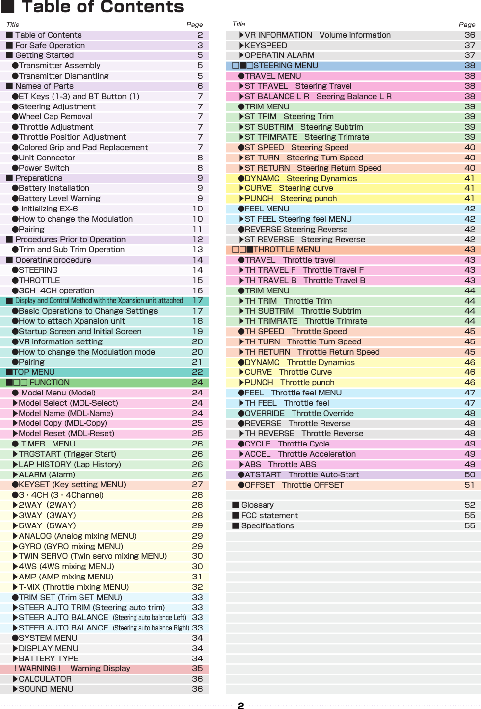
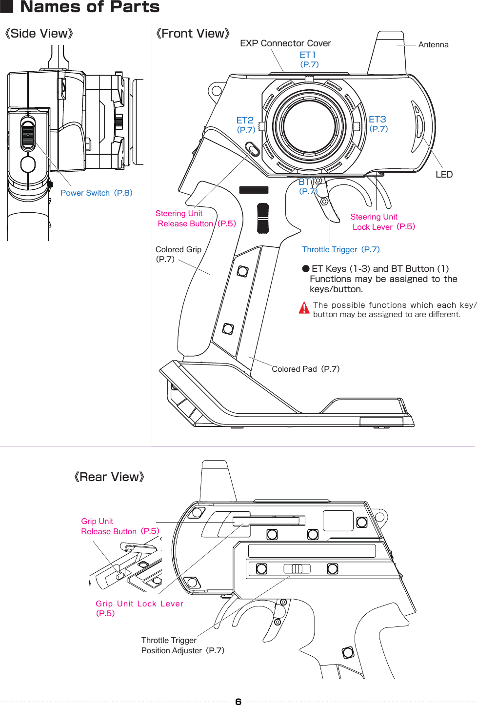
![①① ②②③③①① ②②③③①①②②5■ Getting StartedInsert the Grip Unit into the Master Unit, then attach the Steering Unit.Detach the Steering Unit, then detach the Master Unit.● Transmitter Assembly ● Transmitter Dismantling1.1.2.2.3.3.Remove the connector cover before use.If storing the transmitter in dismantled form, please remember to attach the connector covers. (separately available option: Kondo Kagaku Co., Ltd.)Assembly may dier with the included set contents.[Legend] P:Point :NoticeSteering Unit Release ButtonSteering Unit Release ButtonSteering Unit Lock LeverSteering Unit Lock LeverGrip Unit Lock Lever Grip Unit Release ButtonGrip UnitMaster UnitMaster UnitSteering UnitSteering Unit※Assembled※ Depending on the model, expansion unit has been installed at the factory.](https://usermanual.wiki/Kyosho-of-America/SYNCROEX6.06-1-Users-Manual-rev2/User-Guide-2656149-Page-5.png)
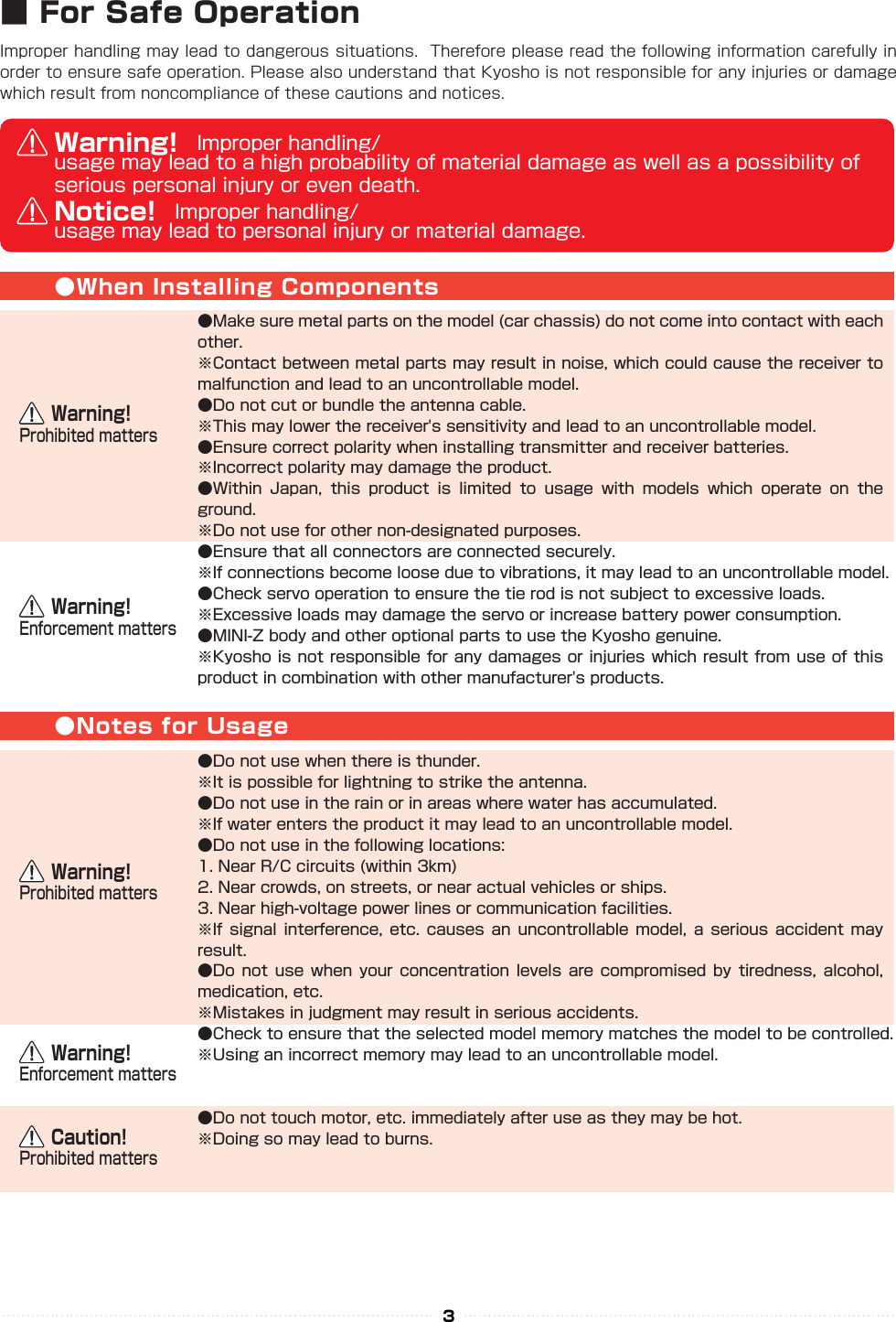
![The tabs on the colored grip and pad are to be inserted into holes. Note the direction.Make sure the battery box or battery pack is removed before replacing the colored grip and pad.Note direction of the of the colored grip and pad7●Steering Wheel Adjustment●Throttle Trigger Adjustment●Wheel Cap Remove●Throttle Trigger Position Adjustment●Colored Grip and Pad Replacement● ET Keys (1-3) and BT Button (1)Functions may be assigned to the keys/button.The possible functions which each key/button may be assigned to are dierent.Colored grip pad (optional: Kondo Kagaku Co., Ltd.) and Large/small grip pad options are available.Remove the two screws on each side of the grip to detach the grip plates, then attach the colored grip and pad.《How to change》Adjust the tension of the steering wheel spring.Insert a 1.5mm hex wrench referring to the image below. Rotate clockwise to increase tension and counterclockwise to decrease it.[How to Adjust]Hex WrenchExcessive counterclockwise rotation will result in the wheel being unable to return to neutral position. In this case, rotate clockwise until the wheel returns to neutral.Temperature and aging, because it may become loose by the strong impact or the like, it is recommended that you adhere to such cases. In the case where there is a thing that would loose still, please contact the user consultation room.Insert Wheel Cap Remover to the wheel cap spoke.Pull up Wheel cap remover with Wheel Cap.Since the screw will appear If you remove the handle cap, it will be able to remove the steering wheel by removing the screw.Adjust the position and angle of the brake trigger to your preferences.Loosen the hex screws on the throttle trigger with a 1.5mm hex wrench. Freely adjust the brake trigger position. Tighten the hex screws to secure.[How to Adjust]Throttle TriggerBrake Trigger Hex ScrewsBall JointThe position of the throttle trigger may be adjusted to match the user's hands. Loosen two screws on the rear side of the transmitter. Slide the Throttle Trigger Position Adjuster as desired. Tighten the loosened screws to secure.[How to Adjust]ScrewsThrottle TriggerPosition Adjuster](https://usermanual.wiki/Kyosho-of-America/SYNCROEX6.06-1-Users-Manual-rev2/User-Guide-2656149-Page-7.png)
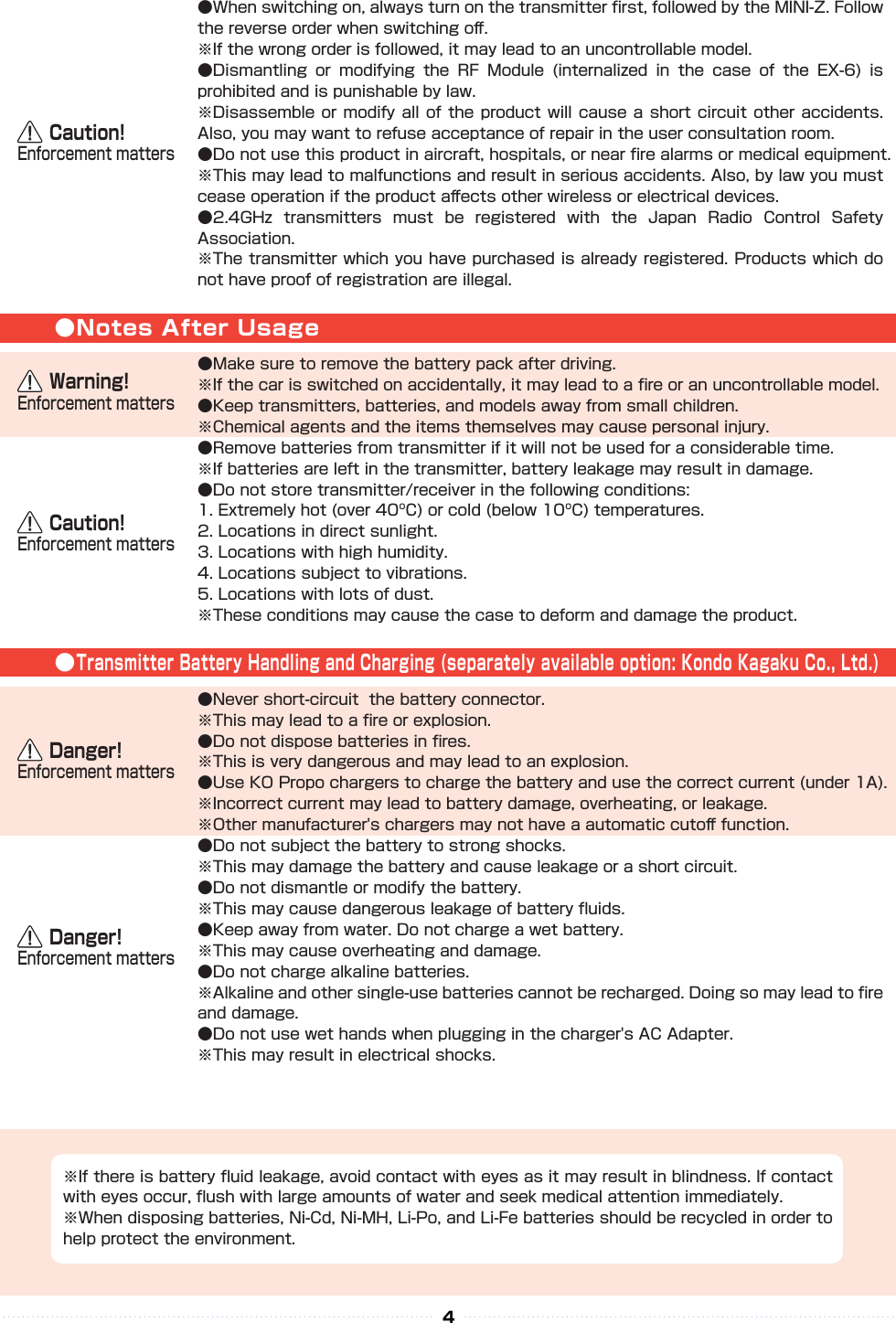
![ST TURN 50%ST RETURN 100%ターンスピードリターンスピードST SPEED スピードST TURN 100%ST RETURN 100%ターンスピードリターンスピードST SPEED スピードST TURN 50%ST RETURN 100%ターンスピードリターンスピードST SPEED スピードST TURN 100%ST RETURN 100%ターンスピードリターンスピードST SPEED スピード17【 Basic Operation 1: Selecting from a Menu 】 This explanation uses [Steering] as an example. ① Use the R(>) key to move the cursor over [Steering]. ② Press the ENTER key to change to the Steering Menu screen.【 Basic Operation 2: Changing a Setting Value 】 This explanation uses [TURN 1] on the Steering Speed screen as an example. ① Use R(>) key to move the cursor over the 100% value next to [ST TURN]. ② Press ENTER key to select it for modication. ③ Once selected, the cursor will blink. Now use the L(<)key+R(>)key to change the value. ④ After changing the value, press the ENTER key again to conrm the change.■ Display and Control Method with the Xpansion unit attached● Basic Operations to Change SettingsBACK Key L( < )Key R( > )KeyCommand ButtonCommunication portUsed for rmware upgrading.Used for rmware upgrading and ICS communication.ENT KeyControlling of the setting adjustments is done via the L(<) key, R(>)key, ENTER(ENT) key, and BACK key.OperationENT Key: Selecting item to be modied; Conrming a change after a setting change. L( < )Key: Used to move cursor between menu choices and to change a setting value. Lowering a value (for L/R cases: raising toward L); Return to a previous menu item.R( > )Key: Used to move cursor between menu choices and to change a setting value. Raising value (for L/R cases: raising toward R); Proceed to next menu item.BACK Key:Returning to previous screen; Canceling changeL(<) key + R(>) key Pressing simultaneously: Resets the value to default setting.](https://usermanual.wiki/Kyosho-of-America/SYNCROEX6.06-1-Users-Manual-rev2/User-Guide-2656149-Page-17.png)
![AB18② Attach the monitor bracket to the master unit. ※[A▼]mark to the steering side② Attach the monitor bracket to the master unit. ※ Apply [B ▼] mark to the steering side① Attach the monitor base parallel to Xpansion unit. ※ Factory setting.※ The disconnecting method is the same for side and front positions.① Attach the monitor base at a right angle to Xpansion Unit. ※ Dierent Factory setting.Attention to the marker.Attention to the marker.M2.6-6BHM2.6-6BHx 2x 2x 4x 4TP2.6-8BHSelf tapping screwsTP2.6-8BHSelf tapping screwsConnect the wire of the Xpansion unit to the master unit.Connect the wire of the Xpansion unit to the master unit.③ Attach expansion unit to the master unit.③ Attach the Xpansion unit to the master unit. ※ Attach the monitor base and bracket as shown in gure A ③ .1.While pushing the monitor-based apart.2.Slide the Xpansion like shown in the gure below and take o.While matching the edge of the base with the dent of the bracket, slide it until the Xpansion unit locks.A ▼:setting to the frontXpansion unit can be mounted facing the front or the side. The factory setting is mounted to the front.▼ B:when mounting sidewaysHow to disconnect the Xpansion unit.When connecting or disconnecting the Xpansion unit to EX-6, please switch o the EX-6.Be careful to not misuse the M2.6-6BH and TP2.6-8BH screws.Xpansioun unit can be mounted in two different directions using the monitor base and bracket.P● Installation of expansion unit1 2※Depending on the model, expansion unit has been installed at the factory.](https://usermanual.wiki/Kyosho-of-America/SYNCROEX6.06-1-Users-Manual-rev2/User-Guide-2656149-Page-18.png)