Kyosho of America SYNCROEX6 Radio control transmitter User Manual 82030 Syncro EX 6 manual EN
Kyosho Corporation of America Radio control transmitter 82030 Syncro EX 6 manual EN
Contents
- 1. 06_1_Users_Manual_rev2
- 2. 06_2_Users_Manual_rev2
- 3. 06_3_Users_Manual_rev2
06_1_Users_Manual_rev2

THE FINEST RADIO CONTROL MODELS
R
*Specifications are subject to be changed without prior notice!
DIGITAL PROPORTIONAL SYSTEMDIGITAL PROPORTIONAL SYSTEM
Before beginning assembly, please read these instructions thoroughly.
© Copyright 2015 KYOSHO CORPORATION / 禁無断転載複製
82030-T01
Instruction Manual

2
Title Title
Page Page
■ Table of Contents
■ Table of Contents 2
■ For Safe Operation 3
■ Getting Started 5
●Transmitter Assembly 5
●Transmitter Dismantling 5
■ Names of Parts 6
●ET Keys (1-3) and BT Button (1) 7
●Steering Adjustment 7
●Wheel Cap Removal 7
●Throttle Adjustment 7
●Throttle Position Adjustment 7
●Colored Grip and Pad Replacement 7
●Unit Connector 8
●Power Switch 8
■ Preparations 9
●Battery Installation 9
●Battery Level Warning 9
● Initializing EX-6 10
●How to change the Modulation 10
●Pairing 11
■ Procedures Prior to Operation 12
●Trim and Sub Trim Operation 13
■ Operating procedure 14
●STEERING 14
●THROTTLE 15
●3CH 4CH operation 16
■
Display and Control Method with the Xpansion unit attached
17
●Basic Operations to Change Settings 17
●How to attach Xpansion unit 18
●Startup Screen and Initial Screen 19
●VR information setting 20
●How to change the Modulation mode 20
●Pairing 21
■TOP MENU 22
■□□ FUNCTION 24
● Model Menu (Model) 24
▶Model Select (MDL-Select) 24
▶Model Name (MDL-Name) 24
▶Model Copy (MDL-Copy) 25
▶Model Reset (MDL-Reset) 25
● TIMER MENU 26
▶TRGSTART (Trigger Start) 26
▶LAP HISTORY (Lap History) 26
▶ALARM (Alarm) 26
●KEYSET (Key setting MENU) 27
●3・4CH (3・4Channel) 28
▶2WAY(2WAY) 28
▶3WAY(3WAY) 28
▶5WAY(5WAY) 29
▶ANALOG (Analog mixing MENU) 29
▶GYRO (GYRO mixing MENU) 29
▶TWIN SERVO (Twin servo mixing MENU) 30
▶4WS (4WS mixing MENU) 30
▶AMP (AMP mixing MENU) 31
▶T-MIX (Throttle mixing MENU) 32
●TRIM SET (Trim SET MENU) 33
▶STEER AUTO TRIM (Steering auto trim) 33
▶STEER AUTO BALANCE
(Steering auto balance Left)
33
▶STEER AUTO BALANCE
(Steering auto balance Right)
3 3
●SYSTEM MENU 34
▶DISPLAY MENU 34
▶BATTERY TYPE 34
!WARNING! Warning Display 35
▶CALCULATOR 36
▶SOUND MENU 36
▶VR INFORMATION Volume information 36
▶KEYSPEED 37
▶OPERATIN ALARM 37
□■□STEERING MENU 38
●TRAVEL MENU 38
▶ST TRAVEL Steering Travel 38
▶ST BALANCE L R Seering Balance L R 38
●TRIM MENU 39
▶ST TRIM Steering Trim 39
▶ST SUBTRIM Steering Subtrim 39
▶ST TRIMRATE Steering Trimrate 39
●ST SPEED Steering Speed 40
▶ST TURN Steering Turn Speed 40
▶ST RETURN Steering Return Speed 40
●DYNAMC Steering Dynamics 41
▶CURVE Steering curve 41
▶PUNCH Steering punch 41
●FEEL MENU 42
▶ST FEEL Steering feel MENU 42
●REVERSE Steering Reverse 42
▶ST REVERSE Steering Reverse 42
□□■THROTTLE MENU 43
●TRAVEL Throttle travel 43
▶TH TRAVEL F Throttle Travel F 43
▶TH TRAVEL B Throttle Travel B 43
●TRIM MENU 44
▶TH TRIM Throttle Trim 44
▶TH SUBTRIM Throttle Subtrim 44
▶TH TRIMRATE Throttle Trimrate 44
●TH SPEED Throttle Speed 45
▶TH TURN Throttle Turn Speed 45
▶TH RETURN Throttle Return Speed 45
●DYNAMC Throttle Dynamics 46
▶CURVE Throttle Curve 46
▶PUNCH Throttle punch 46
●FEEL Throttle feel MENU 47
▶TH FEEL Throttle feel 47
●OVERRIDE Throttle Override 48
●REVERSE Throttle Reverse 48
▶TH REVERSE Throttle Reverse 48
●CYCLE Throttle Cycle 49
▶ACCEL Throttle Acceleration 49
▶ABS Throttle ABS 49
●ATSTART Throttle Auto-Start 50
●OFFSET Throttle OFFSET 51
■ Glossary 52
■ FCC statement 55
■ Specications 55

Improper handling may lead to dangerous situations. Therefore please read the following information carefully in
order to ensure safe operation. Please also understand that Kyosho is not responsible for any injuries or damage
which result from noncompliance of these cautions and notices.
●When Installing Components
●Notes for Usage
●Make sure metal parts on the model (car chassis) do not come into contact with each
other.
※Contact between metal parts may result in noise, which could cause the receiver to
malfunction and lead to an uncontrollable model.
●Do not cut or bundle the antenna cable.
※This may lower the receiver's sensitivity and lead to an uncontrollable model.
●Ensure correct polarity when installing transmitter and receiver batteries.
※Incorrect polarity may damage the product.
●Within Japan, this product is limited to usage with models which operate on the
ground.
※Do not use for other non-designated purposes.
●Ensure that all connectors are connected securely.
※If connections become loose due to vibrations, it may lead to an uncontrollable model.
●Check servo operation to ensure the tie rod is not subject to excessive loads.
※Excessive loads may damage the servo or increase battery power consumption.
●MINI-Z body and other optional parts to use the Kyosho genuine.
※Kyosho is not responsible for any damages or injuries which result from use of this
product in combination with other manufacturer's products.
●Do not use when there is thunder.
※It is possible for lightning to strike the antenna.
●Do not use in the rain or in areas where water has accumulated.
※If water enters the product it may lead to an uncontrollable model.
●Do not use in the following locations:
1. Near R/C circuits (within 3km)
2. Near crowds, on streets, or near actual vehicles or ships.
3. Near high-voltage power lines or communication facilities.
※If signal interference, etc. causes an uncontrollable model, a serious accident may
result.
●Do not use when your concentration levels are compromised by tiredness, alcohol,
medication, etc.
※Mistakes in judgment may result in serious accidents.
●Check to ensure that the selected model memory matches the model to be controlled.
※Using an incorrect memory may lead to an uncontrollable model.
●Do not touch motor, etc. immediately after use as they may be hot.
※Doing so may lead to burns.
Warning! Improper handling/
usage may lead to a high probability of material damage as well as a possibility of
serious personal injury or even death.
Notice! Improper handling/
usage may lead to personal injury or material damage.
Warning!
Enforcement matters
Warning!
Prohibited matters
Warning!
Prohibited matters
Warning!
Enforcement matters
Caution!
Prohibited matters
3
■ For Safe Operation
●Notes After Usage
●
Transmitter Battery Handling and Charging (separately available option: Kondo Kagaku Co., Ltd.)
Caution!
Enforcement matters
Caution!
Enforcement matters
Danger!
Enforcement matters
Danger!
Enforcement matters
●When switching on, always turn on the transmitter first, followed by the MINI-Z. Follow
the reverse order when switching off.
※If the wrong order is followed, it may lead to an uncontrollable model.
●Dismantling or modifying the RF Module (internalized in the case of the EX-6) is
prohibited and is punishable by law.
※Disassemble or modify all of the product will cause a short circuit other accidents.
Also, you may want to refuse acceptance of repair in the user consultation room.
●Do not use this product in aircraft, hospitals, or near fire alarms or medical equipment.
※This may lead to malfunctions and result in serious accidents. Also, by law you must
cease operation if the product affects other wireless or electrical devices.
●2.4GHz transmitters must be registered with the Japan Radio Control Safety
Association.
※The transmitter which you have purchased is already registered. Products which do
not have proof of registration are illegal.
●Make sure to remove the battery pack after driving.
※If the car is switched on accidentally, it may lead to a fire or an uncontrollable model.
●Keep transmitters, batteries, and models away from small children.
※Chemical agents and the items themselves may cause personal injury.
●Remove batteries from transmitter if it will not be used for a considerable time.
※If batteries are left in the transmitter, battery leakage may result in damage.
●Do not store transmitter/receiver in the following conditions:
1. Extremely hot (over 40ºC) or cold (below 10ºC) temperatures.
2. Locations in direct sunlight.
3. Locations with high humidity.
4. Locations subject to vibrations.
5. Locations with lots of dust.
※These conditions may cause the case to deform and damage the product.
●Never short-circuit the battery connector.
※This may lead to a fire or explosion.
●Do not dispose batteries in fires.
※This is very dangerous and may lead to an explosion.
●Use KO Propo chargers to charge the battery and use the correct current (under 1A).
※Incorrect current may lead to battery damage, overheating, or leakage.
※Other manufacturer's chargers may not have a automatic cutoff function.
●Do not subject the battery to strong shocks.
※This may damage the battery and cause leakage or a short circuit.
●Do not dismantle or modify the battery.
※This may cause dangerous leakage of battery fluids.
●Keep away from water. Do not charge a wet battery.
※This may cause overheating and damage.
●Do not charge alkaline batteries.
※Alkaline and other single-use batteries cannot be recharged. Doing so may lead to fire
and damage.
●Do not use wet hands when plugging in the charger's AC Adapter.
※This may result in electrical shocks.
※If there is battery fluid leakage, avoid contact with eyes as it may result in blindness. If contact
with eyes occur, flush with large amounts of water and seek medical attention immediately.
※When disposing batteries, Ni-Cd, Ni-MH, Li-Po, and Li-Fe batteries should be recycled in order to
help protect the environment.
Warning!
Enforcement matters
4
①① ②②
③
③
①① ②②
③③
①①
②
②
5
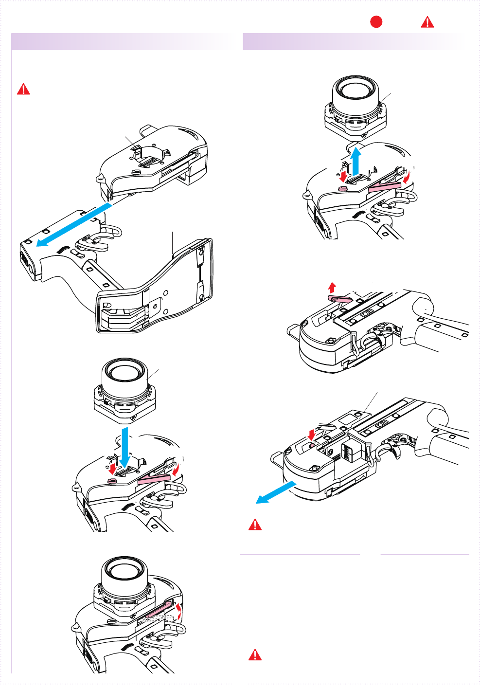
■ Getting Started
Insert the Grip Unit into the Master Unit, then attach
the Steering Unit.
Detach the Steering Unit, then detach the Master
Unit.
● Transmitter Assembly ● Transmitter Dismantling
1.
1.
2.
2.
3.
3.
Remove the connector cover before use.
If storing the transmitter in dismantled form,
please remember to attach the connector covers.
(separately available option: Kondo Kagaku Co., Ltd.)
Assembly may dier with the included set contents.
[Legend] P:Point :Notice
Steering Unit Release Button
Steering Unit Release Button
Steering Unit Lock Lever
Steering Unit Lock Lever
Grip Unit Lock Lever
Grip Unit Release Button
Grip Unit
Master Unit
Master Unit
Steering Unit
Steering Unit
※Assembled
※ Depending on the model, expansion
unit has been installed at the factory.
6
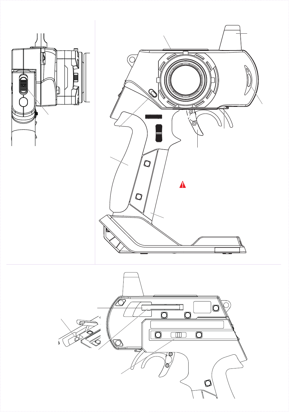
Antenna
EXP Connector Cover
Power Switch(P.8)
LED
Steering Unit
Release Button(P.5)
Colored Grip
(P.7)
Colored Pad(P.7)
● ET Keys (1-3) and BT Button (1)
Functions may be assigned to the
keys/button.
Steering Unit
Lock Lever(P.5)
Throttle Trigger(P.7)
Grip Unit Lock Lever
(P.5)
Grip Unit
Release Button(P.5)
Throttle Trigger
Position Adjuster(P.7)
ET1
(P.7)
BT1
(P.7)
ET2
(P.7)
ET3
(P.7)
■ Names of Parts
《Front View》《Side View》
《Rear View》
The possible functions which each key/
button may be assigned to are dierent.
The tabs on the colored grip and pad are to be inserted
into holes. Note the direction.
Make sure the battery box or battery pack is removed
before replacing the colored grip and pad.
Note direction of the of the colored grip and pad
7
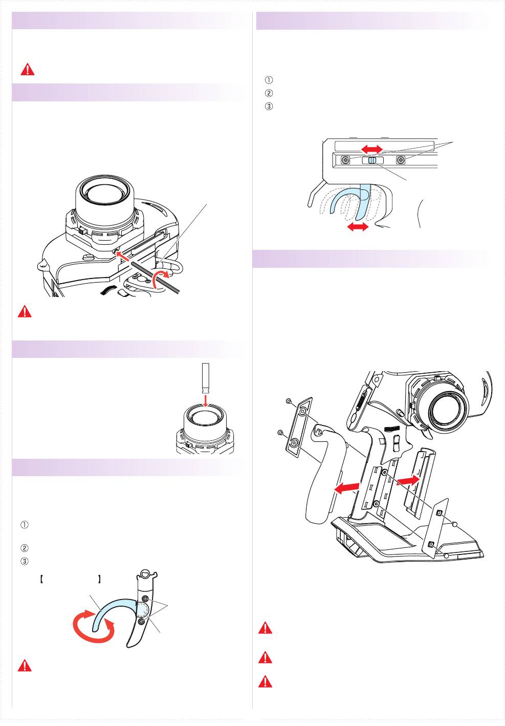
●Steering Wheel Adjustment
●Throttle Trigger Adjustment
●Wheel Cap Remove
●
Throttle Trigger Position Adjustment
●
Colored Grip and Pad Replacement
● ET Keys (1-3) and BT Button (1)
Functions may be assigned to the keys/button.
The possible functions which each key/button may be
assigned to are dierent.
Colored grip pad (optional: Kondo Kagaku Co., Ltd.)
and Large/small grip pad options are available.
Remove the two screws on each side of the grip to
detach the grip plates, then attach the colored grip
and pad.
《How to change》
Adjust the tension of the steering wheel spring.
Insert a 1.5mm hex wrench referring to the image below.
Rotate clockwise to increase tension and counterclockwise to
decrease it.
[How to Adjust]
Hex Wrench
Excessive counterclockwise rotation will result in the wheel being
unable to return to neutral position. In this case, rotate clockwise
until the wheel returns to neutral.
Temperature and aging, because it may become loose by the
strong impact or the like, it is recommended that you adhere to
such cases. In the case where there is a thing that would loose
still, please contact the user consultation room.
Insert Wheel Cap Remover to the wheel cap spoke.
Pull up Wheel cap remover with Wheel Cap.
Since the screw will appear If you remove
the handle cap, it will be able to remove the
steering wheel by removing the screw.
Adjust the position and angle of the brake trigger to your
preferences.
Loosen the hex screws on the throttle trigger with a 1.5mm
hex wrench.
Freely adjust the brake trigger position.
Tighten the hex screws to secure.
[How to Adjust]
Throttle Trigger
Brake Trigger Hex Screws
Ball Joint
The position of the throttle trigger may be adjusted to match the
user's hands.
Loosen two screws on the rear side of the transmitter.
Slide the Throttle Trigger Position Adjuster as desired.
Tighten the loosened screws to secure.
[How to Adjust]
Screws
Throttle Trigger
Position Adjuster
8
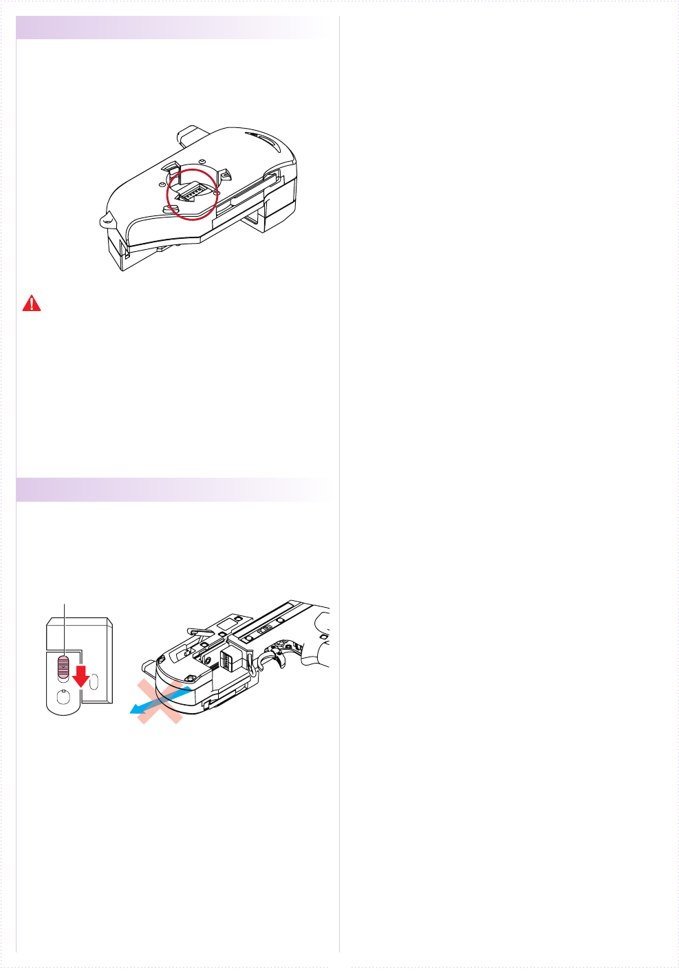
●Unit Connector
●Power Switch
This product may be dismantled and therefore each unit
features their respective connectors. Dirty or damaged
connectors may result in malfunctions, so please handle them
carefully.
Do not touch the unit connectors with your ngers. If connectors
become corroded due to grime, they may become inoperable. If
storing the transmitter in dismantled form. After prolonged use, a
black residue may build up on the connectors. Use cotton swabs
dipped in cleaning alcohol to remove. In addition, we have repaired
in our user consultation room.
This product features a safety lock. The Master Unit and Grip
Unit cannot be detached when the Power Switch is in the ON
position. Turn off the transmitter before dismantling.
Power Switch
①①
①
①
②
②
②
②
9
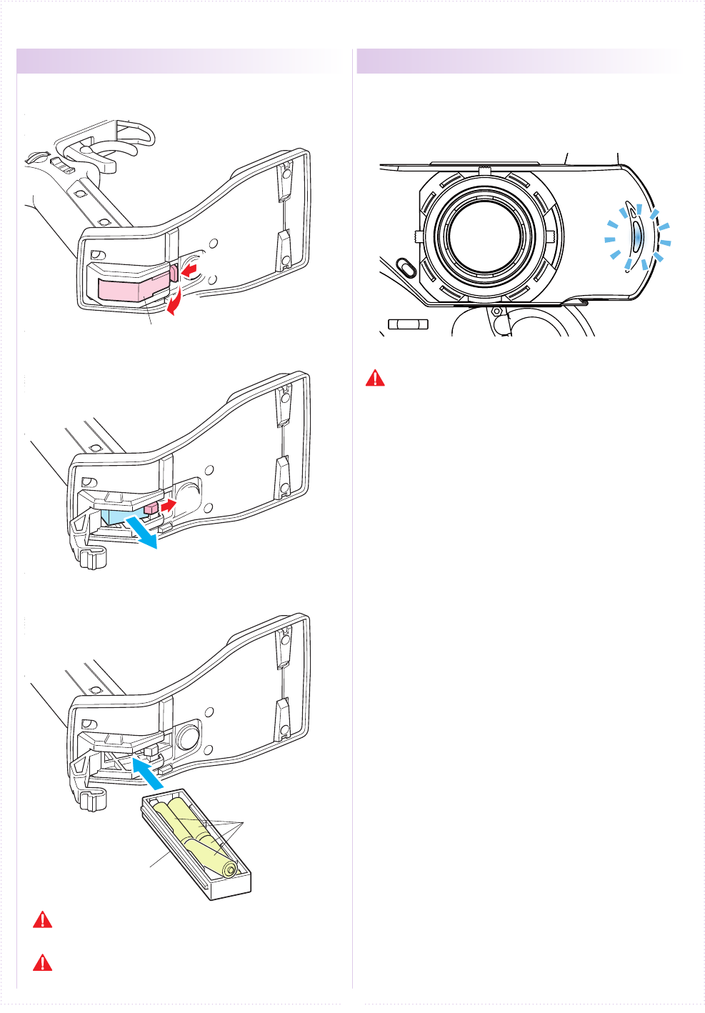
■ Preparations
●Battery Installation ● Battery Level Warning
Battery Box
1.
2.
3.
R03/AAA/UM4
Batteries (4pcs.)
Battery Box Cover
Press the tab on the bottom of the transmitter to open
battery box cover.
Remove the lock to pull out battery
box.
Install four R03/AAA/UM4 alkaline
batteries while noting their polarity,
then replace
battery box.
Use batteries which have adequate remaining capacity. Weak
batteries mean lower transmitting power and may result in
malfunctions.
Do not install Ni-Cd or Ni-MH batteries in the battery box.
(These may cause the battery connectors to corrode.)
A warning will be displayed with the LED ashing and
an alarm will sound when battery voltage is less 4v.
When you see this warning, stop your model in a safe
area, turn it o and install new transmitter batteries.
If the Xpansion unit is not assembled or
used, do not use the LiFe/LiPo battery.
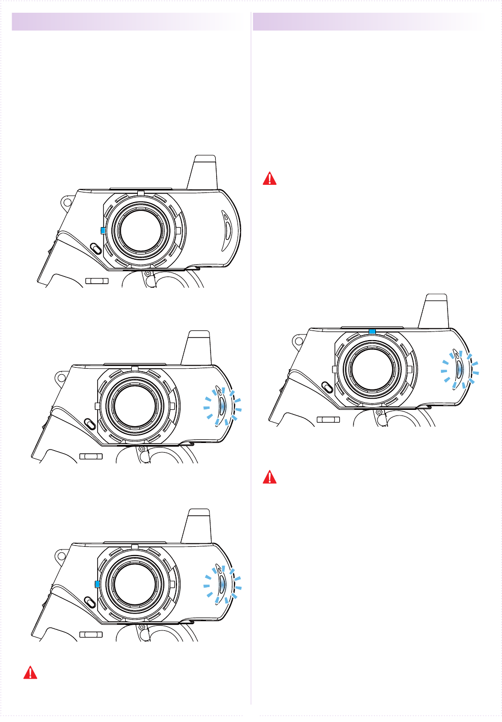
10
● Initializing EX-6 ●
How to change the Modulation mode
1.
2.
3.
Power on while operating ET2 lever below.
ET2
ET2
Power ON
When using the EX-6 for the rst time, please carry
out the following settings.
※ EX-6 will not work normally if the initial
conguration is not set.
※ This is an operation method when the expansion
unit is not assembled.Initialization is necessary
using a dierent method when expansion unit is
put on, see p. 20 for more information.
EX-6 has two Modulation modes.
※ When attaching the Xpansion unit, this operation
is the same.
① Turn o EX-6 switch.
② Push the ET1 lever to the left and power on.
③ Hold ET1 lever until the buzzer sounds and the
LED of EX-6 turns on (approximately two seconds).
《Functions》
● MINI-Z ASF mode : LED Solid
ASF support of MINI-Z series is steerable.
● MINI-Z MHS mode : LED Flashing slowly
Oparating MINI-Z MHS mode. (MR-03 VE PRO)
Hold the ET2 lever until the LED of EX-6 turns
on (approximately two seconds).
After the LED turns on, release ET2 lever.
Buzzer sounds, and reset is completed.
When changing each unit for a different unit, please
perform this initialization again.
Only MINI-Z with ASF/MHS system are operable. FHS
(MINI-Z SPORTS) it will not be able to steer the.
If the pilot LED is blinking fast, this is a warning
that the battery voltage is low. Please change to
new batteries or for a battery pack which has been
charged.
↓
↓
↓
↓
Power ON
↓
↓
↓
ET1
Approximately two seconds,
LED turns on.
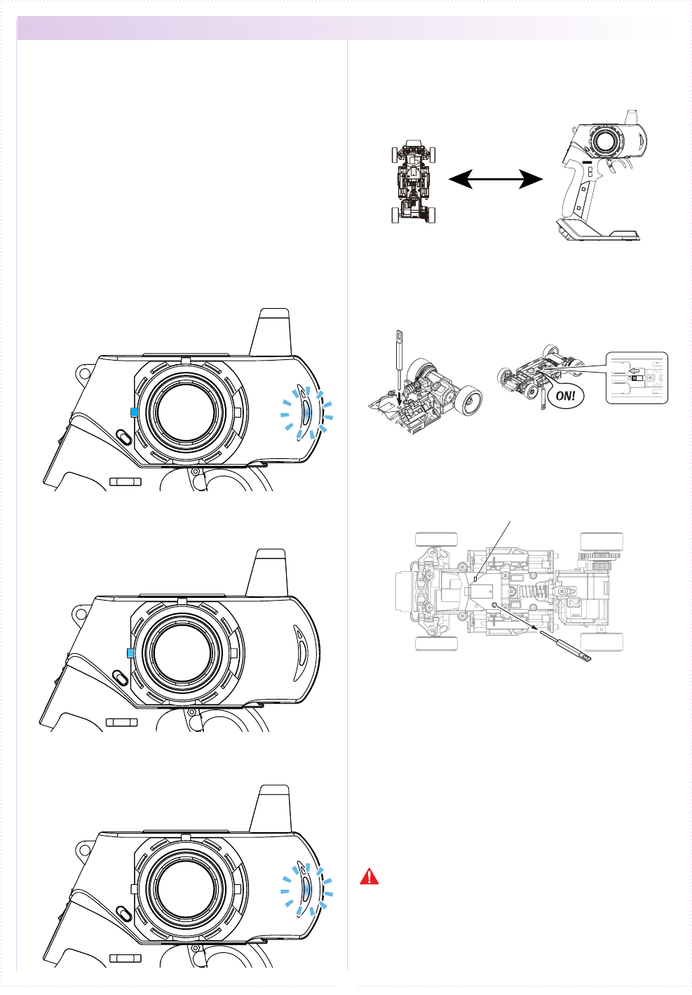
11
① Bring distance of EX-6 and MINI-Z close to about
10cm.
10cm
② Switch on MINI-Z while pushing the pairing button
of MINI-Z.
Pushing pairing button
Switch on
LED
③ After the MINI-Z's LED has lit up, release the
pairing button. Then check that the MINI-Z's LED
lights up again (indicating pairing completion)
① Switch o MINI-Z.
② Switch o the EX-6 main power, then switch on
EX-6 again.
③ Bring distance of EX-6 and MINI-Z close to about
30cm. Switch on the MINI-Z and check that the
receiver LED is lit. If the LED ashes, the MINI-Z
is not getting the EX-6 signal and the pairing
procedure should be repeated.
Preparing the MINI-Z
2.
Preparations for Operation
3.
● Pairing
1.
ET2
ET2
↓
↓
↓
Case without the Xpansion unit
※ Refer to p.21 pairing Operation in the case of
using the Xpansion unit.
In order for the MINI-Z to operate, it must store the
transmitter's unique ID in its memory in a process
called “pairing.” MINI-Z must go through the pairing
process with the transmitter before being used for
the rst time.
※ Please adjust the Modulation mode
before pairing.(p.10) A receiver does
not work normally in dierent mode.
If the mode is changed(General or France), please
conduct pairing procedures with the MINI-Z you are
using again.
Preparing the Transmitter
① While pushing the ET2 lever up, power on.
② When the ET2 lever is released, the LED turns of
EX-6 LED lights up again (indicating transmitter
is transmitting the pairing signal.)
<France mode pairing >
FRANCE mode pairing is possible when the ET2
lever is released after LED turns o. Please use
this feature if the situation is needed.
Power ON
↓
Stand
Trim
Figure 8 Pattern
12
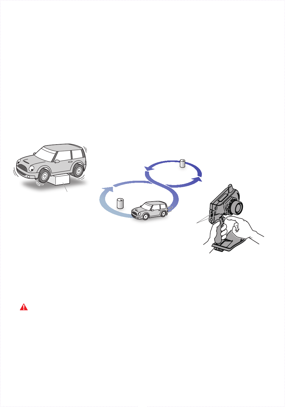
■ Procedures Prior to Operation
1.Switching On
After ensuring that it is safe to do so, switch on the transmitter followed
by the MINI-Z.
2.Model Conrmation
Conrm the model which will be used.
3.Checking Movements
With the model's wheels lifted o the ground, operate transmitter to check
for proper movement. While driving, use steering and throttle trims to make
ne adjustments. Drive in a gure 8 pattern to check steering balance.
4.Switching O
After a driving session, switch o the MINI-Z, followed by the transmitter.
Remove the battery pack from the model.
After switching o, wait at least 5 seconds before switching on again to ensure proper operation.
LeftLeftRight Right
Left
LeftRight
Right
Gap is
zero
Tie Rod
④ Tie rod is
actuated to
just one cup.
13
The sub trim is a convenient feature but it could also complicate the setting process if used incorrectly. Use the sub
trim in the correct manner while also referring to the sub trim operation instructions on p.39 and p.44.
● Trim and Sub Trim Operation
The sub trim is accessed via the
steering menu.
P
Use the sub trim to adjust settings prior to driving instead of the center trim.
P
If the neutral position becomes slightly o during driving, use center trim to correct.
P
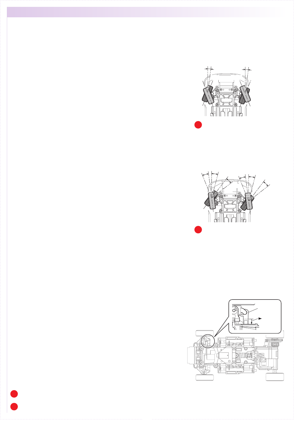
● Trim (Center Trim)
The maximum
steering angle
of the left and
right xed
Adjusting neutral position only.
Initially, steering trim and throttle
trim are assigned to ET1 and ET2
respectively.
P
《Purpose of the Trim》
The trim I have adopted the center trim.
If you have performed an operation to trim as shown on the right,
but the center position (neutral) will move, it does not change the
left and right of the maximum steering angle.
In other words, it does not change the position of the left and
right of the maximum steering angle to make adjustments of the
straight by the trim.
However, we will be going to shift the balance of left and right and
make adjustments by moving the big trim.
《Purpose of the Sub Trim》
When performing the adjustment of the center position by using
the sub trim, minutes you Shifts the center and then moved
together by the same amount the position of the left and right
maximum steering angle.
《Actual Setting Sequence》
① Body throttle is in the neutral state is I make sure to stop
completely. If, please stop the car body by using the throttle
trim if the motor is not stopped.
② Front tire was visually before traveling to adjust by using the
steering sub trim so that the center.
③ It is allowed to actually traveling to check and adjust the
steering of the center. Adjust using the steering sub-trim as the
body runs straight.
④ To quit traveling to check and adjust the steering angle of the
steering by visual observation. When it was operated to full the
handle of the transmitter to the left and right both, as the tie
rod is actuated to just one cup, and then adjusted using the
balance function (P.38).
⑤ Check and adjust the left and right of the turning radius is not
actually running. When it is caused to travel by operating the
steering wheel to the right and left full, by reducing the steering
angle of the turning radius smaller side, to match the radius of
the turning radius is larger side. (Reduce the numerical rotation
radius of the small side in the balance function.)
⑥ Adjust the steering angle of your choice while traveling. The
entire steering angle (adjusted left and right at the same time)
use the steering travel (P.38).
⑦ When the center is shifted to running is corrected by using the
steering trim (center trim).
In conjunction with the center, move
the maximum steering angle of the
left and right together.
● Sub Trim
Neutral
Right
MAX.
Left
MAX.
Neutral
Left LeftRigh
tR
ight
←ET1
Neutral
Left LeftRightRight
→
ニュートラル
ET1
右 最大左 最大
ET1
ET1
14
※ Other than the operation explanation of the
steering wheel,the following function explanation is in
the case of not using the Xpansion unit. Refer to p.38
operation in the case of using the Xpansion unit.
Operate on the left and right, the steering works.
Adjust the left/right steering angles independently.
This enables the turning radius of each side to
match up.
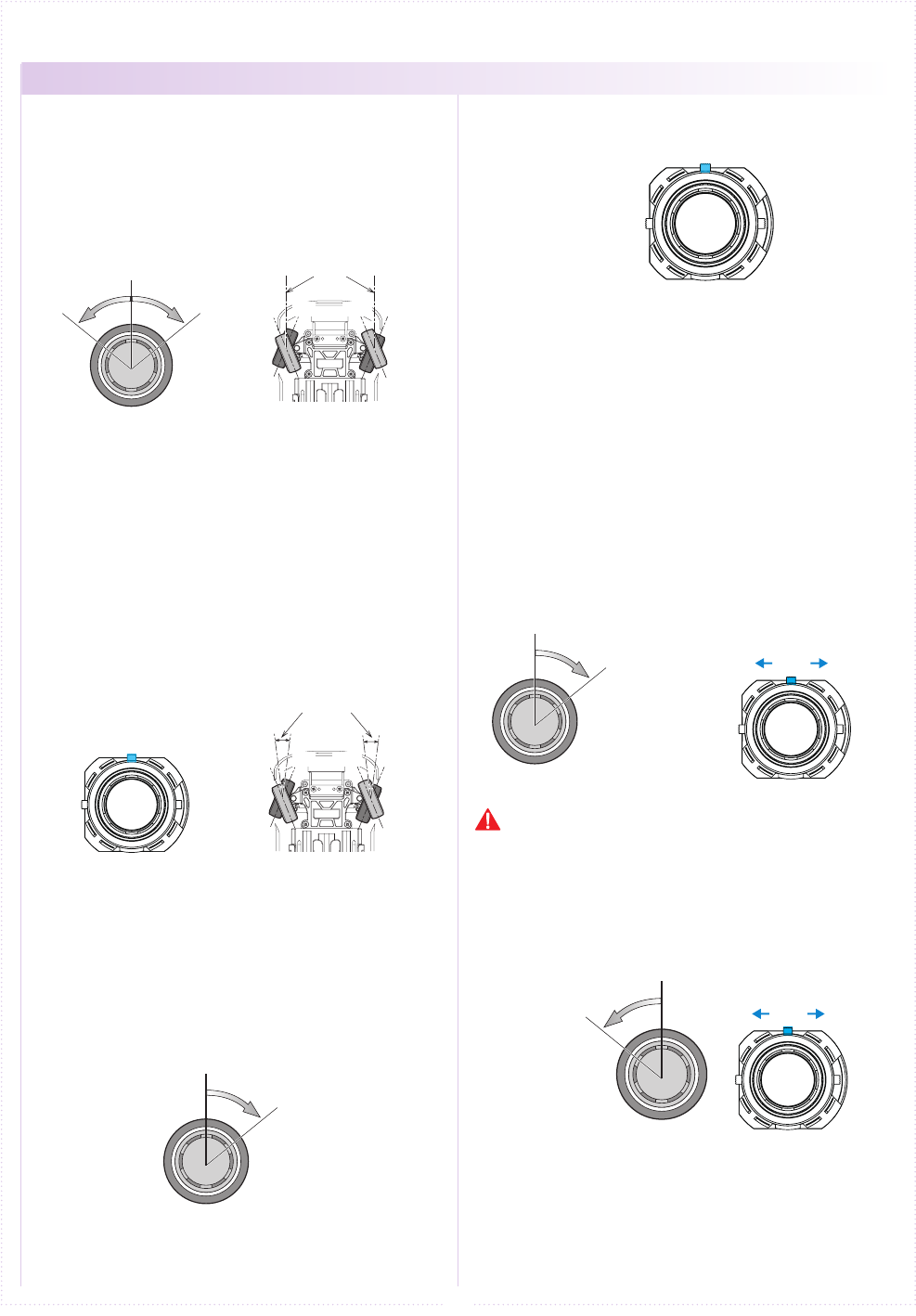
● Travel R
① Hold steering wheel to all the right
② Push ET1 lever by 1 click, adjust the range of
Steering angle.
● Travel L
① Hold steering wheel to all the Left
② Push ET1 lever by 1 click, adjust the range of
Steering angle.
If the direction of the steering is reversed, it will
change the output method.
(when a steering moves to the left while turning
the steering wheel to the right.)
Adjusts the neutral/center position of the steering
angle range. The function to make a ne adjustment
so that a car goes straight, operate the ET1 lever in
the right and left directions.
● A buzzer sound with a single beep sound when
operated to the right and left.
● A buzzer sound "Piro" is made when the trim is at
the center.
● When exceeding the setting range a "Pi-" sound
can be heard.
< ex. Left >
■ Steering wheel
■ Steering travel
■ Steering reverse
■ Steering trim (Center trim)
● STEERING
① Hold the steering wheel all the way to the right .
③ A single buzzer sounds and the steering
directional movement is reversed.
※ Return reverse setting, perform operation ①~③
again.
② Press and hold the ET1 lever to right, wait
about 1 second.
Hold steering wheel
to all the right
Hold steering wheel
to all the right
Do not hold the ET1 lever, or the steering reverse will
be set.
Hold steering wheel
to all the left
■ operating procedure ※ EX-6 can be used even to remove the expansion unit.
Neutral
Neutral
Forward Back
(Brake)
ET2
ET2
ET2
Hold throttle trigger
full brake.
Hold throttle trigger
full brake.
ET2
15
When is the draw in front (hold) operation, it will
forward the vehicle body. When the operation of
pressing, it works to the reverse side (brake).
We will adjust the operation amount of the front
and rear of the throttle, respectively. It uses to
adjustment and brake adjustment of the maximum
speed.
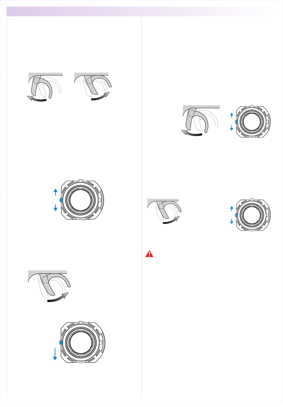
● Travel F(Forward)
① Hold throttle trigger full throttle.
② Push ET2 lever by 1 click, adjust the range of
throttle movment angle. Quantity of the movement
increases and decreases when operating the ET2
lever up or down respectively.
● Travel B(Brake)
① Hold throttle trigger full brake.
② Push ET2 lever by 1 click, adjust the range of
throttle movment angle. Quantity of the movement
increases and decreases when operating the ET2
lever up or down respectively.
Adjusts the neutral/center position of the throttle
stroke range.The function to make a ne adjustment,
operate ET2 lever in up and down.
● A buzzer sound with a single beep sound when
operated up or down.
● A buzzer sound "Piro" is made when the trim is at
the center.
● When exceeding the setting range a "Pi-" sound
can be heard.
If the forward and the reverse of the direction is
reversed, it will change the output method.
(when the brake is moving the forward throttle.)
① Hold throttle trigger full brake.
③ A single buzzer sounds and the throttle directional
movement is reversed.
※ Return reverse setting, perform operation ①~③
again.
② Press and hold the ET2 lever down, wait about
1 second.
Forward
Increase
Increase
Decrease
Decrease
Back
■ Throttle trigger
■ Throttle travel
■ Throttle trim
■ Throttle reverse
● THROTTLE
Hold full throttle
Do not hold the ET2 lever, or the steering reverse will
be set.
※ Other than the operation explanation of the trigger
movement, the following function explanation in case
of not using the Xpansion unit. Refer to p.43 operation
in the case of using the Xpansion unit.

ET3
BT1
16
Operating the ET3 lever, controls the 3ch
servo.
※ The funtion explaination is in the case when not
using the Xpansion unit. Refer to p.28 operation
in the case of assembled Xpansion unit.
When the button of BT1 is operated, it is
possible to operate the signal of 4CH.
※ The funtion explaination is in the case when not
using the Xpansion unit. Refer to p.28 operation
in the case of assembled Xpansion unit.
① Use it for steering gyro gain (eect) control of
MINI-Z MR-03VE PRO for MHS.
Example
● 3CH operation ● 4CH operation
ST TURN 50
%
ST RETURN 100
%
ターンスピード
リターンスピード
ST SPEED スピード
ST TURN 100
%
ST RETURN 100
%
ターンスピード
リターンスピード
ST SPEED スピード
ST TURN 50
%
ST RETURN 100
%
ターンスピード
リターンスピード
ST SPEED スピード
ST TURN 100
%
ST RETURN 100
%
ターンスピード
リターンスピード
ST SPEED スピード
17
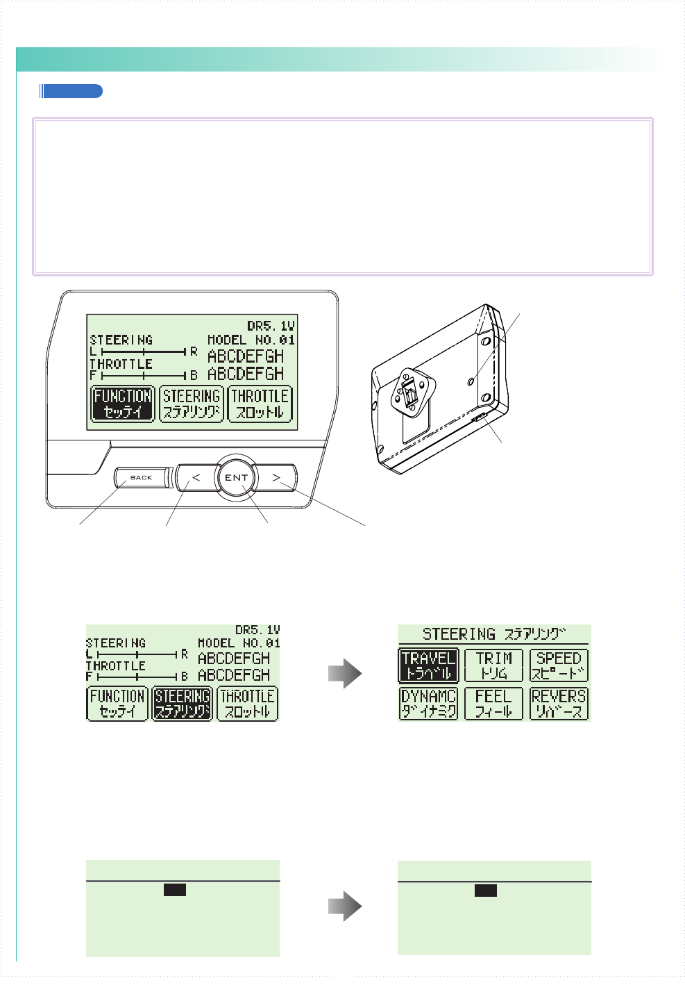
【 Basic Operation 1: Selecting from a Menu 】
This explanation uses [Steering] as an example.
① Use the R(>) key to move the cursor over [Steering].
② Press the ENTER key to change to the Steering Menu screen.
【 Basic Operation 2: Changing a Setting Value 】
This explanation uses [TURN 1] on the Steering Speed screen as an example.
① Use R(>) key to move the cursor over the 100% value next to [ST TURN].
② Press ENTER key to select it for modication.
③ Once selected, the cursor will blink. Now use the L(<)key+R(>)key to change the value.
④ After changing the value, press the ENTER key again to conrm the change.
■
Display and Control Method with the Xpansion unit attached
● Basic Operations to Change Settings
BACK Key L( < )Key R( > )Key
Command Button
Communication port
Used for rmware upgrading.
Used for rmware upgrading
and ICS communication.
ENT Key
Controlling of the setting adjustments is done via the L(<) key, R(>)key,
ENTER(ENT) key, and BACK key.
Operation
ENT Key: Selecting item to be modied; Conrming a change after a setting change.
L( < )Key: Used to move cursor between menu choices and to change a setting value.
Lowering a value (for L/R cases: raising toward L); Return to a previous menu item.
R( > )Key: Used to move cursor between menu choices and to change a setting value.
Raising value (for L/R cases: raising toward R); Proceed to next menu item.
BACK Key:Returning to previous screen; Canceling change
L(<) key + R(>) key Pressing simultaneously: Resets the value to default setting.
A
B
18
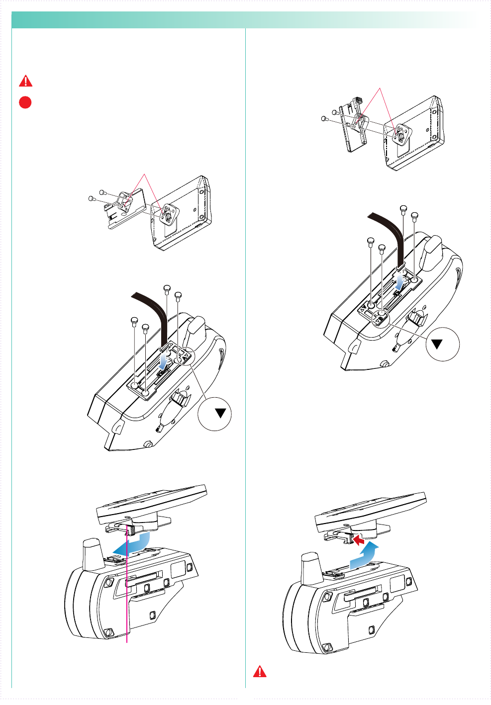
② Attach the monitor bracket to the master
unit. ※[A▼]mark to the steering side
② Attach the monitor bracket to the master
unit. ※ Apply [B ▼] mark to the steering side
① Attach the monitor base parallel to
Xpansion unit. ※ Factory setting.
※ The disconnecting method is the same for side
and front positions.
① Attach the monitor base at a right angle to
Xpansion Unit. ※ Dierent Factory setting.
Attention to the marker.
Attention to the marker.
M2.6-6BH
M2.6-6BH
x 2
x 2
x 4
x 4
TP2.6-8BH
Self tapping screws
TP2.6-8BH
Self tapping screws
Connect the wire of the
Xpansion unit to the
master unit.
Connect the wire of the
Xpansion unit to the
master unit.
③ Attach expansion unit to the master unit.
③ Attach the Xpansion unit to the master unit.
※ Attach the monitor base and bracket as
shown in gure A ③ .
1.While pushing the monitor-based apart.
2.Slide the Xpansion like shown in the gure
below and take o.
While matching the edge of the base with
the dent of the bracket, slide it until the
Xpansion unit locks.
A ▼:setting to the front
Xpansion unit can be mounted facing the
front or the side. The factory setting is
mounted to the front.
▼ B:when mounting sideways
How to disconnect the Xpansion unit.
When connecting or disconnecting the Xpansion unit to
EX-6, please switch o the EX-6.
Be careful to not misuse the M2.6-6BH and TP2.6-
8BH screws.
Xpansioun unit can be mounted in two different
directions using the monitor base and bracket.
P
● Installation of expansion unit
1 2
※
Depending on the model, expansion unit has been installed at the factory.