LG Electronics USA 71PY1MWA Plasma Monitor User Manual 38289U0558C
LG Electronics USA Plasma Monitor 38289U0558C
Contents
- 1. User manual 1
- 2. User manual 2
- 3. User manual 3
User manual 2
8 Plasma Monitor
Introduction
Controls
Controls
INPUT
MENU
VOL
TruSurround XT
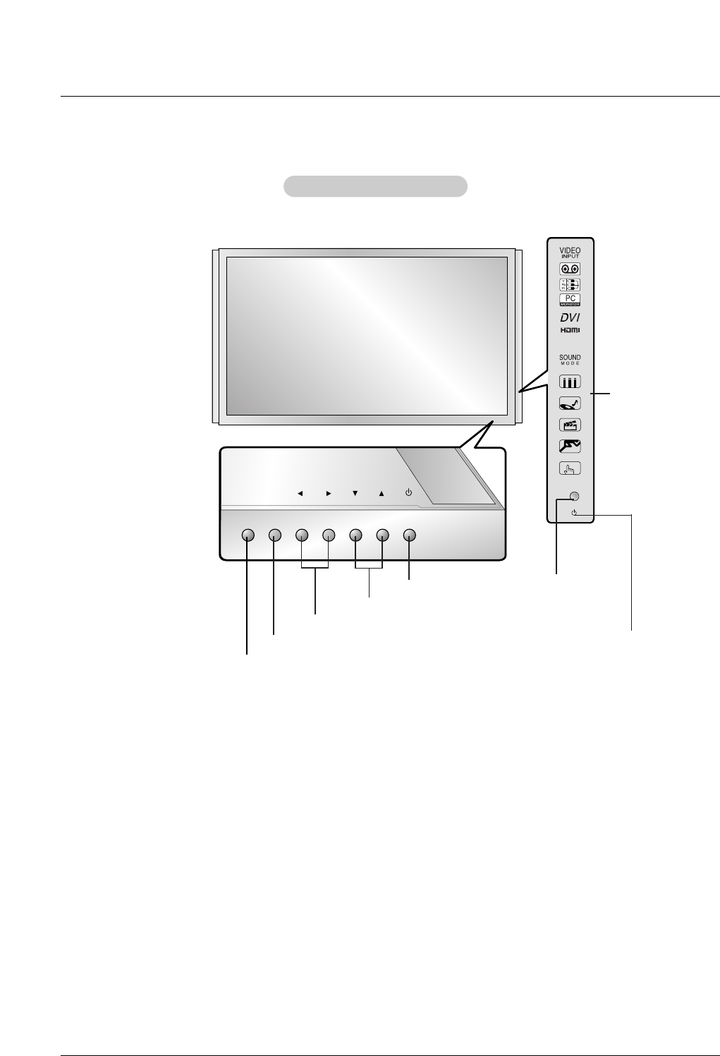
Front Panel Controls
Front Panel Controls
MENU Button
INPUT Button
VOLUME (FF,GG) Buttons
EE, DDButtons
INDEX
Switches
LED Display
on or off.
Remote
Control
Sensor
Power Indicator
Illuminates red in standby
mode, Illuminates green when
the monitor is turned on.
Sub power Button
Owner’s Manual 9
Introduction
Connection Options
Connection Options
DIGITAL AUDIO
OUT
OPTICAL
HDMI/DVI IN HDMI/DVI IN
1
2
RS-232C INRS-232C IN
(CONTROL & SERVICE)
VIDEOVIDEO
AUDIO
COMPONENTCOMPONENT IN IN
VIDEOVIDEO
AUDIOAUDIO
MONO
( )
S-VIDEOS-VIDEO
VIDEO IN
VIDEO IN 3VIDEO IN 3 VIDEO IN 4VIDEO IN 4
AUDIO (RGB/DVI)AUDIO (RGB/DVI)
RGB INRGB IN
RGB(PC/DTV)RGB(PC/DTV)
REMOTE REMOTE
CONTROL INCONTROL IN
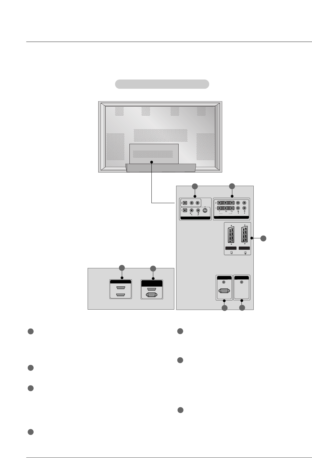
Back Connection Panel
Back Connection Panel
1
6
2
5
7
34
HDMI/DVI IN
Connect a HDMI signal to 1 or 2.
Or DVI (VIDEO)signal to the 1 port with a DVI to HDMI
cable.
RS-232C IN (CONTROL & SERVICE) PORT
Connect to the RS-232C port on a PC.
VIDEO IN
Connect audio/video output from an external device to
these jacks.
S-VIDEO
Connect S-Video out from an S-VIDEO device.
COMPONENT IN
Connect a component video/audio device to these jacks.
EURO SCART SOCKET
Connect the euro scart of the VCR to these sockets.
RGB IN
AUDIO (RGB/DVI)
Connect the monitor output from a PC to the appropriate
input port.
RGB(PC/DTV)
Connect the monitor output from a PC to the appropriate
input port.
Remote Control Port
Connect your wired remote control.
1
7
2
3
4
5
6
10 Plasma Monitor
Introduction
- When using the remote control, aim it at the remote control sensor on the monitor.
- Under certain conditions such as if the remote IR signal is interrupted, the remote control may not function. Press
the key again as necessary.
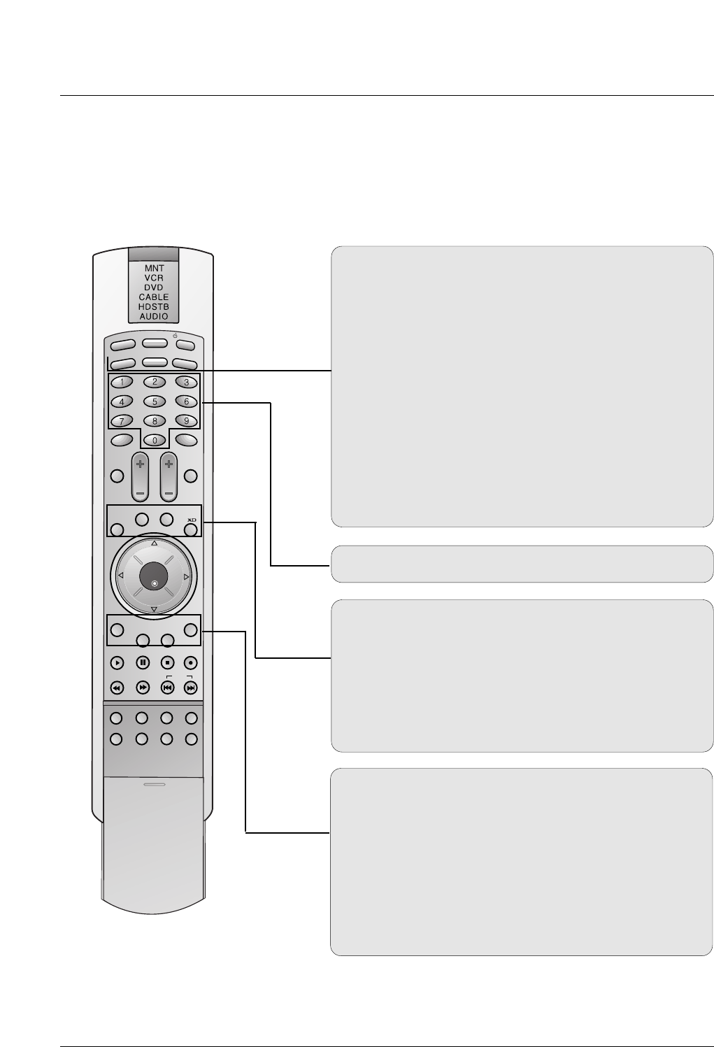
Remote Control Key Functions
Remote Control Key Functions
LIGHT
INPUT
MODE
PIP
MUTE SLEEP
VOL CH
WIN. SIZE
WIN. POSITION
SWAP
MENU
PIP INPUT ARC
EXIT
PLAY PAUSE STOP RECORD
VIDEO COM1 RGB
HDMI1
ENTER
HDMI2
KEY LOCK INDEX
REW FF SKIP
POWER
DW
DASP
APC
COM2
LIGHT
Illuminates the remote control buttons.
MODE
Selects the remote operating mode: MNT, VCR, DVD,
CABLE, HDSTB or AUDIO.
INPUT
Selects: Video1-2-3-4, Component 1-2, RGB-DTV (or RGB-
PC),
DVI-DTV (or DVI-PC), HDMI input sources.
POWER
Turns your monitor or any other programmed equipment on or
off, depending on mode.
PIP
Selects the PIP mode.
DW
Selects the DW mode.
WIN. SIZE
Adjusts the sub picture size.
NUMBER buttons
Dosen’t work for monitor mode.
WIN.POSITION
Moves the sub picture.
SWAP
Exchanges the main/sub images.
XD
Switches the XD on or off.
(Refer to p. 19)
MENU
Brings up the main menu to the screen.
PIP INPUT
Selects the input source for the sub picture.
ARC
Changes the picture format. (Refer to p. 25)
EXIT
Clears all on-screen displays and returns to monitor viewing
from any menu.
Owner’s Manual 11
Installing Batteries
• Open the battery compartment cover on the back side and install the batteries
matching correct polarity (+ with +, - with -).
• Install two 1.5V AA batteries. Don’t mix old or used batteries with new ones.
Replace cover.
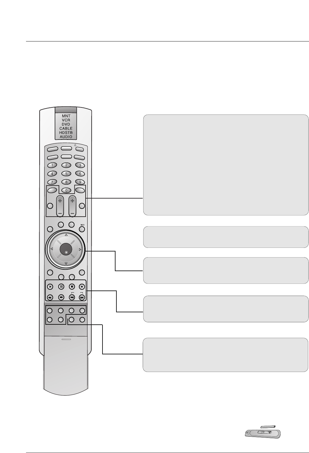
THUMBSTICK (Up/Down/Left/Right/ENTER)
Navigate the on-screen menus and adjust the system settings
to your preference.
KEY LOCK
Switches the key lock on or off.
INDEX
Switches LED Display on or off.
DASP
To select the sound appropriate to your viewing program
character:
SRS TSXT, Flat, Music, Cinema, Sports, or User
(Refer to p.21)
MUTE
Switches the sound on or off.
SLEEP
Sets the Sleep Timer.
VOLUME UP/DOWN
Increases/decreases the sound level.
CHANNEL UP/DOWN
Selects available channels.
Dosen’t work for monitor mode.
LIGHT
INPUT
MODE
PIP
MUTE SLEEP
VOL CH
WIN. SIZE
WIN. POSITION
SWAP
MENU
PIP INPUT ARC
EXIT
PLAY PAUSE STOP RECORD
VIDEO COM1 RGB
HDMI1
ENTER
HDMI2
KEY LOCK INDEX
REW FF SKIP
POWER
DW
DASP
APC
COM2
VIDEO/COM1/COM2/RGB/HDMI1/HDMI2
Selects: Video1-2-3-4, Component 1-2, RGB-DTV (or RGB-
PC),HDMI1, HDMI2 input sources.
VCR/DVD/DVHS/Camcorder BUTTONS
Control some video cassette recorders or DVD players
("RECORD" button is not available for DVD player).
12 Plasma Monitor
Installation
4 inches
4 inches
4 inches4 inches
2 inches
W
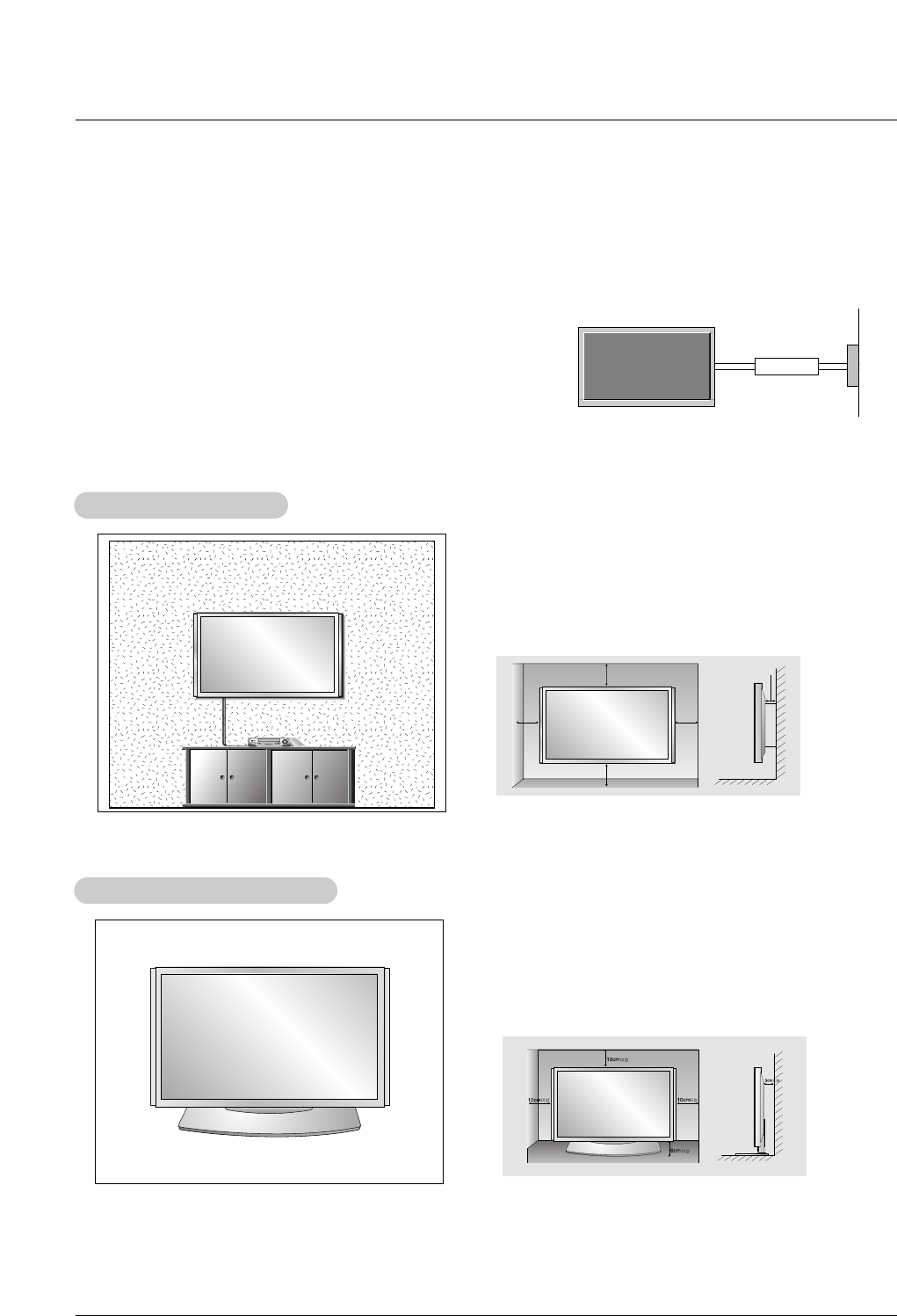
Wall Mount Installation
all Mount Installation
For proper ventilation, allow a clearance of 4” on each
side and 2” from the wall. Detailed installation instruc-
tions are available from your dealer, see the optional
Wall Mounting Bracket Installation and Setup Guide.
Installation Instructions
Installation Instructions
•Install this monitor only in a location where adequate ventilation is available.
GROUNDING
Ensure that you connect the grounding / earth wire to prevent possible
electric shock. If grounding methods are not possible, have a qualified
electrician install a separate circuit breaker. Do not try to ground the
unit by connecting it to telephone wires, lightening rods, or gas pipes.
Power
Supply
Short-circuit
Breaker
Desktop Pedestal Installation
Desktop Pedestal Installation
For proper ventilation, allow a clearance of 4” on each
side and the top, 2.36” on the bottom, and 2” from the
wall. Detailed installation instructions are included in the
optional Desktop Stand Installation and Setup Guide
available from your dealer.
Owner’s Manual 13
Installation
External Equipment Connections
External Equipment Connections
NOTE: Not all cables shown are included with the plasma display.
- To avoid picture noise (interference), leave an adequate distance between the VCR and Monitor.
- Use the ISM Method feature to avoid having a fixed image remain on the screen for a long period of time. Typically a frozen still
picture from a VCR. If the 4:3 picture format is used; the fixed image may remain visible on the screen.
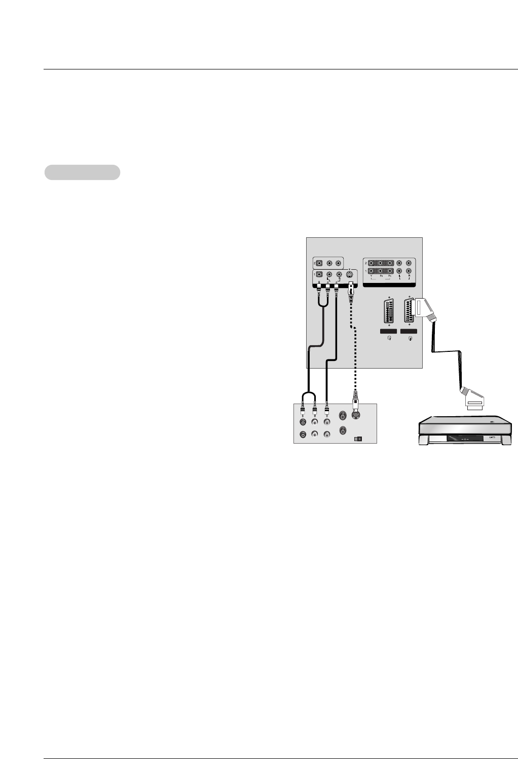
How to connect
1. Connect the audio and video cables from the VCR's output
jacks to the monitor input jacks, as shown in the figure.
When connecting the monitor to VCR, match the jack colors
(Video = yellow, Audio Left = white, and Audio Right = red).
2. If you connect an S-VIDEO output from VCR to the S-
VIDEO input, the picture quality is improved; compared to
connecting a regular VCR to the Video input.
3. If you connect the Euro scart socket of the VCR to the Euro
scart socket of the set. No other connection is needed.
Mono VCR: Connect the video output cable from the VCR
to the VIDEO input on the monitor.
S-VIDEO VCR: Connect the S-Video output cable from the
VCR to the S-VIDEO input on the monitor. (Note that S-
Video offers higher quality).
How to use
1. Insert a video tape into the VCR and press PLAY on the
VCR.
(Refer to the VCR owner’s manual.)
2. Use the INPUT button on the remote control to select
Video 1 or Video 3.
VCR Setup
VCR Setup
VIDEO
AUDIO
COMPONENT IN
VIDEO
AUDIO
MONO
( )
S-VIDEO
VIDEO INVIDEO IN
VIDEO IN 3 VIDEO IN 4
S-VIDEO OUT
IN
(R) AUDIO (L) VIDEO
34
OUTPUT
SWITCH
ANT OUT
ANT IN
VCR
or
14 Plasma Monitor
Installation
External Equipment Connections
External Equipment Connections
- After subscribing to a cable monitor service from a local provider and installing a converter, you can watch cable TV program-
ming. The monitor cannot display monitor programming unless a TV tuner device or cable TV converter box is connected to the
Monitor.
- For further information regarding cable monitor service, contact your local cable TV service provider(s).
How to connect
1. Connect the audio and video cables from the Cable Box's output
jacks to the monitor input jacks, as shown in the figure.
When connecting the monitor to a Cable Box, match the jack colors
(Video = yellow, Audio Left = white, and Audio Right = red).
Or, connect the Euro scart socket of the Cable box to the Euro scart
socket of the set.
How to use
1. Use the INPUT button on the remote control to select Video 1.
(If connected to VIDEO 2, VIDEO 3 or VIDEO 4, select the Video 2,
Video 3 or Video 4 input source.)
2. Select your desired channel with the remote control for cable box.
Cable
Cable TV Setup
TV Setup
VIDEOVIDEO
AUDIOAUDIO
COMPONENTCOMPONENT IN IN
VIDEOVIDEO
AUDIOAUDIO
MONO
( )
S-VIDEOS-VIDEO
VIDEO IN
TV
VCR RF Cable
(R) AUDIO (L)
VIDEO
Cable Box
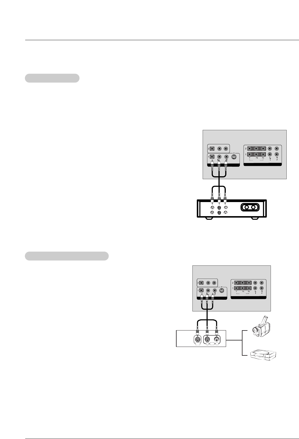
How to connect
1. Connect the audio and video cables from the external
equipment's output jacks to the monitor input jacks, as
shown in the figure.
When connecting the monitor to external equipment, match
the jack colors (Video = yellow, Audio Left = white, and
Audio Right = red).
Or, connect the Euro scart socket of the External A/V to the
Euro scart socket of the set.
How to use
1. Use the INPUT button on the remote control to select
Video1.(If connected to VIDEO 2, VIDEO 3 or VIDEO 4,
select the Video 2, Video 3 or Video 4 input source.)
2. Operate the corresponding external equipment. Refer to
external equipment operating guide.
External
External A/V Source Setup
A/V Source Setup
VIDEOVIDEO
AUDIOAUDIO
COMPONENTCOMPONENT IN IN
VIDEOVIDEO
AUDIOAUDIO
MONO
( )
S-VIDEOS-VIDEO
VIDEO INVIDEO IN
RL
AUDIO
VIDEO
Video Game Set
Camcorder
Owner’s Manual 15
Installation
•Component Input ports
To get better picture quality, connect a DVD
player to the component input ports as shown.
How to connect
1. Use the monitor’s COMPONENT (Y, PB, PR) INPUT, RGB, DVI or HDMI jack for video connections, depending
on your set-top box connector. Then, make the corresponding audio connections.
How to use
1. Turn on the digital set-top box. (Refer to the owner’s manual for the digital set-top box.)
2. Use INPUT on the remote control to select Component 1, Component 2, RGB, DVI or HDMI.
DTV Setup
DTV Setup
Component ports of the
Monitor YPBPR
Video output ports
of DVD player
Y
Y
Y
Y
Pb
B-Y
Cb
PB
Pr
R-Y
Cr
PR
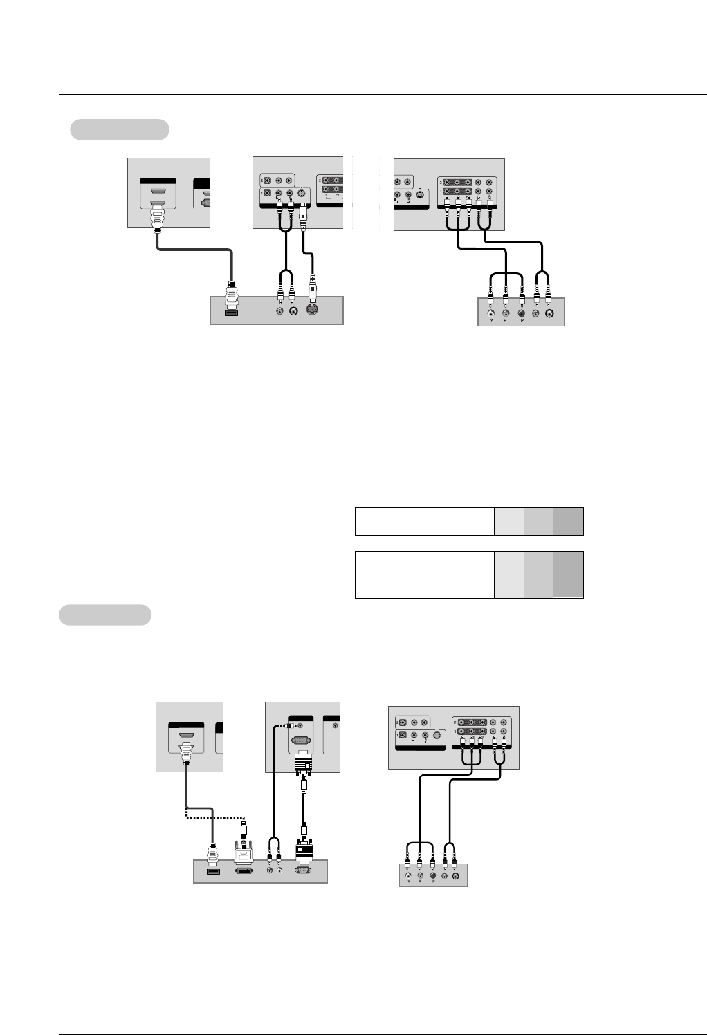
How to connect
1. Connect the DVD video outputs to the COMPONENT (Y, PB, PR) or HDMI INPUT jacks and connect the DVD
audio outputs to the AUDIO INPUT jacks on the monitor, as shown in the figure.
2. If your DVD only has an S-Video output jack, connect this to the S-VIDEO input on the monitor and connect the
DVD audio outputs to the AUDIO INPUT jacks on the monitor, as shown in the figure.
How to use
1. Turn on the DVD player, insert a DVD.
2. Use the INPUT button on the remote control to select Component 1, Component 2, HDMI1 or 2. (If connect-
ed to S-VIDEO, select the Video 1 external input source.)
3. Refer to the DVD player's manual for operating instructions.
DVD Setup
DVD Setup
AUDIO (RGB/DVI)AUDIO (RGB/DVI)
RGB INRGB IN
RGB(PC/DTV)RGB(PC/DTV)
REMOTE REMOTE
CONTROL INCONTROL IN
RGB-DTV OUTPUT
(R) AUDIO (L)
HDMI OUTPUT
VIDEOVIDEO
AUDIO
COMPONENTCOMPONENT IN
VIDEOVIDEO
AUDIOAUDIO
MONO
( )
S-VIDEOS-VIDEO
VIDEO IN
BR
(R) AUDIO (L)
HDMI/DVI IN HDMI/DVI IN
1
2
RS-232C INRS-232C IN
(CONTROL & SERVICE)
DVI-DTV OUTPUT
DVD
Digital Set-top Box
or
or
HDMI/DVI IN
1
2
RS-232C INRS-232C IN
(CONTROL(CONTROL & SER & SERVICE)VICE)
VIDEOVIDEO
AUDIO
COMPONENT IN
VIDEOVIDEO
AUDIOAUDIO
MONO
( )
S-VIDEOS-VIDEO
VIDEO INVIDEO IN
HDMI OUTPUT
VIDEO
AUDIO
COMPONENT IN
VIDEO
AUDIO
( )
S-VIDEO
VIDEO IN
(R) AUDIO (L)
S-VIDEO
HDMI/DVI IN
1
2
RS-232C IN
(CONTROL & SERVICE)
VIDEO
AUDIO
COMPONENT IN
VIDEO
AUDIO
( )
S-VIDEO
VIDEO IN
VIDEOVIDEO
AUDIOAUDIO
COMPONENT IN
BR
(R) AUDIO (L)
VIDEOVIDEO
AUDIOAUDIO
MONO
( )
S-VIDEOS-VIDEO
VIDEO INVIDEO IN
- To watch digitally broadcast programs, purchase and connect a digital set-top box.
- This monitor supports HDCP (High-bandwidth Digital Contents Protection) protocol for
DVI DTV (480p,720p,1080i) mode.