LG Electronics USA DT-CK PERSONAL COMPUTER User Manual CKDK
LG Electronics USA PERSONAL COMPUTER CKDK
UserManual.wiki
>
LG Electronics USA
>
DT-CK User Manual
>
USERS MANUAL 4 OF 4
Contents
1.
USER MANUAL 1 OF 4
2.
USER MANUAL 2 OF 4
3.
USER MANUAL 3 OF 4
4.
USERS MANUAL 4 OF 4
USERS MANUAL 4 OF 4
Navigation menu
Upload a User Manual
Namespaces
Wiki Guide
HTML
PDF
Info
Views
User Manual
Discussion / Help
Navigation
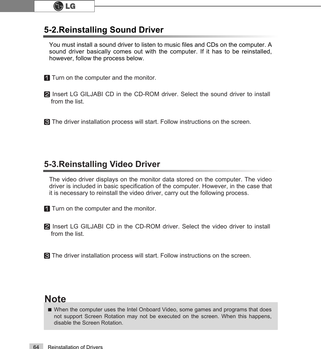

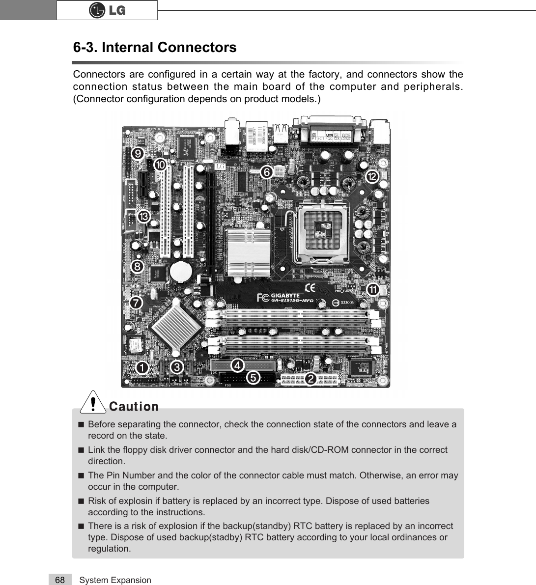
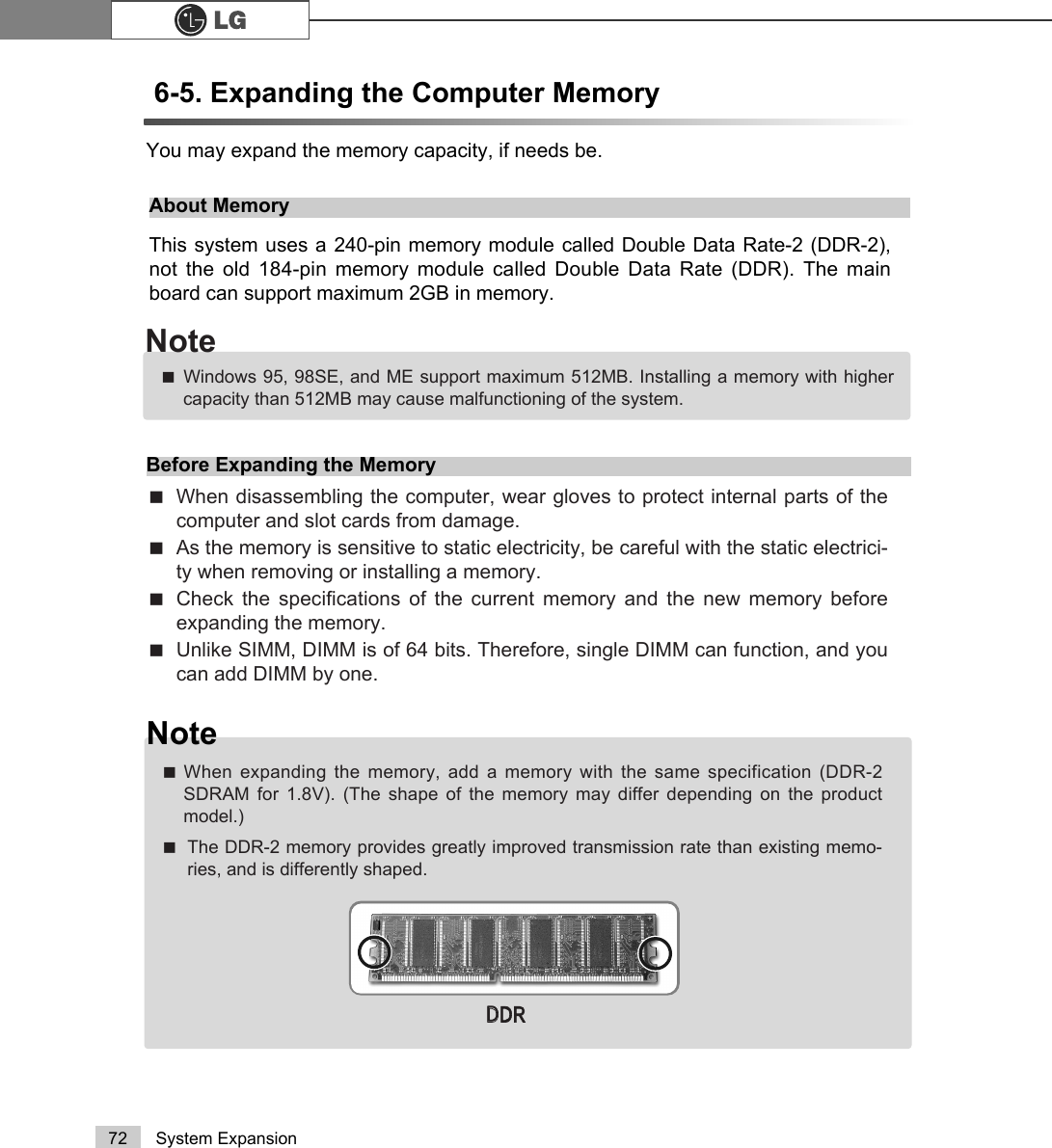
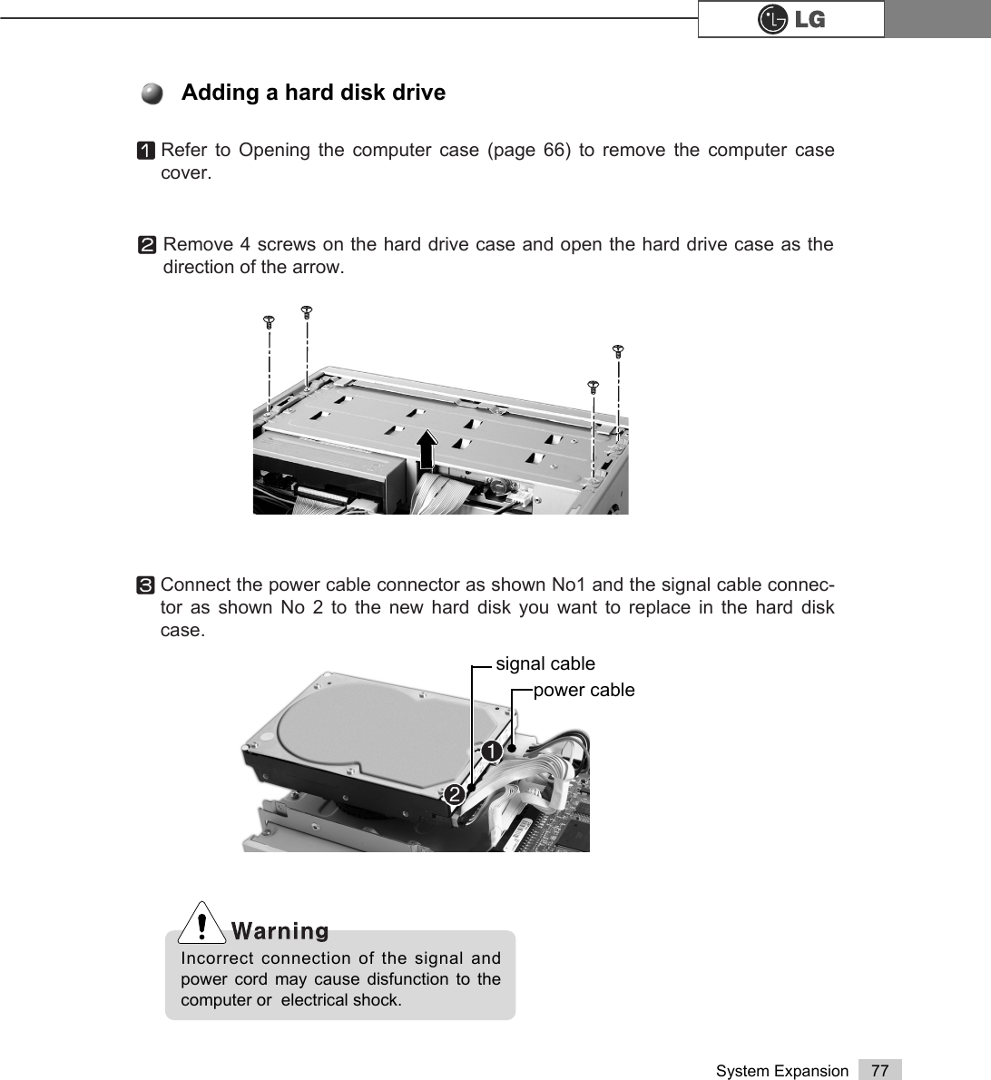
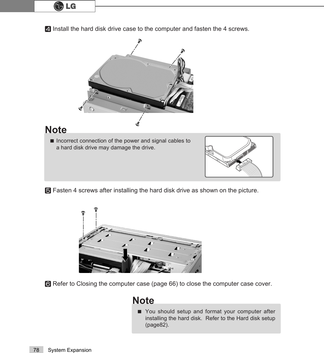
![75System ExpansionChecking the Expanded MemoryTurn on the power after installing the memory. Then, the computer will detect the mem-ory so that you don't need to change the system setup. The capacity of the installedmemory is checked as follows.ⓞConnect the power cord and other cables, and turn on the computer and the moni-tor. Then, the initial screen to check the status of the computer will appear.ⓟWhen the following screen appears, press [Esc] key. Then, POST screen willappear.ⓠOn the next screen, press [Pause] to freeze the screen temporarily and to checkthe Memory Testing : XXXXXX OK part.ⓡAfter checking the memory, press the [Esc] key. Windows screen will proceed.ãIn the case that the logo screen is processed too fast to stop, press [Delete] key on theLG logo screen. Then, select Advanced BIOS Features ĚFull Screen Logo ShowSelectable, and change status from Enabled to Disabled.Note$ZDUG0RGXODU%,26Y;;;;;$Q(QHUJ\6WDU$OO\&RS\ULJKW&$ZDUG6RIWZDUH,QF%XLOG,'/*;;;;;;;;;;;;;;0DLQ3URFHVVRU,QWHO53HQWLXP5;3URFHVVRU;;;0+]0HPRU\7HVW;;;;;;2.3UHVV'(/WRHQWHU6(783;;;;;;;;;;;;;;;;;;;;;;;;;0HPRU\7HVWLQJ;;;;;;2.](https://usermanual.wiki/LG-Electronics-USA/DT-CK.USERS-MANUAL-4-OF-4/User-Guide-570605-Page-12.png)
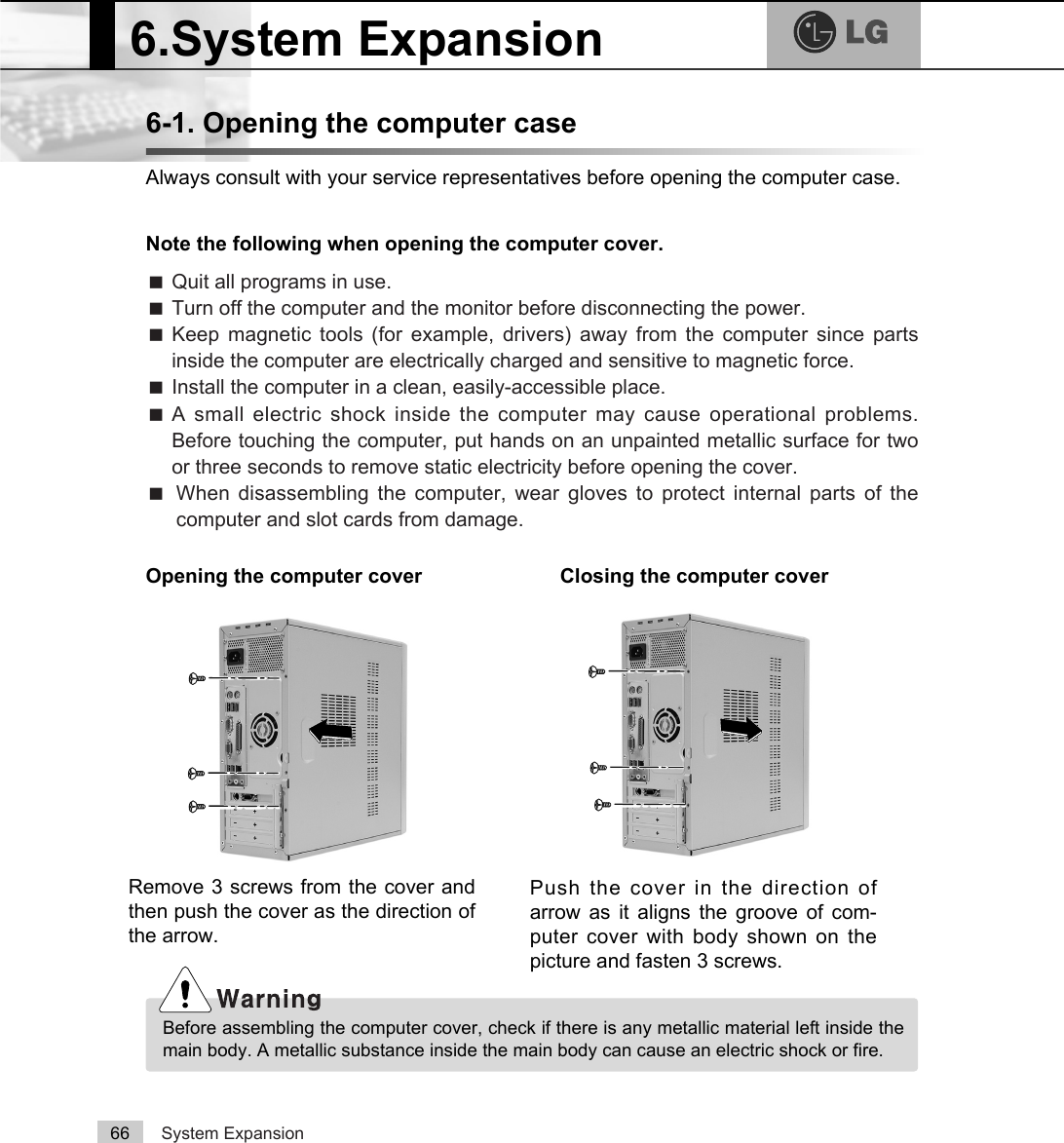
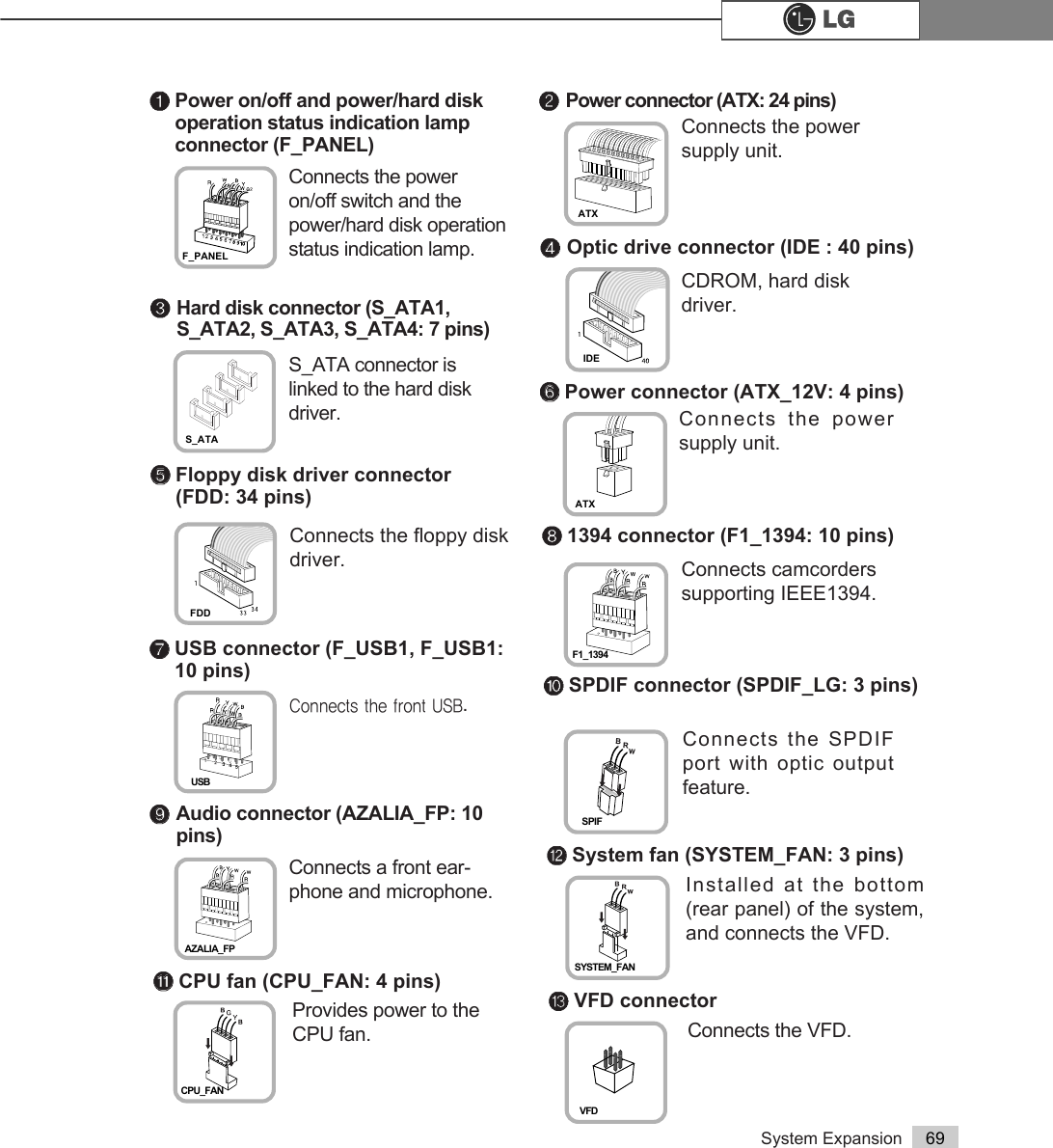
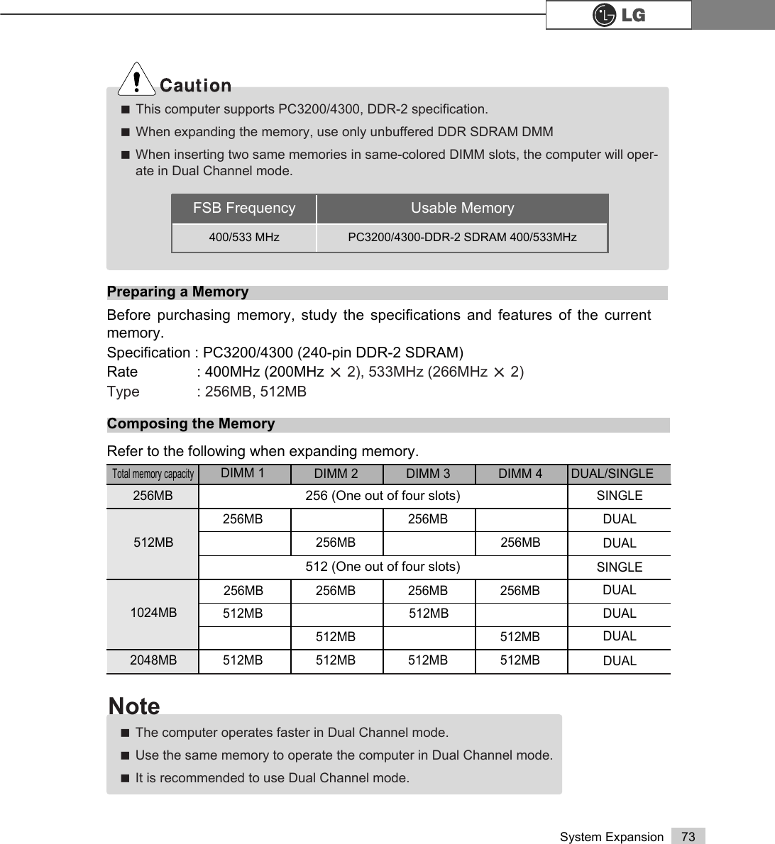
![79System ExpansionⓞTurn on the computer and the monitor.ⓟWhile the LG logo screen is on, press [Delete] key.ⓠThen, the initial screen of System Setup menu will appear. ⓡExecute the initial screen of the System Setup menu, and select StandardCMOS Features by pressing >Ⓑ@>Ⓒ@>⒵@, and >Ⓐ@keys. Then, press [Enter].Hard disk drive setup3KRHQL[$ZDUG%,26&0266HWXS8WLOLW\Ě 6WDQGDUG&026)HDWXUHV Ě3&+HDOWK6WDWXVĚ $GYDQFHG%,26)HDWXUHV Ě )UHTXHQF\9ROWDJH&RQWUROĚ $GYDQFHG&KLSVHW)HDWXUHV /RDG2SWLPL]HG'HIDXOWVĚ ,QWHJUDWHG3HULSKHUDOV 6HW3DVVZRUGĚ 3RZHU0DQDJHPHQW6HWXS 6DYH([LW6HWXSĚ 3Q33&,&RQILJXUDWLRQV ([LW:LWKRXW6DYLQJ(VF4XLW êëè é 6HOHFWOWHP)6DYH([LW6HWXS9LUXV3URWHFWLRQ%RRW6HTXHQFH](https://usermanual.wiki/LG-Electronics-USA/DT-CK.USERS-MANUAL-4-OF-4/User-Guide-570605-Page-16.png)
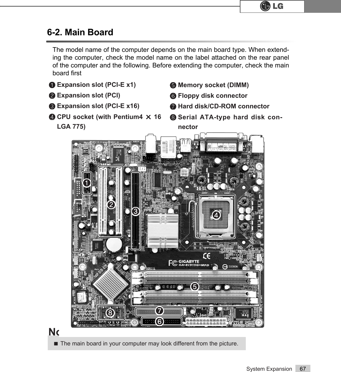
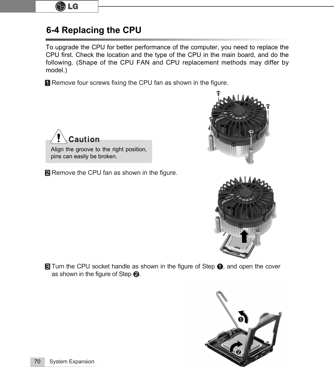
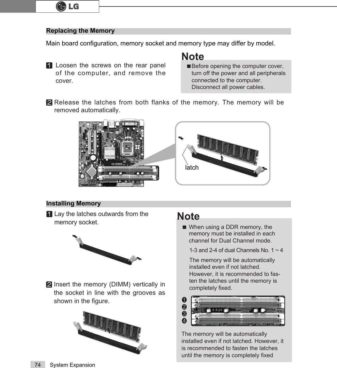
![80 System ExpansionⓢWhen the following appears, select IDE Channel 0 Salve by pressing>Ⓑ@>Ⓒ@>⒵@, and >Ⓐ@keys and press [Enter] key.ⓣPress [Enter] key on IDE Channel 0 Slave to set it as Auto, and press [Enter]key again on IDE HDD Auto-Detection to set it as Slave. Then, the additionallyinstalled hard disk will be automatically detected.ⓤTo save changes in System Setup, press the [F10] key.ⓥWhen the following message appears, press the [Enter] key to restart the computer.Phoenix-Award BIOS CMOS Set up UtilityStandard BIOS FeaturesData (mm:dd:yy) XXX, XXX, XXXXTime (hh:mm:ss) XX, XX, XXĚIDE Channel 0 Master Press EnterXXXXXMBĚIDE Channel 0 Slave Press Enter None ĚIDE Channel 1 Master Press Enter None ĚIDE Channel 1 Slave Press Enter None Drive A X.XXM, X.XinDrive B NoneVideo EGA/VGAHalt On All, But Keyboard.CPU Type X.XXX.XXX.XXBIOS Version Build ID :LG Video Memory X.XX KSystem Memory X.XX KTotal Memory X.XX KItem HelpMenu Level ĚTo auto-detect theHDD's size, head...onthis channelêëèé:Move Enter:Select +/-/PU/PD:Value F10:Save ESC:Exit F1:General HelpF5:Previous Values F7:Optimized Defaults3UHVV(QWHU1RQHĚ,'(&KDQQHO6ODYHIDE HDD Auto-DetectionPress EnterIDE Channel 0 Slave AutoAccess Mode AutoCapacity 0 MB Cylinder 0Head 0Precomp 0Lauding Zome 0Sector 0 Item HelpMenu Level ĚTo auto-detect theHDD's size, head...onthis channelêëèé:Move Enter:Select +/-/PU/PD:Value F10:Save ESC:Exit F1:General HelpF5:Previous Values F7:Optimized Defaults$XWR3UHVV(QWHU6$9(WR&026 DQG(;,7<1"<Phoenix-Award BIOS CMOS Set up UtilityIDE Channel 0 Slave](https://usermanual.wiki/LG-Electronics-USA/DT-CK.USERS-MANUAL-4-OF-4/User-Guide-570605-Page-17.png)
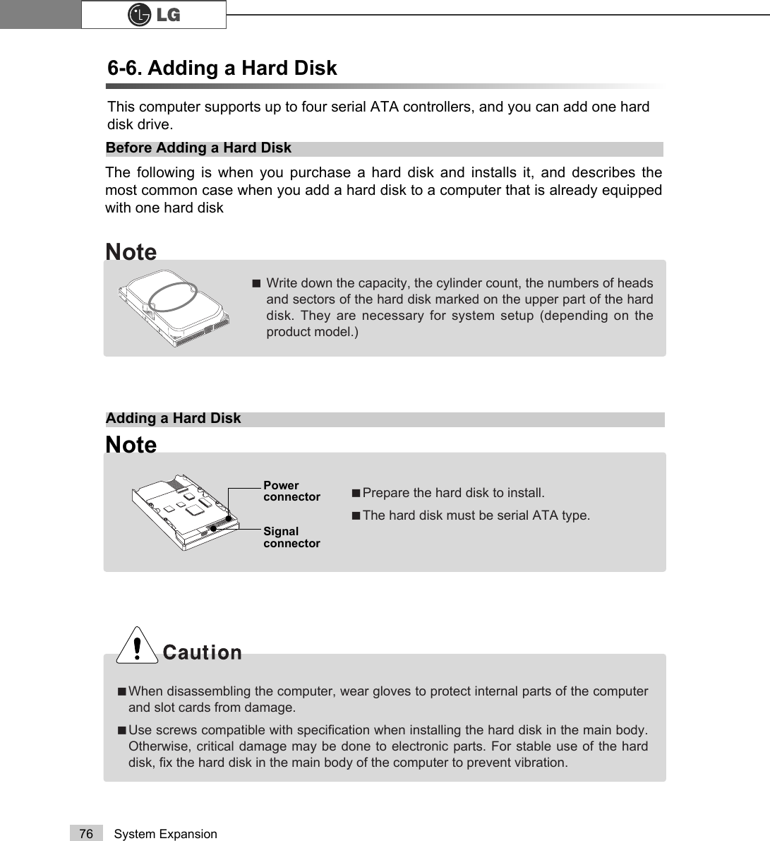
![81System ExpansionConfiguring the Hard Disk (in Factory Setting Status)ⓞSelect the [Start] button on the desk top, and click the [Execute].ⓟInput diskmgmt.msc, and click [OK].ⓠSelect Added Disk 1 on Disk Management screen.Right-click and select [New Loglcal Drive]. ⓡWhen New Partition Wizard screen appears, click the [Next] button.If you partition the hard disk using "diskmgmt.msc" existing data on the hard diskdriver will be deleted. You must carefully partition the hard disk when there is data onthe disk.](https://usermanual.wiki/LG-Electronics-USA/DT-CK.USERS-MANUAL-4-OF-4/User-Guide-570605-Page-18.png)
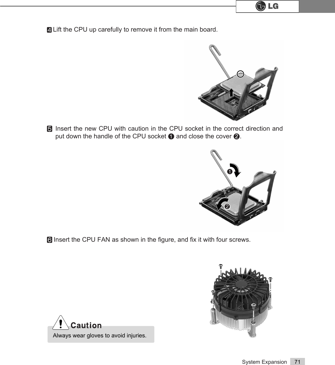
![82 System ExpansionⓢWhen the partition type selection screen appears, select the main partition andclick the [Next] button.ⓣSelect the maximum size, and click the [Next] button.ⓤSelect the Drive Letter and click the [Next] button.You can use as muchspace as you select in theabove window.](https://usermanual.wiki/LG-Electronics-USA/DT-CK.USERS-MANUAL-4-OF-4/User-Guide-570605-Page-19.png)
![83System ExpansionⓥWhen the partition format appears, set the file system, allocation unit, and vol-ume label suitable for the User Environment and click the [Next] button.ⓦThe Partition Wizard has been completed. Click the [Finish] button.ⓧAfter the completion, the additional hard disk will normally function.](https://usermanual.wiki/LG-Electronics-USA/DT-CK.USERS-MANUAL-4-OF-4/User-Guide-570605-Page-20.png)
![Product Specifications86Product Specifications *&.'.0RGHOMouse PS/2 mouse or USB (ball / wheel)Sound Equipped in the main board (MIC connector, speaker connec-tor, line-in connector) and in the extension connector on therear part of the system.System memory128MB or higher. Differs depending on the model. (FK models allocate minimum 8MB or maximum 64MB as thelocal video memory [frame buffer] using a built-in VGA.)USB Equipped in the main board (four) and in the front (two).Serial I/O Installed in the main board. (one 9-pin connector).Parallel I/O One printer port (25pins)Extension slot One PCI-E 16x slot, One PCI-E 1x slot, Two PCI slots.Product size Width 136 x Height 354 x depth 378(mm)Power spec 100~127 / 200~240VAC, 5A / 4A, 50/60Hz or200~240VAC. 4A, 50/60HzFront I/O Two USB ports and audio ports (SPEAKER-OUT and MIC-IN)Video Equipped in PCI-E 16x video card (one 15-pin connector) or inthe main board.Keyboard PS/2 keyboard (104keys)Hard disk drive 40 GB or higher (Serial ATA type).Cache memory 256KB/512KB or 1024KB L2 cache is equipped in the CPU. CPUSupports Pentium4/ LGA775 2.8/3.0/3.2/3.4/3.6 GHz or higher (FSB:533/800MHz) /H. Temperature:Average temperature:77ĕ(25ËOperating temperature:41ĕ~95ĕ(5~35ËStorage temperature:-4ĕ~131ĕ-25~55ËHumidity:Average humidity:60%(RH) Operating humidity:30%~80%(RH)/Storage humidity:30%~80%(RH)Environmental requirementÚÚSpecifications below differ depending on the models.](https://usermanual.wiki/LG-Electronics-USA/DT-CK.USERS-MANUAL-4-OF-4/User-Guide-570605-Page-23.png)