LG Electronics USA DT-CK PERSONAL COMPUTER User Manual CKDK
LG Electronics USA PERSONAL COMPUTER CKDK
Contents
- 1. USER MANUAL 1 OF 4
- 2. USER MANUAL 2 OF 4
- 3. USER MANUAL 3 OF 4
- 4. USERS MANUAL 4 OF 4
USERS MANUAL 4 OF 4

64 Reinstallation of Drivers
You must install a sound driver to listen to music files and CDs on the computer. A
sound driver basically comes out with the computer. If it has to be reinstalled,
however, follow the process below.
5-2.Reinstalling Sound Driver
ⓞTurn on the computer and the monitor.
The video driver displays on the monitor data stored on the computer. The video
driver is included in basic specification of the computer. However, in the case that
it is necessary to reinstall the video driver, carry out the following process.
5-3.Reinstalling Video Driver
ⓞTurn on the computer and the monitor.
ⓟInsert LG GILJABI CD in the CD-ROM driver. Select the sound driver to install
from the list.
ⓠThe driver installation process will start. Follow instructions on the screen.
ⓟInsert LG GILJABI CD in the CD-ROM driver. Select the video driver to install
from the list.
ⓠThe driver installation process will start. Follow instructions on the screen.
ãWhen the computer uses the Intel Onboard Video, some games and programs that does
not support Screen Rotation may not be executed on the screen. When this happens,
disable the Screen Rotation.
Note

65Reinstallation of Drivers
System Expansion
66
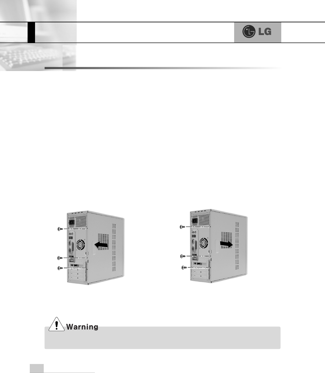
6-1. Opening the computer case
Always consult with your service representatives before opening the computer case.
Note the following when opening the computer cover.
Opening the computer cover Closing the computer cover
ãQuit all programs in use.
ãTurn off the computer and the monitor before disconnecting the power.
ãKeep magnetic tools (for example, drivers) away from the computer since parts
inside the computer are electrically charged and sensitive to magnetic force.
ãInstall the computer in a clean, easily-accessible place.
ãA small electric shock inside the computer may cause operational problems.
Before touching the computer, put hands on an unpainted metallic surface for two
or three seconds to remove static electricity before opening the cover.
ãWhen disassembling the computer, wear gloves to protect internal parts of the
computer and slot cards from damage.
6.System Expansion
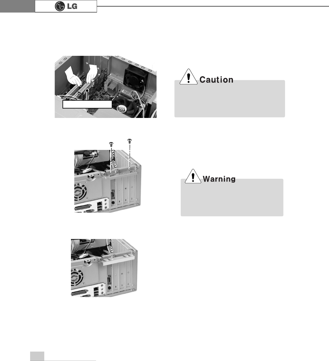
Before assembling the computer cover, check if there is any metallic material left inside the
main body. A metallic substance inside the main body can cause an electric shock or fire.
Remove 3 screws from the cover and
then push the cover as the direction of
the arrow.
Push the cover in the direction of
arrow as it aligns the groove of com-
puter cover with body shown on the
picture and fasten 3 screws.
System Expansion 67
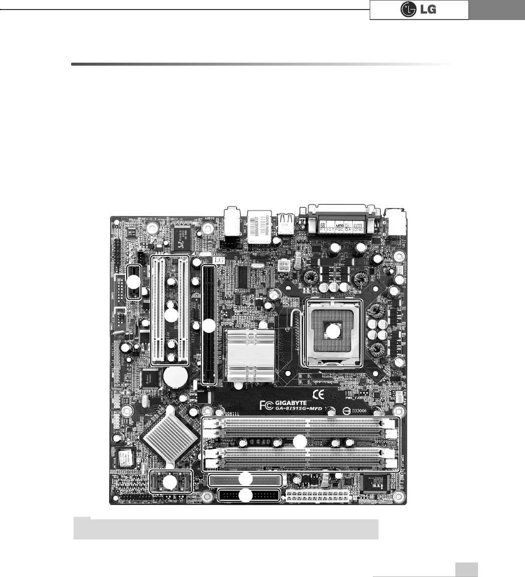
6-2. Main Board
The model name of the computer depends on the main board type. When extend-
ing the computer, check the model name on the label attached on the rear panel
of the computer and the following. Before extending the computer, check the main
board first
℘Expansion slot (PCI-E x1)
ℙ
ℙExpansion slot (PCI)
ℚExpansion slot (PCI-E x16)
ℛ
ℛCPU socket (with Pentium4 Á16
LGA 775)
ℜℜMemory socket (DIMM)
ℝFloppy disk connector
℞
℞Hard disk/CD-ROM connector
℟Serial ATA-type hard disk con-
nector
ãThe main board in your computer may look different from the picture.
Note
℘
ℙℚℛ
ℜ
ℝ
℞
℟
System Expansion68
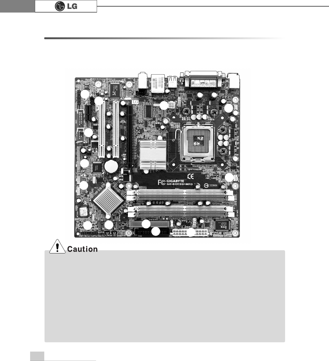
6-3. Internal Connectors
Connectors are configured in a certain way at the factory, and connectors show the
connection status between the main board of the computer and peripherals.
(Connector configuration depends on product models.)
ãBefore separating the connector, check the connection state of the connectors and leave a
record on the state.
ãLink the floppy disk driver connector and the hard disk/CD-ROM connector in the correct
direction.
ãThe Pin Number and the color of the connector cable must match. Otherwise, an error may
occur in the computer.
ãRisk of explosin if battery is replaced by an incorrect type. Dispose of used batteries
according to the instructions.
ãThere is a risk of explosion if the backup(standby) RTC battery is replaced by an incorrect
type. Dispose of used backup(stadby) RTC battery according to your local ordinances or
regulation.
℘ℚℜ
ℛ
ℝ
℞
℟
℠℡
⌅
⌆
⌇
ℙ
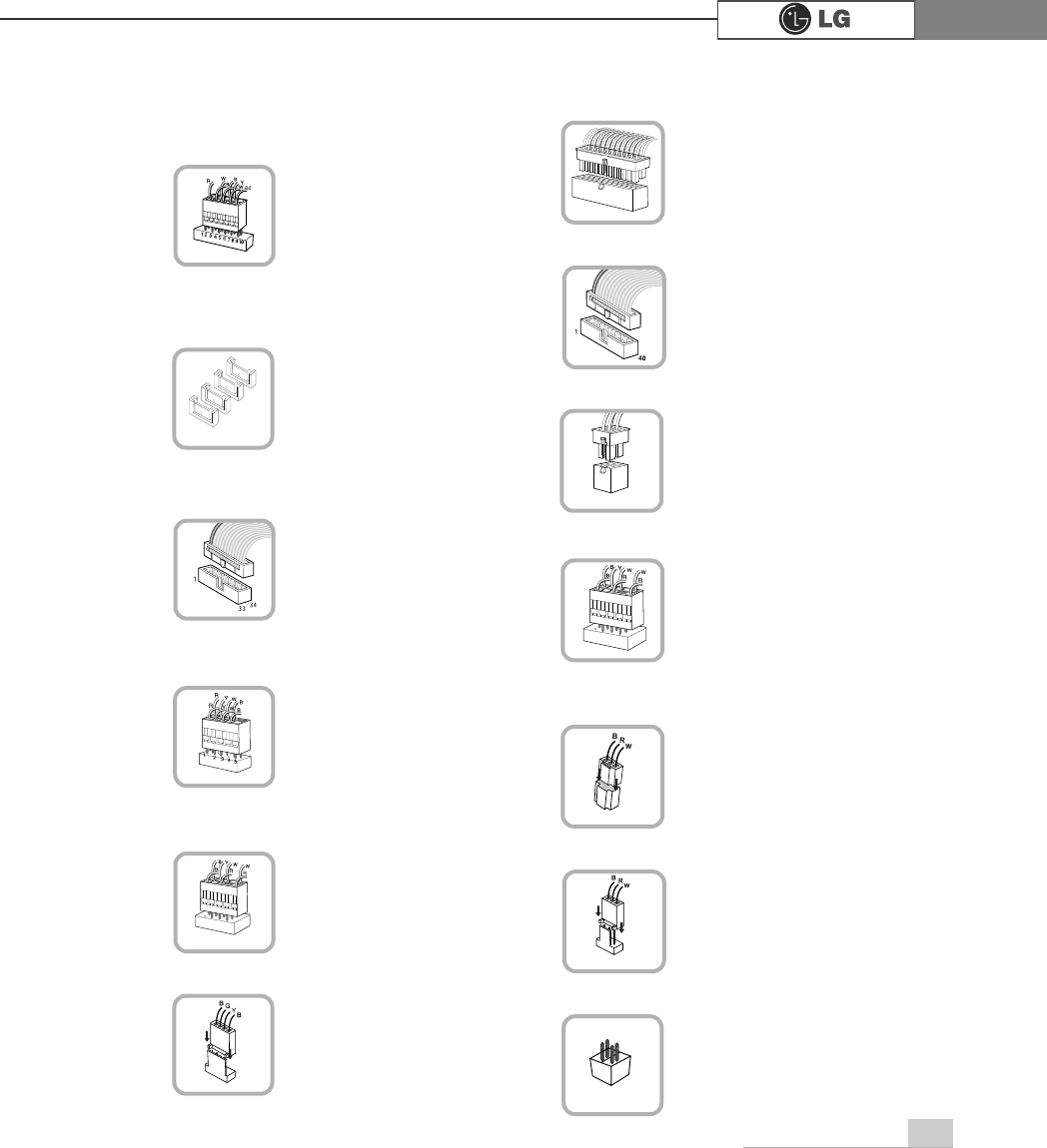
System Expansion 69
℘Power on/off and power/hard disk
operation status indication lamp
connector (F_PANEL)
Connects the floppy disk
driver.
ℜ
ℜFloppy disk driver connector
(FDD: 34 pins)
ℙPower connector (ATX: 24 pins)
Connects the power
supply unit.
ℝ
ℝPower connector (ATX_12V: 4 pins)
&RQQHFWVWKHIURQW86%
.
℞
℞USB connector (F_USB1, F_USB1:
10 pins)
Connects camcorders
supporting IEEE1394.
℟1394 connector (F1_1394: 10 pins)
Connects a front ear-
phone and microphone.
℠
℠Audio connector (AZALIA_FP: 10
pins)
S_ATA connector is
linked to the hard disk
driver.
Connects the power
on/off switch and the
power/hard disk operation
status indication lamp.
CDROM, hard disk
driver.
Connects the power
supply unit.
ℚHard disk connector (S_ATA1,
S_ATA2, S_ATA3, S_ATA4: 7 pins)
ℛ
ℛOptic drive connector (IDE : 40 pins)
Connects the SPDIF
port with optic output
feature.
℡SPDIF connector (SPDIF_LG: 3 pins)
Provides power to the
CPU fan.
⌅
⌅CPU fan (CPU_FAN: 4 pins)
Connects the VFD.
⌇VFD connector
Installed at the bottom
(rear panel) of the system,
and connects the VFD.
⌆
⌆System fan (SYSTEM_FAN: 3 pins)
F_PANEL
ATX
S_ATA
IDE
FDD
ATX
USB
F1_1394
AZALIA_FP
SPIF
CPU_FAN
SYSTEM_FAN
VFD
System Expansion70
6-4 Replacing the CPU
To upgrade the CPU for better performance of the computer, you need to replace the
CPU first. Check the location and the type of the CPU in the main board, and do the
following. (Shape of the CPU FAN and CPU replacement methods may differ by
model.)
Align the groove to the right position,
pins can easily be broken.
℘
ℙ
ⓞ
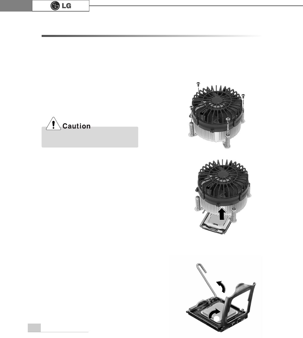
Remove four screws fixing the CPU fan as shown in the figure.
ⓠ
Turn the CPU socket handle as shown in the figure of Step ℘, and open the cover
as shown in the figure of Step ℙ.
ⓟ
Remove the CPU fan as shown in the figure.
System Expansion 71
Always wear gloves to avoid injuries.
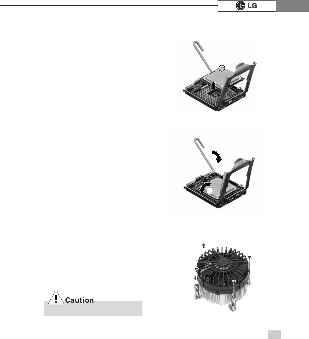
ⓡ
Lift the CPU up carefully to remove it from the main board.
ⓢ
Insert the new CPU with caution in the CPU socket in the correct direction and
put down the handle of the CPU socket ℘and close the cover ℙ.
℘
ℙ
ⓣ
Insert the CPU FAN as shown in the figure, and fix it with four screws.

72 System Expansion
6-5. Expanding the Computer Memory
You may expand the memory capacity, if needs be.
About Memory
This system uses a 240-pin memory module called Double Data Rate-2 (DDR-2),
not the old 184-pin memory module called Double Data Rate (DDR). The main
board can support maximum 2GB in memory.
Before Expanding the Memory
ãWhen disassembling the computer, wear gloves to protect internal parts of the
computer and slot cards from damage.
ãAs the memory is sensitive to static electricity, be careful with the static electrici-
ty when removing or installing a memory.
ãCheck the specifications of the current memory and the new memory before
expanding the memory.
ãUnlike SIMM, DIMM is of 64 bits. Therefore, single DIMM can function, and you
can add DIMM by one.
ãWindows 95, 98SE, and ME support maximum 512MB. Installing a memory with higher
capacity than 512MB may cause malfunctioning of the system.
Note
Note
ãWhen expanding the memory, add a memory with the same specification (DDR-2
SDRAM for 1.8V). (The shape of the memory may differ depending on the product
model.)
ãThe DDR-2 memory provides greatly improved transmission rate than existing memo-
ries, and is differently shaped.
'
''5
73System Expansion
Refer to the following when expanding memory.
ãThis computer supports PC3200/4300, DDR-2 specification.
ãWhen expanding the memory, use only unbuffered DDR SDRAM DMM
ãWhen inserting two same memories in same-colored DIMM slots, the computer will oper-
ate in Dual Channel mode.
FSB Frequency
400/533 MHz
Usable Memory
PC3200/4300-DDR-2 SDRAM 400/533MHz
Preparing a Memory
Before purchasing memory, study the specifications and features of the current
memory.
Specification : PC3200/4300 (240-pin DDR-2 SDRAM)
Rate : 400MHz (200MHz Á2), 533MHz (266MHz Á2)
Type : 256MB, 512MB
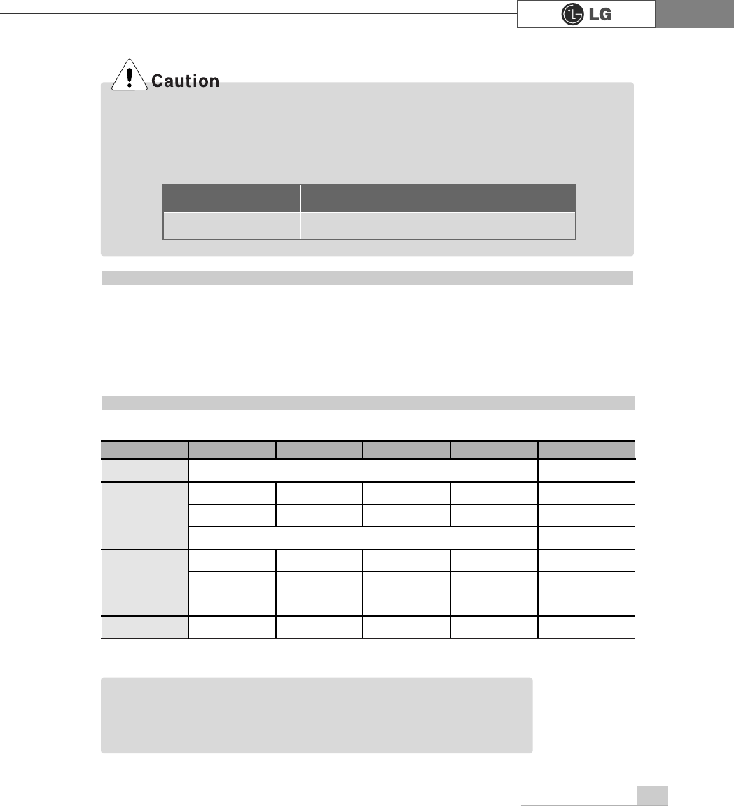
Composing the Memory
Total memory capacity
DIMM 1 DIMM 2 DIMM 3 DIMM 4
DUAL/SINGLE
SINGLE
DUAL
DUAL
SINGLE
DUAL
DUAL
DUAL
DUAL
512MB
256MB 256MB
256MB 256MB
256MB
1024MB
256MB 256MB 256MB 256MB
512MB 512MB
512MB 512MB
2048MB 512MB 512MB 512MB 512MB
512 (One out of four slots)
256 (One out of four slots)
ãThe computer operates faster in Dual Channel mode.
ãUse the same memory to operate the computer in Dual Channel mode.
ãIt is recommended to use Dual Channel mode.
Note
74 System Expansion
Main board configuration, memory socket and memory type may differ by model.
ⓞLoosen the screws on the rear panel
of the computer, and remove the
cover.
ⓟRelease the latches from both flanks of the memory. The memory will be
removed automatically.
Replacing the Memory
ãBefore opening the computer cover,
turn off the power and all peripherals
connected to the computer.
Disconnect all power cables.
Note
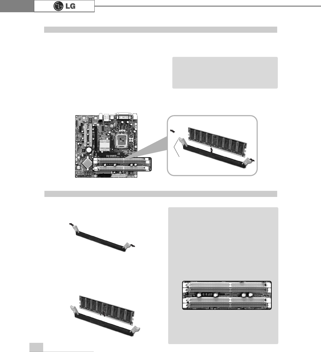
ⓞ
Lay the latches outwards from the
memory socket.
ⓟ
Insert the memory (DIMM) vertically in
the socket in line with the grooves as
shown in the figure.
Installing Memory
ãWhen using a DDR memory, the
memory must be installed in each
channel for Dual Channel mode.
1-3 and 2-4 of dual Channels No. 1 ~ 4
The memory will be automatically
installed even if not latched.
However, it is recommended to fas-
ten the latches until the memory is
completely fixed.
Note
The memory will be automatically
installed even if not latched. However, it
is recommended to fasten the latches
until the memory is completely fixed
latch
℘
ℙ
ℚ
ℛ
75System Expansion
Checking the Expanded Memory
Turn on the power after installing the memory. Then, the computer will detect the mem-
ory so that you don't need to change the system setup. The capacity of the installed
memory is checked as follows.
ⓞConnect the power cord and other cables, and turn on the computer and the moni-
tor. Then, the initial screen to check the status of the computer will appear.
ⓟWhen the following screen appears, press [Esc] key. Then, POST screen will
appear.
ⓠOn the next screen, press [Pause] to freeze the screen temporarily and to check
the Memory Testing : XXXXXX OK part.
ⓡAfter checking the memory, press the [Esc] key. Windows screen will proceed.
ãIn the case that the logo screen is processed too fast to stop, press [Delete] key on the
LG logo screen. Then, select Advanced BIOS Features ĚFull Screen Logo Show
Selectable, and change status from Enabled to Disabled.
Note
$ZDUG0RGXODU%,26Y;;;;;$Q(QHUJ\6WDU$OO\
&RS\ULJKW&$ZDUG6RIWZDUH,QF
%XLOG,'/*;;;;;;;;;;;;;;
0DLQ3URFHVVRU,QWHO53HQWLXP5;3URFHVVRU;;;0+]
0HPRU\7HVW;;;;;;2.
3UHVV'(/WRHQWHU6(783
;;;;;;;;;;;;;;;;;;;;;;;;;
0HPRU\7HVWLQJ;;;;;;2.
76 System Expansion
6-6. Adding a Hard Disk
This computer supports up to four serial ATA controllers, and you can add one hard
disk drive.
The following is when you purchase a hard disk and installs it, and describes the
most common case when you add a hard disk to a computer that is already equipped
with one hard disk
ãWhen disassembling the computer, wear gloves to protect internal parts of the computer
and slot cards from damage.
ãUse screws compatible with specification when installing the hard disk in the main body.
Otherwise, critical damage may be done to electronic parts. For stable use of the hard
disk, fix the hard disk in the main body of the computer to prevent vibration.
Before Adding a Hard Disk
Adding a Hard Disk
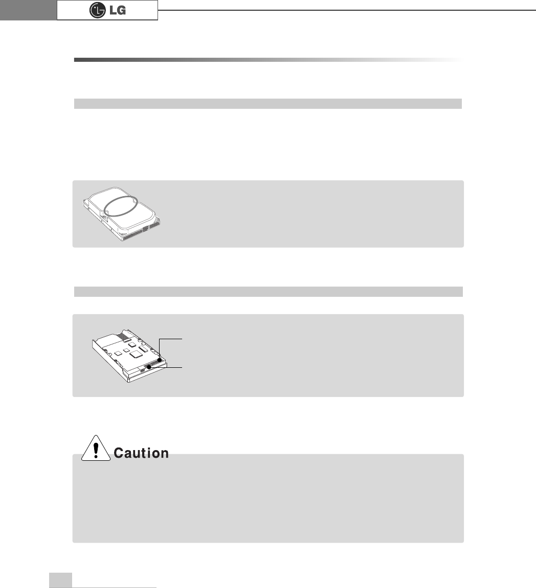
ãWrite down the capacity, the cylinder count, the numbers of heads
and sectors of the hard disk marked on the upper part of the hard
disk. They are necessary for system setup (depending on the
product model.)
Note
Note
ãPrepare the hard disk to install.
ãThe hard disk must be serial ATA type.
Signal
connector
Power
connector
77System Expansion
Adding a hard disk drive
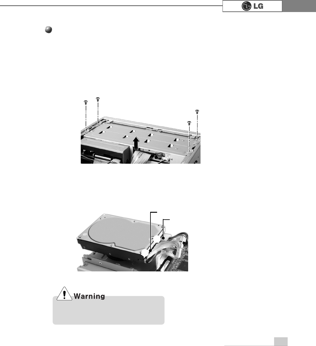
ⓟRemove 4 screws on the hard drive case and open the hard drive case as the
direction of the arrow.
ⓞRefer to Opening the computer case (page 66) to remove the computer case
cover.
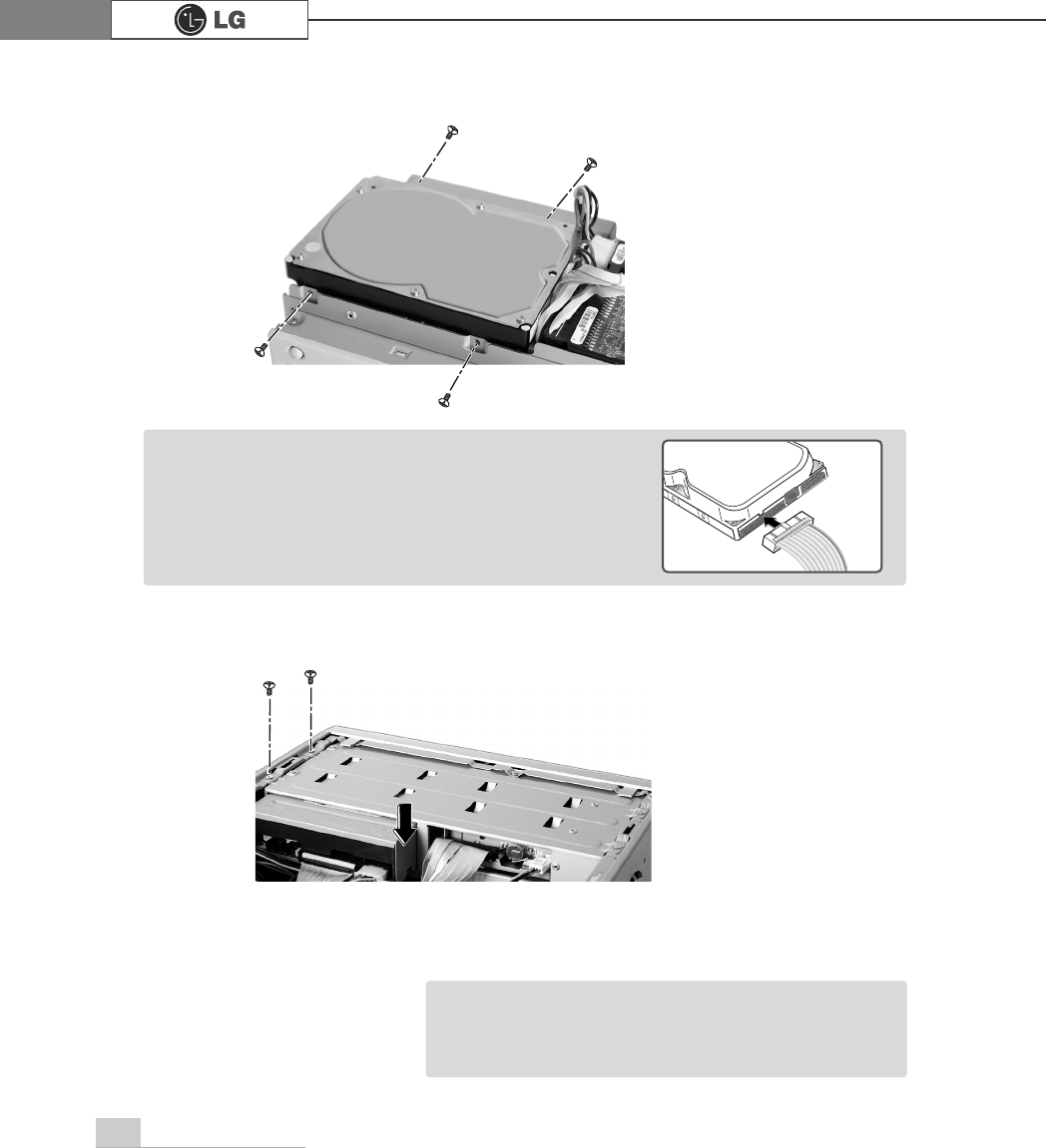
ⓠConnect the power cable connector as shown No1 and the signal cable connec-
tor as shown No 2 to the new hard disk you want to replace in the hard disk
case.
℘
ℙ
power cable
signal cable
Incorrect connection of the signal and
power cord may cause disfunction to the
computer or electrical shock.
78 System Expansion
ⓣRefer to Closing the computer case (page 66) to close the computer case cover.
ⓢFasten 4 screws after installing the hard disk drive as shown on the picture.
ⓡInstall the hard disk drive case to the computer and fasten the 4 screws.
ãIncorrect connection of the power and signal cables to
a hard disk drive may damage the drive.
Note
ãYou should setup and format your computer after
installing the hard disk. Refer to the Hard disk setup
(page82).
Note
79System Expansion
ⓞ
Turn on the computer and the monitor.
ⓟ
While the LG logo screen is on, press [Delete] key.
ⓠ
Then, the initial screen of System Setup menu will appear.
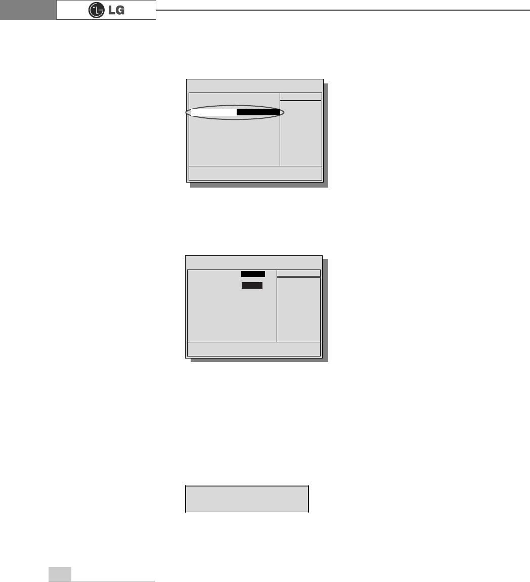
ⓡExecute the initial screen of the System Setup menu, and select Standard
CMOS Features by pressing
>Ⓑ@>Ⓒ@>⒵@
, and
>Ⓐ@
keys. Then, press [Enter].
Hard disk drive setup
3KRHQL[$ZDUG%,26&0266HWXS8WLOLW\
Ě 6WDQGDUG&026)HDWXUHV Ě
3&+HDOWK6WDWXV
Ě $GYDQFHG%,26)HDWXUHV Ě )UHTXHQF\9ROWDJH&RQWURO
Ě $GYDQFHG&KLSVHW)HDWXUHV /RDG2SWLPL]HG'HIDXOWV
Ě ,QWHJUDWHG3HULSKHUDOV 6HW3DVVZRUG
Ě 3RZHU0DQDJHPHQW6HWXS 6DYH([LW6HWXS
Ě 3Q33&,&RQILJXUDWLRQV ([LW:LWKRXW6DYLQJ
(VF4XLW êëè é 6HOHFWOWHP
)6DYH([LW6HWXS
9LUXV3URWHFWLRQ%RRW6HTXHQFH
80 System Expansion
ⓢ
When the following appears, select IDE Channel 0 Salve by pressing
>Ⓑ@>Ⓒ@>⒵@
, and
>Ⓐ@
keys and press [Enter] key.
ⓣ
Press [Enter] key on IDE Channel 0 Slave to set it as Auto, and press [Enter]
key again on IDE HDD Auto-Detection to set it as Slave. Then, the additionally
installed hard disk will be automatically detected.
ⓤTo save changes in System Setup, press the [F10] key.
ⓥWhen the following message appears, press the [Enter] key to restart the computer.
Phoenix-Award BIOS CMOS Set up Utility
Standard BIOS Features
Data (mm:dd:yy) XXX, XXX, XXXX
Time (hh:mm:ss) XX, XX, XX
ĚIDE Channel 0 Master Press EnterXXXXXMB
ĚIDE Channel 0 Slave Press Enter None
ĚIDE Channel 1 Master Press Enter None
ĚIDE Channel 1 Slave Press Enter None
Drive A X.XXM, X.Xin
Drive B None
Video EGA/VGA
Halt On All, But Keyboard.
CPU Type X.XXX.XXX.XX
BIOS Version Build ID :LG
Video Memory X.XX K
System Memory X.XX K
Total Memory X.XX K
Item Help
Menu Level Ě
To auto-detect the
HDD's size, head...on
this channel
êëèé:Move Enter:Select +/-/PU/PD:Value F10:Save ESC:Exit F1:General Help
F5:Previous Values F7:Optimized Defaults
3UHVV(QWHU1RQH
Ě
,'(&KDQQHO6ODYH
IDE HDD Auto-Detection
Press Enter
IDE Channel 0 Slave Auto
Access Mode Auto
Capacity 0 MB
Cylinder 0
Head 0
Precomp 0
Lauding Zome 0
Sector 0
Item Help
Menu Level Ě
To auto-detect the
HDD's size, head...on
this channel
êëèé:Move Enter:Select +/-/PU/PD:Value F10:Save ESC:Exit F1:General Help
F5:Previous Values F7:Optimized Defaults
$XWR
3UHVV(QWHU
6$9(WR&026 DQG(;,7<1"<
Phoenix-Award BIOS CMOS Set up Utility
IDE Channel 0 Slave
81System Expansion
Configuring the Hard Disk (in Factory Setting Status)
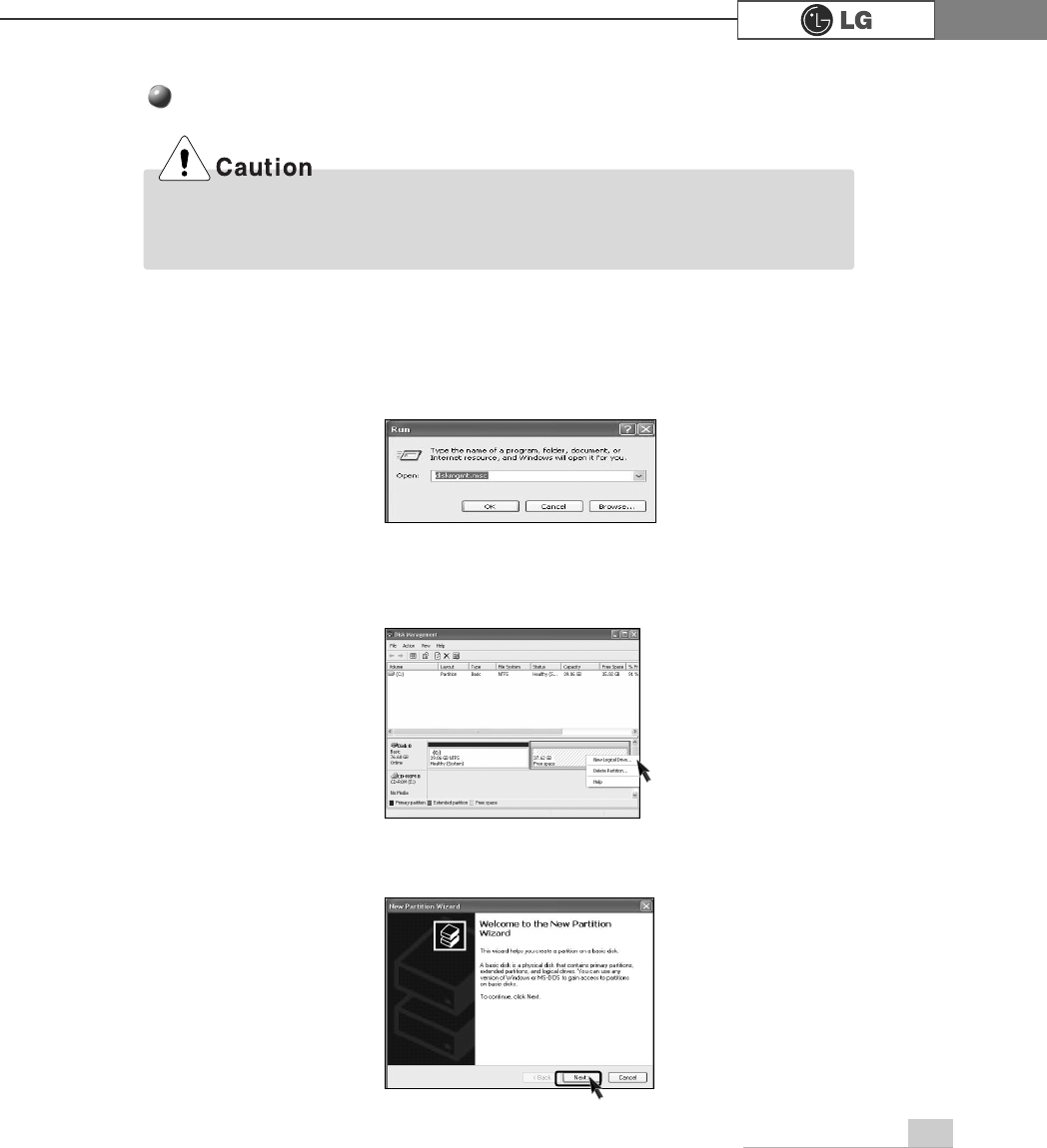
ⓞSelect the [Start] button on the desk top, and click the [Execute].
ⓟInput diskmgmt.msc, and click [OK].
ⓠSelect Added Disk 1 on Disk Management screen.
Right-click and select [New Loglcal Drive].
ⓡWhen New Partition Wizard screen appears, click the [Next] button.
If you partition the hard disk using "diskmgmt.msc" existing data on the hard disk
driver will be deleted. You must carefully partition the hard disk when there is data on
the disk.
82 System Expansion
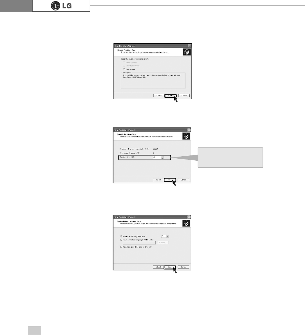
ⓢWhen the partition type selection screen appears, select the main partition and
click the [Next] button.
ⓣSelect the maximum size, and click the [Next] button.
ⓤSelect the Drive Letter and click the [Next] button.
You can use as much
space as you select in the
above window.
83System Expansion
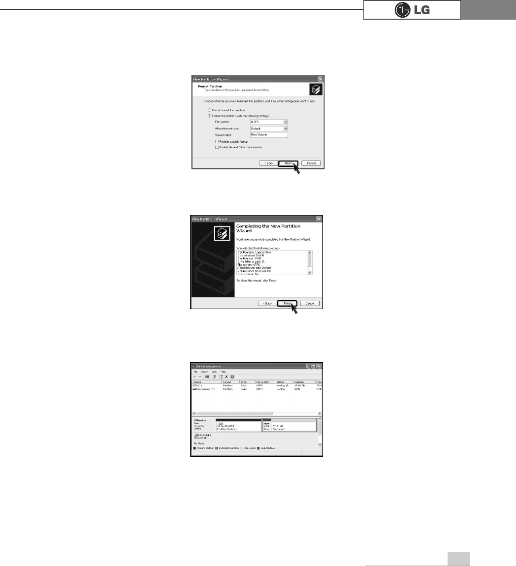
ⓥWhen the partition format appears, set the file system, allocation unit, and vol-
ume label suitable for the User Environment and click the [Next] button.
ⓦThe Partition Wizard has been completed. Click the [Finish] button.
ⓧAfter the completion, the additional hard disk will normally function.
84 System Expansion
ⓥRefer to Closing the computer case to close the case cover of the computer.
ⓦInstall the driver program for the new expansion card.
ⓣFasten 2 screws after installing the extension slot.
ⓢHold the expansion card with both hands and align the expansion card and slot.
Push down evenly to insert the card into the slot.
ⓤClose the cap in the same position as you removed it.
Expansion slot
ãIncorrect installation of an expansion
card may damage the main board
and result in a computer malfunction.
ã
Using the computer without closing
the case may result in fire, electric
shock, injury, and/or damage to the
computer.

85System Expansion
PHPR
Product Specifications86
Product Specifications *
&.'.0RGHO
Mouse PS/2 mouse or USB (ball / wheel)
Sound Equipped in the main board (MIC connector, speaker connec-
tor, line-in connector) and in the extension connector on the
rear part of the system.
System memory
128MB or higher. Differs depending on the model.
(FK models allocate minimum 8MB or maximum 64MB as the
local video memory [frame buffer] using a built-in VGA.)
USB Equipped in the main board (four) and in the front (two).
Serial I/O Installed in the main board. (one 9-pin connector).
Parallel I/O One printer port (25pins)
Extension slot One PCI-E 16x slot, One PCI-E 1x slot, Two PCI slots.
Product size Width 136 x Height 354 x depth 378(mm)
Power spec 100~127 / 200~240VAC, 5A / 4A, 50/60Hz or
200~240VAC. 4A, 50/60Hz
Front I/O Two USB ports and audio ports (SPEAKER-OUT and MIC-IN)
Video Equipped in PCI-E 16x video card (one 15-pin connector) or in
the main board.
Keyboard PS/2 keyboard (104keys)
Hard disk drive 40 GB or higher (Serial ATA type).
Cache memory 256KB/512KB or 1024KB L2 cache is equipped in the CPU.
CPU
Supports Pentium4/ LGA775 2.8/3.0/3.2/3.4/3.6 GHz or higher (FSB:
533/800MHz) /H.
Temperature:Average temperature:77ĕ(25Ë
Operating temperature:41ĕ~95ĕ(5~35Ë
Storage temperature:-4ĕ~131ĕ
-25~55Ë
Humidity:Average humidity:60%(RH)
Operating humidity:30%~80%(RH)/Storage humidity:30%~80%(RH)
Environmental
requirement
ÚÚSpecifications below differ depending on the models.
This equipment has been tested and found to comply with the limits for a Class B
digital device, pursuant to part 15 of the FCC Rules. These limits are designed to
pro-vide reasonable protection against harmful interference in a residential installa-
tion. This equipment generates, uses and can radi-ate radio frequency energy and,
if not in-stalled and used in accordance with the in-structions, may cause harmful
interference to radio communications. However, there is no guarantee that interfer-
ence will not occur in a particular installation. If this equip-ment does cause harmful
interference to radio or television reception, which can be determined by turning the
equipment off and on, the user is encouraged to try to correct the interference by
one or more of the fol-lowing measures:
-. Reorient or relocate the receiving antenna.
-. Increase the separation between the equip-ment and receiver.
-. Connect the equipment into an outlet on a circuit different from that to which the
re-ceiver is connected.
-. Consult the dealer or an experienced radio/TV technician for help.
NOTE
Changes or modifications not expressly approved by the party responsible for com-
pliance could void the user's authority to operate the equipment.