LG Electronics USA DT-EG PERSONAL COMPUTER User Manual EGEM
LG Electronics USA PERSONAL COMPUTER EGEM
Contents
- 1. USERS MANUAL 1
- 2. USERS MANUAL 2
- 3. USERS MANUAL 3
- 4. USERS MANUAL 4
- 5. USERS MANUAL 5
USERS MANUAL 4
System Expansion
66
6-1. Opening the computer case
Always consult with your service representatives before opening the computer
case.
Follow the guidelines below when opening the case.
Opening and closing the computer case
ãQuit all running programs.
ãTurn off the computer and monitor, and unplug and remove the power cords.
ãKeep magnetic objects such as screw driver away from the parts inside the com-
puter.
ãOpen the computer case in a safe, clean area.
ãThe static electricity can damage the parts inside the computer. Touch a bare,
unpainted metal part of the computer for 2~3 seconds to remove the static elec-
tricity before opening the computer case.
ãAlways wear gloves to avoid injury when disassembling the computer.
Make sure that there is no metallic object left inside the computer before closing the case.
There is the risk of electric shock or fire.
6. System Expansion
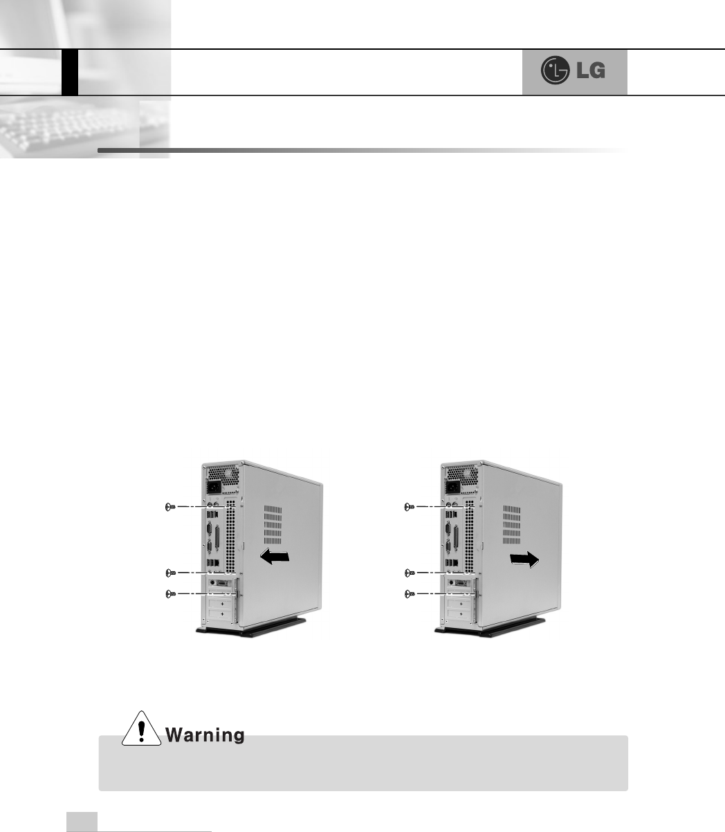
Remove 3 screws from the cover and
then push the cover as the direction of
the arrow.
Push the cover in the direction of
arrow as it aligns the groove of com-
puter cover with body shown on the
picture and fasten 3 screws.
System Expansion 67
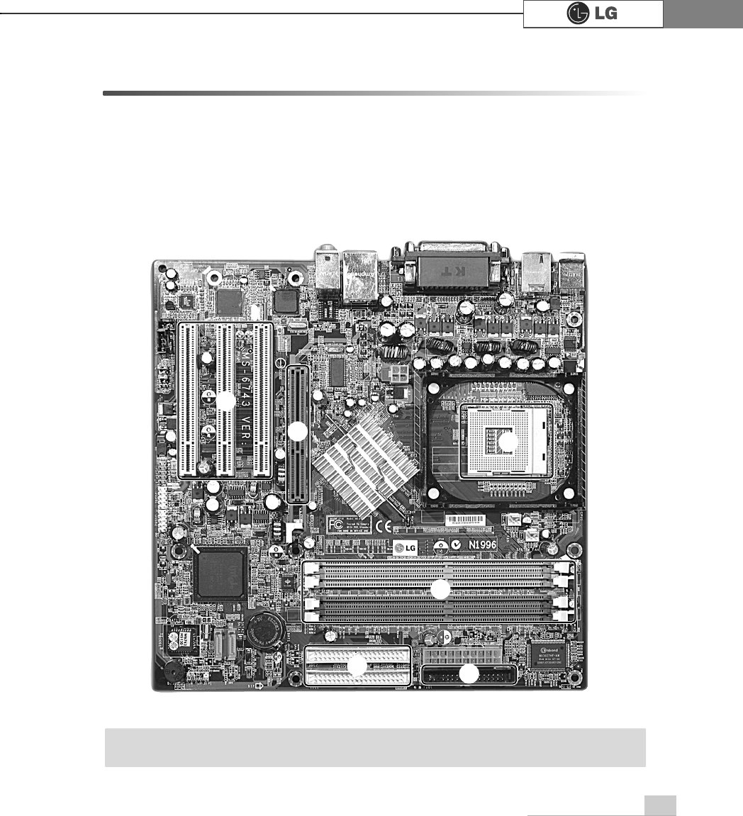
6-2. Main board
The main board determines the model name of your computer. Check the model
name on a label located at the rear of your computer before system expansion.
℘PCI slot
ℙ
ℙAGP slot
ℚCPU socket
ℛ
ℛMemory socket (DIMM)
ℜFloppy disk connector
ℝ
ℝHard disk/CD-ROM connector
℘
ãThe main board in your computer may look different from the picture.
Note
ℙℚ
ℛ
ℜ
ℝ
System Expansion68
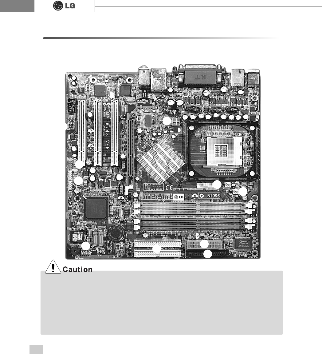
6-3. Connectors
The peripheral devices are connected to the main board through the connectors
shown below. (The main board in your computer may look different from the picture
below)
ãBefore removing the connector, check the status of connection and make a note.
ãAline the groove to the right direction when connecting floppy disk drive connector, hard
disk/CD-ROM connector.
ãMatch the pin number with the color of cable. There is a risk of disfunction to the computer.
ãThere is a risk of explosion if battery is replaced by an incorrect type. Dispose of used batter-
ies according to the instructions.
ãThere is a risk of explosion if the backup(standby) RTC battery is replaced by an incorrect type.
ãDispose of used backup(stadby) RTC battery according to your local ordinances or regulation.
℘ℙ
ℚℛ
℠℡
ℜ
℞
ℝ
℟
System Expansion 69
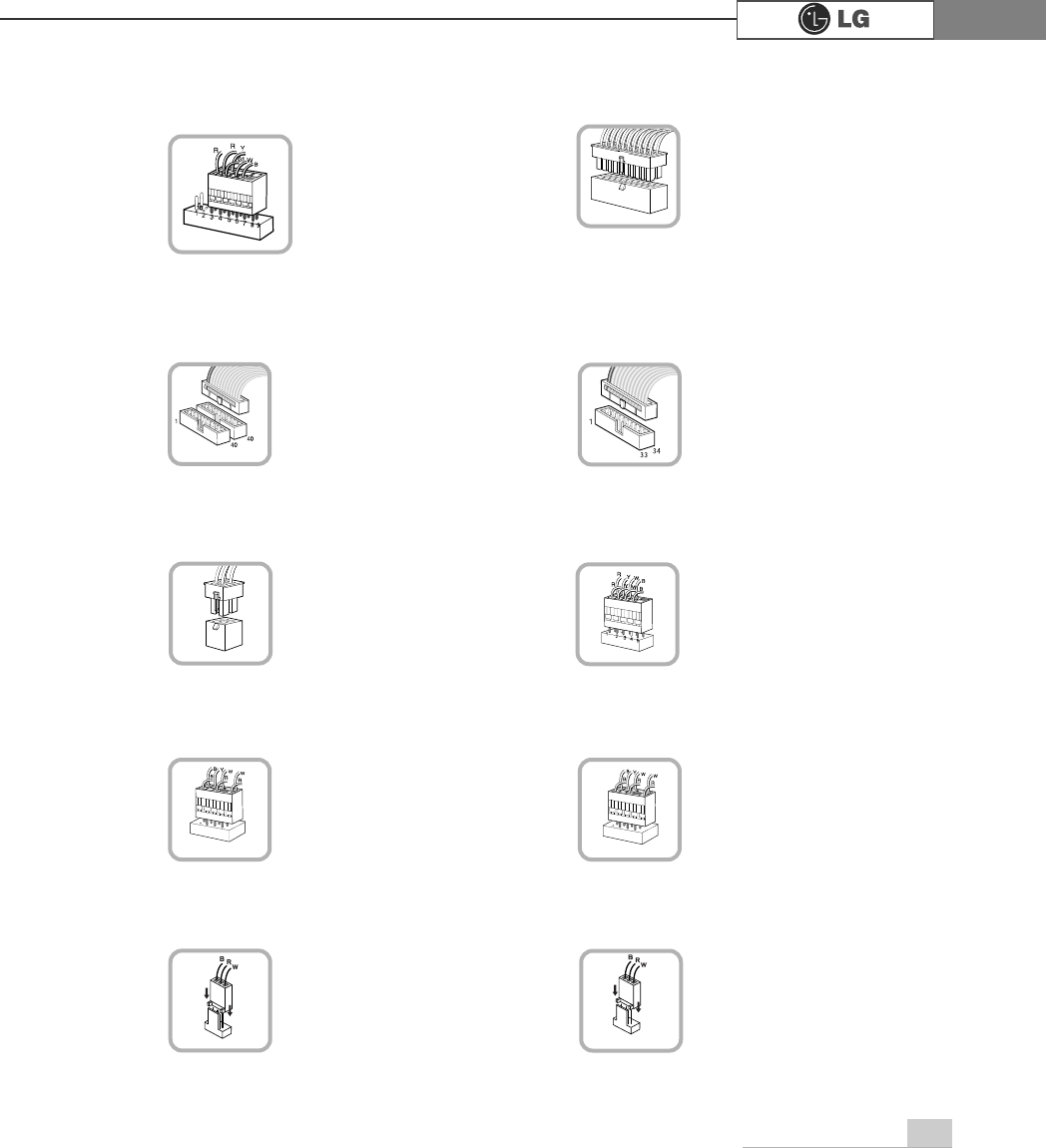
℘Power switch, power/ hard disk activity
LED connector (JFP1)
connects to the power
supply.
ℜPower connector(JPW1: 4 pins)
connects to the power.
ℙPower connector (CONN1: 20 pins)
connects to the USB on
the front of the comput-
er.
ℝUSB connector(JUSB1: 10 pins)
connects power switch
and hard disk activity
LED .
JFP1
ATX1
JPW1 JUSB 1
connects to the IEEE
1394(7 pins) on the
front of the computer.
℞IEEE1394 connector(J1394 : 7pins)
J1394
connects to the head-
phone and microphone
jacks on the front of the
computer.
℟Audio connector(JAUD1: 7 pins)
JAUD1
connects and supplies
power to the CPU fan.
℠CPU fan(CPU_FAN: 3 pins)
CPU_FAN
IDE connector connects
hard disk and CD-ROM
drive. If only one hard disk
is connected, it should be
connected to IDE1 hard
disk connector.
connects to the floppy
disk drive.
ℚHard disk/CD-ROM drive connectors
(IDE1, IDE2: 40 pins)
ℛFloppy disk drive
connector(FDD1: 34 pins)
IDE1 IDE2 FDD1
connects and supplies
power to the system fan
at the bottom of the
computer.
℡System fan (SYSTEM_FAN)
SYSTEM_FAN
System Expansion70
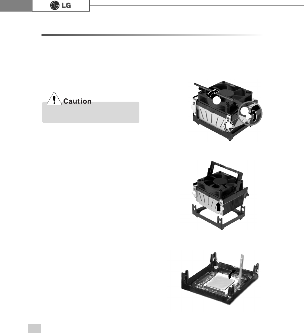
6-4 Replacing the CPU
The shape and replacement method of the CPU fan may be different depending
on the model.
ⓞ
Clamps on both sides of the CPU fasten the fan tightly to the CPU socket.
raise the handle℘, release the clamps, and then spread them outwardℙ.
ⓟ
After releasing the clamps, lift and remove the CPU fan from the socket.
ⓠ
Raise the handle on the CPU socket to unlock the CPU.
Align the groove to the right position,
pins can easily be broken. ℙ
℘
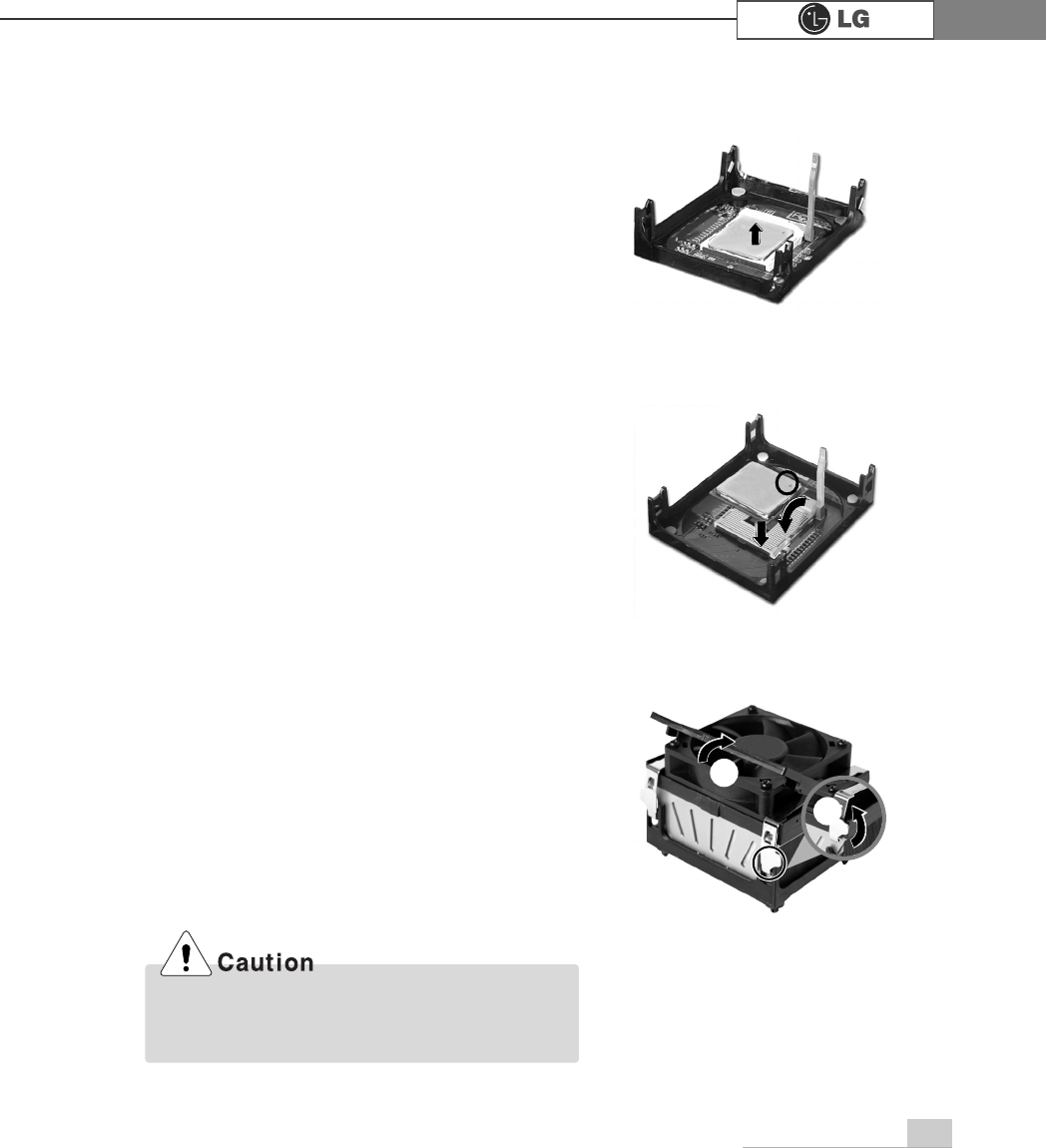
System Expansion 71
ⓢAlign the identifying marks at the corners of the new CPU and socket, and careful-
ly install the CPU in the socket. Lower the handle to lock the CPU in place.
ⓣLower the handle as shown picture℘and lock the clamps as shown picture ℙ.
ⓡLift the CPU straight up. Be careful not to damage the pins at the bottom of the
CPU.
In a specific system, clamps are not fully open.
Raise the CPU fan from the fully opened space.
To assemble it, install from the opposite side.
ℙ
℘
72 System Expansion
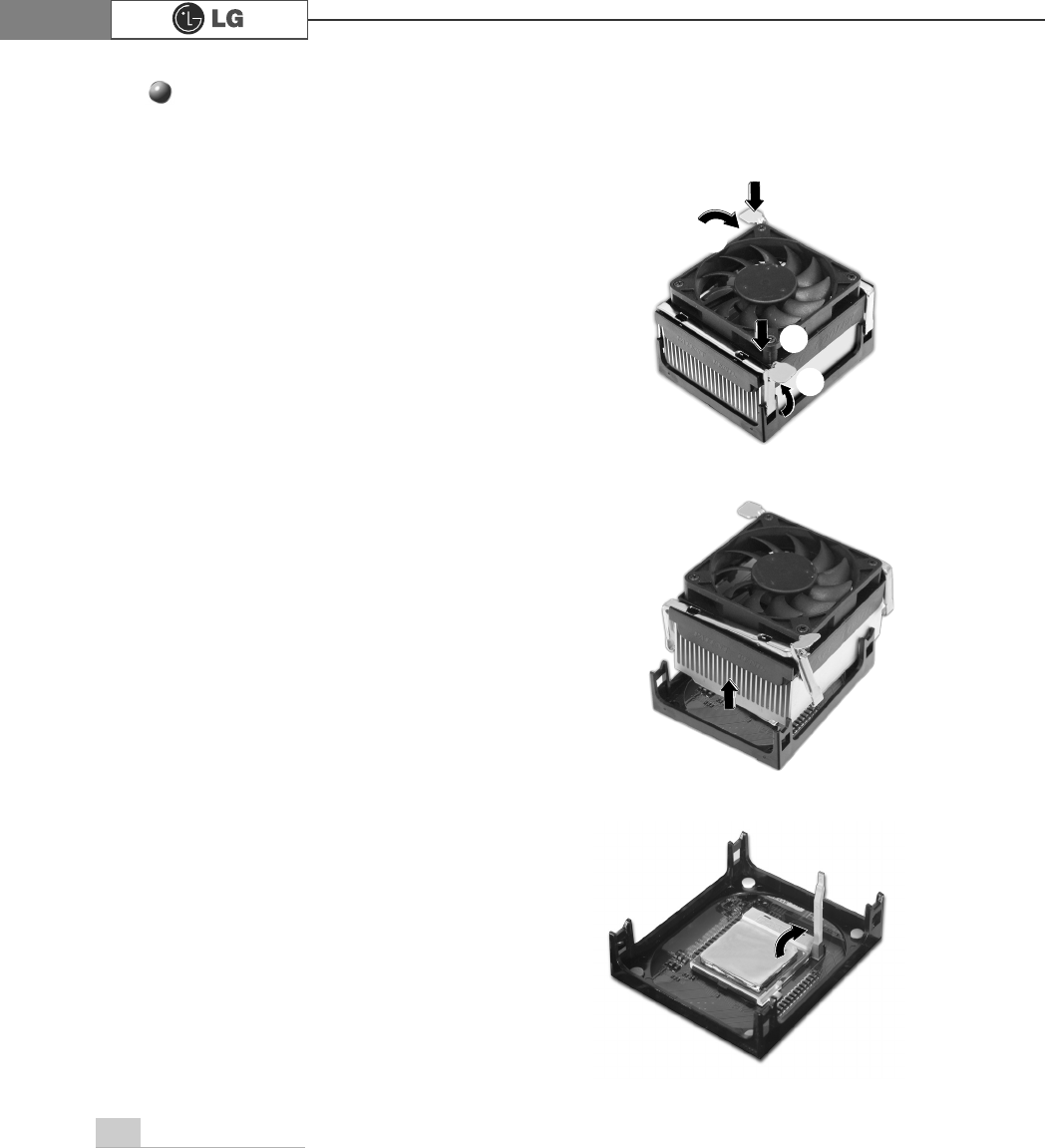
Replacing CPU
ⓞWhile pressing the both sides of the clamps as ℘, raise the fan to the direction
of ℙto release the clamps.
ⓟAfter releasing the clams, raise the CPU fan to remove.
ⓠRelease the CPU socket as the direction of arrow.
℘
ℙ
℘
ℙ
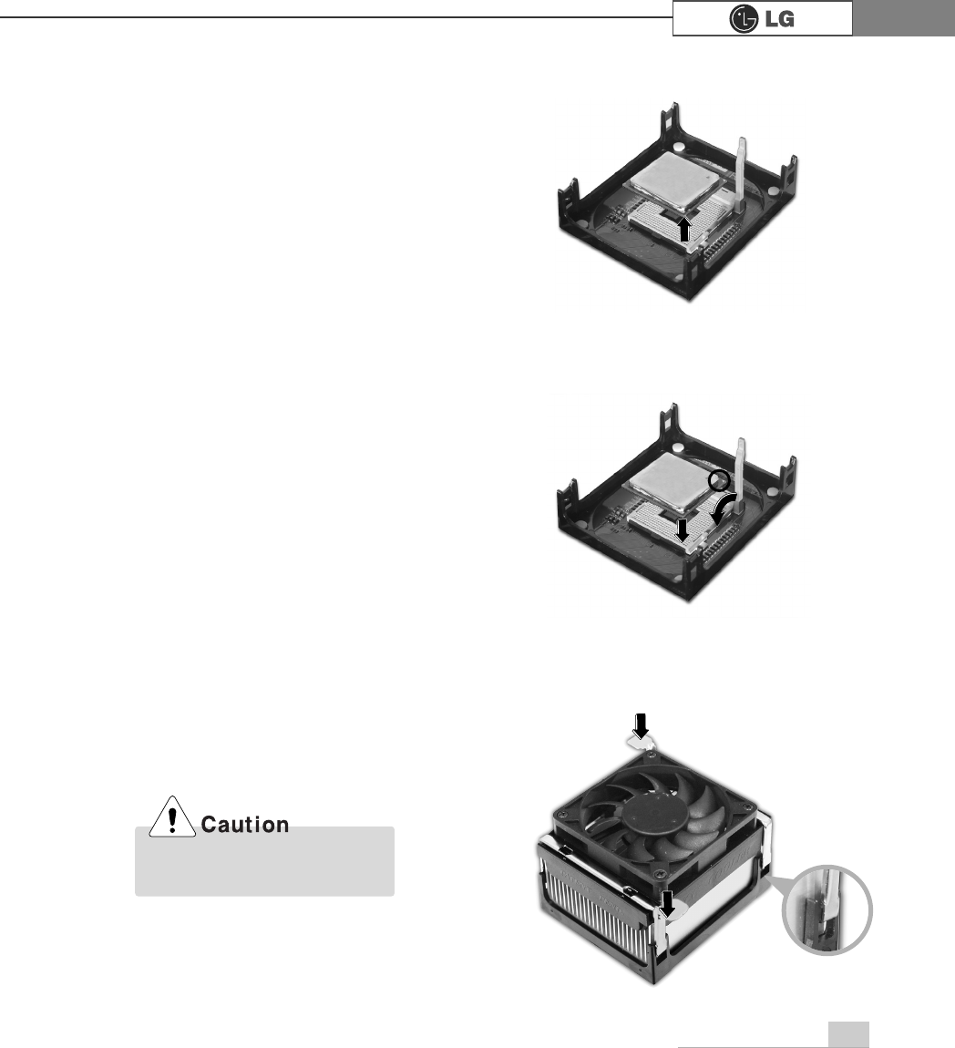
73System Expansion
ⓡRaise the CPU as the direction of arrrow.
ⓢAlign the identifying marks at the corners of the new CPU and socket, and care-
fully install the CPU in the socket. Lower the handle to lock the CPU in place.
ⓣPush the both side of clamps after align the grooves to the clamps.
Please gentely push the
clamps not to make it broken.
System Expansion74
6-5. Increasing the memory
If you run out of memory while using the computer, you may want to increase the
amount of memory in your computer.
About memory
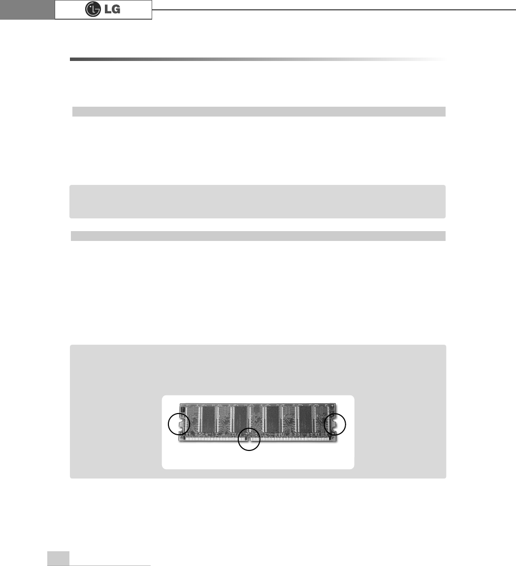
Your computer uses DDR(Double Data Rate) SDRAM DIMM(Dual In-Line Memory
Module) with 184 pins. Your computer supports Unbuffered DDR SDRAM DIMM of
256MB up to 512MB in size in each socket, and 2GB total.
Before increasing the memory
ãAlways wear gloves to avoid injury when disassembling the computer
ãStatic electricity can damage memory modules be sure to minimize the static
electricity when replacing memory.
ãMake sure to replace the memory of the same type as the installed memory.
ãDIMM is different from SIMM in that it is configured for 64 bit operation; there-
fore, your computer can operate with only one DIMM installed.
ãWindows 95, 98SE, ME supports memory up to 512MB total. Increasing the memory
beyond 512MB in these systems may cause errors while using the computer.
Note
ãUse a 2.5V DDR SDRAM DIMM.(The shape of the memory may be different depending
on the model) DDR SDRAM enhances the rate of data transmission of the SDRAM and
looks different from SDRAM.
Note
DDR
System Expansion 75
Purchasing a memory
Check the type of memory installed in your computer and refer to the memory configura-
tion chart before purchasing a memory.
Specification: PC2700/3200(184 pin DDR SDRAM DIMM)
Speed : 333MHz(166MHz X 2), 400MHz(200MHz X 2)
Size : 256MB, 512MB
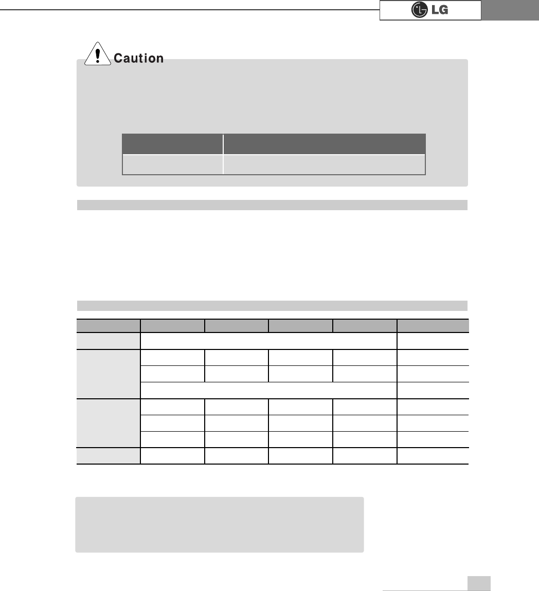
Memory configuration chart
Total memory DIMM 1 DIMM 2 DIMM 3 DIMM 4
DUAL/SINGLE
SINGLE
DUAL
DUAL
SINGLE
DUAL
DUAL
DUAL
DUAL
512MB
256MB 256MB
256MB 256MB
256MB
1024MB
256MB 256MB 256MB 256MB
512MB 512MB
512MB 512MB
2048MB 512MB 512MB 512MB 512MB
512 (1/4)
256
ãYour computer supports PC2700/3200 DDR memory.
ãUse Unbuffered DDR SDRAM DIMM only to increase the memory.
ãDual channel mode operates when each identical memory is installed in the same color
of DIMM slot.
FSB Frequency
533/800MHz
Supported memory type
PC2700/3200-DDR SDRAM 333/400MHz
ãDual channel improves the efficiency of the system.
ãEach identical memory should be used for dual channel setting.
ãDual channel setting is recommended.
Note
System Expansion76
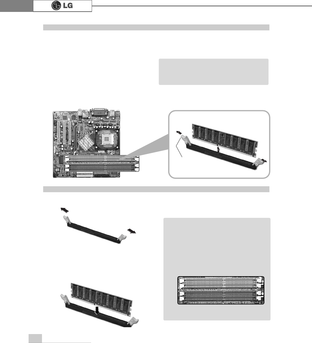
The main board configuration, memory socket, and the shape of memory may be
different depending on the model.
ⓞRemove the screws on the real of
the computer, and open the com
puter case.
ⓞ
Pull the latch on each side of a memory socket.
ⓟPull the latch on each side of a memory socket to release the memory.
Replacing the memory
ⓟ
Align the notch at the bottom of the
memory with a protrusion in the middle
of the socket, and then insert the
memory straight down.
Installing a memory
Latch
ãBefore opening the case, turn off the
computer and peripheral devices, and
remove the power cords.
Note
ãFor dual channel system, each mem
ory should be installed in independent
slot(1&3 slot or 2&4 slot) when using
DDR Memory
It is recognized as a single channel if
there is a difference between dual
channel 1 and 3, 2 and 4.
Note
℘
ℙ
ℚ
ℛ
Firmly push the latch to lock the memory.
System Expansion 77
Checking the size of the installed memory
The computer automatically recognizes the newly installed memory; therefore,
you do not need to change the system setup. Follow the instruction below to
check the size of the installed memory.
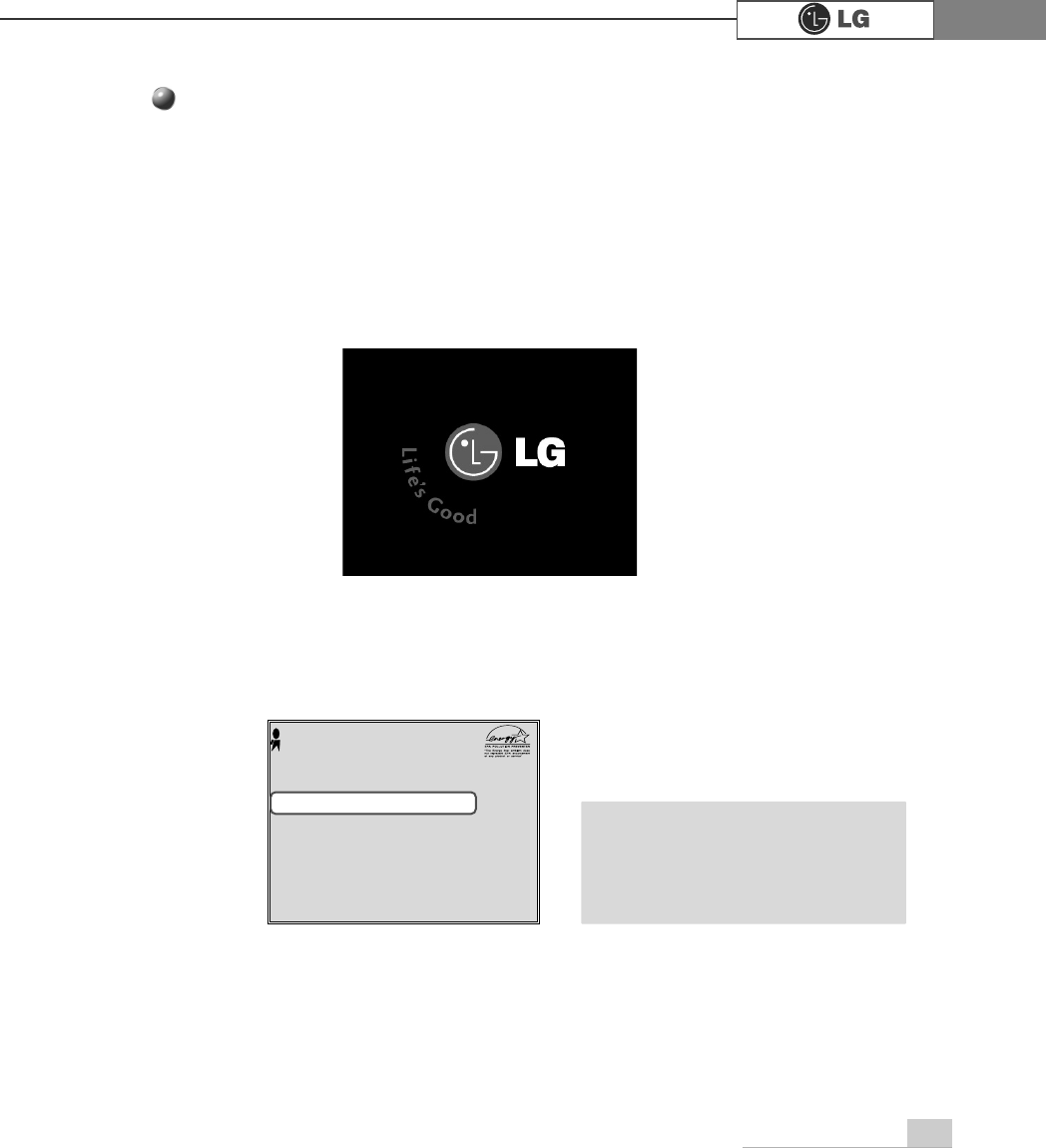
ⓞConnect the power cord and other devices, and turn on the computer and monitor.
The following screen appears to inspect the status of the computer.
ⓟIf the following screen appears, press [Esc]. POST screen appears.
ⓠIf the following screen appears, press [Pause] key to pause the screen. Make
sure [Memory Testing : XXXXXX OK] appears.
ⓡAfter check the memory, press [Esc]. Windows screen appears.
Award Modular BIOS vX.XXXX, An Energy Star Ally
Copyright(C) 1984-2004, Award Software, Inc.
Build ID : LG XXXX XX.XX XX:XX:XX
Main Processor : Intel(R) Pentium(R) X Processor XXXMHz
Memory Test : XXXXXX OK
Press DEL to enter SETUP
XX/XX/XX-XXXX-XXXX-XXXXXXXXX-XX
0HPRU\7HVWLQJ;;;;;;2.
ã
To stop the logo screen for a moment,
press [Delete] key ⎀Advanced BIOS
Features ⎀Full Screen Logo Show
Selectable, and then select Disable.
Note