LINKSYS WRT54AG Wireless A/G Broadband Router User Manual WRT54AG ug Rev NC
LINKSYS LLC Wireless A/G Broadband Router WRT54AG ug Rev NC
LINKSYS >
Contents
- 1. Users Manual 1
- 2. Users Manual 2
- 3. Users Manual 3
- 4. Users Manual 4
Users Manual 3
Dual-Band Wireless A/G Broadband Router
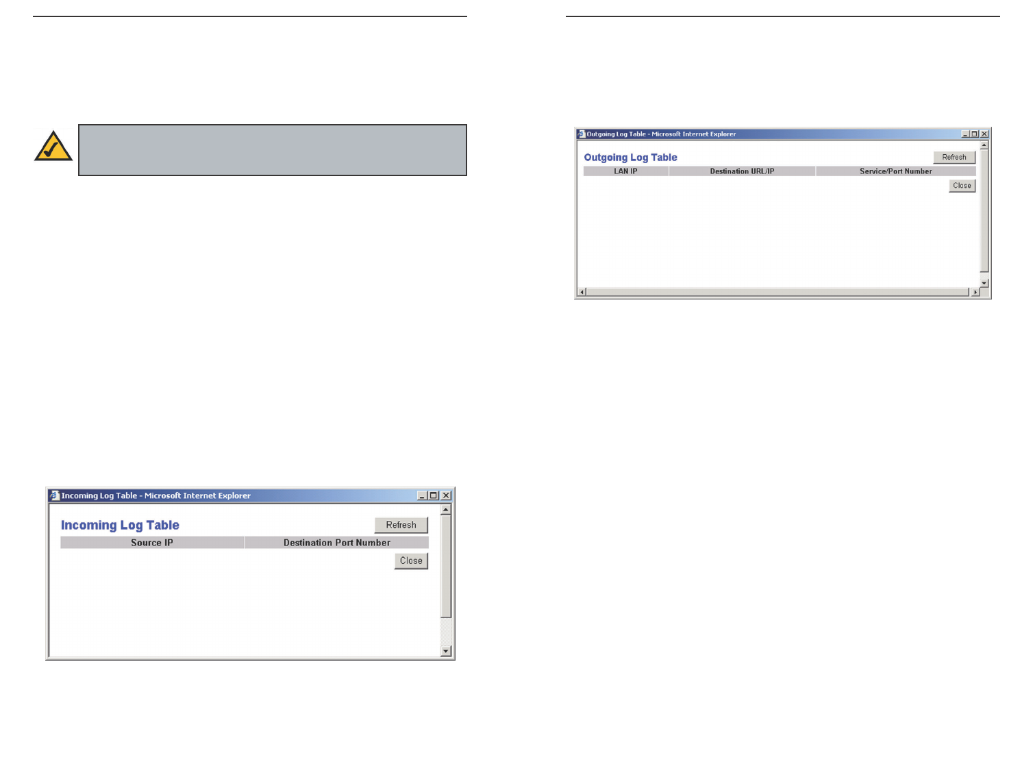
The Incoming Access Log gives you a log of all the incoming Internet traffic,
displaying the Source IP address and Destination Port Number of the Router
for each activity (see Figure 6-14). Click the Refresh button to update the logs.
Click the Close button to return to the System screen.
The Outgoing Access Log gives you a log of all outgoing Internet traffic. For
each activity, it displays the LAN IP address, the Destination URL or IP
address of the Internet site accessed, as well as the Service/Port Number used
(see Figure 6-15). Click the Refresh button to update the logs. Click the Close
button to return to the System screen.
To save your changes on this page, click the Apply button. To cancel any
unsaved changes on this page, click the Cancel button. To get more informa-
tion about the features, click the Help button.
43
To remotely manage the Router, enter http://xxx.xxx.xxx.xxx:8080 (the x’s
represent the Router's Internet IP address, and 8080 represents the specified
port) in your web browser’s Address field. You will be asked for the Router’s
password. After successfully entering the password, you will be able to access
the Router’s web-based utility.
MTU MTU is the Maximum Transmission Unit. It specifies the largest pack-
et size permitted for Internet transmission. Keep the default setting, Auto, to
have the Router select the best MTU for your Internet connection. To specify a
MTU size, select Manual, and enter the value desired (default is 1400). You
should leave this value in the 1200 to 1500 range.
Log The Router can keep logs of all traffic for your Internet connection. To
disable the Log function, keep the default setting, Disable. To monitor traffic
between the network and the Internet, select Enable.
Send Log To Enter the IP Address of the PC where you would like the Logs
sent.
Temporary logs can be accessed by clicking either the Incoming Access Log
or Outgoing Access Log button.
42
Note: If the Remote Management feature is enabled, anyone who
knows the Router’s Internet IP address and password will be able to
alter the Router’s settings.
Figure 6-14
Figure 6-15

Dual-Band Wireless A/G Broadband Router
4544
Maximum Number of DHCP Users (Optional) Enter the maximum number
of PCs that you want the DHCP server to assign IP addresses to. This number
cannot be greater than 253. The default is 50.
Client Lease Time The Client Lease Time is the amount of time a network
user will be allowed connection to the Router with their current dynamic IP
address. Enter the amount of time, in minutes, that the user will be “leased” this
dynamic IP address. After the time is up, the user will be automatically
assigned a new dynamic IP address. The default is 0minutes, which means one
day.
Static DNS 1-3 The Domain Name System (DNS) is how the Internet trans-
lates domain or website names into Internet addresses or URLs. Your ISP will
provide you with at least one DNS Server IP Address. If you wish to use anoth-
er, type that IP Address in one of these fields. You can type up to three DNS
Server IP Addresses here. The Router will use these for quicker access to func-
tioning DNS servers.
WINS The Windows Internet Naming Service (WINS) manages each PC’s
interaction with the Internet. If you use a WINS server, enter that server’s IP
Address here. Otherwise, leave this blank.
Currently Assigned: DHCP Clients Table Click the DHCP Clients Table
button to view the list of PCs that are given IP addresses by the Router (see
Figure 6-17). For each PC, the list shows the Client Hostname, IP Address,
MAC Address, and and the amount of DHCP client lease time left. Click the
Refresh button to display the most current information.
To save your changes on this page, click the Apply button. To cancel any
unsaved changes on this page, click the Cancel button. To get more information
about the features, click the Help button.
Figure 6-17
The DHCP screen, shown in Figure 6-16, allows you to configure the settings
for the Router’s Dynamic Host Configuration Protocol (DHCP) server func-
tion. The Router can be used as a DHCP server for your network. A DHCP
server automatically assigns an IP address to each computer on your network.
If you choose to enable the Router’s DHCP server option, you must configure
all of your network PCs to connect to a DHCP server (the Router), and make
sure there is no other DHCP server on your network.
DHCP Server DHCP is enabled by factory default. If you already have a
DHCP server on your network, or you don’t want a DHCP server, then click the
Disable radio button (no other DHCP features will be available).
Starting IP Address Enter a value for the DHCP server to start with when
issuing IP addresses. Because the Router’s default IP address is 192.168.1.1,
the Starting IP Address must be 192.168.1.2 or greater, but smaller than
192.168.1.253. The default Starting IP Address is 192.168.1.100.
DHCP
Figure 6-16
Dual-Band Wireless A/G Broadband Router
47
The Status screen, shown in Figure 6-19, displays the Router’s current status
and configuration. All information is read-only.
Status
Figure 6-19
Note: The information provided and buttons available may vary
depending on the Router’s settings.
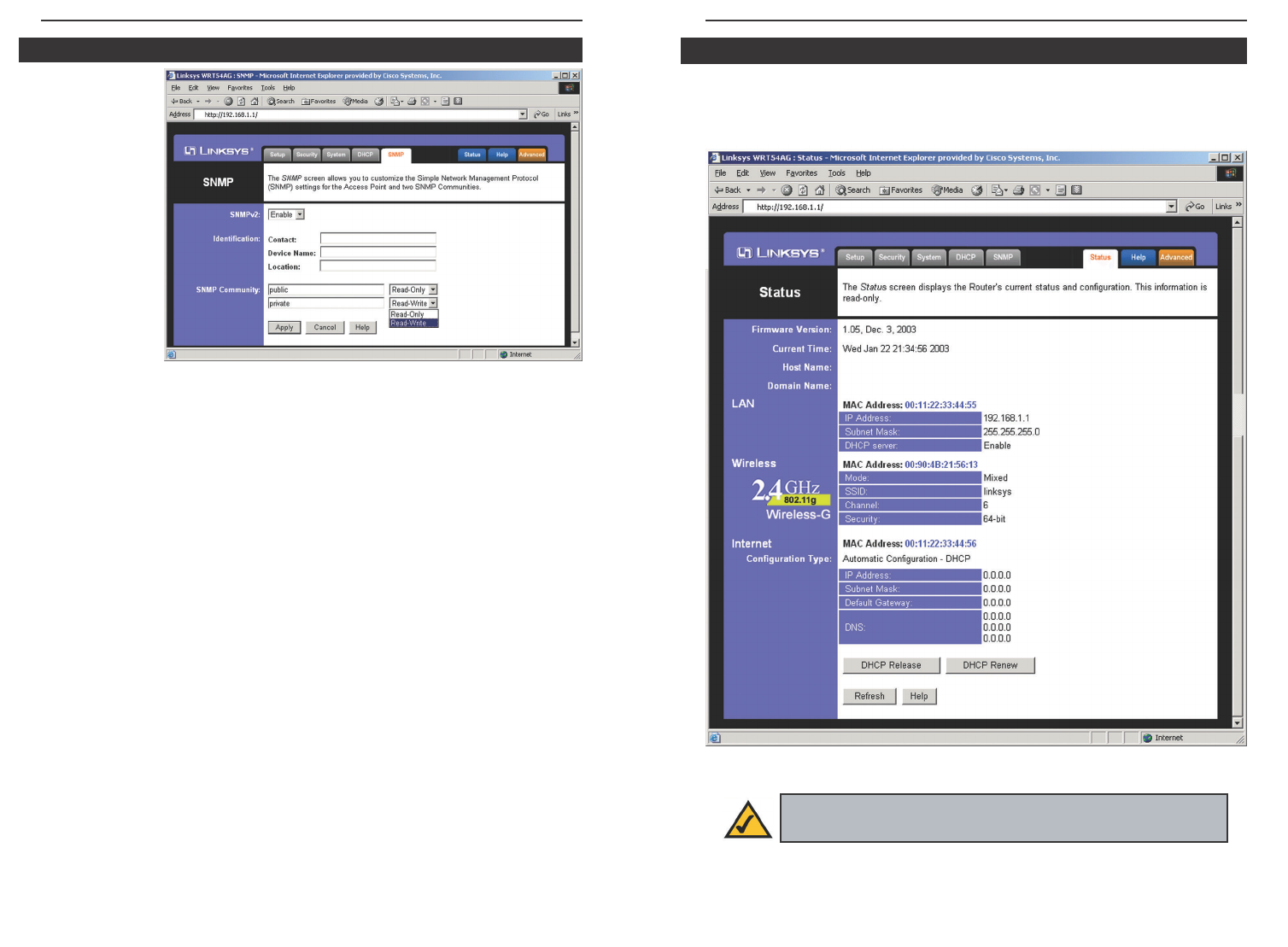
The SNMP tab,
shown in Figure
6-18, allows you
to customize the
Simple Network
Management
Protocol
(SNMP) set-
tings. SNMP is
a popular net-
work monitor-
ing and manage-
ment protocol.
The Identification settings let you designate the Contact, Device Name, and
Location information for the Router. The SNMP Community settings allow
names to be assigned to any SNMP communities that have been set up in the
network. You can define two different SNMP communities, with the default
names being Public and Private.
SNMPv2. To enable the SNMP support feature, select Enable.
Identification. In the Contact field, enter contact information for the Router.
In the Device Name field, enter the name of the Router. In the Location field,
specify the area or location where the Router resides.
SNMP Community. You may change the name from its default, Public. Enter
a new name in the Public field. Then configure the community's access as
either Read-Only or Read-Write.You may change the name from its default,
Private. Enter a new name in the Private field. Then configure the communi-
ty's access as either Read-Only or Read-Write.
When you’ve completed making any changes on this tab, click the Apply but-
ton to save those changes or Cancel to cancel your changes. For more infor-
mation on this tab, you can click the Help button.
46
SNMP
Figure 6-18

Dual-Band Wireless A/G Broadband Router
IP Address, Subnet Mask, and Default Gateway The Router’s IP Address,
Subnet Mask, and Default Gateway Address, as seen by external users on the
Internet, are displayed here.
DNS The DNS (Domain Name System) IP Addresses currently used by the
Router are shown here. Multiple DNS IP settings are common. In most cases,
the first available DNS entry is used.
DHCP Release Click the DHCP Release button to delete the Router’s current
Internet IP address.
DHCP Renew Click the DHCP Renew button to get a new Internet IP
address for the Router.
To update the Router’s status information, click the Refresh button. To get
more information about the features, click the Help button.
4948
Firmware Version The version number of the firmware currently installed is
displayed here.
Current Time The current date and time are displayed here.
Host Name The Host Name is the name of the Router. This entry is necessary
for some ISPs.
Domain Name The Domain Name is the name of the Router's domain. This
entry is necessary for some ISPs.
LAN
MAC Address The MAC Address of the LAN interface is displayed here.
IP Address and Subnet Mask The current IP Address and Subnet Mask of
the Router, as seen by users on your local area network (LAN), are displayed
here.
DHCP Server The status of the Router's DHCP server function is displayed
here.
Wireless 2.4GHz, 54g, Wireless-G
MAC Address The MAC Address of the wireless interface is displayed here.
Mode The Mode of the wireless network is displayed here.
SSID The SSID of the wireless network is displayed here.
Channel The Channel of the wireless network is displayed here.
Security The status of the WEP encryption is displayed here.
Internet
MAC Address The MAC Address of the Internet interface is displayed here.
Configuration Type The type of Internet connection is displayed here.
Dual-Band Wireless A/G Broadband Router
The following instructions are for advanced users or users whose setup needs
require special configuration. When you click the Advanced tab, you will be
able to set up these features. There are five additional tabs available.
Advanced Wireless - Allows you to customize data transmission settings for
your wireless network.
Internet Filter - Enables you to set up filters that block or allow specific kinds
of Internet usage.
Port Forwarding - Lets you set up public services on your network, such as an
ftp server, mail server, or web server.
Routing - Enables you to configure the routing mode and settings of the
Router.
If you need to access the basic configuration tabs, click the Setup tab.
51
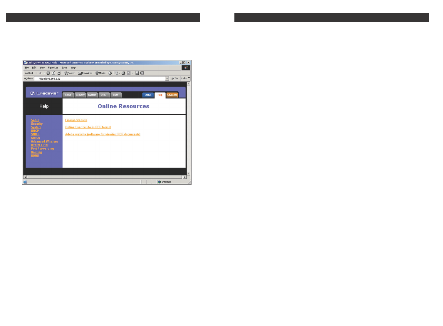
The Help screen, shown in Figure 6-20, offers links to all of the Router’s tech-
nical support resources and the application that upgrades the Router’s
firmware. For additional information about each screen of the web-based util-
ity, click the appropriate link on the lefthand side of the Help screen.
Linksys Website Clicking this link will take you to Linksys’s website,
www.linksys.com, provided you are connected to the Internet.
Online User Guide in PDF Format and Adobe Website Clicking the Online
User Guide in PDF format link opens the Router’s User Guide. The User
Guide is in Adobe Acrobat Portable Document File (.pdf) format, so you need
the Adobe Acrobat Reader to view it. If you do not have the Acrobat Reader,
click the Adobe website link to download it.
50
Advanced TabsHelp
Figure 6-20
Dual-Band Wireless A/G Broadband Router
Transmission Rate The rate of data transmission should be set depending on the
speed of your wireless network. You can select from a range of transmission speeds
(6, 9, 12, 18, 24, 36, 48, or 54Mbps), or you can select Auto to have the Router
automatically use the fastest possible data rate and enable the Auto-Fallback fea-
ture. Auto-Fallback will negotiate the best possible connection speed between the
Router and a wireless client. The default value is Auto.
Transmit Power Control (Wireless-G ONLY) The greater the transmit power
used, the larger the area a wireless network covers. To minimize the likelihood of
eavesdropping by unauthorized wireless users, do not use more transmit power than
necessary to cover the range needed for your wireless network. Try using the Router
at different levels of transmit power, and determine how much transmit power is
needed to reach the wireless client, such as a PC, or access point that is farthest
from the Router. Then select the appropriate level of transmit power (Full, Half,
Quarter, Eighth, or Min) from the drop-down menu. The default value is Full.
Beacon Interval The default value is 100. Enter a value between 1 and 65,535 mil-
liseconds. The Beacon Interval value indicates the frequency interval of the beacon.
A beacon is a packet broadcast by the Router to synchronize the wireless network.
DTIM Interval This value, between 1 and 16384, indicates the interval of the
Delivery Traffic Indication Message (DTIM). A DTIM field is a countdown field
informing clients of the next window for listening to broadcast and multicast mes-
sages. When the Router has buffered broadcast or multicast messages for associat-
ed clients, it sends the next DTIM with a DTIM Interval value. Its clients hear the
beacons and awaken to receive the broadcast and multicast messages. The default
value is 1.
RTS Threshold Should you encounter inconsistent data flow, only minor reduc-
tion of the default value, 2346, is recommended. If a network packet is smaller than
the preset RTS threshold size, the RTS/CTS mechanism will not be enabled. The
Router sends Request to Send (RTS) frames to a particular receiving station and
negotiates the sending of a data frame. After receiving an RTS, the wireless station
responds with a Clear to Send (CTS) frame to acknowledge the right to begin trans-
mission. The RTS Threshold value should remain at its default value of 2346.
Fragmentation Threshold This value specifies the maximum size for a packet
before data is fragmented into multiple packets. If you experience a high packet
error rate, you may slightly increase the Fragmentation Threshold. Setting the
Fragmentation Threshold too low may result in poor network performance. Only
minor reduction of the default value is recommended. In most cases, it should
remain at its default value of 2346.
53
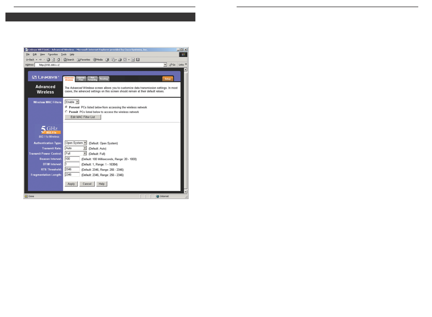
The Advanced Wireless screen, shown in Figure 6-21, allows you to customize
data transmission settings. In most cases, the advanced wireless settings on this
screen should remain at their default values.
Wireless MAC Filters Wireless access can be filtered by using the MAC
addresses of the wireless devices transmitting within your network’s radius.
Select Enable from the drop-down menu and choose if you wish to Prevent
wireless access by MAC address or Permit by MAC Address. Then, click the
Edit MAC Filter List button to access a secondary screen, where you can enter
the MAC Addresses of the devices you wish to filter.
Authentication Type The default is set to Auto, which allows either Open
System or Shared Key authentication to be used. For Open System authentica-
tion, the sender and the recipient do NOT use a WEP key for authentication.
For Shared Key authentication, the sender and recipient use a WEP key for
authentication. If you want to use only Shared Key authentication, then select
Shared Key.
52
Figure 6-21
Advanced Wireless
Dual-Band Wireless A/G Broadband Router
The summaries are
listed on this screen,
shown in Figure 6-23,
with their name and
settings. To delete any
summary from this
screen, check the
empty box beneath
Delete and then click
the Delete button. To
return to the Filters
tab, click the Close
button.
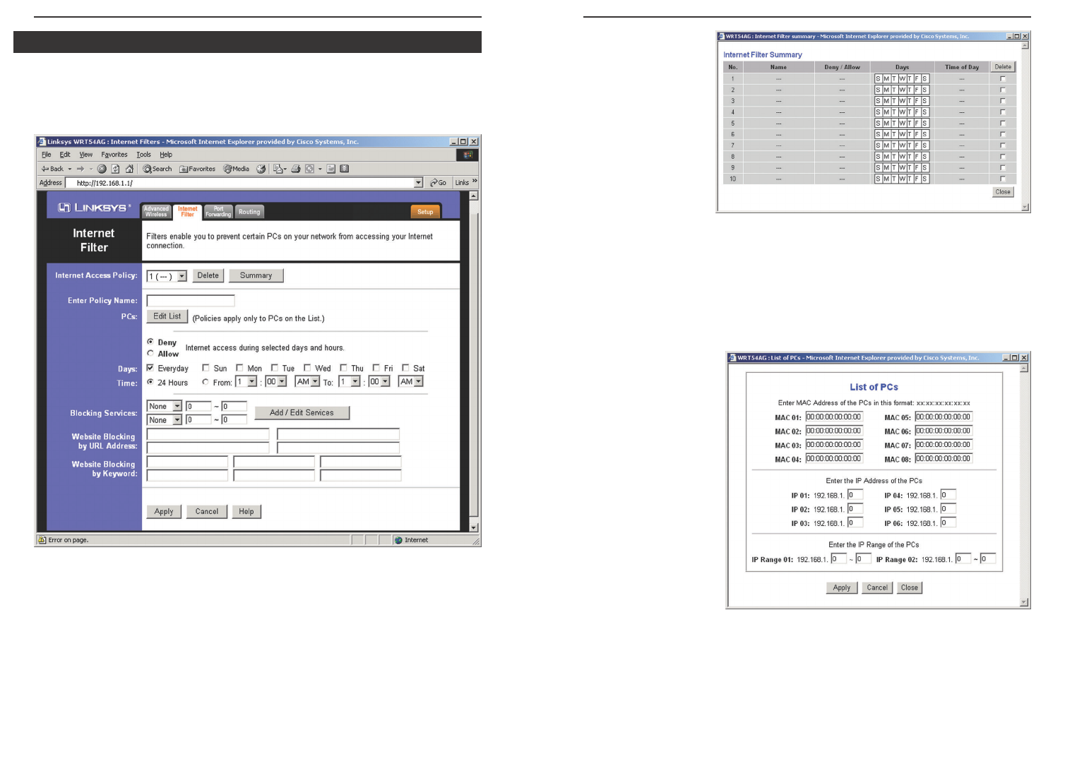
Enter Policy Name Policies are created from the fields presented here. To
create a policy:
1. Enter a Policy Name in the field provided.
2. Click the Edit List
of PCs button. This
will open the List of
PCs screen, shown
in Figure 6-24.
From this screen,
you can enter the IP
address or MAC
address of any PC
to which this policy
will apply. You can
even enter ranges of
PCs by IP address.
Click the Apply
button to save your
settings, the Cancel
button to undo any
changes, and the Close button to return to the Filters tab.
55
The Internet Filter tab, shown in Figure 6-22, allows you to block or allow spe-
cific kinds of Internet usage. You can set up Internet access policies for specif-
ic PCs and set up filters by using network port numbers.
Internet Access Policy Multiple Filters can be saved as Internet Access
Policies. When you wish to edit one, select the number of the Policy from the
drop-down menu. The tab will change to reflect the settings of this Policy. If
you wish to delete this Policy, click the Delete button.
To see a summary of all Policies, click the Summary button.
54
Figure 6-23
Internet Filter
Figure 6-22
Figure 6-24
Dual-Band Wireless A/G Broadband Router
57
The Port Forwarding screen (Figure 6-26) sets up public services on your net-
work, such as web servers, ftp servers, e-mail servers, or other specialized
Internet applications. (Specialized Internet applications are any applications
that use Internet access to perform functions such as videoconferencing or
online gaming. Some Internet applications may not require any forwarding.)
When users send this type of request to your network via the Internet, the
Router will forward those requests to the appropriate PC. Any PC whose port
is being forwarded must have its DHCP client function disabled and must have
a new static IP address assigned to it because its IP address may change when
using the DHCP function.
Port Forwarding
Figure 6-26
3. Select if you wish to Disable or Enable Internet access for those PCs you
listed on the List of PCs screen by clicking the radio button beside either
option.
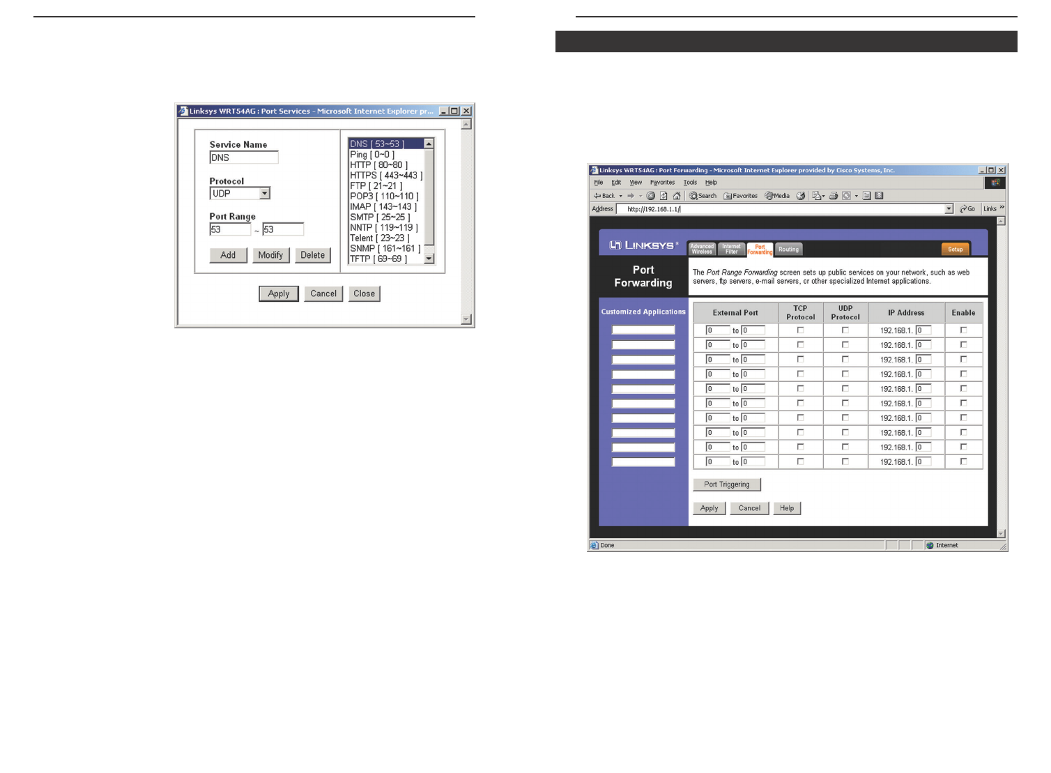
4. You can filter
access to various
services accessed
over the Internet,
such as FTP or
Telnet, by selecting
a service from the
pull-down menus
next to Services. If
a service isn’t listed,
you can click the
Add Service button
to open the Service
screen, shown in
Figure 6-25, and
add a service to the
list. You will need to enter a Service name, as well as the Protocol and Port
Range used by the service.
5. By selecting the appropriate setting next to Days and Time, choose when
Internet access will be filtered.
6. Lastly, click the Apply button to save and activate this policy.
Internet Access can also be filtered by URL Address, the address entered to
access Internet sites, by entering the address in one of the Website Blocking
by URL Address fields. If you do not know the URL Address, filtering can be
done by Keyword by entering a keyword in one of the Website Blocking by
Keyword fields.
To apply any of the settings you change on this page, click the Apply button. To
cancel any changes you’ve entered on this page, click the Cancel button. To get
more information about the features, click the Help button.
56
Figure 6-25
Dual-Band Wireless A/G Broadband Router
5958
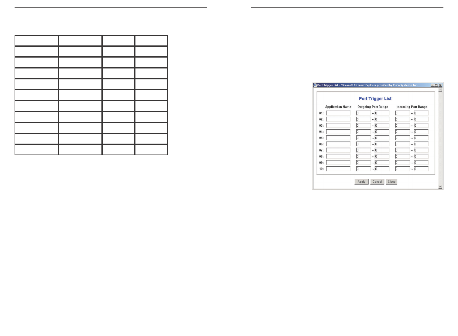
Port Triggering Port Triggering is used for special Internet applications whose
outgoing ports differ from the incoming ports. For this feature, the Router will
watch outgoing data for specific port numbers. The Router will remember the
IP address of the computer that sends a transmission requesting data, so that
when the requested data returns through the Router, the data is pulled back to
the proper computer by way of IP address and port mapping rules. Click the
Port Triggering button to set up triggered ports, and follow these instructions:
1. Enter the Application Name of the trigger (see Figure 6-27).
2. Enter the Outgoing
Port Range used by
the application.
Check with the
Internet application
for the port num-
ber(s) needed.
3. Enter the Incoming
Port Range used by
the application.
Check with the
Internet application
for the port num-
ber(s) needed.
4. Click the Apply button to save your changes. Click the Cancel button to
cancel your unsaved changes. Click the Close button to return to the Port
Forwarding screen.
To save your changes on this page, click the Apply button. To cancel any
unsaved changes on this page, click the Cancel button. To get more information
about the features, click the Help button.
Figure 6-27
The following table shows the typical port forwarding settings for common
Internet applications.
Customized Applications In the field provided, enter the name you wish to
give each application.
External Port For each application, enter the number of the External Ports
(the port numbers seen by users on the Internet) in the appropriate fields. (To
find out the port range, check your application's documentation.) If there is
only one External Port, enter its number in both External Port fields.
TCP Protocol Click this checkbox if you want to forward the data transmis-
sions that use the TCP protocol.
UDP Protocol Click this checkbox if you want to forward the data transmis-
sions that use the UDP protocol.
IP Address For each application, enter the IP Address of the PC running the
specific application.
Enable Click the Enable checkbox to enable port forwarding for the relevant
application.
Application
FTP
Telnet
SMTP
DNS
TFTP
Finger
HTTP
POP3
NNTP
SNMP
External Port
21
23
25
53
69
79
80
110
119
116
TCP
•
•
•
•
•
•
•
UDP
•
•
•
Dual-Band Wireless A/G Broadband Router
6160
4. To set up a static route between the Router and another network, select a
number from the Static Routing drop-down list. (A static route is a pre-
determined pathway that network information must travel to reach a spe-
cific host or network.)
5. Enter the following data:
• Destination LAN IP - The Destination LAN IP is the address of the
remote network or host to which you want to assign a static route.
• Subnet Mask - The Subnet Mask determines which portion of a
Destination LAN IP address is the network portion, and which portion
is the host portion.
• Gateway - This is the IP address of the gateway device that allows for
contact between the Router and the remote network or host.
•Interface - This interface tells you whether the Destination IP Address
is on the LAN & Wireless (internal wired and wireless networks), the
WA N (Internet), or Loopback (a dummy network in which one PC
acts like a network-necessary for certain software programs).
6. To cancel your changes, click the Cancel button. To save your changes,
click the Apply button. To get more information about the features, click
the Help button.
To delete a static route entry:
1. From the Static Routing drop-down list, select the entry number of the stat-
ic route.
2. Click the Delete This Entry button.
3. To cancel a deletion, click the Cancel button. To save a deletion, click the
Apply button. To get more information about the features, click the Help
button.
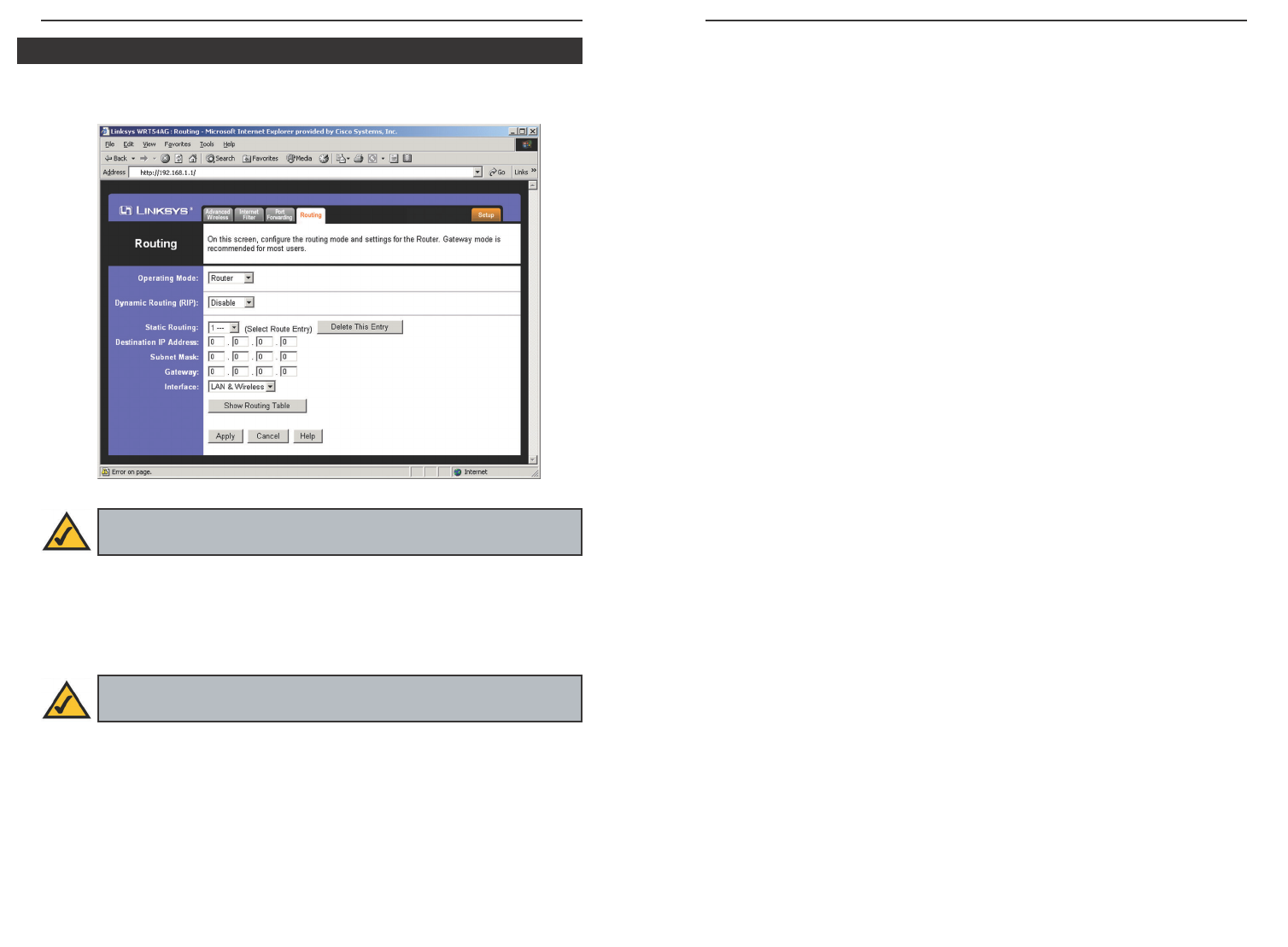
On the Routing screen, shown in Figure 6-28, you can set the routing mode of
the Router. Gateway mode is recommended for most users.
To set up routing:
1. Choose the correct working mode. Select Gateway if the Router is hosting
your network’s connection to the Internet (recommended for most users).
Select Router if the Router exists on a network with other routers.
2. If you selected the Gateway mode, click the Apply button. If you selected
the Router mode, proceed to step 3.
3. For Dynamic Routing, the default is Disable. The Dynamic Routing feature
enables the Router to automatically adjust to physical changes in the net-
work’s layout and exchange routing tables with the other router(s). The
Router determines the network packets’ route based on the fewest number
of hops between the source and the destination. Select Enable to enable the
Dynamic Routing feature for data transmissions.
Routing
Figure 6-28
Note: The Routing screen and available features will vary depending
on which mode you select.
Note: If you have more than one router on your network, you should
select Router for the working mode.