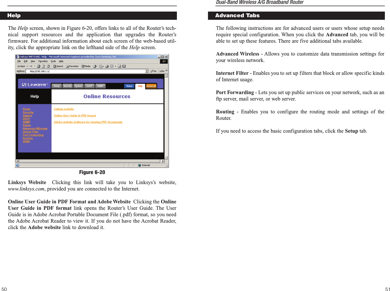
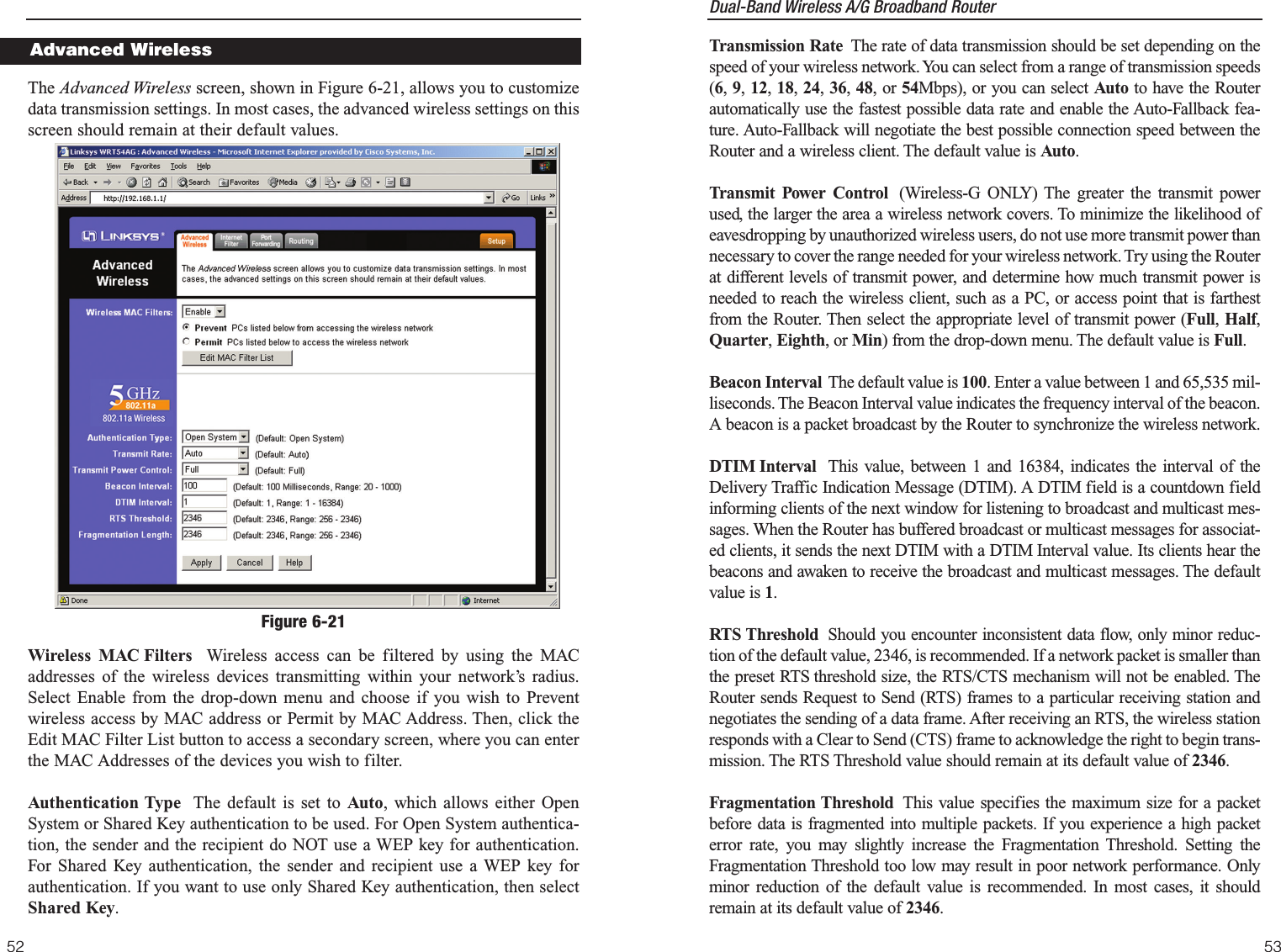
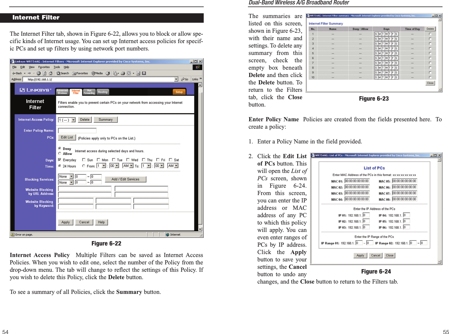
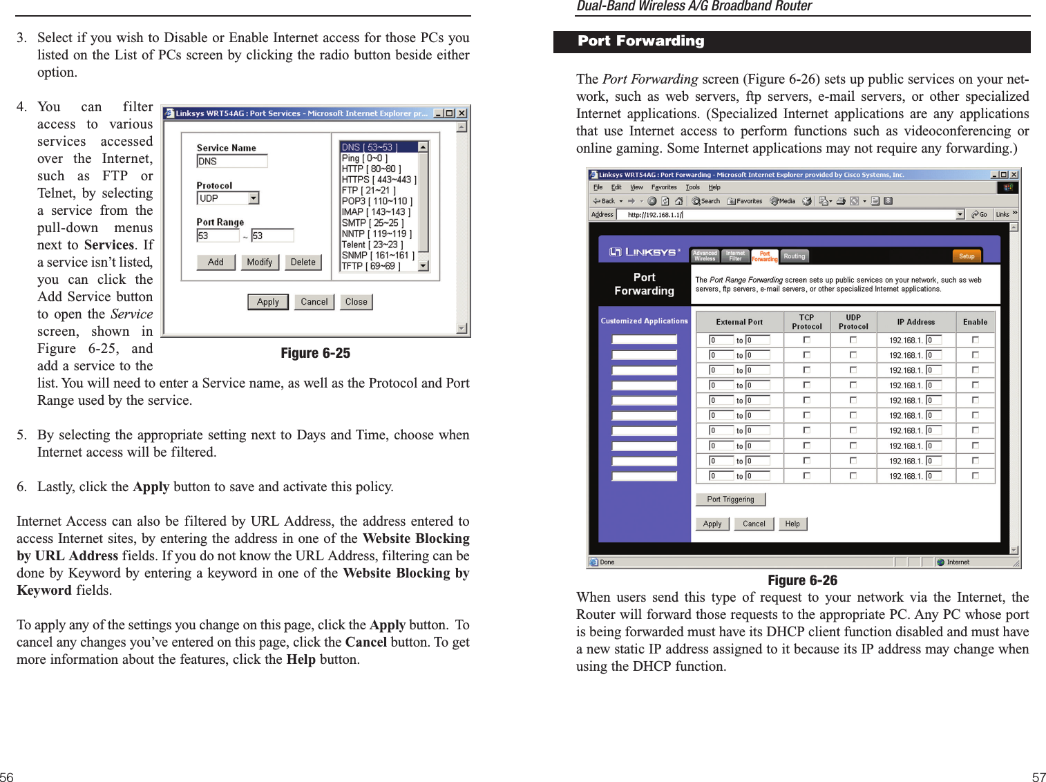
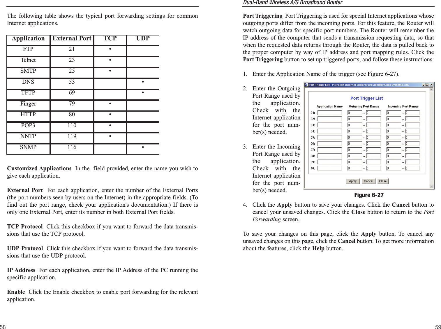
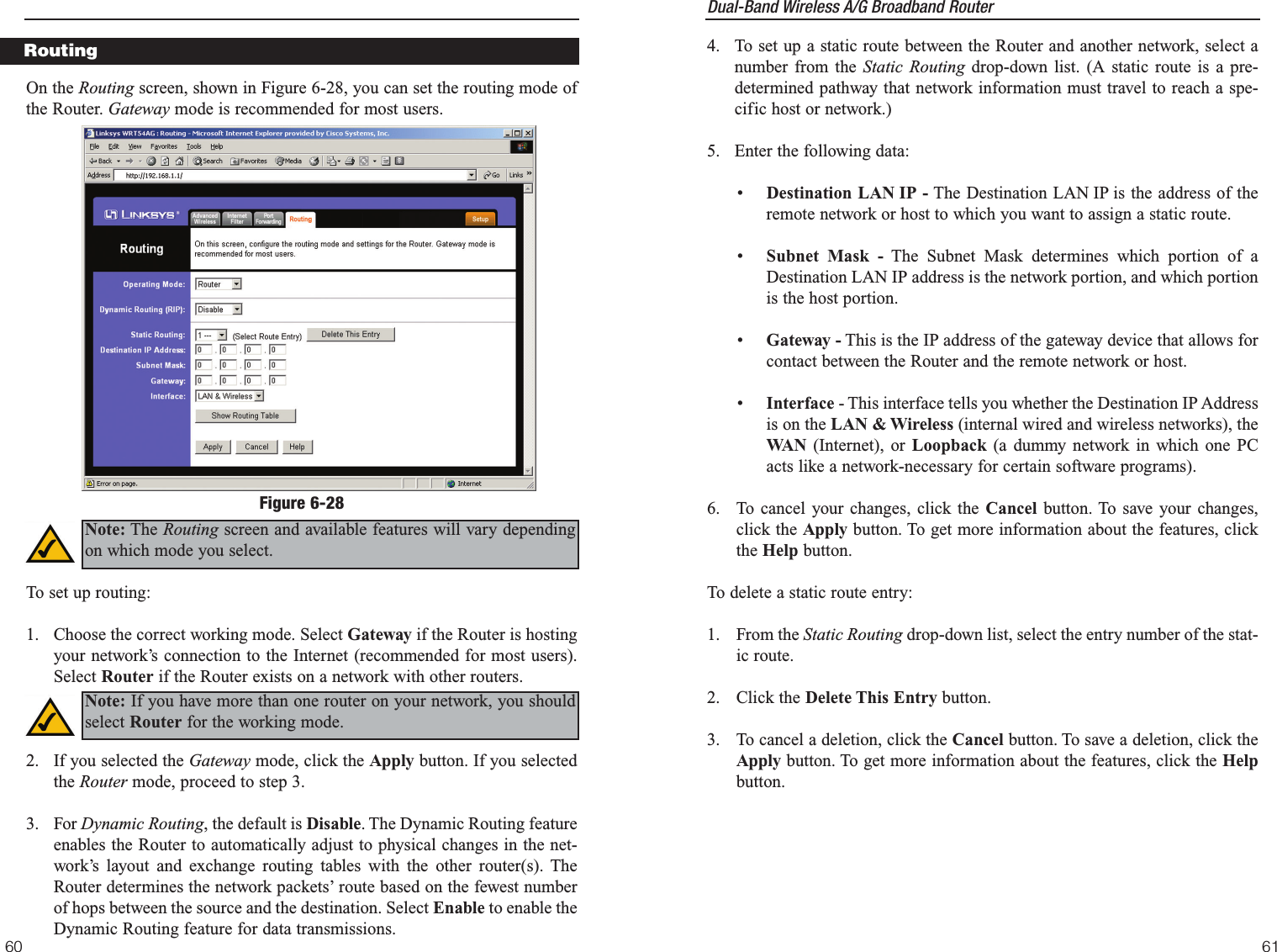
LINKSYS WRT54AG Wireless A/G Broadband Router User Manual WRT54AG ug Rev NC

LINKSYS LLC Wireless A/G Broadband Router WRT54AG ug Rev NC

Users Manual 3

Dual-Band Wireless A/G Broadband Router The Incoming Access Log gives you a log of all the incoming Internet traffic,displaying the Source IP address and Destination Port Number of the Routerfor each activity (see Figure 6-14). Click the Refresh button to update the logs.Click the Close button to return to the System screen.The Outgoing Access Log gives you a log of all outgoing Internet traffic. Foreach activity, it displays the LAN IP address, the Destination URL or IPaddress of the Internet site accessed, as well as the Service/Port Number used(see Figure 6-15). Click the Refresh button to update the logs. Click the Closebutton to return to the System screen.To save your changes on this page, click the Apply button. To cancel anyunsaved changes on this page, click the Cancel button. To get more informa-tion about the features, click the Help button.43To remotely manage the Router, enter http://xxx.xxx.xxx.xxx:8080 (the x’srepresent the Router's Internet IP address, and 8080 represents the specifiedport) in your web browser’s Address field. You will be asked for the Router’spassword. After successfully entering the password, you will be able to accessthe Router’s web-based utility.MTU  MTU is the Maximum Transmission Unit. It specifies the largest pack-et size permitted for Internet transmission. Keep the default setting, Auto, tohave the Router select the best MTU for your Internet connection. To specify aMTU size, select Manual, and enter the value desired (default is 1400).  Youshould leave this value in the 1200 to 1500 range.Log  The Router can keep logs of all traffic for your Internet connection. Todisable the Log function, keep the default setting, Disable. To monitor trafficbetween the network and the Internet, select Enable. Send Log To  Enter the IP Address of the PC where you would like the Logssent.Temporary logs can be accessed by clicking either the Incoming Access Logor Outgoing Access Log button.42Note: If the Remote Management feature is enabled, anyone whoknows the Router’s Internet IP address and password will be able toalter the Router’s settings.Figure 6-14Figure 6-15
Dual-Band Wireless A/G Broadband Router 4544Maximum Number of DHCP Users (Optional) Enter the maximum numberof PCs that you want the DHCP server to assign IP addresses to. This numbercannot be greater than 253. The default is 50.Client Lease Time The Client Lease Time is the amount of time a networkuser will be allowed connection to the Router with their current dynamic IPaddress. Enter the amount of time, in minutes, that the user will be “leased” thisdynamic IP address. After the time is up, the user will be automaticallyassigned a new dynamic IP address. The default is 0minutes, which means oneday.Static DNS 1-3 The Domain Name System (DNS) is how the Internet trans-lates domain or website names into Internet addresses or URLs. Your ISP willprovide you with at least one DNS Server IP Address. If you wish to use anoth-er, type that IP Address in one of these fields. You can type up to three DNSServer IP Addresses here. The Router will use these for quicker access to func-tioning DNS servers.WINS The Windows Internet Naming Service (WINS) manages each PC’sinteraction with the Internet. If you use a WINS server, enter that server’s IPAddress here. Otherwise, leave this blank.Currently Assigned: DHCP Clients Table  Click the DHCP Clients Tablebutton to view the list of PCs that are given IP addresses by the Router (seeFigure 6-17). For each PC, the list shows the Client Hostname, IP Address,MAC Address, and and the amount of DHCP client lease time left. Click theRefresh button to display the most current information. To save your changes on this page, click the Apply button. To cancel anyunsaved changes on this page, click the Cancel button. To get more informationabout the features, click the Help button.Figure 6-17The DHCP screen, shown in Figure 6-16, allows you to configure the settingsfor the Router’s Dynamic Host Configuration Protocol (DHCP) server func-tion. The Router can be used as a DHCP server for your network. A DHCPserver automatically assigns an IP address to each computer on your network. If you choose to enable the Router’s DHCP server option, you must configureall of your network PCs to connect to a DHCP server (the Router), and makesure there is no other DHCP server on your network. DHCP Server  DHCP is enabled by factory default. If you already have aDHCP server on your network, or you don’t want a DHCP server, then click theDisable radio button (no other DHCP features will be available).Starting IP Address Enter a value for the DHCP server to start with whenissuing IP addresses.  Because the Router’s default IP address is 192.168.1.1,the Starting IP Address must be 192.168.1.2 or greater, but smaller than192.168.1.253. The default Starting IP Address is 192.168.1.100.DHCPFigure 6-16
Dual-Band Wireless A/G Broadband Router 47The Status screen, shown in Figure 6-19, displays the Router’s current statusand configuration. All information is read-only.StatusFigure 6-19Note: The information provided and buttons available may varydepending on the Router’s settings. The  SNMP tab,shown in Figure6-18, allows youto customize theSimple NetworkManagementProtocol(SNMP) set-tings. SNMP isa popular net-work monitor-ing and manage-ment protocol. The Identification settings let you designate the Contact, Device Name, andLocation information for the Router. The SNMP Community settings allownames to be assigned to any SNMP communities that have been set up in thenetwork. You can define two different SNMP communities, with the defaultnames being Public and Private.SNMPv2. To enable the SNMP support feature, select Enable.Identification. In the Contact field, enter contact information for the Router.In the Device Name field, enter the name of the Router. In the Location field,specify the area or location where the Router resides.SNMP Community. You may change the name from its default, Public. Entera new name in the Public field. Then configure the community's access aseither Read-Only or Read-Write.You may change the name from its default,Private. Enter a new name in the Private field. Then configure the communi-ty's access as either Read-Only or Read-Write.When you’ve completed making any changes on this tab, click the Apply but-ton to save those changes or Cancel to cancel your changes. For more infor-mation on this tab, you can click the Help button.46SNMPFigure 6-18
Dual-Band Wireless A/G Broadband Router IP Address, Subnet Mask, and Default Gateway  The Router’s IP Address,Subnet Mask, and Default Gateway Address, as seen by external users on theInternet, are displayed here.DNS The DNS (Domain Name System) IP Addresses currently used by theRouter are shown here. Multiple DNS IP settings are common. In most cases,the first available DNS entry is used.DHCP Release  Click the DHCP Release button to delete the Router’s currentInternet IP address. DHCP Renew  Click the DHCP Renew button to get a new Internet IPaddress for the Router. To update the Router’s status information, click the Refresh button. To getmore information about the features, click the Help button.4948Firmware Version The version number of the firmware currently installed isdisplayed here.Current Time The current date and time are displayed here.Host Name The Host Name is the name of the Router. This entry is necessaryfor some ISPs.Domain Name  The Domain Name is the name of the Router's domain. Thisentry is necessary for some ISPs.LANMAC Address  The MAC Address of the LAN interface is displayed here.IP Address and Subnet Mask The current IP Address and Subnet Mask ofthe Router, as seen by users on your local area network (LAN), are displayedhere. DHCP Server  The status of the Router's DHCP server function is displayedhere.Wireless 2.4GHz, 54g, Wireless-GMAC Address The MAC Address of the wireless interface is displayed here.Mode The Mode of the wireless network is displayed here. SSID The SSID of the wireless network is displayed here.Channel The Channel of the wireless network is displayed here.Security The status of the WEP encryption is displayed here.InternetMAC Address  The MAC Address of the Internet interface is displayed here.Configuration Type  The type of Internet connection is displayed here.
Dual-Band Wireless A/G Broadband Router The following instructions are for advanced users or users whose setup needsrequire special configuration. When you click the Advanced tab, you will beable to set up these features. There are five additional tabs available. Advanced Wireless - Allows you to customize data transmission settings foryour wireless network.Internet Filter - Enables you to set up filters that block or allow specific kindsof Internet usage.Port Forwarding - Lets you set up public services on your network, such as anftp server, mail server, or web server.Routing - Enables you to configure the routing mode and settings of theRouter.If you need to access the basic configuration tabs, click the Setup tab. 51The Help screen, shown in Figure 6-20, offers links to all of the Router’s tech-nical support resources and the application that upgrades the Router’sfirmware. For additional information about each screen of the web-based util-ity, click the appropriate link on the lefthand side of the Help screen.Linksys Website Clicking this link will take you to Linksys’s website,www.linksys.com, provided you are connected to the Internet. Online User Guide in PDF Format and Adobe Website Clicking the OnlineUser Guide in PDF format link opens the Router’s User Guide. The UserGuide is in Adobe Acrobat Portable Document File (.pdf) format, so you needthe Adobe Acrobat Reader to view it. If you do not have the Acrobat Reader,click the Adobe website link to download it.50Advanced TabsHelpFigure 6-20
Dual-Band Wireless A/G Broadband Router Transmission Rate The rate of data transmission should be set depending on thespeed of your wireless network. You can select from a range of transmission speeds(6, 9, 12, 18, 24, 36, 48, or 54Mbps), or you can select Auto to have the Routerautomatically use the fastest possible data rate and enable the Auto-Fallback fea-ture. Auto-Fallback will negotiate the best possible connection speed between theRouter and a wireless client. The default value is Auto.Transmit Power Control (Wireless-G ONLY) The greater the transmit powerused, the larger the area a wireless network covers. To minimize the likelihood ofeavesdropping by unauthorized wireless users, do not use more transmit power thannecessary to cover the range needed for your wireless network. Try using the Routerat different levels of transmit power, and determine how much transmit power isneeded to reach the wireless client, such as a PC, or access point that is farthestfrom the Router. Then select the appropriate level of transmit power (Full, Half,Quarter, Eighth, or Min) from the drop-down menu. The default value is Full.Beacon Interval The default value is 100. Enter a value between 1 and 65,535 mil-liseconds. The Beacon Interval value indicates the frequency interval of the beacon.A beacon is a packet broadcast by the Router to synchronize the wireless network.DTIM Interval This value, between 1 and 16384, indicates the interval of theDelivery Traffic Indication Message (DTIM). A DTIM field is a countdown fieldinforming clients of the next window for listening to broadcast and multicast mes-sages. When the Router has buffered broadcast or multicast messages for associat-ed clients, it sends the next DTIM with a DTIM Interval value. Its clients hear thebeacons and awaken to receive the broadcast and multicast messages. The defaultvalue is 1.RTS Threshold Should you encounter inconsistent data flow, only minor reduc-tion of the default value, 2346, is recommended. If a network packet is smaller thanthe preset RTS threshold size, the RTS/CTS mechanism will not be enabled. TheRouter sends Request to Send (RTS) frames to a particular receiving station andnegotiates the sending of a data frame. After receiving an RTS, the wireless stationresponds with a Clear to Send (CTS) frame to acknowledge the right to begin trans-mission. The RTS Threshold value should remain at its default value of 2346. Fragmentation Threshold This value specifies the maximum size for a packetbefore data is fragmented into multiple packets. If you experience a high packeterror rate, you may slightly increase the Fragmentation Threshold. Setting theFragmentation Threshold too low may result in poor network performance. Onlyminor reduction of the default value is recommended. In most cases, it shouldremain at its default value of 2346.53The Advanced Wireless screen, shown in Figure 6-21, allows you to customizedata transmission settings. In most cases, the advanced wireless settings on thisscreen should remain at their default values.Wireless MAC Filters Wireless access can be filtered by using the MACaddresses of the wireless devices transmitting within your network’s radius.Select Enable from the drop-down menu and choose if you wish to Preventwireless access by MAC address or Permit by MAC Address. Then, click theEdit MAC Filter List button to access a secondary screen, where you can enterthe MAC Addresses of the devices you wish to filter.Authentication Type The default is set to Auto, which allows either OpenSystem or Shared Key authentication to be used. For Open System authentica-tion, the sender and the recipient do NOT use a WEP key for authentication.For Shared Key authentication, the sender and recipient use a WEP key forauthentication. If you want to use only Shared Key authentication, then selectShared Key. 52Figure 6-21Advanced Wireless
Dual-Band Wireless A/G Broadband Router The summaries arelisted on this screen,shown in Figure 6-23,with their name andsettings. To delete anysummary from thisscreen, check theempty box beneathDelete and then clickthe Delete button. Toreturn to the Filterstab, click the Closebutton.Enter Policy Name Policies are created from the fields presented here.  Tocreate a policy:1. Enter a Policy Name in the field provided.2. Click the Edit Listof PCs button. Thiswill open the List ofPCs screen, shownin Figure 6-24.From this screen,you can enter the IPaddress or MACaddress of any PCto which this policywill apply. You caneven enter ranges ofPCs by IP address.Click the Applybutton to save yoursettings, the Cancelbutton to undo anychanges, and the Close button to return to the Filters tab.55The Internet Filter tab, shown in Figure 6-22, allows you to block or allow spe-cific kinds of Internet usage. You can set up Internet access policies for specif-ic PCs and set up filters by using network port numbers.Internet Access Policy Multiple Filters can be saved as Internet AccessPolicies. When you wish to edit one, select the number of the Policy from thedrop-down menu. The tab will change to reflect the settings of this Policy. Ifyou wish to delete this Policy, click the Delete button.To see a summary of all Policies, click the Summary button.54Figure 6-23Internet FilterFigure 6-22Figure 6-24
Dual-Band Wireless A/G Broadband Router 57The Port Forwarding screen (Figure 6-26) sets up public services on your net-work, such as web servers, ftp servers, e-mail servers, or other specializedInternet applications. (Specialized Internet applications are any applicationsthat use Internet access to perform functions such as videoconferencing oronline gaming. Some Internet applications may not require any forwarding.)When users send this type of request to your network via the Internet, theRouter will forward those requests to the appropriate PC. Any PC whose portis being forwarded must have its DHCP client function disabled and must havea new static IP address assigned to it because its IP address may change whenusing the DHCP function.Port ForwardingFigure 6-263. Select if you wish to Disable or Enable Internet access for those PCs youlisted on the List of PCs screen by clicking the radio button beside eitheroption.4. You can filteraccess to variousservices accessedover the Internet,such as FTP orTelnet, by selectinga service from thepull-down menusnext to Services. Ifa service isn’t listed,you can click theAdd Service buttonto open the Servicescreen, shown inFigure 6-25, andadd a service to thelist. You will need to enter a Service name, as well as the Protocol and PortRange used by the service.5. By selecting the appropriate setting next to Days and Time, choose whenInternet access will be filtered.6. Lastly, click the Apply button to save and activate this policy.Internet Access can also be filtered by URL Address, the address entered toaccess Internet sites, by entering the address in one of the Website Blockingby URL Address fields. If you do not know the URL Address, filtering can bedone by Keyword by entering a keyword in one of the Website Blocking byKeyword fields.To apply any of the settings you change on this page, click the Apply button.  Tocancel any changes you’ve entered on this page, click the Cancel button. To getmore information about the features, click the Help button.56Figure 6-25
Dual-Band Wireless A/G Broadband Router 5958Port Triggering Port Triggering is used for special Internet applications whoseoutgoing ports differ from the incoming ports. For this feature, the Router willwatch outgoing data for specific port numbers. The Router will remember theIP address of the computer that sends a transmission requesting data, so thatwhen the requested data returns through the Router, the data is pulled back tothe proper computer by way of IP address and port mapping rules. Click thePort Triggering button to set up triggered ports, and follow these instructions:1.  Enter the Application Name of the trigger (see Figure 6-27).2.  Enter the OutgoingPort Range used bythe application.Check with theInternet applicationfor the port num-ber(s) needed.3. Enter the IncomingPort Range used bythe application.Check with theInternet applicationfor the port num-ber(s) needed.4. Click the Apply button to save your changes. Click the Cancel button tocancel your unsaved changes. Click the Close button to return to the PortForwarding screen.To save your changes on this page, click the Apply button. To cancel anyunsaved changes on this page, click the Cancel button. To get more informationabout the features, click the Help button.Figure 6-27The following table shows the typical port forwarding settings for commonInternet applications. Customized Applications In the  field provided, enter the name you wish togive each application.External Port For each application, enter the number of the External Ports(the port numbers seen by users on the Internet) in the appropriate fields. (Tofind out the port range, check your application's documentation.) If there isonly one External Port, enter its number in both External Port fields.TCP Protocol Click this checkbox if you want to forward the data transmis-sions that use the TCP protocol.UDP Protocol  Click this checkbox if you want to forward the data transmis-sions that use the UDP protocol.IP Address For each application, enter the IP Address of the PC running thespecific application.Enable Click the Enable checkbox to enable port forwarding for the relevantapplication.ApplicationFTPTelnetSMTPDNSTFTPFingerHTTPPOP3NNTPSNMPExternal Port21232553697980110119116TCP•••••••UDP•••
Dual-Band Wireless A/G Broadband Router 61604.  To set up a static route between the Router and another network, select anumber from the Static Routing drop-down list. (A static route is a pre-determined pathway that network information must travel to reach a spe-cific host or network.)5.  Enter the following data:•  Destination LAN IP - The Destination LAN IP is the address of theremote network or host to which you want to assign a static route.•  Subnet Mask - The Subnet Mask determines which portion of aDestination LAN IP address is the network portion, and which portionis the host portion. •  Gateway - This is the IP address of the gateway device that allows forcontact between the Router and the remote network or host.•Interface - This interface tells you whether the Destination IP Addressis on the LAN & Wireless (internal wired and wireless networks), theWA N (Internet), or Loopback (a dummy network in which one PCacts like a network-necessary for certain software programs). 6.  To cancel your changes, click the Cancel button. To save your changes,click the Apply button. To get more information about the features, clickthe Help button.To delete a static route entry:1. From the Static Routing drop-down list, select the entry number of the stat-ic route.2. Click the Delete This Entry button.3.  To cancel a deletion, click the Cancel button. To save a deletion, click theApply button. To get more information about the features, click the Helpbutton.On the Routing screen, shown in Figure 6-28, you can set the routing mode ofthe Router. Gateway mode is recommended for most users. To set up routing:1.  Choose the correct working mode. Select Gateway if the Router is hostingyour network’s connection to the Internet (recommended for most users).Select Router if the Router exists on a network with other routers.2.  If you selected the Gateway mode, click the Apply button. If you selectedthe Router mode, proceed to step 3.3. For Dynamic Routing, the default is Disable. The Dynamic Routing featureenables the Router to automatically adjust to physical changes in the net-work’s layout and exchange routing tables with the other router(s). TheRouter determines the network packets’ route based on the fewest numberof hops between the source and the destination. Select Enable to enable theDynamic Routing feature for data transmissions.RoutingFigure 6-28Note: The Routing screen and available features will vary dependingon which mode you select.Note: If you have more than one router on your network, you shouldselect Router for the working mode.

Navigation menu