Leidos 418M1 RTR-4 Wireless Option User Manual RTR 4 WSCover
Science Application International Corporation RTR-4 Wireless Option RTR 4 WSCover
Leidos >
Contents
11 through 17
RTR-4 Portable Digital X-Ray Imaging System--Operator’s Manual Supplement
3-2 SAIC Proprietary 306847 Rev A
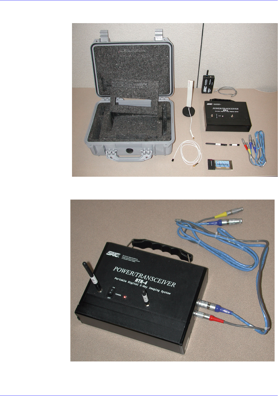
Figure 3-1: RTR-4 Wireless Option Items
Figure 3-2: Power/Transceiver Unit
1
23
4
5
67 8
9

RTR-4 Portable Digital X-Ray Imaging System--Operator’s Manual Supplement
306847 Rev A SAIC Proprietary 3-3
The Power/Transceiver unit (Figure 3-2) has three functions:
•Provides power to the imager previously supplied by the
controller (in the CU-4 case) or the external power supply
(in the notebook case).
•Facilitates wireless communication between the controller
and the imager.
•Sends the wireless signal from the imager to the x-ray
source for firing x-rays.
The Power/Transceiver unit has five assemblies:
•The black chassis
•Antenna 1 (tall, transceiving antenna)
•Antenna 2 (short, transmitting antenna)
•The blue Power/Transceiver-to-Imager cable for
controller-and-imager communications
•The gray Power/Transceiver-to-Imager cable for
imager-to-x-ray-source communications
The chassis houses all the active components, the battery, the
imager-to-controller transceiver, and the x-ray transmitter.
Antenna 1 provides signals for communication with the
controller; Antenna 2 provides signals to the X-ray Receiver. The
blue cable provides communication to the imager, and the gray
cable (with one red strain relief and one yellow) provides
communication from the imager for x-ray firing purposes.
The Power/Transceiver has a convenient briefcase-style handle
and contains a 10.8-Volt smart battery that is the same type as
provided with the CU-4 controllers. This battery can be
recharged using either the single-slot or the dual-slot charger
sometimes rovided with the RTR-4 controllers, or in the RTR-4
CU-4 controller's battery compartment. The Power/Transceiver
also has a power switch and a power-indication LED as shown in
Figure 3-2. The battery is in use whenever the power switch is on
and the LED is illuminated. (Early versions have a red LED; later
versions have a green LED.)
Radio-frequency communications between the Imager and the
Controller combined with the radio-frequency communications
with the X-ray Receiver are very low intensity. When the
Power/Transceiver is more than 50 cm (1.5 feet) away from a
target device, then the RTR-4 Wireless Option complies with the
HERO specifications. (If the RTR-4 is not being used with
potentially-explosive devices, then this specification is
irrelevant.)

RTR-4 Portable Digital X-Ray Imaging System--Operator’s Manual Supplement
3-4 SAIC Proprietary 306847 Rev A
The transmission frequency of the Power/Transceiver when
communicating with the imager is near 2.4 GHz. This
communication is done between 2.4000 and 2.4835 GHz, is
spread-spectrum and frequency-hopping, according to the
IEEE-802.11b-1999 standard, and is further encrypted to
minimize snooping or spoofing. The frequency used when
transmitting to the X-ray Receiver is about 418 MHz, is very low
power and is coded with a sequencing 64-bit security code to
minimize the possibility of unintended source firing. Battery
replacement procedures are described in Chapter 6.
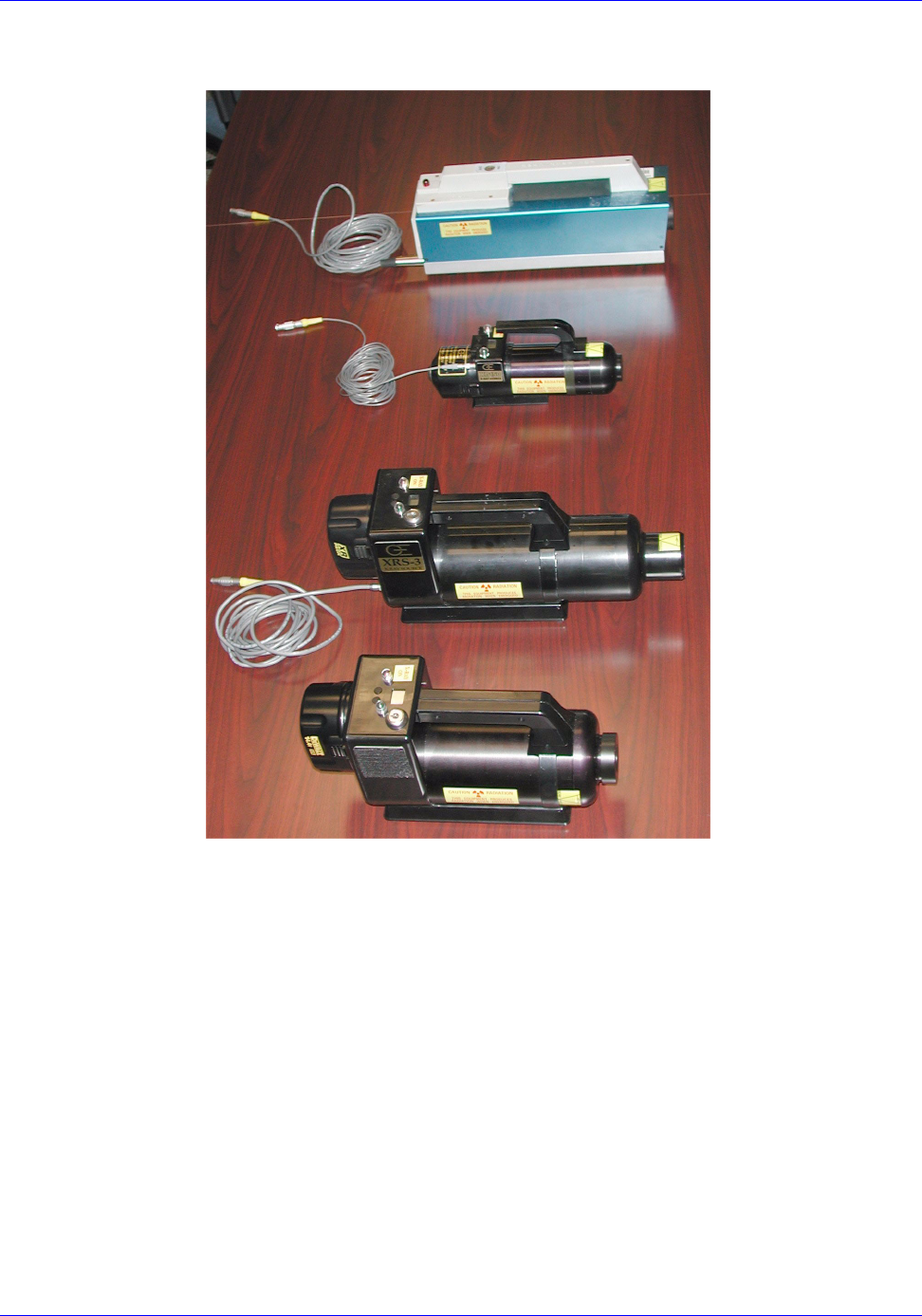
X-ray Receiver Unit
The X-ray Receiver unit (Figure 3-3) receives a signal from the
Power/Transceiver and fires the x-ray source. It has two
components, the body and the cable. The detachable cable can
accommodate any of the four x-ray sources manufactured by
Golden Engineering. They are listed below in order of their
appearance from top to bottom in Figure 3-4:
• Inspector Model 200 (special cable)
• XR-150 (special cable)
• XRS-3 (standard cable)
• XR-200 (standard cable)
The Inspector Model 200 was discontinued by Golden
Engineering in 1998, but the RTR-4 Wireless Option still
supports it.
The X-ray Receiver unit is powered by a standard 9-volt alkaline
battery and has a power switch with an indicating LED. Battery
replacement procedures are described in Chapter 6.
Figure 3-3: X-Ray Receiver Unit
RTR-4 Portable Digital X-Ray Imaging System--Operator’s Manual Supplement
306847 Rev A SAIC Proprietary 3-5
Figure 3-4: Four Golden Engineering X-ray Source Units

RTR-4 Portable Digital X-Ray Imaging System--Operator’s Manual Supplement
3-6 SAIC Proprietary 306847 Rev A

306847 Rev A SAIC Proprietary 4-1
4 Wireless Option Setup
Introduction
This chapter describes the tasks uniquely required to prepare the
RTR-4 Wireless Option for operation to be described in Chapter 5.
Routine RTR-4 physical setup procedures are described in
Chapter 2 of the RTR-4 Operator’s Manual except for the Wireless
Option Setup tasks described here.
The wireless option setup tasks in their proper sequence are:
• Power Transceiver Setup
• X-ray Receiver Setup
• WiFi NIC Setup
• Optional Medium-Range Antenna Setup
• System Initialization
• Wireless Connection Test
Power/Transceiver Setup
Connecting the Power/Transceiver
Connecting the Power/Transceiver Description
The Power Transceiver must be connected to the XR200 X-Ray
source and Imager order for the XR200 and Imager to transceive
commands with the controller.
Prerequisites
None.
Connecting the Power/Transceiver
The Power Transceiver is connected to the XR200 and Imager as
follows
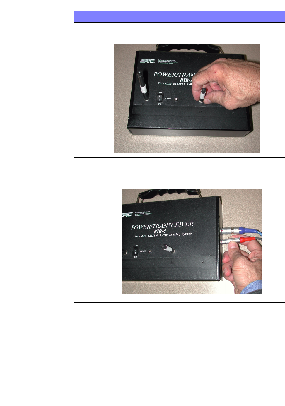
STEP ACTION
1Remove the Power Transceiver (Figure 3-2) from its packing
case and place it on a flat, solid surface as close as possible
to the XR200 and Imager.
RTR-4 Portable Digital X-Ray Imaging System--Operator’s Manual Supplement
4-2 SAIC Proprietary 306847 Rev A
2Screw on the two antennas (one shorter, one taller) to the
Power/Transceiver as shown below:
3Insert one end of the Power/Transceiver’s “X-Ray” coaxial
cable into the red-labeled “X-Ray” jack on the right-hand end
of the Power Transceiver as shown below.
STEP ACTION