Leidos 418M1 RTR-4 Wireless Option User Manual RTR 4 WSCover
Science Application International Corporation RTR-4 Wireless Option RTR 4 WSCover
Leidos >
Contents
18 throug 21
RTR-4 Portable Digital X-Ray Imaging System--Operator’s Manual Supplement
306847 Rev A SAIC Proprietary 4-3
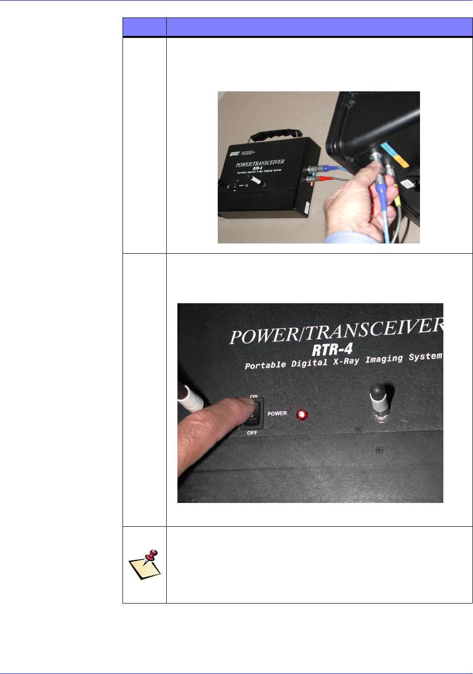
3Insert one end of the Power/Transceiver’s “Imager” coaxial
cable into the blue labeled “Imager” jack on the right-hand
end of the Power/Transceiver and the other to the
appropriate jack on the Imager.
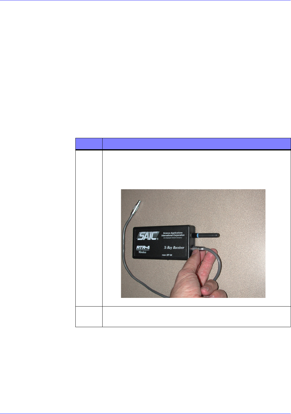
4Power up the Power/Transceiver by pressing its On/Off
rocker switch to the On position as shown below. The red
“POWER” LED to the right of the switch should illuminate.
NOTE
If the “POWER” LED fails to illuminate, replace the Power/
Transceiver battery in accordance with the procedure in
Chapter 6. If it still fails to illuminate, replace the
Power/Transceiver.
STEP ACTION
RTR-4 Portable Digital X-Ray Imaging System--Operator’s Manual Supplement
4-4 SAIC Proprietary 306847 Rev A
X-ray Receiver Setup
Connecting the X-ray Receiver
X-ray Receiver Connection Description
The X-ray Receiver must be Velcro-mounted on the XR200 X-Ray
source and its cable connected to the source in order for the XR200
to transceive commands to and from the Power/Transceiver.
Prerequisites
The Connecting the Power/Transceiver procedure must have
been completed.
Connecting the X-ray Receiver
The X-ray Receiver is connected to the XR200 as follows
STEP ACTION
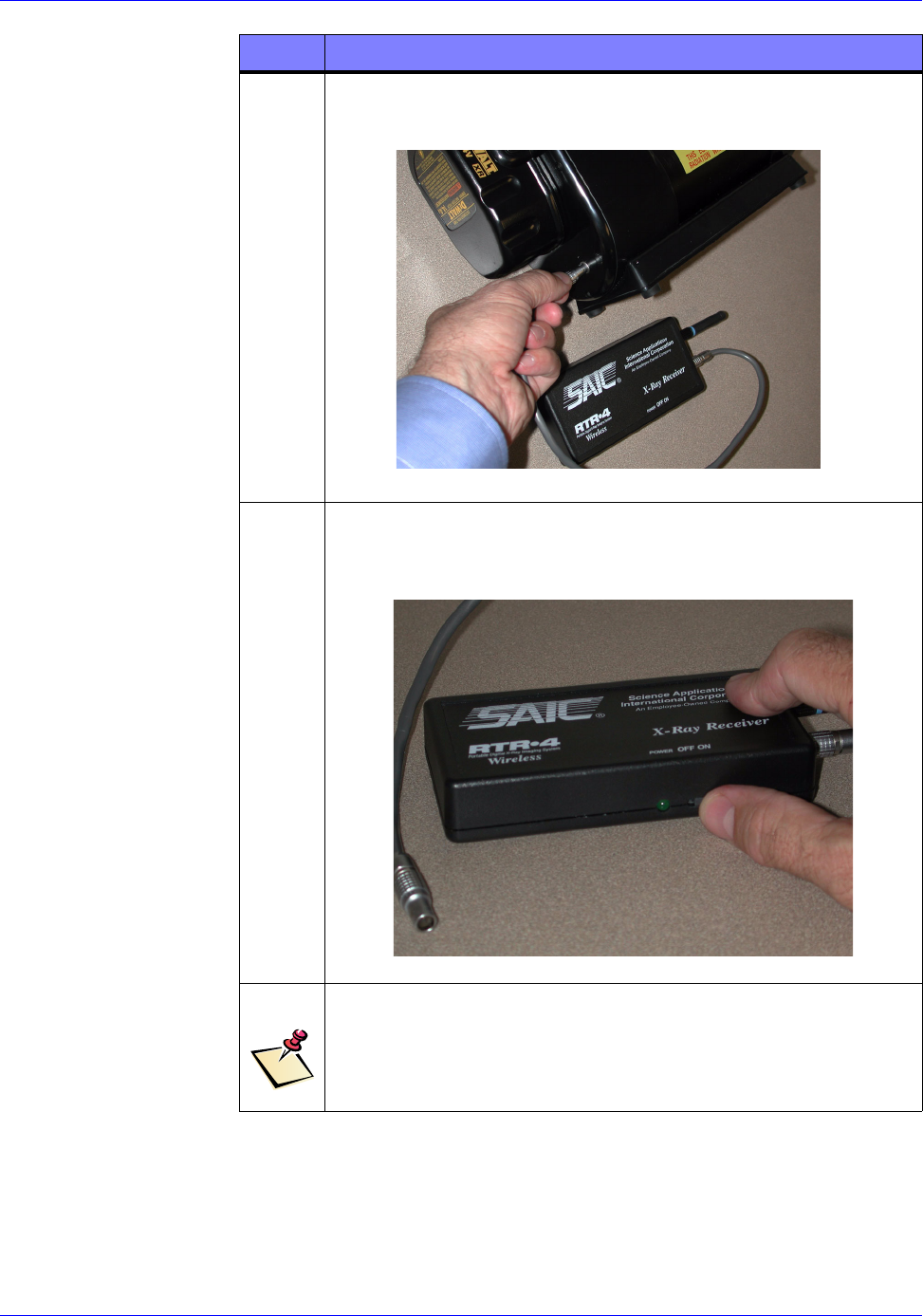
1Remove the X-ray Receiver from the packing case. Screw in
its supplied antenna and attach single X-ray Receiver cable
into the X-ray Receiver’s socket near the antenna as shown
below
2Attach the X-ray Receiver to the XR200 via its rear-mounted
Velcro strip.
RTR-4 Portable Digital X-Ray Imaging System--Operator’s Manual Supplement
306847 Rev A SAIC Proprietary 4-5
3Insert the other end of the X-ray Receiver’s cable to the
appropriate socket in the XR200 as shown below:
4Power up the X-ray Receiver by sliding its On/Off switch to
the On position as shown below. The green LED next to the
switch should illuminate.
NOTE
If the green LED fails to illuminate, replace the X-ray
Receiver battery in accordance with the procedure in
Chapter 6.
STEP ACTION
RTR-4 Portable Digital X-Ray Imaging System--Operator’s Manual Supplement
4-6 SAIC Proprietary 306847 Rev A
WiFi NIC Setup
WiFi NIC Setup Description
The Orinoco WiFi NIC must be properly installed and configured
in the CU-4/NCU in order for the Wireless Option to function
properly. Both CU-4 and NCU procedures are shown as required.
Prerequisites
The Power/Transceiver Setup and X-ray Receiver Setup
procedures must have been completed.
WiFi NIC Setup Procedure
The WiFi NIC is installed and configured as follows:
STEP ACTION
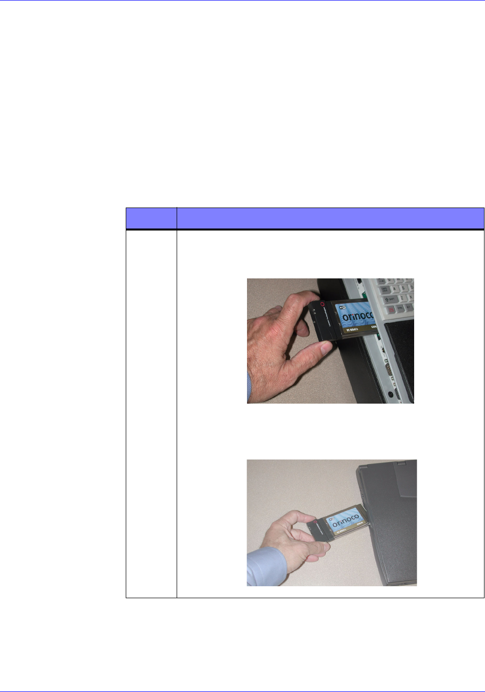
1Carefully insert and seat the WiFi NIC into the respective
CU-4 PCMCIA slot located on the left side of the computer
as shown below.
Carefully insert and seat the WiFi NIC into the respective
NCU PCMCIA slot located on the left side of the computer
as shown below.
RTR-4 Portable Digital X-Ray Imaging System--Operator’s Manual Supplement
306847 Rev A SAIC Proprietary 4-7
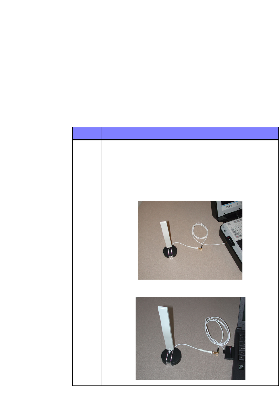
Optional Extended-Range Antenna Installation
Optional Extended-Range Antenna Installation
The Extended-Range Antenna is not required for wireless
operation, but when used, increases the system’s signal strength
and effective operating range. Both CU-4 and NCU antenna
installation procedures are shown.
Prerequisites
The WiFi NIC Setup procedure must have been completed.
Extended-Range Antenna Installation Procedure
The Extended-Range Antenna is installed and configured as
follows:
STEP ACTION
1Remove the small black antenna cable slot cover on the left
side of the NIC. Stow the cover in a safe place.
Carefully insert and tighten the antenna cable’s L-shaped
brass connector onto the antenna extension cable. Then
carefully insert and seat the flat connector on other end of
the cable into the WiFi NIC card slot in the CU-4 or NCU
respectively as shown in the figures below.