Lutron Electronics 0105 PowPak Dimming Module Relay Control User Manual Manual PWM
Lutron Electronics Company Inc PowPak Dimming Module Relay Control Manual PWM
Contents
- 1. Manual PWM
- 2. Manual 2
Manual PWM
Need Help? visit www.lutron.com.jp or call Lutron® Technical Support at 0120.083.417
041434
Rev. A
01/2014
Part of the Energi TriPak® Family
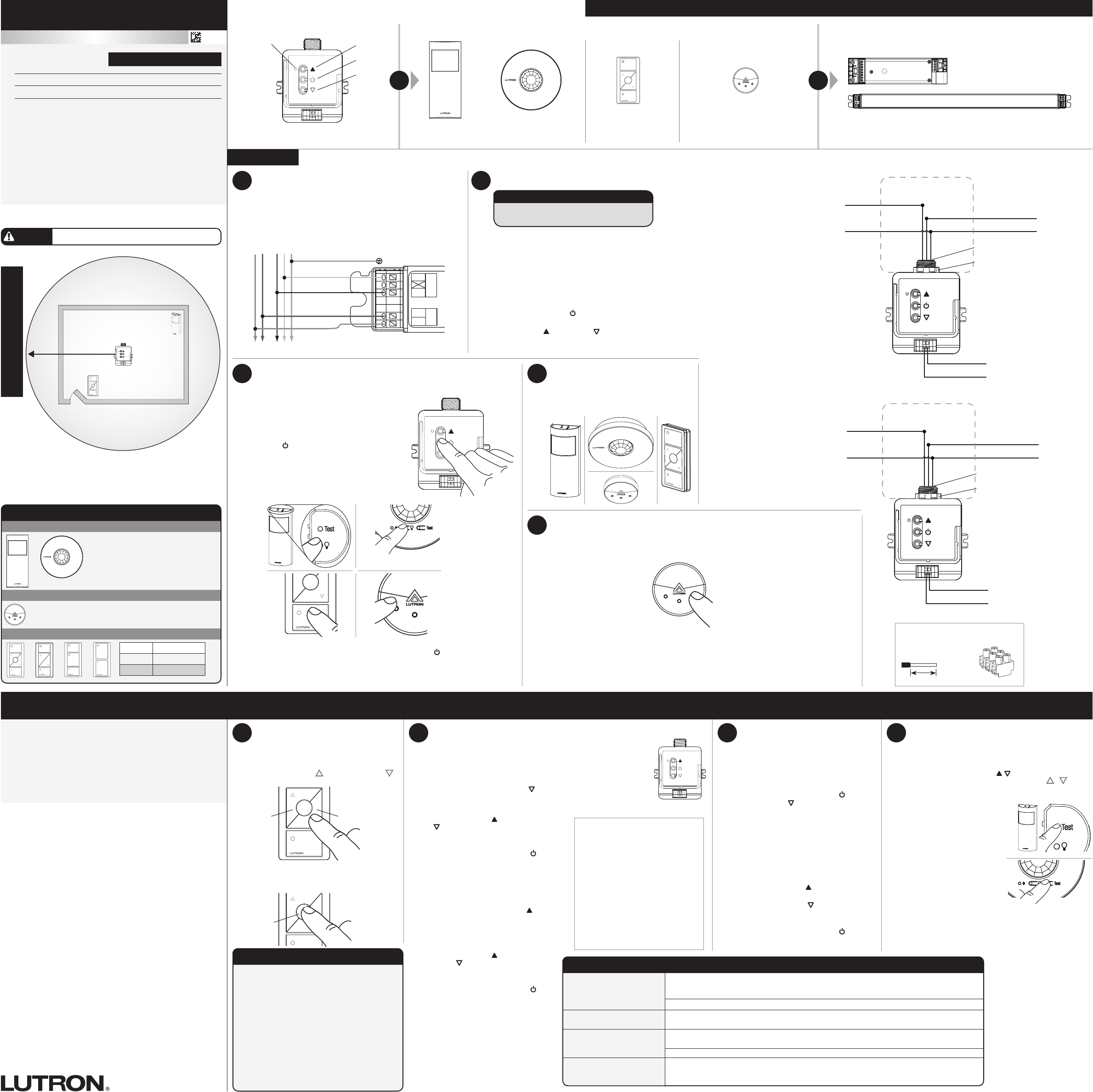
PowPak® | Installation
Dimming Module with PWM / 0 – 10 V
Test
Link Cal. +
For each system, ensure that you have:
One PowPak® PWM Dimming Module At least one Wireless Transmitter At least one PWM or 0 – 10 V- Fluorescent Ballast or LED Driver
Required Components
Radio Powr SavrTM Occupancy/Vacancy Sensor
(6 maximum)
Radio Powr SavrTM Daylight Sensor
(1 maximum)
Pico® Wireless Control
(9 maximum)
Switches up to 5 A total. May be pre-installed in light fixtu e.
Control line current - PWM: 150 mA max; 0-10 V-: 60 mA
PowPak® Dimming Module with
PWM / 0 – 10 V- (1 maximum)
Raise
Toggle
Lower
Load Status LED Consult third-party fixtu es installation guide for fixtu e-specific wiring.
Start Here
+
Occupancy Sensors
Daylight Sensor
Wireless Controls
Occupied: All lights 100%.
Unoccupied: All lights off.
Test
Link Cal.
All lights dim in response to daylight.
On All lights 100%
Favorite All lights 50%
Off All lights off
Default Functionality
Reset Factory Defaults
Note: In some instances, it may be necessary
to reset the PowPak® Dimming Module and
connected devices back to factory default
settings. Before beginning, make sure that all
devices are connected and powered.
A
Triple-tap any button on the PowPak® Dimming
Module and hold until the LED begins to flash
slowly; release button.
B
Within 3 seconds of the start of flashing,
triple-tap the same button again and the LEDs
will flash rapidly indicating that the unit has
been reset to factory defaults.
Note: Any associations or programming
previously set up with the PowPak® will be
erased and will need to be re-programmed.
2Install PowPak® Dimming Module
If installing unit inside a junction box please
see Lutron P/N 369674.
For more information: www.lutron.com/powpakrelay
A
PowPak® Dimming Module can be installed in a junction box or
marshalling box using the conduit nut (provided) or with mounting
screws (not provided). Please consult local and national electric
codes for proper installation.
B
Once installed, energize the PowPak® Dimming Module.
C
Use the Toggle button “ ” to toggle between high-end and OFF
to verify ballast wiring.
D
Use the Raise “ ” and Lower “ ” buttons to verify control wiring.
ALL PROGRAMMING IS OPTIONAL
Programming is not required for default functionality
• Set a favorite light level
• Set high-end and low-end trim for all fixtu es
• Set occupancy levels
•Set minimum light level for all fixtures
Please consult individual component installation and
programming guides for more details.
8Set Minimum Light Level
Certain applications (e.g., hallways), may
require that the lights never turn off. For
these areas, activate Minimum Light Level
mode.
A
Enter minimum light level adjustment
mode:
Press and hold Toggle button “ ” and
Lower button “ ” for 12 seconds. Lights
will flash hig -low-high and LED will begin
flashing
If lights stop flashing and go to high-end,
the minimum light level is set to OFF
(default).
If lights stop flashing and go to low-end,
the minimum light level is ON and set to
low-end.
B
Change the minimum light level:
Press Raise button “ ” to set minimum
light level to low-end.
Press Lower button “ ” to set minimum
light level to OFF.
C
Save the minimum light level:
Press and hold Toggle button “ ” for
6 seconds. LED will quickly flash to
indicate that new level has been saved.
Limited Warranty
(Lutron Asuka Company, Ltd., will, at its option, repair or replace any unit that
is defective in materials or manufacture within one year after purchase. For
warranty service, return unit to place of purchase, or mail to Lutron Asuka
Company, Ltd., No. 16 Kowa Building, 4F 1-9-20, Akasaka, Minato-ku Tokyo
107-0052 Japan, postage pre-paid, or telephone Lutron Asuka Company, Ltd.,
at 03.5575.8411.
This warranty is the sole express warranty, and the implied warranty of
merchantability, as well as the implied warranty under the Japanese Civil Code
(kashi-tampo), is limited to one year from purchase. This warranty does not
cover the cost of installation, removal, or reinstallation, or damage resulting
from misuse, abuse, or improper or incorrect repair, or damages from improper
wiring or installation. This warranty does not cover incidental, consequential,
or any special damages. Lutron Asuka Company’s liability on any claim for
damages arising out of or in connection with the manufacture, sale, installation,
delivery, or use of the unit shall never exceed the purchase price of the unit.
Lutron, Pico, and PowPak are registered trademarks and Radio Powr
Savr is a trademark of Lutron Electronics Co., Inc.
©2013 Lutron Electronics Co., Inc.
7Set Low-End and High-End Trim
Low-End Trim
A
Enter low-end trim adjustment mode:
Press and hold Lower button “ ” for 12 seconds.
Lights will flash high-low-high and LED will begin flashin
B
Adjust the low-end trim:
Use Raise button “ ” and Lower button
“ ” to adjust and set the lights to the
desired low-end (1to 45%).
C
Save the low-end trim:
Press and hold Toggle button “ ” for
6seconds to save setting.
LED will begin flashing and then tu n solid
to indicate new level has been saved.
High-End Trim
D
Enter high-end trim adjustment mode:
Press and hold Raise button “ ” for
12seconds.
Lights will flash high-low-high and LED
will begin flashing
E
Adjust the high-end trim:
Use Raise button “ ” and Lower
button “ ” to adjust and set the lights
to the desired high-end (55to 100%).
F
Save the high-end trim:
Press and hold Toggle button “ ” for
6 seconds to save setting.
LED will begin flashing and then tu n
solid to indicate new level has been
saved.
PowPak® | Programming
Daylight Override
Pressing the raise button on an
associated Pico® Wireless Control will
temporarily override daylighting.
Daylight Re-Enable
Daylighting will be re-enabled when one
of the following occurs:
• Two hours have passed since the
override.*
• ON, OFF, or Favorite button has been
pressed on a Pico®Wireless Control.
• All associated Occupancy Sensors have
reported unoccupied.
* Each time a daylighting override occurs,
the two-hour timer is reset.
English
WARNING
Shock Hazard. May result in serious injury or death.
Turn off power at circuit breaker before installing the unit.
All Wireless
Transmitters
must be
installed within
7 m of the
PowPak® Dimming Module.
Lutron Electronics Co., Inc.
7200 Suter Road
Coopersburg, PA 18036-1299 U.S.A.
PWM Control: 12 V- 150 mA
0 – 10 V- Control: 10 V- 60 mA
Important Notes: Please read before installing.
For installation by a qualified electrician in acco dance with all
local and national electrical codes.
• Note: Use copper conductors only.
•Check to see that the device type and rating is suitable for the
application.
• DO NOT install if product has any visible damage.
•If moisture or condensation is evident, allow the product to dry
completely before installation.
•Operate between 0 °C and 40 °C ambient.
•0% to 90% humidity, non-condensing.
•For indoor use only.
120 / 277 V~ 50 / 60 Hz 5 A
LMJ-5PWM-DV-B
Radio Powr SavrTM
Occupancy Sensor
Pico®
Wireless Control
PowPak®
Dimming
Module
7 m max
12 m
10 m
PowPak® Dimming Module
Install in center of room
to maximize RF coverage.
6Set a Favorite Light Level
For Pico® Wireless Controls with a Favorite
Button.
A
Adjust lights to desired level:
Use Raise button “ ” or Lower button “ ”
on Pico® Wireless Control.
B
Save favorite level:
Press and hold Favorite button for
6seconds.
Raise Lower
Mount, Wire, and Install PWM/0 – 10 V-
Devices and Lighting Fixtures
Consult third-party device installation guide
Turn off power at circuit breaker before installing unit.
A
Connect mains wiring (switched hot, neutral) to each fixtu e.
B
Connect low-voltage control (+ and – ) to each fixtu e.
1
+
–
NEU
HOT
Class 2
MAINS
Fixture Earth
Green/Yellow
To additional fixtu es
Neutral
Switched Hot
Violet
Gray
+
–
Sample ballast shown
Wiring for 200 V~ applications:
(requires a 2-pole input breaker)
Wiring for 100 V~ applications:
Switched Hot (Yellow)
–
Hot (Black)
To fixtu es
Control line to fixtu es*
Neutral (White)
+
Neutral (White)
Junction Box
21 mm Knockout Opening
Conduit Nut
* Use 0.75 mm2 to 1.5mm2 solid
wire only
3Associate Wireless Transmitters to PowPak®
Dimming Module
Before beginning this step, make sure that
there are no other PowPak® modules being set
up within the same building. It is possible that
wireless transmitters from other systems can
be incorrectly associated to this module.
A
On PowPak® Dimming Module, hold Toggle
button “ ” for 6 seconds until lights flash
The Load Status LED will begin flashing twice
per second.
B
Hold the indicated button on each transmitter
for 6seconds. Lights will flash to show that
wireless transmitters have been associated.
C
On PowPak® Dimming Module, hold Toggle button “ ” for 6 seconds to save
association. Lights will flash and LED will quickly blink for 2seconds.
4Install Wireless
Transmitters
Note: Please consult individual component
installation guides for information.
Test
Link
5
A
Set lights in room to desired light level.
B
Press and hold “Cal.” for
6seconds.
C
Exit room for 5 minutes to
complete calibration.
Note: When calibration has
completed, all lights will flash
and begin daylighting.
Multiple Daylight Rows
(OPTIONAL)
For every row of daylighting a separate PowPakR
Dimming Module must be used. For detailed setup
refer to the tuning section of the Radio Powr SavrT
Daylight Sensor installation guide.
• Select the PowPakR Dimming Module that you
want to adjust by pressing the toggle button
Calibrate Daylight Sensor
Daylight Sensor will control all wired fixtu es equally.
9Set Occupancy Light Levels
Note: Unoccupied light level is always the minimum light
level and cannot be adjusted.
A
Set desired occupancy light levels:
Use Raise/Lower buttons “ / ” on the PowPak®
Dimming Module or Raise/Lower buttons “ / ” on all
associated Pico® Wireless Controls.
Note: If certain lights should be
unaffected by occupancy, turn
lights off using PicoR Wireless
Control(s).
B
Save occupancy light levels:
Press and hold Test button for
6 seconds on any associated
Radio Powr SavrTM Occupancy
Sensor without a “a” button.
Release when Sensor lens
starts to flash
Or, press and hold “a”
button for 6 seconds on
any associated Radio Powr
SavrTM Occupancy Sensor.
Release when Sensor lens
starts to flash
Notes
Depending on the fixtu e
manufacturer or load, low-end
and high-end trim may need to be
adjusted.
• Trim low-end to ensure a stable
light level because some loads will
flicker or d op out if trimmed too
low.
• Be sure that you can turn on the
lights to the low-end trim level
without any abnormal operation.
• The factory default high-end trim
will normally be sufficient for mos
applications. Trim as desired.
Favorite
Troubleshooting www.lutron.jp
Ballasts cannot be controlled
locally from PowPak®
Dimming Module.
• Ensure that the breaker(s) to the PowPak® Dimming Module are energized.
• Ensure that the PowPak® Dimming Module switched hot lead is wired to the ballast(s).
• Ensure that the PowPak® Dimming Module 0 –10 V control lines are wired to the ballast(s).
• Reset to factory defaults.
Lights do not dim as
expected.
• Ensure that 0 –10 V control lines are wired properly.
• Ensure that fixtu e does not require an inverted signal (10 – 0 V control)
Lights do not respond to
Wireless Transmitter(s).
• Ensure that the breaker(s) to the PowPak® Dimming Module and ballasts are energized.
• Ensure that Wireless Transmitters are associated to the PowPak® Dimming Module.
• Reset to factory defaults.
Wireless Transmitter(s)
cannot be associated to
PowPak® Dimming Module.
• The maximum number of Wireless Transmitters have been associated to the PowPak® Dimming
Module. To remove a previously set up Wireless Transmitter, tap a Wireless Transmitter button
three times; on the third tap hold for three seconds and then tap three more times.
Switched Hot (Yellow)
–
Hot 1 (Black)
To fixtu es
Control line to fixtu es*
Hot 2 (White)
+
Hot 2 (White)
Junction Box
21 mm Knockout Opening
Conduit Nut
* Use 0.75 mm2 to 1.5mm2 solid
wire only
Suggested Installation Location:
Install in center of room.
This ensures proper RF coverage of area.
Test
Link
Cal.
Supplied Terminal Information
Strip Length: 9 mm
Torque: 2 N•m
9 mm
Test
Link Cal.
FCC Information (LMJ- and ULMJ- only)
This device complies with part 15 of the FCC Rules and Industry Canada license-exempt
RSS standard(s). Operation is subject to the following two conditions: (1) This device
may not cause interference, and (2) this device must accept any interference, including
interference that may cause undesired operation. Modifications not expressly approved by
Lutron Electronics Co., Inc. could void the user’s authority to operate this equipment. NOTE:
This equipment has been tested and found to comply with the limits for a Class B digital
device, pursuant to part 15 of the FCC Rules. These limits are designed to provide
reasonable protection against harmful interference in a residential installation. This equipment
generates, uses and can radiate radio frequency energy and, if not installed and used in
accordance with the instructions, may cause harmful interference to radio communications.
However, there is no guarantee that interference will not occur in a particular installation. If
this equipment does cause harmful interference to radio or television reception, which can
be determined by turning the equipment off and on, the user is encouraged to try to correct
the interference by one or more of the following measures:
Re-orient or relocate the receiving antenna.
Increase the separation between the equipment and receiver.
Connect the equipment into an outlet on a circuit different from that to which the receiver
is connected.
•
•
•