Mitel Deutschland 68635RFP36U-01 Set of IP-DECT Base Station and directional antenna User Manual SIP DECT OM System Manual
Mitel Deutschland GmbH Set of IP-DECT Base Station and directional antenna SIP DECT OM System Manual
Contents
- 1. UserManual_part1
- 2. UserManual_part2
- 3. UserManual.pdf
UserManual.pdf

SIP-DECT OM System Manual
INSTALLATION, MAINTENANCE & ADMINISTRATION GUIDE
RELEASE 6.1

NOTICE
The information contained in this document is believed to be accurate in all respects but is not warranted
by Mitel Networks™ Corporation (MITEL®). The information is subject to change without notice and
should not be construed in any way as a commitment by Mitel or any of its affiliates or subsidiaries. Mitel
and its affiliates and subsidiaries assume no responsibility for any errors or omissions in this document.
Revisions of this document or new editions of it may be issued to incorporate such changes.
No part of this document can be reproduced or transmitted in any form or by any means - electronic or mechanical
- for any purpose without written permission from Mitel Networks Corporation.
TRADEMARKS
The trademarks, service marks, logos and graphics (collectively "Trademarks") appearing on Mitel's Internet sites
or in its publications are registered and unregistered trademarks of Mitel Networks Corporation (MNC) or its
subsidiaries (collectively "Mitel") or others. Use of the Trademarks is prohibited without the express consent from
Mitel. Please contact our legal department at legal@mitel.com for additional information. For a list of the worldwide
Mitel Networks Corporation registered trademarks, please refer to the website: http://www.mitel.com/trademarks.
SIP-DECT OM System Manual
Release 6.1
November 2015
®,™ Trademark of Mitel Networks Corporation
© Copyright 2015 Mitel Networks Corporation
All rights reserved

iii
CONTENTS
1 Overview .......................................................................................................................................................... 10
1.1 The SIP-DECT Solution 10
1.2 About DECT Base Stations 11
1.2.1 DECT Base Station Families 11
1.2.2 RFP only Mode 14
1.2.3 OpenMobility Manager (OMM) Mode 14
1.3 About the OpenMobility Manager 14
1.3.1 OMM Tasks 15
1.3.2 SIP-DECT Special Features and Capabilities 16
1.3.3 OMM Capacities and Features 16
1.4 About DECT Phones 17
1.5 File naming conventions 17
1.6 Login and passwords 18
2 Getting Started ................................................................................................................................................ 19
2.1 Base Station Startup Configuration 19
2.2 System Configuration 19
2.3 System Settings 20
2.4 Base Stations 21
2.5 SIP settings 22
2.6 DECT Phones 23
2.6.1 DECT Phone and SIP state verification 24
3 Enhanced Feature Overview ......................................................................................................................... 25
3.1 Download over Air 25
3.2 Wideband (CAT-iq 1.0 / Mitel Hi-Q™ audio technology) 25
3.3 Conferencing 26
3.3.1 Conferencing audio notification 26
3.3.2 Centralized Conferencing with MiVoice Business 26
3.4 VoIP encryption 27
3.5 DECT enhanced security 27
3.6 SIP over UDP/TCP/TLS 28
3.7 SIP multiport 28
3.8 Mixed base station installations 29
3.9 DECT XQ 29
3.10 UTF-8 encoding 30
3.11 Alphanumeric dialing 30
3.12 Voice mail number 31
3.13 Call handling 31
3.13.1 Diversion indication 31
3.13.2 Call completed elsewhere 32
3.13.3 Semi-Attended Transfer 32
3.13.4 Third Line Handling for Mitel 142d and 600 DECT Phones 32
3.13.5 Call Transfer Enhancements for Mitel 142d DECT phones 33
3.14 Truncating SIP User Name in SIP URI 33
3.15 System redundancy 34
3.15.1 OMM standby 34
3.15.2 Backup SIP proxy/registrar 34
3.15.3 Configurable User Account for Standby Check 34
3.15.4 User data synchronization (MiVoice 5000 dual homing support) 35
3.16 DECT base station synchronization 35
3.16.1 Clustering and paging areas 35
3.17 Wireless LAN (WLAN) 35
3.17.1 802.11i: WPA2-Enterprise Pre-Authentication for fast Roaming 35
3.17.2 Channel Configuration Feedback for HT40 and tx Power 36
3.18 PC-based OMM installation 36
3.19 OM Locating application 36
3.20 Video support 36

iv
3.20.1 USB Video Devices 37
3.20.2 Terminal Video 37
3.21 Mitel 600 DECT Phone Dial Editor Mode 38
3.22 Mitel 602 DECT Phone Customizable Boot Texts 39
3.23 Extended messaging 39
3.24 OpenMobility DECT phone provisioning 39
3.25 User monitoring 40
3.26 SIP-DECT XML terminal interface 40
3.26.1 Feature Access Codes Translation 40
3.26.2 Ring Tone Selection for (Alarm) Messages 41
3.27 Central DECT Phone Configuration Over Air (CoA) 41
3.27.1 CoA enhancements 42
3.28 Integration of corporate directories 42
3.29 Integration into external management systems 42
3.30 System configuration tools 42
3.31 Simplified licensing 43
3.32 Extended regulatory domain support 43
3.33 DECT base station Reset to Factory Settings 44
3.34 SIP enhancements 44
3.34.1 Globally Routable User-Agent URIs (GRUUs) 44
3.34.2 Session timer 44
3.34.3 SIP Contact matching 44
3.34.4 Configurable Call reject state codes 44
3.34.5 Call release timers 45
3.34.6 Incoming call timeout 45
3.35 Auto answer, intercom calls and audio settings 45
3.35.1 Intercom Calls 45
3.35.2 Auto answer audio settings 46
4 Licensing ......................................................................................................................................................... 47
4.1 Licensing Model 47
4.1.1 System Licenses 47
4.1.2 About G.729 Channels 48
4.1.3 PARK Service 48
4.1.4 Upgrade License 49
4.1.5 Grace Period 49
4.1.6 License Violations and Restrictions 50
4.2 Uploading a License File 50
4.3 License Models 51
4.3.1 Small System (Unlicensed) 51
4.3.2 Medium or Large System 51
5 OMM Web Service ........................................................................................................................................... 52
5.1 Login 52
5.2 Logout 53
5.3 “Status” Menu 53
5.4 “System” Menu 54
5.4.1 “System Settings” Menu 54
5.4.2 ”Provisioning” Menu 64
5.4.3 ”SIP” Menu 66
5.4.4 “User administration” Menu 76
5.4.5 “Time zones” Menu 77
5.4.6 “SNMP” Menu 78
5.4.7 “DB management” Menu 79
5.4.8 “Event log” Menu 82
5.5 “Sites” Menu 83
5.5.1 Creating a New Site 83
5.5.2 Editing a Site 84
5.5.3 Deleting a Site 84
5.6 “Base Stations” Menu 84
5.6.1 Base Station States 85

v
5.6.2 OMM / RFP Software Version Check 86
5.6.3 Creating and Changing Base Stations 86
5.6.4 Capturing Base Stations 88
5.6.5 Deleting RFPs 89
5.7 “DECT Phones” Menu 89
5.7.1 Creating and Changing DECT Phones 90
5.7.2 Importing DECT phone Configuration Files 91
5.7.3 Subscribing DECT Phones 92
5.7.4 Deleting DECT phones 94
5.7.5 Searching the DECT phone List 94
5.7.6 Displaying User and DECT Phone Data 94
5.8 “WLAN” Menu 99
5.8.1 “WLAN profiles” Menu 99
5.8.2 “WLAN clients” Menu 104
5.9 “System features” Menu 104
5.9.1 “Digit treatment” Menu 104
5.9.2 “Directory” Menu 106
5.9.3 “Feature Access Codes” Menu 108
5.9.4 ”XML Applications” Menu 110
5.10 “Licenses” Menu 111
5.11 “Info” Menu 111
6 OM Management Portal (OMP) ...................................................................................................................... 112
6.1 Login 112
6.2 Logout 113
6.3 OMP Main Window 113
6.4 “Status” Menu 115
6.4.1 Overview 115
6.4.2 DECT base stations 117
6.4.3 Users 118
6.4.4 Devices 119
6.4.5 Sites 120
6.4.6 Conference 120
6.4.7 Video Devices 121
6.5 “System” Menu 121
6.5.1 “Basic settings” Menu 122
6.5.2 “Advanced settings” Menu 125
6.5.3 “Statistics” Menu (Monitoring Mode Only) 138
6.5.4 “SIP” Menu 139
6.5.5 ”Provisioning” Menu 148
6.5.6 “User administration” Menu 152
6.5.7 “Data management” Menu 155
6.5.8 “Event Log” Menu 160
6.6 “Sites” Menu 161
6.7 “DECT Base Stations” Menu 162
6.7.1 “Device list” Menu 162
6.7.2 “Paging areas” Menu 169
6.7.3 “Capturing” Menu 171
6.7.4 “Enrolment” Menu 171
6.7.5 “Export” Menu 172
6.7.6 “Sync view” Menu 173
6.7.7 “Statistics” Menu 174
6.7.8 “Quality” Menu 175
6.8 “WLAN” Menu 178
6.8.1 Profiles 178
6.9 “Video devices” Menu 181
6.9.1 Changing Video Devices 181
6.9.2 Viewing Video Device Details 182
6.9.3 Deleting Video Devices 182
6.9.4 Filtering Video Device Table 182
6.10 “DECT Phones” Menu 183

vi
6.10.1 ”Overview” Menu 183
6.10.2 “Users” Menu 185
6.10.3 “Devices” Menu 186
6.10.4 Device Detail Panel 186
6.10.5 Creating DECT phone Datasets 195
6.10.6 Configuring DECT phone Datasets 195
6.10.7 Subscribing DECT phone Datasets 195
6.10.8 Deleting DECT phone Datasets 196
6.10.9 Selecting Columns 196
6.10.10 Filtering DECT phone Table 196
6.10.11 Changing the Relation Type 197
6.10.12 Enabling / Disabling DECT phone Event Log 197
6.10.13 User Monitoring 198
6.11 “Conference rooms” Menu 199
6.11.1 Creating Conference Rooms 199
6.11.2 Configuring Conference Rooms 200
6.11.3 Deleting Conference Rooms 200
6.11.4 Viewing Conference Room Details 200
6.12 “System features” Menu 200
6.12.1 “General settings” Menu 201
6.12.2 “Feature access codes” Menu 201
6.12.3 “Alarm triggers” Menu 202
6.12.4 “Digit treatment” Menu 204
6.12.5 “Directory” Menu 205
6.12.6 “XML applications” Menu 207
6.12.7 “CoA Profiles” Menu 210
6.13 “License” Menu 211
6.14 “General” Menu 214
6.15 “Help” Menu 215
7 Configuration and Administration ................................................................................................................ 217
7.1 IP Signaling and Media Stream 217
7.2 RFP Synchronization 220
7.2.1 Initial Synchronization Procedure 221
7.2.2 Checking the Synchronization of a Network 222
7.3 RFP Channel Capacity 222
7.4 Network Infrastructure Prerequisites 223
7.5 SIP-DECT Startup 223
7.5.1 TFTP and DHCP Server Requirements 223
7.5.2 Booting Steps 224
7.5.3 Booter Startup 225
7.5.4 Application Startup 227
7.5.5 RFP LED Status 230
7.6 State Graph of the Start-up Phases 233
7.7 Local DECT Base Station Configuration (OM Configurator) 235
7.7.1 Selecting the Network Interface 235
7.7.2 Adding RFPs for configuration 236
7.7.3 Scanning for RFPs 236
7.7.4 Adding RFPs manually 237
7.7.5 Loading RFP data from File 237
7.7.6 Editing RFP configuration data 237
7.7.7 Applying Configuration Changes 240
7.7.8 Factory Reset 240
7.7.9 Saving and Loading an RFP List 240
7.7.10 Removing RFP Entries 241
7.7.11 Compatibility with Older SIP-DECT Releases 241
7.8 OMM Configuration and Resource Files 241
7.8.1 Configuration File URL 242
7.8.2 Specific Configuration URLs 243
7.8.3 ReLoad of Configuration and Resource files 244
7.8.4 AXI Commands in Configuration Files 245

vii
7.8.5 User Configuration Files 247
7.8.6 Digest Authentication and Certificate Validation 248
7.8.7 RFP software Image from RFP OMM 249
7.8.8 Redirection and Configuration Service (RCS) 249
7.8.9 Customer Logo on OMM Web Service 250
7.9 RFP Configuration Files 251
7.9.1 Standard IP settings 251
7.9.2 Configuration file source 251
7.9.3 Parameter settings priority 252
7.9.4 Software update settings for 3rd generation RFPs 252
7.9.5 Times when RFP configuration times are read 252
7.9.6 RFP configuration file update check 253
7.9.7 Handling of parameter changes 254
7.9.8 Configuration file syntax 254
7.10 Consolidated Certificate management 256
7.10.1 SIP over TLS certificates 256
7.10.2 OMM Certificate (Web service / AXI) 256
7.10.3 Provisioning certificates 256
7.10.4 Certificate validation 257
7.11 RFP 35/36/37 IP / RFP 43 WLAN Software Update 257
7.12 802.1Q Support 257
7.12.1 Boot Phase of IP RFPs (DHCP) 258
7.12.2 Boot Phase of IP RFPs (Local Configuration) 259
7.13 Installing OMM in Host Mode 259
7.13.1 System Requirements 259
7.13.2 Installing the OMM Software 259
7.13.3 Configuring the Start Parameters 260
7.13.4 Specific Commands – Troubleshooting 261
7.14 Updating the OMM 261
7.14.1 Updating a Single OMM Installation 262
7.14.2 Updating a Standby OMM Installation 262
7.15 OMM Standby 264
7.15.1 Configuring OMM Standby 264
7.15.2 Fail Over Situations 264
7.15.3 Failover Failure Situations 265
7.15.4 Specific standby situations 266
7.16 User data synchronization (MiVoice 5000 dual homing support) 267
7.16.1 Roaming 268
7.16.2 Setting up user data synchronization 269
7.16.3 User data synchronization modes 270
7.17 Managing Account Data for System Access 271
7.17.1 Account Types 272
7.17.2 Potential Pitfalls 272
7.18 WLAN Configuration (RFP 42 WLAN / RFP 43 WLAN only) 273
7.18.1 WLAN configuration steps 273
7.18.2 Optimizing the WLAN 274
7.18.3 Securing the WLAN 275
7.19 SNMP Configuration 276
7.20 Backup SIP Proxy/Registrar 276
7.20.1 REGISTER Redirect 276
7.20.2 DNS SRV 277
7.20.3 Backup SIP Servers 278
7.20.4 Keep Alive Mechanism 281
7.20.5 Prioritized Registration 281
7.20.6 Monitoring the SIP Registration Status 281
7.20.7 Configurable User Account for Standby Check 282
7.20.8 OMM Standby Enhancement 282
7.21 Conferencing 283
7.21.1 Centralized Conferencing 284
7.21.2 Integrated Conference Server (ICS) 284
7.21.3 Configure conference rooms 286

viii
7.22 Download Over Air 288
7.22.1 How “Download Over Air” Works 289
7.22.2 How to configure “Download Over Air” 289
7.23 Central DECT Phone Configuration Over Air (CoA) 292
7.23.1 Configuration files 292
7.23.2 Configuration file download to DECT phones 293
7.23.3 CoA Configuration using OMP 293
7.23.4 Configuration using usr_common.cfg/<user>/cfg Files 294
7.23.5 Variable lists 295
7.24 Extended DECT Phone Interface 300
7.25 OMM/DECT Phone Lock with Branding ID 301
7.25.1 Subscribing the DECT Phone 301
7.26 Device Placement 302
7.26.1 “Placement” View 302
7.26.2 “DECT Base Stations” View 303
7.26.3 “Image management” View 303
7.27 Monitoring with USB Video Devices 305
7.27.1 Configuration of a video user account 306
7.27.2 Configuration of USB video devices 306
7.27.3 Monitoring with USB video devices 306
7.28 Terminal Video 307
7.28.1 Technical Details 307
7.28.2 OMP Configuration Steps 307
7.28.3 Camera Selection via Handset Menu 308
7.29 User Monitoring 308
7.29.1 Overview 308
7.29.2 Status Attributes and Validation Mechanisms 310
7.29.3 Escalation 313
7.29.4 Alarm Triggers 313
7.29.5 OM Locating Application 313
7.29.6 Licensing and System Capacities 314
7.29.7 Configuration 314
7.29.8 Start and Failover 316
7.29.9 Supported DECT phones 317
7.29.10 Restrictions 318
7.30 SRTP 318
7.31 SIP over TLS 319
7.31.1 Certificates 320
7.31.2 Private Key 321
7.31.3 TLS Transport Mode 321
7.31.4 Verification of Remote Certificates 322
7.31.5 Additional Security Considerations 322
7.32 DECT Enhanced Security 323
7.33 Migration of RFP SL35 IP from SIP-DECT Lite 3.1 to SIP-DECT 6.1 323
8 Maintenance .................................................................................................................................................... 325
8.1 Site Survey Measurement Equipment 325
8.2 Checking the Mitel Handset Firmware Version 325
8.3 Diagnostic 325
8.3.1 Mitel DECT Phone Site Survey Mode 325
8.3.2 Mitel Handset Auto Call Test Mode 326
8.3.3 Mitel Handset Auto Answer Test Mode 326
8.3.4 Syslog 327
8.3.5 SSH user shell 328
8.3.6 Core File Capturing 332
8.3.7 DECT Monitor 333
9 Safety Information .......................................................................................................................................... 337
9.1 CE Marking 337
9.2 Communications Regulation Information 337
9.2.1 FCC Notices (U.S. Only) 337

ix
9.3 Health and Safety 338
9.3.1 Exposure to Radio Frequency (RF) Signals: 338
9.3.2 Industry Canada (Canada only) 338
9.4 Informations réglementaires en matière de communications 338
9.4.1 Notes FCC (USA uniquement) 339
9.5 Santé et sécurité 339
9.5.1 Exposition aux signaux radio (RF) 339
9.5.2 Industrie Canada (Canada uniquement) 339
10 Appendix ......................................................................................................................................................... 341
10.1 Pre-Configuration File Rules 341
10.1.1 DECT phone Configuration File (OMM Database) 341
10.2 RFP Configuration File / Central (OMM Database) 345
10.2.2 RFP Configuration File / Local (OM Configurator) 348
10.3 RFP Export File Format 352
10.4 COA Configuration Parameters 353
10.4.1 Extended COA example 353
10.4.2 Supported CoA Parameters 357
10.5 Protocols and Ports 376
10.6 Abbreviations 378
10.7 Definitions 379
10.8 References 381

SIP-DECT OM System Manual
10
1 OVERVIEW
This document describes the installation / configuration, administration, and maintenance of the SIP-
DECT solution. Please also see the documents listed in the References section (section 9.11) for
additional details on different aspects of the SIP-DECT system.
For a list of abbreviations and definitions, see the appropriate sections in the Appendix.
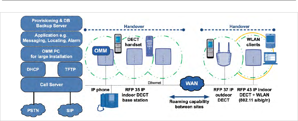
1.1 THE SIP-DECT SOLUTION
The SIP-DECT solution includes the following main components:
• SIP-DECT base stations that are distributed over an IP network and offer DECT, WLAN, and IP
interfaces
• DECT phones (portable DECT devices)
• OpenMobility Manager (OMM): Management and signaling software for the SIP-DECT solution, which
runs on one of the DECT base stations or on a dedicated Linux server (for large installations). In
addition, a standby OMM can be configured to ensure OMM function in case of failure or loss of
network connection.
• A SIP Call Manager/IP PBX/Media Server platform (e.g. Asterisk)
The IP PBX/media server/media gateway, OMM and the RFPs communicate through the IP
infrastructure. The RFPs and the DECT phones communicate over the air, where the DECT GAP
protocol or DECT GAP with proprietary enhancements is used.
The SIP-DECT solution supports seamless handover between RFPs which are in a group of
synchronized RFPs (cluster) and roaming between RFPs on remote sites.
Additional components include:
• LDAP server to facilitate a central corporate directory
• Provisioning server to provide RFP configuration or user data files
• Data backup server to automatically backup an OMM database from the server
• OM Locating server and clients to run the SIP-DECT locating solution
• 3rd party messaging or alarm server to integrate the SIP-DECT text messaging into a unified
messaging or alarm environment
• Computer for administration and maintenance tools: Web browser, OM Management Portal (OMP),
DECT Monitor
Overview
11
1.2 ABOUT DECT BASE STATIONS
DECT base stations are also referred to as Radio Fixed Parts (RFPs) in this document.
1.2.1 DECT BASE STATION FAMILIES
1.2.1.1 Current DECT Base Station Types
Mitel offers four types of DECT base stations for the SIP-DECT solution:
• RFP 35 IP
DECT RFP as indoor model
• RFP 36 IP
DECT RFP as outdoor model with built-in dipole antennas
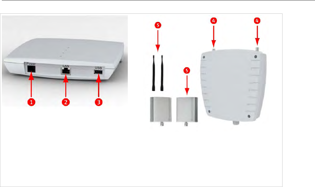
• RFP 37 IP
DECT RFP as outdoor model with connectors for external directional antennas
• RFP 37 DRC (Set)
DECT RFP, preinstalled with directional antennas and 3m cable in an outdoor enclosure
• RFP 43 WLAN
DECT RFP + WLAN Access Point as indoor model with internal antennas for DECT and WLAN
As of SIP-DECT 6.0, there is no distinction between DECT base station soft brands (i.e., L-RFPs and
non-L-RFPs). See section 4 for more information.
In general the RFP 35 / 36 / 37 IP have the same hardware platform and software capabilities. RFP 43
supports WLAN in addition to DECT.
SIP-DECT OM System Manual
12
1 Power 48V DC (optional)
2 1GBit Ethernet (PoE)
3 USB
4 DECT antenna connector (RFP 37 IP)
5 Antennas (RFP 37 IP)
The hardware of all the new RFPs complies with the different regulatory domains. There are no specific
hardware variants required to use specific frequency bands and field strengths. Transmit Power,
frequency band and carrier frequencies are controlled by software.
Other differences compared to the previous RFP family (RFP 32/34 IP and RFP 42 WLAN):
• boots from internal flash memory instead of net-boot (SIP-DECT software is already on board)
• software update via TFTP, FTP(S), HTTP(S), SFTP supported
• supports 1GBit Ethernet
• supports CAT-iq 1.0 level high definition voice for the Mitel 650 DECT phone
• hardware can support Secure SIP and SRTP (with SIP-DECT 5.0 or later)
• uses an external 48V DC Power Supply (if no PoE available) which meets the latest environmental
requirements (RFP 37: PoE only)
• RFP 43 WLAN supports the 802.11a/b/g/n standards
• any 3G RFP can host the OMM.
• indoor RFPs have a USB 2.0 interface to connect external hardware for future applications (e.g.,
video camera).
1.2.1.2 Older RFP Types
Older RFP models supported by the SIP-DECT solution include
• RFP 32 IP
DECT RFP as indoor model
• RFP 34 IP
DECT RFP as outdoor model
• RFP 42 WLAN
DECT RFP + WLAN Access Point as indoor model
Overview
13
The RFP 32 and RFP 34 have the same hardware and software capabilities. Please note the regulatory
differences between North America and other areas of the world. These differences lead to different RFP
32/34 variants which use specific frequency bands and field strengths:
• RFP 32 NA or RFP 34 NA (NA)
- Frequency Band 1920 to 1930 MHz
- 5 carrier frequencies
- Transmit Power 20 dBm
• RFP 32 IP or RFP 34 IP (EMEA)
- Frequency Band 1880 to 1900 MHz
- 10 carrier frequencies
- Transmit Power 24 dBm
The RFP 42 WLAN is only available for the EMEA region.
RFP 32 IP / RFP 32 NA
RFP 34 IP / RFP 34 NA
RFP 42 WLAN
1 Power jack (120 V/230 V AC adapter)
2 Ethernet jack; Power supply in line with Power over Ethernet standard IEEE 802.3af
As of SIP-DECT 6.0, there is no distinction between RFP soft brands (i.e., L-RFPs and non-L-RFPs).
With SIP-DECT 5.0 and older releases, the “L” variants have built-in licenses. See section 4 (Licensing)
for more information.
Note: The software package for previous RFPs has a tftp extension
e.g. “iprfp2G.tftp. With SIP-DECT 3.0 or higher, you need a 3G
RFP to run the Open Mobility Manager.

SIP-DECT OM System Manual
14
1.2.2 RFP ONLY MODE
Within this mode the RFP converts IP protocol to DECT protocol and then transmits the traffic to and
from the DECT phones over a DECT time slot. On air the RFP has 12 available time slots, 8 can have
associated DSP/media resources for media streams. All DECT time slots are used for control signaling,
software download over air, messaging and bearer handover independent of associated DSP/media
resources.
Two control signaling channels are also used to carry bearer signals that signal the DECT phone to start
the handover process. If the radio signal of another RFP is stronger than that of the current RFP, the
DECT phone starts the handover process to the RFP that has the stronger signal as the user moves
around the site.
Clusters
Groups of RFPs can be built which are named clusters. Within a cluster RFPs are synchronized to
enable a seamless handover when a DECT phone crosses from one RFP’s area of coverage to another.
For synchronization, it is not necessary for an RFP to have direct line of sight to all other RFPs in the
system. Each RFP only needs to be able to see the next adjacent RFP. But it is highly recommended
that an RFP have visibility to more than one RFP to guarantee synchronization in the event that one of
the RFPs fails.
1.2.3 OPENMOBILITY MANAGER (OMM) MODE
If the OMM is not running on a dedicated Linux server, one RFP within a SIP-DECT installation must be
declared to operate as the OpenMobility Manager (OMM). The RFP acting as the OMM may also act as
a regular RFP if it is part of a DECT cluster.
In OMM mode, an RFP functions as a regular RFP. Additionally, it is responsible for SIP signaling
between the SIP-DECT system and the IP PBX/SIP server. Further on, it takes over the management
part of the SIP-DECT solution. You designate an RFP as the OMM by assigning an IP address to the
RFP within the DHCP scope (see section 7.5) or by setting the data via the OM Configurator (see
section 7.7). After an RFP is designated as the OMM, it starts the extra services on board (for example,
the web service that supports the management interface). All RFPs download the same firmware (for
their RFP type), but only one RFP (or two, in standby implementations) activates the OMM services.
Note: It is possible to deactivate the DECT part of an RFP. If the DECT
interface is deactivated, all resources (CPU and memory) are
available for the OMM.
This might be necessary, for example, in configurations where a
mix of OpenMobility Manager, G.729/Conferencing and WLAN is
provided by the same RFP.
1.3 ABOUT THE OPENMOBILITY MANAGER
The OpenMobility Manager (OMM) requires an RFP 35/36/37 IP resp. RFP 43 WLAN, or a dedicated
Linux server.
There is only one OpenMobility Manager (OMM) active in the system at a given time.
• If the OMM runs on an RFP, a 100 MB network link is required.
• If the OMM runs on a dedicated Linux server, a 1 GB network link is required (see also section
7.13.1).
Overview
15
In addition, a standby OMM can be configured to ensure the OMM function in case of failure or loss of
network connection. For more information on the standby OMM see section 7.15.
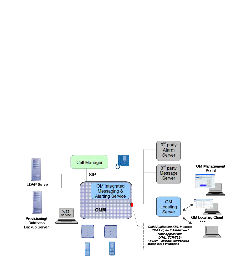
1.3.1 OMM TASKS
The OMM performs the following tasks:
• Signaling gateway (SIP <-> DECT)
• Media stream management
• Managing sync-over-air functions between RFPs
• Provides a Web service for system configuration
• Provides additional services such as
- LDAP based central corporate directory
- OM Application XML interface (OM AXI) for OAM&P, messaging, alerting service and locating
- Integrated Messaging and Alerting Service (OM IMA)
- Data backup and provisioning services
- SIP-DECT XML terminal interface. This interface adapts the “XML API for SIP Phones“ to SIP–
DECT phones. The Mitel 600 DECT phone family is supported.
Additional information on the following functionality is available in separate documents.
• Locating: see the SIP-DECT OM Locating Application Installation and Administration Guide.
• Integrated Messaging and Alerting Service: see the SIP-DECT OM Integrated Messaging and
Alerting Application Guide and the SIP-DECT Mitel 600 Messaging and Alerting Applications Guide.
• User data provisioning: see the SIP-DECT OM Handset Sharing and Provisioning Guide.
• Administration and monitoring by third party applications: see the OM Application XML Interface
Specification.
• SIP-DECT XML terminal interface: see the SIP-DECT XML Terminal Interface Specification.

SIP-DECT OM System Manual
16
1.3.2 SIP-DECT SPECIAL FEATURES AND CAPABILITIES
Feature GAP 142d 600
Large DECT Systems (XXL) No connection handover
beyond 256 RFPs yes yes
Messaging & Alerting no no yes
Initiate Alarm Trigger *, # feature access code
procedure,
no sensor alarm
*, # feature access
code procedure,
no sensor alarm
yes
Locating yes yes yes
DECT XQ no no yes
UTF-8 and alphanumeric dialing
support no no yes
SIP-DECT XML terminal API no no yes
CAT-iq 1.0 / Hi-Q™ audio
technology no no yes (650 only)
1.3.3 OMM CAPACITIES AND FEATURES
The following table summarizes OMM capabilities:
Feature Release 3.0 or later Release 6.0 or later
RFP OMM Linux server
OMM
RFP OMM Linux server
OMM
RFP 32/34 IP and RFP 42 WLAN 256 1 2048 1 256 1 4096 1
RFP 35/36/37 IP and RFP 43 WLAN 256 1 2048 1 256 1 4096 1
Handsets / users 512 4500 512 10000
Message / Alarm receive yes / yes 1 yes / yes 1 yes / yes 1 yes / yes 1
Message send yes yes yes yes
Locating yes 1 yes 1 yes 1 yes 1
DECT XQ yes yes yes yes
UTF-8 and alphanumeric dialing support yes yes yes yes
SIP-DECT XML terminal API yes yes yes yes
CAT-iq 1.0 / Hi-Q™ audio technology yes 2 yes 2 yes 2 yes 2
1 The feature requires a license.
2 The feature is available with the RFP 35/36/37 IP and RFP 43 WLAN and the Mitel 650 DECT phone
(or other CAT-iq-capable devices). The feature is enabled per site and requires that the RFPs are
configured in the same site and cluster.

Overview
17
1.4 ABOUT DECT PHONES
DECT Phones (formerly referred to as Portable Parts) are an integral part of the SIP-DECT solution.
Mitel provides the following DECT phones:
• Mitel 142 DECT Phone
• Mitel 600 DECT Phone series
- Mitel 612 DECT Phone
- Mitel 622 DECT Phone
- Mitel 632 DECT Phone
- Mitel 650 DECT Phone
Notes on the Mitel 600 DECT Phones
The Mitel 600 DECT phones support both the NA and EMEA regulatory requirements.
The latest Mitel 600 firmware release has the following characteristics:
• New user interface e.g. new dial editor with alphanumerical and always en-bloc dialing
• Support of UTF-8 in over the air signaling with the OMM
• Digit and alphanumeric dialing
• Support of SIP-DECT XML terminal interface
• Support of microSD card to save subscription data and the most important local device data (not
supported by Mitel 600 DECT phones)
• Additional subscription options
• Additional alarm melodies
• Profile indication in idle display
For more details please see /31/and /32/.
In addition to the existing Mitel 600 DECT phone set, the new Mitel 650 DECT phone supports CAT-iq
1.0 and thus supports G.722 (wideband) voice connections. For the full experience of wideband audio,
the DECT phone hardware (e.g., speakers, microphone, and processor) has been improved.
The Mitel 600 DECT phone also supports DECT enhanced security.
1.5 FILE NAMING CONVENTIONS
The following table lists the file names for SIP-DECT software deliverables.
Software package Old (Rel. 2.1 or earlier) New
Software image for RFP 32/34 IP / RFP 42 WLAN omm_ffsip.tftp iprfp2G.tftp
Software image for RFP 35/36/37 IP / RFP 43 WLAN - iprfp3G.dnld
OMM software for Linux Red Hat server (self-
extracting executable) omm_ffsip_install.bin SIP-DECT_<version>.bin
SIP-DECT
OMM software rpm omm_ffsip-OMM-
<ommversion>.i586.rpm SIP-DECT-OMM-
<version>.i586.rpm
SIP-DECT
DECT phone firmware rpm omm_ffsip-6xxd-<DECT
phoneversion>.i586.rpm SIP-DECT-HANDSET-
<version>.i586.rpm

SIP-DECT OM System Manual
18
1.6 LOGIN AND PASSWORDS
The following table summarizes the default login and passwords for SIP-DECT system components.
Interface/Tool OMM RFP 32/34 IP /
RFP 42 WLAN
RFP 35/36/37 IP /
RFP 43 WLAN
Initial configuration via OM
Configurator login / password
(no previous connection with the OMM)
n/a No login required “omm” / “omm”
Initial OMM configuration via
Web or OMP standard full-
access account
login / password
“omm” / “omm” n/a n/a
OMM access via Web or
OMP
(after initial OMM configuration)
Read-only or full-
access accounts as
configured
n/a n/a
Configuration via OM
Configurator after connection
with OMM
login / password
(system-wide set by OMM)
n/a OMM standard full-
access account
login / password
OMM standard full-
access account
login / password
ssh
(no previous connection with the OMM) n/a User shell:
“omm” / “omm”
Root shell:
“root” / “22222”
User shell:
“omm” / “omm”
Root shell:
“root” / “22222”
ssh
(with previous connection with the OMM)
(system-wide set by OMM)
n/a User shell:
OMM standard full-
access account
login / password
Root shell:
as configured
User shell:
OMM standard full-
access account
login / password
Root shell:
as configured

Getting Started
19
2 GETTING STARTED
The following example describes the steps required for a minimal SIP-DECT configuration.
2.1 BASE STATION STARTUP CONFIGURATION
Start up information for each DECT base station needs to be provided by DHCP or OM Configurator.
To use DHCP, specific vendor options must be configured in the DHCP Server for SIP-DECT (see
section 7.5.4.1).
In this example, the OM Configurator is used to provide a static IP Configuration to the RFPs.
1 Connect the DECT base station(s) to your LAN and power up the units.
2 Open the OM Configurator and select your network interface via the General -> Options menu.
3 Click Scan to find the base stations connected to your LAN (enter user name and password: “omm” /
”omm” for initial configuration until start-up)
4 Select a base station entry and double-click for configuration.
5 Enter the configuration parameters for the base station. For configuration details, see section 7.7.
6 Click OK when you have entered configuration parameters.
7 Click Send Configuration to apply the configuration to the DECT base station.
8 To configure the next unit, select another base station entry from the table, set the appropriate
parameters (and confirm with OK), and click Send Configuration.
Note: The OM Configurator requires the Java Runtime Environment
version 1.7 or higher.
2.2 SYSTEM CONFIGURATION
As soon as the OMM starts up, open a browser and connect (https://<IP_address>). Login with the user:
omm and password: omm for the initial configuration.
The OMM forces you to change the login, which then also applies to the OM Configurator.
The OMM Web service provides basic parameters to setup the system, which is sufficient for this
example scenario. To configure the OMM in detail, use the OM Management Portal (OMP). This
application requires a current Java 1.7 to run and supports detailed OMM configuration and monitoring.
The OMM Web service provides a link to run the OMP application via Java Web start.
SIP-DECT OM System Manual
20
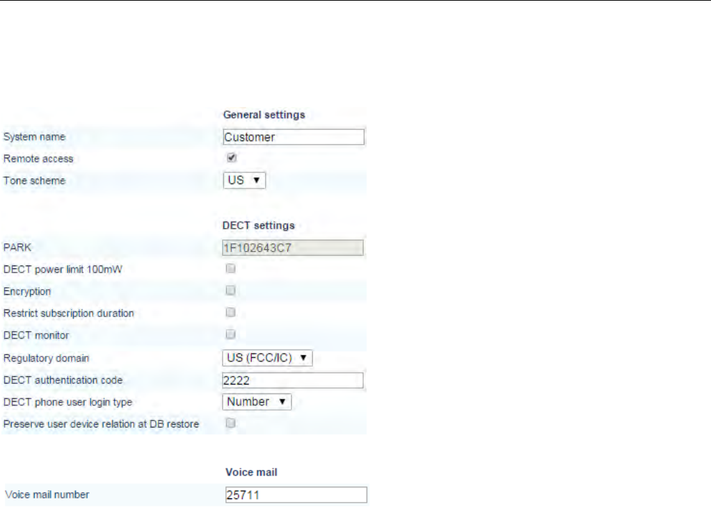
2.3 SYSTEM SETTINGS
The OMM System settings menu provides the basic settings to operate the SIP-DECT system.
System name: Customer Name
Remote access: allow SSH access
Tone Scheme: scheme to simulate call
control tones (country-dependent).
PARK: The system needs a PARK code to
operate. Use the Online PARK service to
obtain a PARK code (see section 4.1.3) (five
or more RFP systems).
Regulatory domain: DECT regulatory
domain applicable to your local region.
DECT authentication code: define as
template for the subscription of new DECT
phones.
Voice mail number: your system voicemail
number. A Mitel 600 phone will then offer the
voice box in the Handset menu.
Getting Started
21
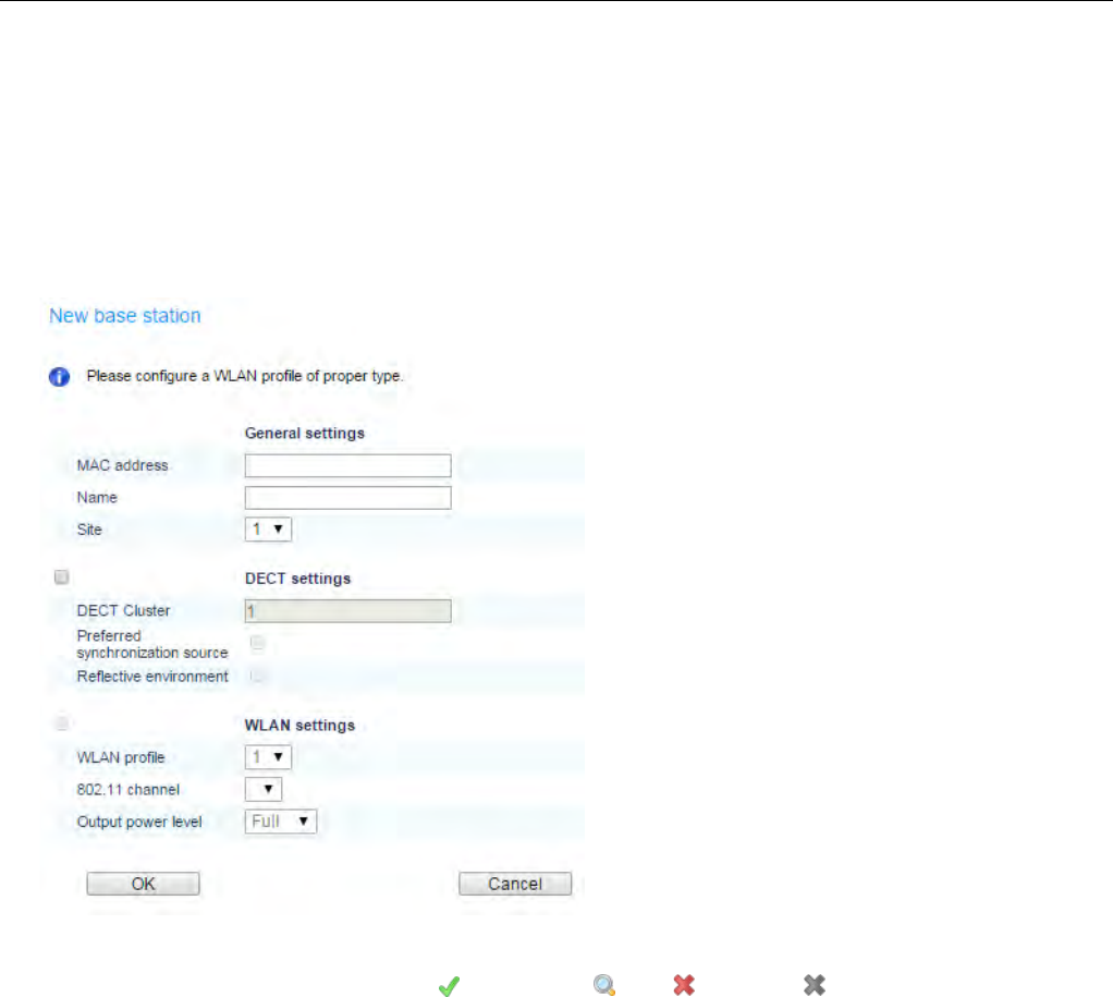
2.4 BASE STATIONS
Configure all base stations (formerly referred to as Radio Fixed Parts) from the Base Stations menu
(including the OMM DECT base stations).
When you click on the Start button below the “Capturing unconfigured DECT base stations” caption, the
OMM lists all DECT base stations trying to connect.
Click on New to configure a new base station.
The base station configuration requires:
- base station MAC address
- Name e.g. location
- Site (default: 1)
- DECT active
- DECT cluster (default: 1)
The Status for each DECT base station is shown in the Base Stations section.
• Active: DECT Radio State (Active , Searching , Off , disabled / - )
• Connected: DECT base station is connected to the OMM, DECT base station must be configured
first.
SIP-DECT OM System Manual
22
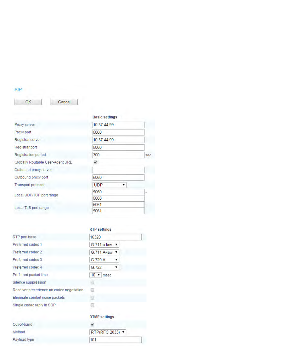
2.5 SIP SETTINGS
Configure the SIP connection to the call server that the OMM must connect to in the OMM System ->
SIP menu. Make sure the Advanced checkbox in the top bar is enabled.
The SIP user account (SIP-ID, Auth, and password) configuration is part of the DECT Phones
configuration.
The default SIP signaling port for SIP-DECT is 5060 / UDP. Change if this is required by the SIP Server.
Enter values for the following:
• Proxy Server : PBX IP or DNS
Name
• Proxy Port: 5060
• Registration Server: PBX IP or
DNS Name
• Registration Port: 5060
Use the default RTP settings unless
your installation requires a different
configuration.
Use the default DTMF settings
unless your installation requires a
different configuration.
Getting Started
23
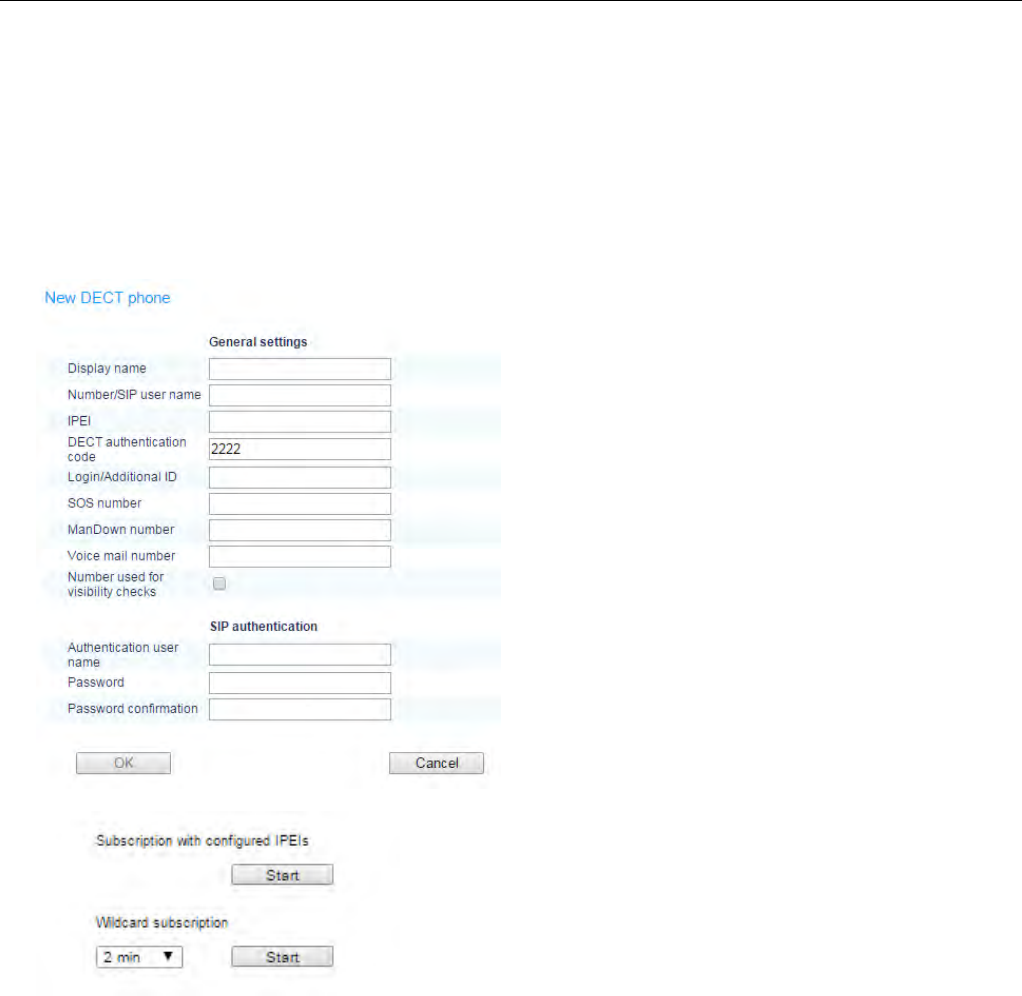
2.6 DECT PHONES
SIP-DECT allows multiple configuration and provisioning methods for DECT phones. In this example we
use fixed DECT phones. A SIP-extension must be configured for each DECT phone (user) on the SIP
call server.
To add a new DECT phone, go to the DECT Phones menu (ensure the Advanced option in the top bar
is enabled) and click New.
Enter values for the following:
Display name: Extension Name
Number/SIP user name: SIP-ID e.g. terminal
phone number
IPEI: Handset hardware identifier (optional)
DECT authentication code: Code for Handset
subscription. If this field is left empty, the system-
wide DECT authentication code is used (see
section 2.3).
Authentication user name: SIP user name
Password: SIP Extension password
To subscribe new DECT phones, subscriptions
must = be permitted by the OMM.
Use Wildcard subscription if no IPEI is set.
To subscribe new Mitel 600 DECT phones, open the DECT phone System > Subscriptions menu.
Select New system and enter the Authentication code provided in your System Settings (e.g. 123456).
The DECT phone prompts you to enter a PARK or to proceed with the subscription without a PARK.
Set the PARK if several DECT systems are around, otherwise the DECT phone tries to subscribe to the
first available DECT system.
SIP-DECT OM System Manual
24
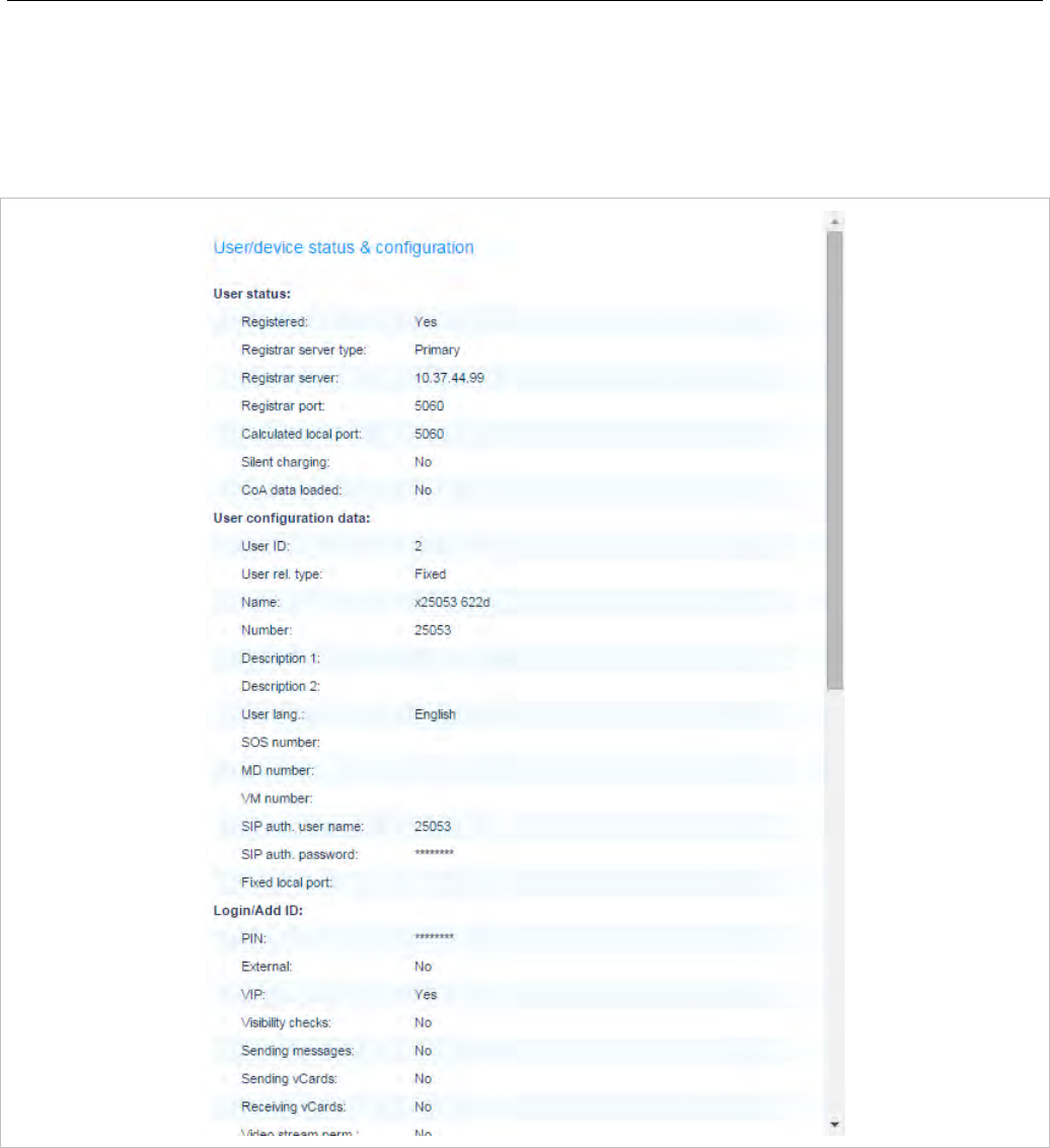
2.6.1 DECT PHONE AND SIP STATE VERIFICATION
You can check the DECT phone state and SIP registration status from the DECT Phones page.
Click on the magnifying glass icon beside the entry for the DECT phone you just created to view details
on the SIP registration status.
Switch the DECT phone off / on to force SIP user registrations.

Enhanced Feature Overview
25
3 ENHANCED FEATURE OVERVIEW
A SIP-DECT system can scale from a small system of five or less DECT base stations to a larger SIP-
DECT system that may include hundreds of DECT base stations. Some of the more advanced features
target larger DECT systems. You may browse the following list of features in order to get an overview
and to decide if it’s relevant for your requirements. You find in-depth explanations in the referenced
sections.
Please note: Be aware that the majority of the new enhanced features require the current
DECT phone firmware release. It is assumed that SIP-DECT installations are configured
to perform an automatic firmware update over the air.
3.1 DOWNLOAD OVER AIR
The Mitel 600 series DECT Phones can download and upgrade their firmware via DECT over the air.
As of SIP-DECT 6.0, the DECT base station software image (iprfp3G.dnld) contains the Mitel 600 DECT
phone software. If the DECT base station houses the OMM, the OMM uses this software to update the
DECT phones. The DECT base station OMM no longer automatically attempts to load a DECT phone
software image from a DECT base station software URL when provided via DHCP or local configuration.
For specific maintenance purposes only, SIP-DECT allows configuration of a URL via the OMM Web
service or OMP to use an alternative DECT phone software image (see section 5.4.1.6). The Mitel 600
DECT phone firmware packages are delivered in the “600.dnld” file for the OMM running on a DECT base
station.
For large installations using a Linux Server-hosted OMM, an RFP software image (iprfp3G.dnld) without
Mitel 600 DECT Phone software is available to reduce network traffic in update scenarios.
The DECT phone firmware packages are included in the OMM installation package for Red Hat
Enterprise Linux (RHEL) and CentOS for the Linux server version of the OMM.
Please note: An RFP upgrade from SIP-DECT 3.0 to 6.0 or later is not supported due to the
extended RFP software image. The 3.0 software does not accept the extended software
image.
For large installations using a Linux Server OMM, the RFP software image (iprfp3G.dnld)
without Mitel 600 DECT Phone software can be used. This software image supports a
direct RFP upgrade from SIP-DECT 3.0 to 6.1.
3.2 WIDEBAND (CAT-IQ 1.0 / MITEL HI-Q™ AUDIO TECHNOLOGY)
Together with the new RFP 35/36/37 IP and RFP 43 WLAN, the Mitel 650 DECT phone can act as a
Mitel Hi-Q audio terminal. This feature is realized using wideband speech according to CAT-iq.
Each Hi-Q connection uses twice the capacity on the DECT air interface, as compared to conventional
narrowband. Therefore, four Hi-Q connections can be established via one RFP, instead of eight
narrowband calls.

SIP-DECT OM System Manual
26
Mitel Hi-Q audio technology must be enabled or disabled per site (see section 5.5). This functionality
must be homogeneously available among synchronous RFPs (members of the same cluster). Each site
with enabled Hi-Q audio must exclusively contain new RFP 35/36/37 IP or RFP 43 WLAN.
Typically one site is identical with one cluster, i.e. all RFPs belonging to a specific site belong to a
specific cluster. However a site can have more than one cluster. The OMM allows configuration of a
cluster that contains multiple sites. Such configuration could annul the rule that Hi-Q audio must be
homogeneously available among synchronous RFPs.
Please note: It is strongly recommended not to setup systems with multiple sites within one
cluster.
3.3 CONFERENCING
To improve the integration with different SIP servers, SIP-DECT includes support for centralized and
internal three-way conferencing.
The centralized conferencing feature is based on RFC 4579 and supports the use of external third party
conference servers (e.g. Broadsoft or Sylantro servers), which are RFC 4579-compliant.
SIP-DECT also includes an integrated conference server implementation based on RFC 4579. The
integrated conference server offers SIP-DECT users who are hosted on SIP servers without their own
conference solution, the opportunity for three-way conferencing.
The centralized as well as the integrated conferencing feature allows users to:
• merge two active calls together into a conference call
• transfer another party into the conference when on an active conference call
• disconnect from an active conference call while allowing the other participants to remain connected
Regardless whether the centralized or the integrated conferencing is used, conferences can be initiated
from the Mitel 600 and Mitel 142d DECT phones.
For a detailed description of conferencing functionality, see section 7.21.
3.3.1 CONFERENCING AUDIO NOTIFICATION
The SIP-DECT Integrated Conference Server (ICS) notifies all conference participants when someone is
joining or leaving the conference. The notification is a specific tone for joining and a specific tone for
leaving the conference.
3.3.2 CENTRALIZED CONFERENCING WITH MIVOICE BUSINESS
SIP-DECT 6.1 introduces support for centralized conferences hosted by the MiVoice Business platform.
The SIP signaling implemented by the MiVoice Business platform require that the SIP-DECT
implementation initiate a conference via blind transfer. The conference mode (External – blind transfer)
can be configured globally for all SIP-DECT users (via the OMP System -> SIP -> Conference tab) or
configured individually for SIP-DECT users (via the OMP DECT Phones -> Users -> Conference tab).
SIP-DECT 6.1 also introduces a new Feature Access Code. The new “Blind transfer” Feature Access
Code allows a user to initiate a SIP blind transfer from the Mitel 600 DECT phone. You can configure the
FAC via the OMM web service (see section 5.9.3) or the OMP (see section 6.12.2).

Enhanced Feature Overview
27
Please note: Overlap sending is not supported for FAC. The blind transfer FAC and the
following transfer target number must be entered en-bloc. The blind transfer FAC cannot
be triggered manually from the dial editor.
To support the integration of SIP-DECT with the MiVoice Business platform, SIP-DECT 6.1 extends the
XML terminal interface for the Mitel 600 DECT phone to include new predefined XML application hooks.
These additional functions can be applied to the DECT phone's programmable keys or accessed from a
menu.
You must configure the appropriate hooks in the OM via the OMM Web service or OMP (System
Features -> XML Applications) to make the applications avialable on the Mitel 600 DECT phones.
3.4 VOIP ENCRYPTION
To allow secured call connections over unsecured IP infrastructures (e.g. internet), SIP-DECT supports
SRTP to encrypt the RTP voice streams and TLS to encrypt the SIP signaling.
These security mechanisms, together with a secured iPBX infrastructure, allow protected call services
and ensure:
• authentication
• integrity
• confidentiality
• privacy
When a Mitel 600 DECT phone user is involved in a SRTP call, a key icon in the call display indicates
that the media path to the next hop is ciphered.
The key icon is only displayed when the connection uses SIP over TLS, SRTP (for 3G RFPs only) and
DECT encryption together for a secure key exchange and a secure media transport.
3.5 DECT ENHANCED SECURITY
In response to market concerns, the DECT standard has introduced improvements to security. Many
security features, which were specified in the DECT standard (respectively GAP) were left optional for
the DECT phones. These mechanisms became mandatory with CAT-iq. Almost all of this functionality
was present and used within SIP-DECT right from the start.
Furthermore, some new features have been added to GAP:
• encryption of all calls (not only voice calls)
• re-keying during a call
• early encryption
Each feature provides an additional security guarantee and is therefore an integral part of the SIP-DECT
solution.
The feature set can be enabled or disabled per site, because enhanced security is available with RFPs
35/36/37/43. Roaming between sites where enhanced security is enabled and disabled respectively
should be avoided.
With SIP-DECT 5.0 and later, when DECT enhanced security is enabled, every connection is encrypted
– not only voice calls, but also service calls (e.g. list access) or messaging.

SIP-DECT OM System Manual
28
Additionally, the cipher key used for encryption during an ongoing call is changed every 60 seconds.
Finally, every connection is encrypted immediately upon establishment to protect the early stages of the
signaling such as dialing or CLIP information.
DECT enhanced security is only supported with Mitel 602 DECT phones. Older terminals (e.g. 6x0d or
142d) or GAP phones still operate as normal, but do not support the new security mechanisms.
3.6 SIP OVER UDP/TCP/TLS
In addition to UDP, SIP-DECT also supports TCP and TLS as transport protocols for SIP signaling. The
OMM provides the following transport protocol modes:
• UDP: all SIP messages are sent/received via UDP
• TCP: all SIP messages are sent/received via TCP
• UDP/TCP: all outgoing connections are always set up via TCP, but incoming SIP messages are also
accepted when sent over UDP
• TLS: all SIP messages are sent/received via TLS connections
• Persistent TLS: all SIP messages are sent/received over TLS connections. The OMM tries to keep
the connection to the SIP server open permanently.
3.7 SIP MULTIPORT
Some call server platforms (e.g. Cisco CUCM) and internet telephony provider environments (SBCs) do
not accept SIP registration from different users who have the same IP address and port, but require a
unique source signaling port for every SIP extension. By default, the OMM uses one source port for all
extensions, but does allow the configuration of individual local signaling ports for users and conference
rooms.
The port range is set per protocol (i.e., UDP/TCP and TLS), and must not overlap with other ports in use.
The following parameters can be configured or read per user (see section 6.10.4) and conference room:
• Fixed port: Port used explicitly for SIP signaling. If set to 0, an automatically calculated port is used
for this user or conference room. The default is 0.
• Calculated port: a read-only parameter whose calculation is based on the internal user or conference
room ID and a configurable port range, in a way that all users or conference rooms are spread over
the range.
The calculation is based on the following rules:
UserPortCount = UserPortRangeStart - UserPortRangeEnd + 1
UserPort = ((UserID – 1) % UserPortCount) + UserPortRangeStart
ConfRoomPortCount = ConfRoomPortRangeStart - ConfRoomPortRangeEnd + 1
ConfRoomPort = (ConfRoomID % ConfRoomPortCount) + ConfRoomPortRangeStart
The “Calculated port” is first updated with the SIP registration of the user or conference room.
Depending on the “Register Traffic Shaping” settings and the number of users/conference rooms, the
update may take some time.
The port ranges used for the port calculation can be configured globally for all SIP DECT users and
conference rooms via the OMP (see section 6.5.4.1).

Enhanced Feature Overview
29
Please note: To provide each user and/or conference room with a unique port using the
port calculation, the port range must be greater than or equal to the number of users or
conference rooms.
Configuration Rules for Port Ranges
Please note the following configuration rules for configuration of the UDP/TCP and TLS port ranges:
• Port ranges for users and conference rooms may not overlap.
• A port range configured outside the defaults (5060, 5061, 4060, 4061) can be within the range
17000 – 32767.
• Port ranges may not overlap with the ports of other OMM services. See section 9.7 for a list of all
ports and protocols.
• If the OMM is running on a DECT base station, the ranges may not include ports used by other DECT
base station protocols. See section 9.7 for a list of all ports and protocols.
• The port range for conference rooms is limited to 100 ports.
• The port range for users is limited to the following:
RFP OMM: maximum 512 ports
Linux Server OMM: maximum 10,000 ports
3.8 MIXED BASE STATION INSTALLATIONS
In sites (or whole systems) with Hi-Q audio disabled, any combination of RFP 32/34 IP / RFP 42 WLAN
and RFP 35/36/37 IP / RFP 43 WLAN is allowed. Note, however, that some security features are not
supported for all DECT base stations (i.e., SRTP is supported on 3G RFPs only, enhanced security is
available with RFPs 35/36/37/43).
RFP SL35 IP support
SIP-DECT supports the RFP SL35 IP after applying the unlock file and the standard SIP-DECT software
to the DECT base station.
Before the standard SIP-DECT software can be installed on the RFP SL35 IP, the unlock.xml file must
be available for the DECT base station on the USB. After applying the unlock.xml file the DECT base
station accepts the standard SIP-DECT software.
In terms of licensing, the OMM manages the RFP SL35 IP with the unlock file and the standard SIP-
DECT software like an RFP 35 IP.
For a detailed description see section 7.30.
3.9 DECT XQ
The DECT radio communication generally suffers from attenuation and radio wave reflection. In
particular, if a building’s walls and ceilings contain a higher portion of metal-based material or if larger
metal surfaces are present, the DECT XQ improves the radio communication between a DECT base
station and a Mitel 600 DECT phone at the expense of DECT channel capacity (see 7.3). Enable this
feature for some or all of your DECT base stations (see section 5.6.3, “DECT settings” or section 6.7.1.2,
“DECT tab”).
DECT XQ audio cannot be combined with Hi-Q audio within the same connection.

SIP-DECT OM System Manual
30
There are three operating modes related to audio quality available on the Mitel 650 DECT phone:
standard audio, Hi-Q audio and automatic.
• In Hi-Q audio mode, a Mitel 650 DECT phone exclusively establishes wideband connections and
does not switch to narrowband later. A Mitel 650 in this mode ignores the XQ capability of the RFP.
• In standard audio mode, a Mitel 650 DECT phone exclusively establishes narrowband connections
and does not switch to wideband later. A Mitel 650 in this mode will switch to DECT XQ and back as
necessary.
• In automatic mode, the connection establishment depends on whether the current base provides
DECT XQ or not. If DECT XQ is available, a narrowband connection will be established. Otherwise a
wideband connection will be established.
3.10 UTF-8 ENCODING
The UTF-8 support allows the presentation of a wider range of language specific characters e.g. umlauts
and eases the internationalization/localization. The OMM and the Mitel 600 DECT phone family support
UTF-8 for text messaging.
Also, the OMM and the Mitel 600 DECT phones support an extended character set for
• User parameter (configurable via WEB, OMP or external user configuration files)
– System name
– User name
– Number
• SIP “display names” und SIP “user id’s” of incoming and outgoing calls
• Call logs
• LDAP directory access
• XML terminal interface objects
For third-party GAP DECT phones, Mitel DECT 142 / Mitel 142d or Mitel 600 with older firmware
releases, the UTF-8 character set is not supported. If possible, the OMM maps UTF-8 character to
LATIN-1.
Please note: The available set of characters is defined by the DECT phone. Please see
/31/. User configuration files must be encoded in UTF-8.
3.11 ALPHANUMERIC DIALING
SIP-DECT supports the dialing of alphanumeric characters. This allows a user to dial names (e.g.
“Heinrich.Mueller”) as well as digits.
If SIP URI dialing such as “name@domain” is used, you must use an (outbound) proxy that supports the
interpretation of SIP user names, including domain names.
Please note: The “Digit treatment” feature handles dialed digit strings only. It cannot be
applied with UTF-8/alphanumeric dialing.
Enhanced Feature Overview
31
3.12 VOICE MAIL NUMBER
A system-wide voice mail number can be configured within the system setting section. This number is
used by the Mitel 600 DECT phone family if a voice box call is initiated.
The system-wide voice mail number can be overruled by a user specific voice mail number.
If there is no voice mail number configured or another type of DECT phone is used; then the voice mail
number must be configured locally in the DECT phone.
Please note: The voice mail number is supported by the external user data configuration
files. The parameter UD_VoiceMailNumber can be set in the user_common.cfg and/or
“user.cfg” or “LoginID.cfg” e.g. “UD_VoiceMailNumber=222”. For details, see the SIP-
DECT DECT Phone Sharing and Provisioning Guide.
3.13 CALL HANDLING
SIP-DECT supports a number of features for enhanced call handling.
3.13.1 DIVERSION INDICATION
The OMM supports the displaying of diversion indications for Mitel 142d and Mitel 600 DECT phones
based on the SIP Diversion Header defined in RFC 5806. This feature is only available with iPBXs
generating such Diversion Headers.
When an outgoing call from a Mitel 142d / Mitel 600 phone is being diverted to another destination (i.e.
via call forward), the phone displays the Caller ID (phone number and/or caller name) of the new
destination and the reason for the call diversion (if delivered from IPBX). Similarly, at the new
destination, the Caller ID of the original call destination is displayed.
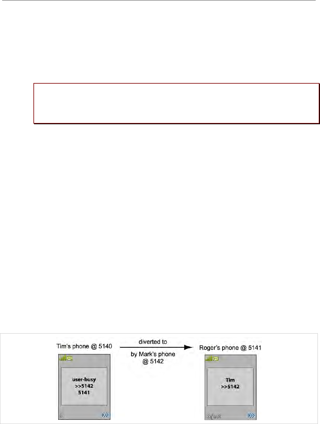
Example:
1 Tim calls Mark at 5142.
2 Mark’s phone is busy and diverts the incoming call to Roger at 5141.
3 Tim’s phone displays the extensions where the call is being diverted to and the reason for diverting
the call.
4 Roger’s phone starts ringing and displays the name and number of the phone the incoming call (Tim)
and the original called destination (5142).

SIP-DECT OM System Manual
32
3.13.2 CALL COMPLETED ELSEWHERE
SIP-DECT supports the SIP “Reason” header field defined in RFC 3326.
When SIP-DECT receives a CANCEL request including a “Reason” header field with “cause=200”, the
incoming call will be marked as accepted in the local incoming call logs of the Mitel 600 and Mitel 142d
phones.
3.13.3 SEMI-ATTENDED TRANSFER
The SIP message sequence for a “Semi-Attended Transfer” allows the transferor to start the transfer
while the target phone is still ringing.
SIP-DECT supports different behaviors for semi-attended transfers. This can be configured on the OMP
SIP -> Advanced settings tab (see section 6.5.4.2).
The supported modes are:
Semi-attended
transfer mode
Refer-to with
replaces
Behavior
Blind No The semi-attended transfer is handled as a blind transfer. The phone
sends CANCEL before REFER for semi-attended transfer.
Blind Yes The semi-attended transfer is handled as a blind transfer. The phone
sends REFER with Replaces for semi-attended transfer and no CANCEL.
This behavior is not SIP compliant but necessary for some iPBX platforms.
Attended - The semi-attended transfer is handled as an attended transfer. Both lines
of the transferor remain active until the transfer succeeds. This behavior is
compliant to RFC 5589.
Please note: The mode “Semi-attended transfer mode: Blind” with “Refer-to with replaces:
yes” is not SIP compliant and should only be used on iPBX platforms that require that
signaling.
3.13.4 THIRD LINE HANDLING FOR MITEL 142D AND 600 DECT PHONES
In earlier implementations of SIP-DECT user call control, a waiting call forces the user to react to that
call (accept or reject), before he can use other supplementary services like call transfer, conference or
inquiry call options.
In the new implementation, a third line is reserved for call waiting purposes. The waiting call is kept in the
background, even if the receiving user decides to finish supplementary services first (see rule at the end
of this subsection). It is also kept, if two lines are already used for brokering (in the former
implementation, the incoming call was answered with busy state). After one of those lines is released,
the waiting call can be accessed by the known means (by R-key or the referring menu options).
Please note: The Third Line Handling is available for Mitel 142d and Mitel 600 DECT
phones, but not for third party GAP phones.
Third Line Handling follows the existing MMI philosophy of the DECT phones. If the user wants to
continue supplementary services when a call comes in:
• R-Key will accept the incoming call. All supplementary services will involve that incoming call
directly or indirectly.

Enhanced Feature Overview
33
• Selecting “Transfer” or “Brokering” offers the possibility to keep the waiting call and continue
supplementary services with the former line only. The waiting call is not involved but can be
accepted later.
Please note: The Third Line Handling feature offers the option to receive a further incoming
call only. A user cannot open a third line as the active part (e.g. to open a further third line
for an inquiry call in a brokering situation, where two lines are already involved).
3.13.5 CALL TRANSFER ENHANCEMENTS FOR MITEL 142D DECT PHONES
The blind transfer has been slightly simplified. The second confirmation after selection of the transfer
targets number by the “start” button is removed. So the steps are reduced to:
• Press I-Key within a basic call
• Select “Transfer”
• Select editor or phonebooks
• Edit or select destination and press “OK”
In earlier OMM releases (SIP-DECT 4.0 and earlier), call transfer had to be initiated via menu. Pressing
the hook key led to the release of the active line and a callback menu popped up.
The OMM now allows the use of the hook key for call transfer, as it is already known from Mitel 600
DECT phones. To enable this feature, the administrator must enable the ”Call Transfer by Hook” feature
in the OMP System -> SIP -> Supplementary Services menu.
To initiate a transfer via the hook key, do the following:
• initiate an inquiry call and dial
• wait for completed connection (optional)
• press the hook key
You can still initiate a transfer via the menu, as before.
If the “transfer by hook” capability is set, the release of the active line in brokering state must be done via
the menu option “Release”:
• Press I-Key within an inquiry call or brokering state
• Select “Release”
3.14 TRUNCATING SIP USER NAME IN SIP URI
If user name info in SIP to-/from-/contact headers or p-asserted-identity is extended by a suffix, which is
separated by a semicolon, this suffix is truncated before the username is printed to call displays or DECT
phone internal call logs.
Example: If the DECT phone receives
Contact: "Dominique B.” sip:5405;openSipsTestproxy@testlab.mitel.randd.com
only 5405 will be extracted as user name to be printed. The display name “Dominique B.” will also be
shown, but the extension “openSipsTestproxy” will be removed.

SIP-DECT OM System Manual
34
To enable this feature, the administrator must set the ”Truncate Caller Identification” parameter in the
OMP System -> SIP -> Supplementary Services menu.
3.15 SYSTEM REDUNDANCY
The SIP-DECT solution offers a number of features to support system robustness and redundancy.
3.15.1 OMM STANDBY
The OMM is the central management entity in a SIP-DECT system and therefore constitutes a single
point of failure. It is possible to automatically transfer the OMM function to a second DECT base station
in case of failure or loss of network connection (see section 7.15).
In an OMM standby implementation, it could happen in rare cases that both OMMs become temporarily
active. In such a situation, all SIP-DECT users are SIP registered from to the configured PBX both
OMMs. This can cause problems if the PBX accepts only one registration per user (non-forking proxy).
To prevent this scenario, SIP-DECT has a mechanism to detect situations with two active OMMs. When
such a situation is detected, the remaining active OMM will SIP re-register all users to the PBX.
This mechanism can be enabled/disabled through the “SIP reRegister after 2 active OMM failover”
parameter in the OMP System -> SIP-> Supplementary Services menu (see section 5.4.3.6)
3.15.2 BACKUP SIP PROXY/REGISTRAR
To increase the operational availability of the system in critical environments like hospitals, the OMM
offers a new failover mechanism for the SIP server. Therefore, in addition to the primary proxy, outbound
proxy and registrar server, it is possible to configure two additional levels of backup servers named
“secondary” and “tertiary” servers (see section 7.20.3).
In addition, a keep-alive mechanism implemented in the OMM allows the automatic failover to
secondary/tertiary servers or automatic coming back to primary servers (see section 7.20.4).
3.15.3 CONFIGURABLE USER ACCOUNT FOR STANDBY CHECK
The “Standby OMM” feature of SIP-DECT allows configuration of the user account to be used to check
the availability of the iPBX. An availability check starts automatically in fail over situations.
The OMM starts a SIP registration for a specific DECT phone user and sends an OPTIONS request to
the configured SIP proxy. If there is an answer, the SIP proxy/registrar is considered reachable and the
standby OMM becomes active.
With previous SIP-DECT releases, the OMM used the user account with the lowest phone number for
the check procedure. To select a specific user account for this purpose, enable the “Used for visibility
checks” flag in the user settings (see section 6.10.4).
Please note: The “Used for visibility checks” flag can only be set for one user. The number
for visibility checks is shown under OMP Status -> Users -> Number menu. If the flag is
not set for a specific user, the OMM uses the user account with the lowest phone number.

Enhanced Feature Overview
35
3.15.4 USER DATA SYNCHRONIZATION (MIVOICE 5000 DUAL HOMING SUPPORT)
SIP-DECT 6.1 introduces support for MiVoice 5000 dual homing, to ensure that SIP-DECT telephony
services survive if the network connection to the OMM goes down. Dual homing is achieved through
user data synchronization across all OMMs in the system. Every peripheral OMM propagates changes in
user, device, Configuration over Air (CoA) profiles or SARI configuration to a central OMM. Every OMM
in the installation (including the central OMM) can use a standby OMM. AXI is used to distribute
configuration changes between the central and peripheral OMMs.
For more information on this feature, see section 7.16.
3.16 DECT BASE STATION SYNCHRONIZATION
To ensure a seamless communication experience, the SIP-DECT system switches an ongoing DECT
phone call from one DECT base station to another if the radio communication quality drops below a
certain threshold. The seamless handover is possible only if the participating DECT base stations are
synchronized. DECT base station synchronization is performed via radio communication between DECT
base stations, which in turn requires a decent radio coverage planning (see section 7.2).
3.16.1 CLUSTERING AND PAGING AREAS
Your SIP-DECT system may include different locations, where the distances between the locations
prevent the RFPs from performing the over-the-air synchronization. In this case, you must split your
network into clusters (or “synchronization domains”). You assign DECT base stations to cluster numbers
for this purpose (see section 5.6.3 “DECT settings” or section 6.7.1.2, “DECT tab”). Note that overlap
between different clusters on one campus or site must be avoided.
If your SIP-DECT system consists of a very large number of DECT base stations, you should configure
the paging area size to optimize the signaling necessary for paging a DECT phone in throughout the
SIP-DECT system (see 6.7.2).
A separate cluster number is also required for a remote site (e.g., for a single DECT base station
servicing an office abroad). Also, if the VPN network connection to the isolated site’s DECT base station
cannot transport DHCP, you may use static IP address configuration for the single DECT base station
(see section 7.6).
3.17 WIRELESS LAN (WLAN)
If you have a number of WLAN RFPs (RFP 42 WLAN or RFP 43 WLAN), the SIP-DECT system also
provides access to your company LAN via Wireless LAN. The RFP 43 WLAN also supports 802.11n.
The WLAN configuration of a group of WLAN RFPs is managed by WLAN profiles (see section 5.8).
3.17.1 802.11I: WPA2-ENTERPRISE PRE-AUTHENTICATION FOR FAST ROAMING
WLAN stations (e.g. laptop) which decide to roam to another WLAN access point (AP) must perform the
full authentication process with the new AP. In 802.1X (RADIUS) networks this can take a long time
resulting in network dropouts during the roam.
The AP share authentication information with other APs, so the station can authenticate faster (pre-auth)
when roaming to a new AP. This method reduces network dropouts significantly.

SIP-DECT OM System Manual
36
The RFP43 automatically enables pre-authentication for WPA-Enterprise enabled WLANs. The RFP 42
does not support this feature.
3.17.2 CHANNEL CONFIGURATION FEEDBACK FOR HT40 AND TX POWER
The HT40 channel configuration in 802.11n enabled networks may not always become active because of
other access points that use channels that would overlap. In this case, the RFP43 falls back to HT20.
From SIP-DECT 5.0 on, the effective channel configuration and the transmit power are reported to the
OpenMobility Manager.
You can view these parameters in the OMM Web service and the OMP (DECT base stations > Device
list -> Show details – WLAN tab) and change the channel to a frequency without overlapping APs.
3.18 PC-BASED OMM INSTALLATION
A very large number of DECT base stations or a large number of DECT phones may exceed the storage
capacity or processing power of the embedded DECT base station. For this reason, it is also possible to
operate the OMM on a standard PC under the Linux operating system (see section 7.12).
As of SIP-DECT 5.0, CentOS 6 and Virtualized environments (based on VMWare ESXI 5.5.0) are also
supported. SIP-DECT 6.1 has been tested with CentOS 6.x.
3.19 OM LOCATING APPLICATION
You can set up a system to locate and track DECT phones in your DECT system. This includes a
separate Web user interface, which for example can be operated by service personnel to locate a DECT
phone that has triggered an alarm. Refer to the OpenMobility Locating Application User Guide for details
(see /27/).
The OM Locating application can display small maps showing the placement of a DECT base station. In
earlier SIP-DECT releases, these graphic maps had to be generated manually by using a graphic editing
program.
The OM Management Portal (OMP) can be used to generate the graphic map images needed by the OM
Locating application.
Images showing the floor plan of the buildings belonging to the OM system can be imported into the
OMP. In a next step the RFPs of the SIP-DECT system can be placed on these images with drag and
drop. Finally for each of the RFPs, the graphic map images will be generated in the format and size as
required by the OM Locating application.
The process and the OMP functionality for this feature are described in detail in section 7.23.
3.20 VIDEO SUPPORT
The SIP-DECT solution supports snapshot images and video streaming via USB video devices
connected to DECT base stations.
Enhanced Feature Overview
37
3.20.1 USB VIDEO DEVICES
You can configure and use USB video devices that are fully supported by the UVC video class device
driver. The USB video device is connected to the USB port of one of the SIP-DECT RFPs 35 / 36 / 37 /
43. A valid locating license is also required. In conjunction with the “Surveillance” feature of the OM
Locating application, the USB video devices generate snapshot images and video streams.
For a detailed description see section 7.27.
One USB camera (only the types Logitech HD Webcam C615 or Logitech HD Pro Webcam C920) can
directly be connected to a SIP-DECT RFP 35/43. Such cameras are used as well with the OM Locating
Application as with the Terminal Video feature.
3.20.2 TERMINAL VIDEO
With SIP-DECT 5.0 and later, the Mitel 600 DECT phones support video streams from cameras
connected to SIP-DECT base stations RFP 35/43. When a user has the video stream permission, he can
choose in the system menu from a list of cameras to connect.
Video Streaming is only available when the DECT phone is connected to a RFP 35/36/37/43 and the
permission is set for the site and the DECT phone.

SIP-DECT OM System Manual
38
Video streams are treated like a call by the DECT phone, and require two (of eight) air channels on the
RFP for each stream. The DECT phone can also perform handover between RFPs with an active video
connection.
A video connection is automatically terminated by the system in case that any related capability (e.g.
video stream permission) is changed.
The maximum number of simultaneous terminal video streams per camera is restricted to 10.
Connection and configuration of cameras is similar to the steps for the locating application. Special steps
necessary for terminal video are:
• Enable all sites that have the technical capability (only RFP 35/36/37/43) via OMP for terminal
video.
• Enable the additional service “Video stream permission” via OMP (DECT Phones -> Users) for
those users who are allowed to use this feature.
Please note: It is strongly recommended to set the radio fixed parts attributes building, floor
and room, if you configure a huge system with a large number of cameras. This will ease
the selection of cameras on the DECT phone menu.
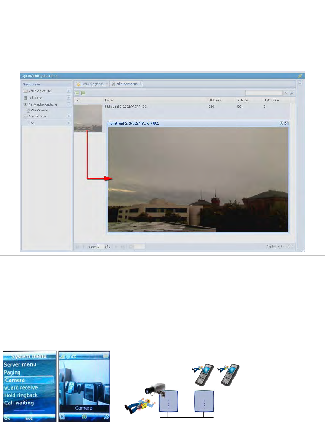
A video camera must be configured in OMP before it can be offered to applications and the Mitel 602
DECT phones.
The selection of the menu “Cameras” is offered in the Mitel 600 DECT phone “System menu” (e.g. long
press on Menu >>>), if
• at least one camera is plugged and activated by the enable flag
• the DECT phone user has the permission to select cameras
• the DECT phone is located within a site, which allows terminal video
Navigation within the camera menu will be done by OK (and ESC) keys. To establish a video stream,
press “hook off” if the name of your camera is selected.
If the number of cameras exceeds the visible lines of the DECT phones display, the presentation is
arranged hierarchically. In this case, at least one sublevel must be selected before camera names are
offered. The hierarchy of the referenced DECT base station (site, building, etc) is inherited for that
purpose.
The destination of a video call is added to the DECT phone internal redial list.
Please note: Audio calls or any system service activities are not possible during an
established video link. Any kind of auto callback (initiated by a message or pushed by
XML notification to direct dial) is not supported for video calls.
3.21 MITEL 600 DECT PHONE DIAL EDITOR MODE
It is assumed that most customers use digits only in their dialing plan, and that it is more convenient if
dial editors support only the digits 0 to 9, * and #. The Dial editor supports digits only flag (on the
OMP (System -> Advanced settings -> DECT Phones tab) enables this mode. In this mode, the * has
the meaning of a digit to be merely dialed, even if it short-pressed.
If the mode is not set to digits only, the short pressed * will change the editor mode to alphanumeric.
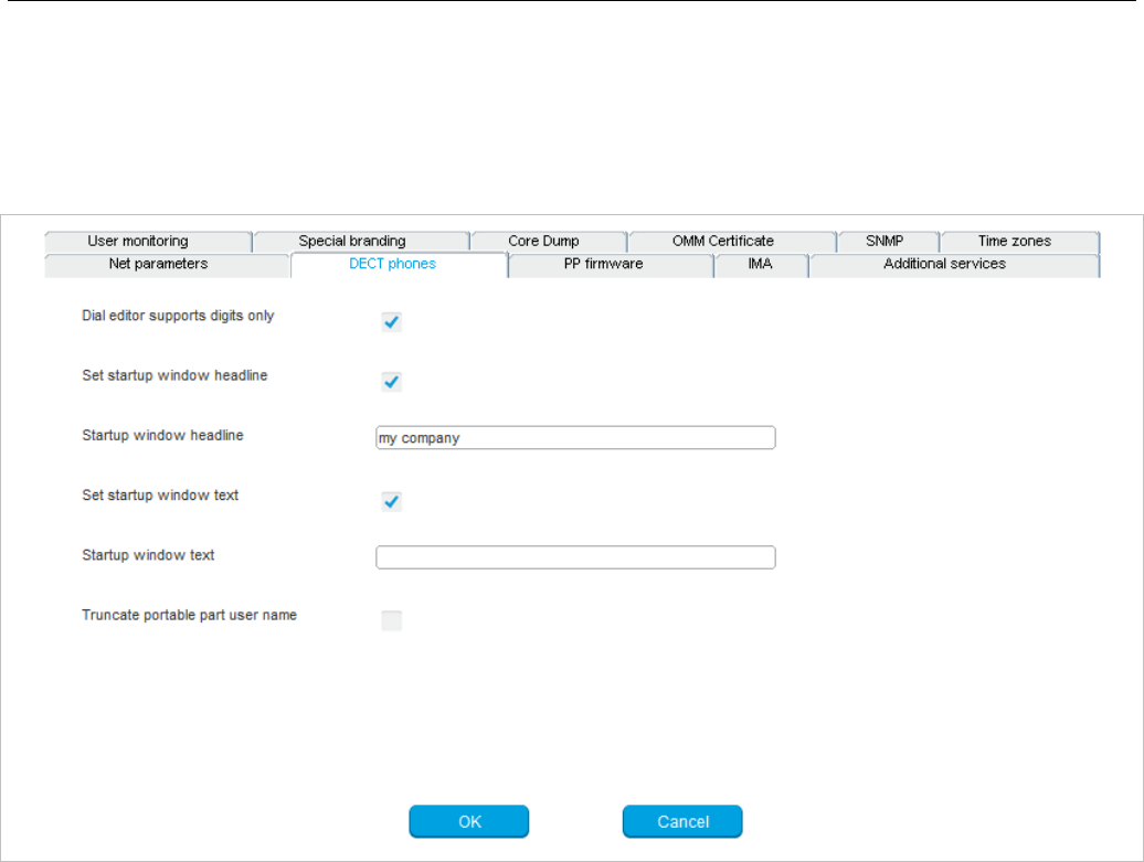
Enhanced Feature Overview
39
3.22 MITEL 602 DECT PHONE CUSTOMIZABLE BOOT TEXTS
By default, the text shown on the Mitel 600 DECT phone at start up is Mitel-specific (branded in the
firmware). Customers can also define their own text. See the screenshot below from the OMP (System -
> Advanced settings -> DECT Phones tab) as an example:
• Startup window headline is set to “my company” and activated by the Set startup window
headline flag
• Startup window text is set to an empty string. As a consequence, there will be no startup text on the
DECT phone
3.23 EXTENDED MESSAGING
You can set up an extended messaging and alarms system (e.g. to provide automated reactions on
alarms triggered by DECT phones or on alert messages). The extended messaging system may also
provide message-based services, and may also be integrated with external computer systems. See the
OpenMobility Integrated Messaging & Alerting User Guide for details.
3.24 OPENMOBILITY DECT PHONE PROVISIONING
While some users in the SIP-DECT system use a dedicated DECT phone, it is also possible to operate
shared DECT phones. The OpenMobility SIP-DECT solution provides an enhanced DECT phone
sharing and provisioning concept that enables the management of a large number of DECT phones and
provides a flexible subscription model.

SIP-DECT OM System Manual
40
The SIP-DECT system allows logging into and out of different DECT phones with a personalized user
account, import of user data from an external provisioning server, automatic subscription of new DECT
phones, and control of subscription-specific system functions from DECT phones.
See the SIP-DECT DECT Phone Sharing and Provisioning Guide for details on this feature.
3.25 USER MONITORING
The OMM monitors the status of the user’s DECT phone to verify the user’s availability to receive calls or
messages. By default, passive and active user monitoring is disabled.
In addition to the standard request, response and notification messages, the OMM generates alarm
triggers if a user becomes unavailable. The alarm triggers can be consumed by the OM IMA, the OM
Locating application, or another application using OM AXI. If a user becomes available again, the OMM
sends an additional alarm trigger to indicate the change in status.
User status information is available via OM AXI and OMP.
For a detailed description of the “User monitoring” feature see section 7.29.
3.26 SIP-DECT XML TERMINAL INTERFACE
The SIP-DECT XML terminal interface allows external applications to provide content for the user on the
DECT phones display and much more. The list of potential applications is endless. The interface is
derived from the XML API for Mitel SIP Phones and coexists with the OM AXI features e.g. text
messaging.
Partners can get access to the interface specification /37/ by registering for the A2P2 program.
To call a certain URI there are a number of hooks available for the Mitel 600 DECT phones which can be
put on a programmable key or can be called from a menu. You can activate the predefined XML hooks
via the OMM Web service (see section 5.9.4) or the OMP (see section 6.12.6).
You can also activate the XML hooks through the Configuration over Air (CoA) feature; see section 7.23
for more information.
Please note: From SIP-DECT release 3.1 on, behavior for XML objects has been added or
changed (see SIP-DECT XML terminal interface specifications “PA-001008-05-00” and
“req-0715” (version 0.21) for more details).
3.26.1 FEATURE ACCESS CODES TRANSLATION
Many PBXs allow the control of PBX supplementary services by dialing specific numbers called feature
access codes (FAC).
SIP-DECT supports the XML application “Feature Access Codes Translation” to avoid any conflict to
SIP-DECT feature access codes or digit treatment rules with PBX feature access codes.
If “Feature Access Codes Translation” is activated, SIP-DECT users can chose “FAC” menu on the
Mitel 600 or Mitel 142d DECT phones in any call state and enter the feature code en-bloc. The input is
sent to the PBX (Application server) within a URI request.
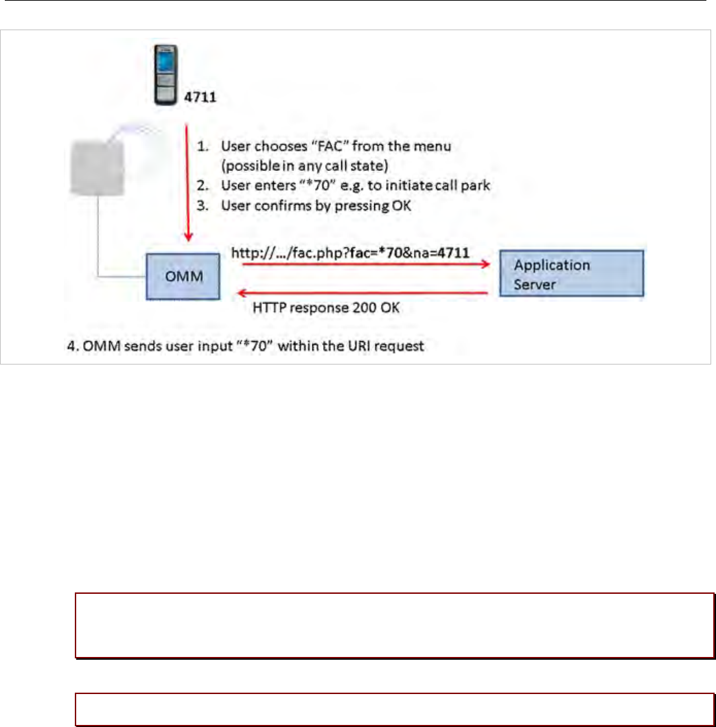
Enhanced Feature Overview
41
This feature can be configured using OMP on the XML applications page (see section 6.12.6).
3.26.2 RING TONE SELECTION FOR (ALARM) MESSAGES
This feature extends the capability to set ringer tones to provide an acoustic signal to the receiver of a
message and is related to messaging configuration and management function described in the OM
Application XML Interface Specification.
In previous SIP-DECT releases, the “melody” field offered ten tones, selected by an identifier. In the
current release, the “explicitToneSelection” field allows the user to select a tone, which does not have to
belong to the set of “melody” tones, by the name string. If both are set, the explicitToneSelection value
takes precedence.
IMPORTANT : Depending on the DECT phone model, not all strings may work. The
string value is not checked for correctness. Invalid or unknown string values are
ignored.
Please note: The OM Message & Alerting License is required to use these features.
3.27 CENTRAL DECT PHONE CONFIGURATION OVER AIR (COA)
SIP-DECT 6.0 and later supports centralized DECT phone configuration over the air (CoA) for Mitel 602
DECT phones. DECT phone CoA is useful for deployment of special configuration to a single DECT
phone or a large number of DECT phones. No local access to the DECT phone is required.
DECT phone CoA is implemented by providing additional configuration information to the well-known
configuration files or providing profiles via OMP. Configuration can be changed at the device level
(DECT subscription) or the user level (based on login).
Configuration of all DECT phones with a predefined default profile is also supported. Up to 20 possible
DECT phone profiles make it easy to adapt to different usage scenarios for heterogeneous user groups

SIP-DECT OM System Manual
42
(e.g., nurses and doctors in hospital environments). See section 7.23 for more information on this
feature.
3.27.1 COA ENHANCEMENTS
The Mitel 602 DECT phone 6.1 firmware (bundled with SIP-DECT release 6.1) includes new features
which are configurable via Configuration over Air (CoA).
New configuration commands allow you to overwrite local key programming on the Mitel 602 DECT
phones. SIP-DECT 6.1 also supports configuration of the new XML application hooks introduced for the
XML terminal interface via CoA (see section 3.26).
In addition, the Mitel 602 DECT phone 6.1 firmware introduces variable lists. A variable list includes
a number of items, each of which corresponds to an action to be performed on the DECT phone. For
more information, see section 7.23.5.
3.28 INTEGRATION OF CORPORATE DIRECTORIES
The SIP-DECT solution supports integration of LDAP and XML-based corporate directory services. XML-
based directory services can be implemented using the XML terminal interface. The configured
directories are presented in a list on the Mitel 600 DECT phone if the user calls up the central directory.
For configuration information see section 6.12.5.
3.29 INTEGRATION INTO EXTERNAL MANAGEMENT SYSTEMS
You can use the following features to integrate the SIP-DECT system into external management
systems:
• Each DECT base station may run an SNMP agent that can be queried by SNMP management
software (see 7.19).
• To further integrate into external configuration management systems, the DECT system’s
configuration is available my means of ASCII-based configuration files. You can configure automatic
import of configuration files from an external server. For more information, see section 7.8.
• The OM AXI software application interface can also be used for integration into external systems.
Refer to the OM Application XML Interface (OM AXI) specification, see /31/.
3.30 SYSTEM CONFIGURATION TOOLS
You can configure and maintain the SIP-DECT system with two different applications:
• the Web-based OMM Web service (see section 5)
• the Java-based OM Management Portal (OMP, see section 6)
Both applications support the essential configuration and administration settings required for smaller
SIP-DECT systems. However, for larger SIP-DECT systems using enhanced features, some settings are
only available in the OMP application.

Enhanced Feature Overview
43
The following table lists the features and settings that are available in each configuration tool:
Feature Web OMP
SNMP configuration Yes Yes
DB management: User data import No Yes
Configuration and start of a system dump Yes Yes
Download system dump to PC No Yes
Event information display (Event log) Yes Yes
WLAN profile configuration Yes Yes
Dynamic DECT phone subscriptions (OpenMobility provisioning) No Yes
Locating settings for DECT phone No Yes
Paging areas No Yes
Alarm Triggers No Yes
DECT base station sync. View No Yes
DECT base station statistics No Yes
DECT base station data export No Yes
Capturing unconfigured DECT base stations Yes Yes
Configuration of XML applications (SIP-DECT XML terminal interface) Yes Yes
Configuration of SIP backup servers No Yes
User monitoring No Yes
3.31 SIMPLIFIED LICENSING
With SIP-DECT 6.0 or later, the licensing model is simplified. The system no longer distinguishes
between different DECT base station “soft-brands”, and some licenses are deprecated. See section 4 for
more information.
Please note: New license files are not compatible with SIP-DECT 4.0 (or older) systems.
3.32 EXTENDED REGULATORY DOMAIN SUPPORT
SIP-DECT 6.1 enables operation of the SIP-DECT solution in more countries. The SIP-DECT system
can be operated in all countries that allow operation of DECT devices with frequency bands and transmit
power settings supported by the current SIP DECT phones and base stations. In most cases, this
requires different frequency channel and transmit power settings.
This feature is intended mainly for installations on cruise liners, where the SIP-DECT system requires a
switch of regulatory domain depending on the actual location of the ship. Such systems are planned and
installed based on a site survey with 100mW transmit power. The lower transmit power value is used at
all times, independent from the regulatory domain.

SIP-DECT OM System Manual
44
A new regulatory domain, 1910-1927MHz_250mW, has been added for South America. You can
configure this regulatory domain via the OMP (System -> Basic settings -> DECT tab); see section
6.5.1.2 for configuration details.
In addition, a new parameter is introduced to limit the DECT base station transmit power to 100mW,
independent of the active regulatory domain. The active transmit power is sent to the DECT phone when
it registers its location with the OMM. The DECT phone adjusts its transmit power to the value received
from the OMM.
3.33 DECT BASE STATION RESET TO FACTORY SETTINGS
A DECT base station can be reset to factory settings using a USB flash drive with a file on it named
“factoryReset”. When the USB flash drive is plugged into the DECT base station, the DECT base station
is reset to factory settings automatically. The file is automatically removed from the USB flash drive
during this process.
You can also reset the base station to default settings using the OM Configurator or the OMM Web
service (see section 7.7.8).
3.34 SIP ENHANCEMENTS
With SIP-DECT 6.0 and later, the SIP-DECT solution provides several enhancements to the SIP protocol
implementation.
3.34.1 GLOBALLY ROUTABLE USER-AGENT URIS (GRUUS)
Globally Routable User-Agent URIs (GRUUs) provide a way for anyone on the Internet to route a call to
a specific instance of a SIP User-Agent. IP-DECT provides GRUU support according to RFC 5627.
A “sip.instance” is added to all non-GRUU contacts. You can enable or disable this support via OMP or
Web service (System -> SIP -> Basic Settings).
3.34.2 SESSION TIMER
SIP-DECT supports RFC4028 “Session Timers in the Session Initiation Protocol (SIP)” to keep call
sessions alive and to determine whether established call sessions are still alive.
You can configure the session refresh period via OMP or Web service (System -> SIP -> Advanced
Settings).
3.34.3 SIP CONTACT MATCHING
In special Network Address Translation (NAT) environments, the Contact URI in a SIP response to a
REGISTER request may not match the URI originally sent out.
In such cases, SIP-DECT offers the “SIP contact matching” configuration parameter. You can enable this
parameter via OMP or Web service (System -> SIP -> Advanced Settings).
3.34.4 CONFIGURABLE CALL REJECT STATE CODES
The SIP status codes for user-rejected calls and device-unreachable calls are configurable via OMP and
Web service (System -> SIP -> Advanced Settings).

Enhanced Feature Overview
45
3.34.5 CALL RELEASE TIMERS
SIP-DECT 6.0 or later allows changing certain system default timers. These timers determine the DECT
phone call behavior when calls are released by the B party.
You can configure the ”Call release timeout”, ”Hold call release timeout”, and ”Failed call release
timeout” parameters via OMP or Web service (System -> SIP -> Supplementary Services).
3.34.6 INCOMING CALL TIMEOUT
Incoming calls are automatically rejected when the user does not answer the call within 180 seconds.
This time period is too short for special customer use cases.
You can configure this interval through the “Incoming call timeout” parameter via OMP or Web service
(System -> SIP -> Advanced Settings).
3.35 AUTO ANSWER, INTERCOM CALLS AND AUDIO SETTINGS
Certain call features force the DECT phone to call a specified SIP user automatically and, as an option,
to establish a speech path immediately without any intervention by the DECT phone user.
SIP-DECT allows control of the following audio settings on the DECT phone to prevent unauthorized
parties from hearing the call:
• Speech path can be initially set to be muted
• A warning tone may be generated
SIP-DECT also supports intercom calls. This means that the originating party can force the called party’s
phone to establish a speech path immediately. Control of the same audio settings applies.
3.35.1 INTERCOM CALLS
A DECT phone can be forced to answer an incoming SIP call automatically if certain information is
included in the SIP header. A DECT phone user can also initiate an intercom call, which automatically
triggers the destination to talk.
Intercom calls can interrupt active calls (“barge in”). If it is an established basic call, the active call is put
on hold. In more complex call situations, a “barge in” always supercedes existing active calls, unless the
active call is a “SOS” call.
The call is identified as an intercom call if the SIP INVITE header includes:
• a “Call-Info” header containing “answer-after=0”
• an “Alert-Info” header containing “info=alert-autoanswer”
Please note: This feature is only available for Mitel 600 DECT Phones, version 4.0 or
higher.
3.35.1.1 Barge-in of incoming intercom call
If a “barge in” action on an existing call is necessary, note the following rules about the treatment of
existing active calls:
• If the user is in a basic call (one line already active) or is brokering (two lines are used), the active line
is placed on hold and kept in the background. No line is released.

SIP-DECT OM System Manual
46
• Incoming ringing calls which are not yet connected are converted to waiting calls.
• If a third line is open due to a waiting call, that call is released and the line is replaced by the intercom
call.
• Outgoing calls that have not yet been answered and are in a dialing state, are released.
• If a call is on hold by the B party, the call is released. An on-hold by the B party is difficult to maintain
while another line has an active audio stream.
Normally, the user should be able to resume the interrupted calls again when the intercom call is
finished. However, the calls may fail if several maintained lines collide with call exceptions (e.g., a failed
call transfer that was maintained in the background).
Please note: Barge-in is rejected if the DECT phone is part of a SOS/alarm call.
3.35.1.2 Outgoing intercom calls
A DECT phone can initiate an intercom call. The user must dial the configured access code, followed by
the destination’s user id / number.
If a DECT phone generates an intercom call, an Alert-Info header is added to the SIP INVITE:
• the “Alert-Info” header contains “<http://x>info=alert-autoanswer”
3.35.2 AUTO ANSWER AUDIO SETTINGS
You can configure global auto-answer settings through the OMM Web service or the OMP. Global
settings are valid for all DECT phone users in the system, except users who have individual settings.
Incoming call settings:
• Auto answer allowed (default: true)
• Microphone mute (default: true)
• Warning tone (default: true). A short ringtone is played if there are no active calls. If there is an active
call in a “barge in” situation, the ringing will be in-band.
• Allow barge in (default: true)
Outgoing call setting:
• Dial prefix (default: string is empty). Empty string means that an intercom call cannot be initiated by a
DECT phone.
3.35.2.1 User-specific incoming call setting
You can set user-specific settings via OMP, but not the OMM Web Service. Default values for all
parameters are inherited from global settings.
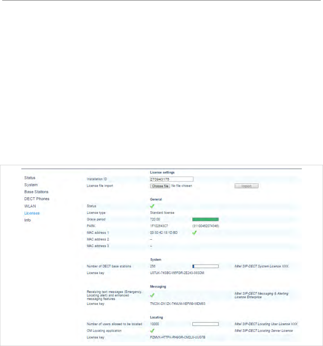
Licensing
47
4 LICENSING
4.1 LICENSING MODEL
Licenses are required based on the SIP-DECT system size and feature set. Licensed features include:
• the number of configured DECT base stations
• the Messaging application
• the Locating application
For information on the messaging and locating applications see the appropriate documents listed in the
References section (section 9.11).
Note: A license to upgrade the SIP-DECT software to a SIP-DECT 6.0
or later is no longer required.
The License settings page in the OMM Web Service provides a summary of the SIP-DECT licenses
installed.
4.1.1 SYSTEM LICENSES
To properly address small, medium and large installations, the SIP-DECT offering is split into the
following categories, according to system size.
Note: As of SIP-DECT 6.0, no distinction is made between DECT base
station brands. License and feature rules apply equally to all
DECT base station types (standard RFP, L-RFP). Only the DECT
base station hardware determines available functionality.

SIP-DECT OM System Manual
48
Small systems – 1 .. 5 DECT base stations
• No license required
• Telephony and basic messaging only
• No locating or enhanced messaging functionality
• PARK code for up to 256 DECT base stations required for operation (provided by the online PARK
service)
Note: Existing SIP-DECT systems with up to five L-RFPs are
automatically migrated to the integrated license model. Larger
systems still require a valid license file.
Medium systems – up to 256 DECT base stations (minimum 3 DECT base stations)
• OM System License required for the number of DECT base stations (10, 20, 50, 100, etc)
• Licenses for Messaging and Locating can be added
• PARK code for 256 DECT base stations included in license file
Large systems – up to 4,096 DECT base stations
• OM System License required for the number of DECT base stations
• OpenMobility Manager (core software) resides on one or two Linux-based PCs
• Licenses for Enhanced Messaging and Locating can be added
• PARK code for 4096 DECT base stations included
Note: With SIP-DECT Release 6.0 or later, there is no longer a
demonstration mode for the OMM.
4.1.2 ABOUT G.729 CHANNELS
With SIP-DECT Release 6.0 or later, the number of G.729 channels is no longer limited to a specific
fixed number or license. The number of G.729 channels depends only on the resources available (i.e.,
DECT base station capacity and number of base stations).
4.1.3 PARK SERVICE
A Portable Access Rights Key (PARK) is required to operate a SIP-DECT system with up to five DECT
base stations. (For systems with more than five DECT base stations, the generated license file contains
the PARK code). With SIP-DECT 6.0 or later, the PARK code is provided via a centralized Web service;
you do not need to enter the code manually (as in earlier SIP-DECT releases). A PARK for up to 256
DECT base stations is available upon request from the OMM Web service.
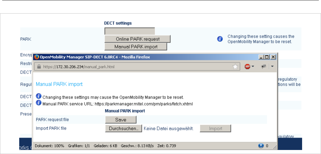
Licensing
49
You must have an internet connection to access the online PARK service. If no internet connection is
available, you can download a PARK request file from the OMM (PARK service URL is
https://parkmanager.mitel.com/pm/parks/fetch.xhtml) and upload it to the PARK server from a computer
that is connected to the Internet. You can then import the file into the OMM.
If you have a valid license file that includes a PARK, this mechanism is not necessary.
4.1.4 UPGRADE LICENSE
With SIP-DECT Release 6.0 or later, you do not require a license to upgrade to a newer release.
Older systems with an OM Activation License for L-RFPs (3..20 RFP-L) require a license upgrade, which
is available from the License server at no cost. Note that you must already have three MAC addresses
registered on the license server for the license upgrade.
4.1.5 GRACE PERIOD
The OMM identifies medium and large systems using the unique PARK as well as the MAC addresses of
up to three DECT base stations (called validation RFPs here).
Three DECT base stations guarantee redundancy when a hardware or network error occurs. An odd
number of DECT base stations prevents system duplication by splitting the system into two separate
parts.
When the first validation DECT base station is disconnected, the OMM generates a warning and displays
the message on the Status page of the OM Web service (see also section 5.3).
If the second validation DECT base station is disconnected, the OMM treats it as a license violation, and
starts the timer on a 30-day grace period. When the timer expires, the OMM restricts all licensed
features.
When the validation DECT base stations are reconnected to the OMM, the grace period is incremented
until it reaches its maximum of 30 days.

SIP-DECT OM System Manual
50
4.1.6 LICENSE VIOLATIONS AND RESTRICTIONS
A license can be violated in three ways:
• The number of configured items exceeds the number of licensed items. In this case the associated
feature is restricted:
- the audio stream of calls is dropped after 30 seconds when the number of connected DECT base
stations exceeds the licensed number
- the messaging application limits the type of messages to “info”, “low”, “normal” and “high”
- the locating feature is stopped
• For SIP-DECT 5.0 (or older) systems, the software version in the license file does not match the
software version running on the OMM.
• The OMM has no connection to at least two of the validation DECT base stations and the grace
period has expired.
The restrictions above are in place until at least two validation DECT base stations are reconnected to
the OMM.
4.2 UPLOADING A LICENSE FILE
A license file must be generated on the Mitel license server. The license confirmation provided when you
order your system contains detailed information on how to generate the license file. The file can be
uploaded into the OMM either via Web service (see section 5.10) or via the OMP (see section 6.12.6).
A license file contains a PARK for system identification. If the newly imported PARK differs from the
current PARK, the OMM performs a restart. In this case, all existing DECT phone subscriptions will be
deleted.
Note: The file can be opened with a text editor to view the license or
activation parameter.
The license file includes an installation ID. This ID prevents the administrator from loading the wrong
license file with a different PARK (resulting in all DECT phones being unsubscribed). The download page
for the license file displays the installation ID. If no Installation ID is configured (value 0, which is the
default), the ID is automatically set while loading the license file. If the ID does not fit to the license file,
the license file import will fail. The installation ID does not change when you load a new license file from
the license server, unless the PARK has changed.

Licensing
51
The SIP-DECT license file format prepares the system for receiving licenses from Mitel PBXs or to act as
a license key server for other Mitel products in future releases.
Please note: New license files (as of SIP-DECT 5.0) are not compatible with previous
versions of SIP-DECT systems (SIP –DECT 2.1 – 4.0).
4.3 LICENSE MODELS
4.3.1 SMALL SYSTEM (UNLICENSED)
When changing the PARK on the System settings page of the OM Web service, the OMM uses the
built-in license resp. the standard license for a small system.
The built-in license for small system features:
• up to five DECT base stations
- standard telephony
- sending messages from DECT phones for all users
- no locating
• Messaging features are generally restricted to type “Info”, “Low”, “Normal” and “High” for all users (no
“Emergency” and no “Locating Alert”).
When there are more than five DECT base stations configured, only the first five base stations stay in
the configuration database. All other base stations are dropped silently.
4.3.2 MEDIUM OR LARGE SYSTEM
When the PARK is set through the upload of a license file, the OMM enters the licensed state. In this
state the OMM uses the following license features coded into the license file.
• System license (Medium):
- three and up to 256 base stations
• System license (Large):
- three and up to 4096 base stations
- software version of the OMM allowed to be executed
• Messaging license:
- whether clients are allowed to receive alarm messages or have enhanced messaging options
• Locating license:
- number of locatable DECT phones
- whether the locating application is allowed to execute
When you generate a license file from the license server, you must enter the MAC address of three base
stations. These three validation base stations are used to operate the grace period as described in
section 4.1.5.
When obtaining the license file from the license server, it is possible to use the PARK used for a small or
medium system installation. This prevents the need to re-subscribe all DECT phones.
Note: As of SIP-DECT 6.0, the PARK can no longer be changed
manually on the System settings page of the OM Web service.
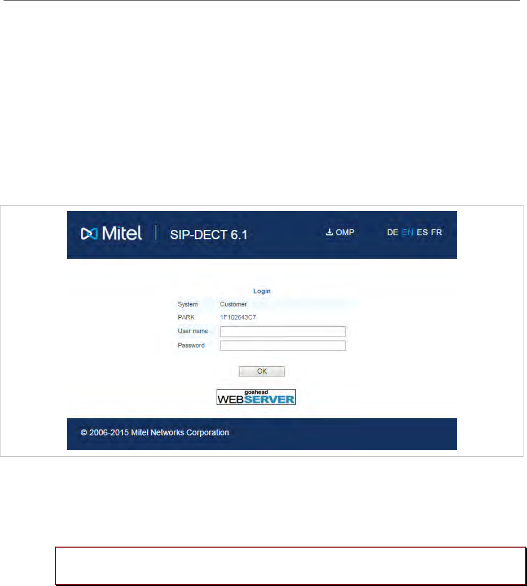
SIP-DECT OM System Manual
52
5 OMM WEB SERVICE
The OMM acts as an HTTP/HTTPS server. The HTTP server binds to port 80 and HTTPS binds to port
443 by default. A HTTP request on port 80 will be redirected to HTTPS on port 443.
5.1 LOGIN
The OMM allows more than one user at a time to configure the system. A user must authenticate with a
user name and a password. Both strings are case-sensitive.
With initial installation, or after discarding all settings, the OMM Web service is accessible via a default
built-in user account with user “omm” and password “omm”.
With the first login to a new SIP-DECT software version, the user must accept the End User License
Agreement (EULA) (see section 5.11).
If the default built-in user account is active, the administrator must change the default account data
(passwords) of the “Full access” and “root” account. The meaning of the different account types is
described in section 7.17.1.
Please note: The OMM forces a change to the default account data. As long as the
passwords are unchanged, the OMM will not allow any other configuration.
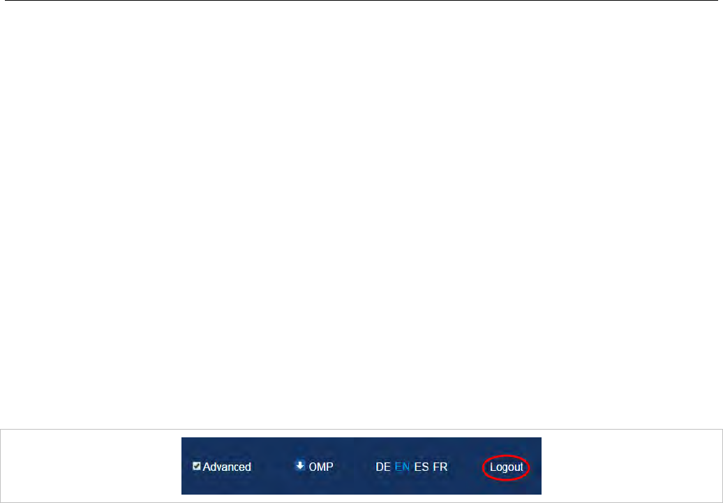
OMM Web Service
53
After login in, the following menus are available (with the Advanced option enabled in the top bar):
• Status menu: displays the system status (see section 5.3).
• System menu: allows configuration of general SIP-DECT system parameters (see section 5.4).
• Sites menu: allows grouping of DECT base stations into different sites (see section 5.5).
• Base Stations menu: allows configuration and administration of the attached base stations (see
section 5.6).
• DECT Phones menu: allows administration of the DECT phones (see section 5.7).
• WLAN menu: allows configuration of WLAN parameters (see section 5.8).
• System Features menu: allows administration of system features like digit treatment and directory
(see section 5.9).
• Licenses menu: allows administration of licenses (see section 5.10).
• Info menu: displays the End User License Agreement (EULA) (see section 5.11).
5.2 LOGOUT
If no user action takes place, the OMM automatically logs the user out after 5 minutes. To log out from
the system, click the Logout button on the upper right of the OM Web service screen.
5.3 “STATUS” MENU
The Status page provides information on the SIP-DECT system status. In case of system errors, system
warning messages are also displayed on this page.
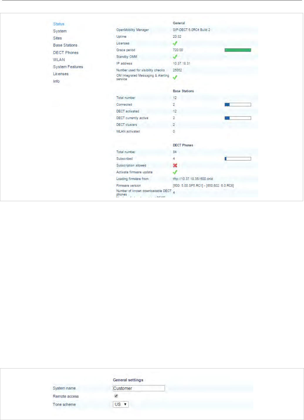
SIP-DECT OM System Manual
54
5.4 “SYSTEM” MENU
The System menu comprises general parameters to configure and administer the system parameters of
the SIP-DECT solution.
5.4.1 “SYSTEM SETTINGS” MENU
The System settings cover global settings for the OpenMobility Manager. You can perform the following
tasks from the System Settings menu:
• configure global settings (see the following sub-sections)
• restart the OMM (see section 5.4.1.15)
• update the OMM (see section 5.4.1.16)
The following sections describe the parameters that can be set.
Note: The following information describes all parameters visible when
the Advanced option (in the top bar) is enabled.
5.4.1.1 General settings
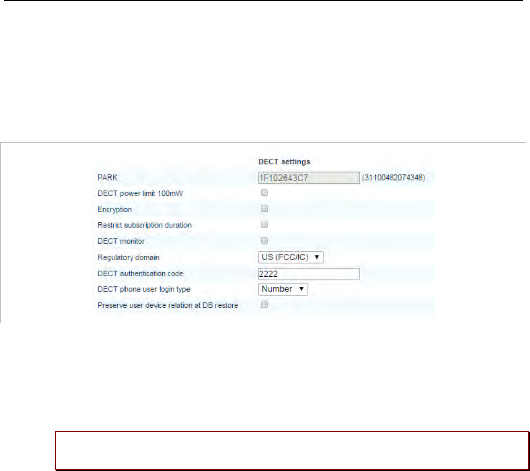
OMM Web Service
55
• System Name: Enter the system name.
• Remote Access: Switches on/off the SSH access to all DECT base stations of the DECT system. For
more information on the SSH access see section 8.3.5.
• Tone scheme: Select the country in which the OMM resides. This enables country specific tones
(busy tone, dial tone, etc).
5.4.1.2 DECT settings
• PARK: This setting depends on the licensing mode. Small systems: Enter the PARK code obtained
from the PARK service (see section 4.1.3). License file: shows the PARK included in the license file.
• DECT power limit 100mW: Limits the DECT base station transmit power to 100mW, independent of
the selected regulatory domain. Enable for SIP-DECT installations that are mobile (e.g., on cruise
liners that travel between countries). See section 3.32 for more information on this feature.
• Encryption: Activate this option if you want to enable DECT encryption for the whole system.
Please note: Make sure that all deployed third party DECT phones support DECT
encryption. If not, encryption can be disabled per DECT phone (see 6.10.4).
• Restrict subscription duration: Activate this option if you want to restrict the duration for DECT
phone subscriptions to 2 minutes after subscription activation. This option is not useful in case that
you want to subscribe more than one DECT phone at a time or together with auto-create on
subscription. It should be activated exclusively in case that there is a special need.
• DECT monitor: For monitoring the DECT system behavior of the OpenMobility Manager, the
separate DECT monitor application exists. This tool needs an access to the OpenMobility Manager
which is disabled by default and can be enabled here. Because of security, the DECT monitor flag is
not stored permanently in the internal flash memory of the OMM/DECT base station. After a reset, the
DECT monitor flag is ever disabled.
• Regulatory domain: Specifies where the IP DECT is used. Supported regulatory domains are:
- EMEA
- US (FCC/IC)
- Brazil
- Taiwan

SIP-DECT OM System Manual
56
Note that 3rd generation DECT base stations support different DECT frequencies. These devices can
operate in different regulatory domains provided that the Regulatory domain setting is configured
accordingly.
For older 2nd generation DECT base stations, there are different DECT base station models to meet
different regulatory domain demands. To setup a North American FCC compliant DECT base station,
the value must be set to US (FCC/IC). In a North American US (FCC/IC) deployment, ETSI compliant
DECT base stations are made inactive and cannot be activated if the regulatory domain is set to
US (FCC/IC). The reverse is also true.
WARNING: Please note that selecting the incorrect regulatory domain may result in a violation
of applicable laws in your country!
Note: Whenever you modify the regulatory domain, a warning is
displayed. You must confirm it first to apply the changed setting.
• DECT authentication code: The authentication code is used during initial DECT phone subscription
as a security option. A code entered here provides a system-wide DECT authentication code for each
DECT phone subscription. Alternatively, a DECT phone-specific authentication code can be set (see
section 5.7.1).
• DECT phone user login type: Specifies the system-wide variant for DECT phone login method. Two
kinds of login types are supported: the user can either be determined by the telephone number
(Number) or by the unique user login ID (Login ID). Both elements are part of each user data set.
Note: Changing this setting forces an automatic logout of all logged in
DECT phones.
• Preserve user device relation at DB restore: Enables the preservation of the user – DECT phone
association with an OMM database restore.
Note: If you want to restore the association, enable this option
BEFORE uploading a database for an OMM restore. The current
OMM value is used, not the setting in the database being
uploaded.
5.4.1.3 WLAN settings
This setting applies to RFP 42 WLAN and RFP 43 WLAN base stations.
In the Regulatory domain field, select the regulatory domain of the WLAN network. This setting
depends on the country and is prescribed by the laws of that country. Only the setting prescribed for that
country must be used. For more information on the WLAN settings see the sections 5.8 and 7.18.
WARNING: Please note that selecting the incorrect regulatory domain may result in a violation
of applicable law in your country!
Note: Whenever you modify the regulatory domain, a warning is
displayed. You must confirm it first to apply the changed setting.
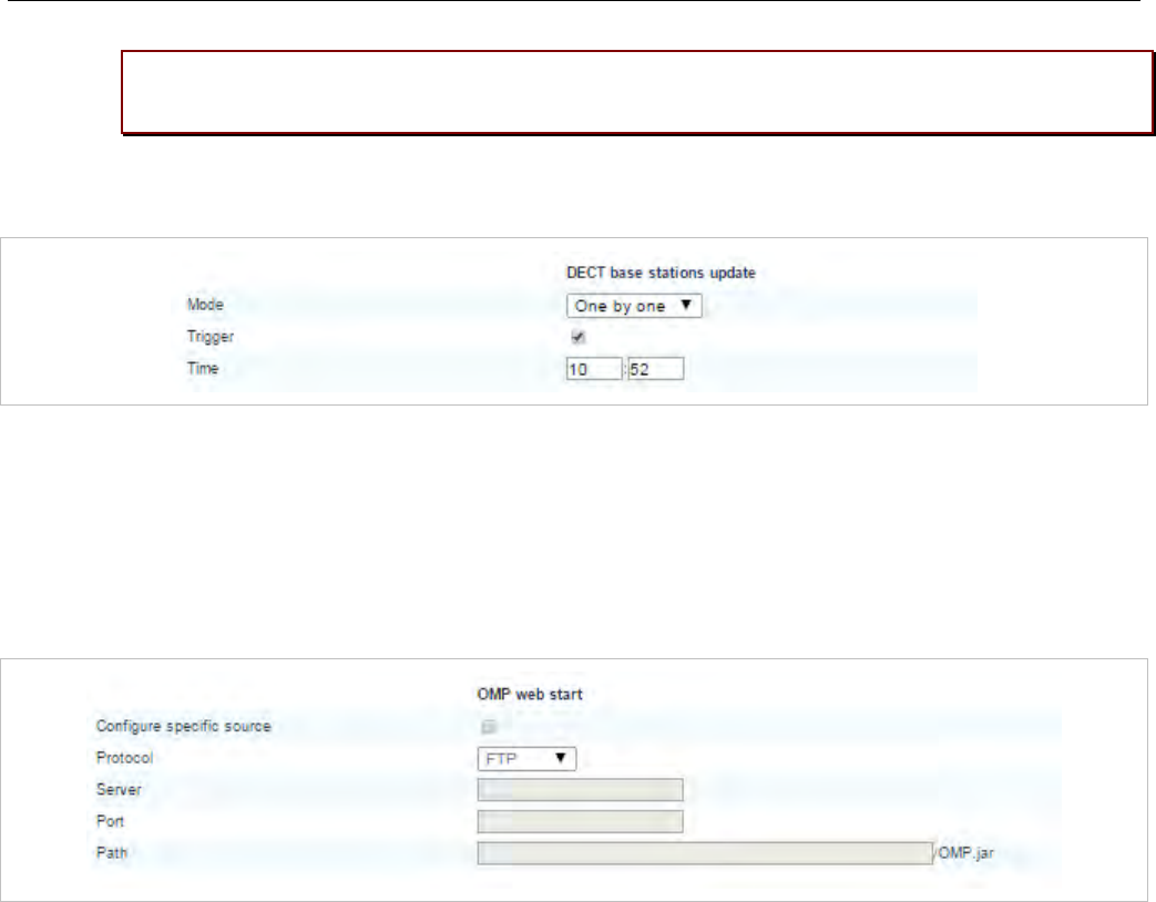
OMM Web Service
57
Please note: If you upgrade a system to release 3.0 or higher, you must configure the
appropriate regulatory domain.
5.4.1.4 DECT base stations update
• Mode: DECT base station update mode – “One by one” (every single DECT base stations is updated
separately) or “All at once” (all DECT base stations are updated in one step)
• Trigger: When this option is selected, the DECT base station update is time-controlled.
• Time: Time for time controlled updates
5.4.1.5 OMP web start
• Configure specific source: Enables the specific URL to an external file server for retrieving the OMP
jar file.
• Protocol: Specifies the protocol used to retrieve the OMP file.
• Server: Specifies the IP address or name of the external file server.
• Port: Specifies the port of the external file server.
• Path: Specifies the location of the OMP jar file on the external file server.
5.4.1.6 DECT phone’s firmware update
With SIP-DECT 6.0 or later, the DECT base station software image (iprfp3G.dnld) contains the Mitel 600
DECT phone software. For specific maintenance purposes only, you can configure a URL to use an
alternative DECT phone software image. The Mitel 600 DECT phone firmware packages are delivered in
the “600.dnld” file for the OMM running on a DECT base station.
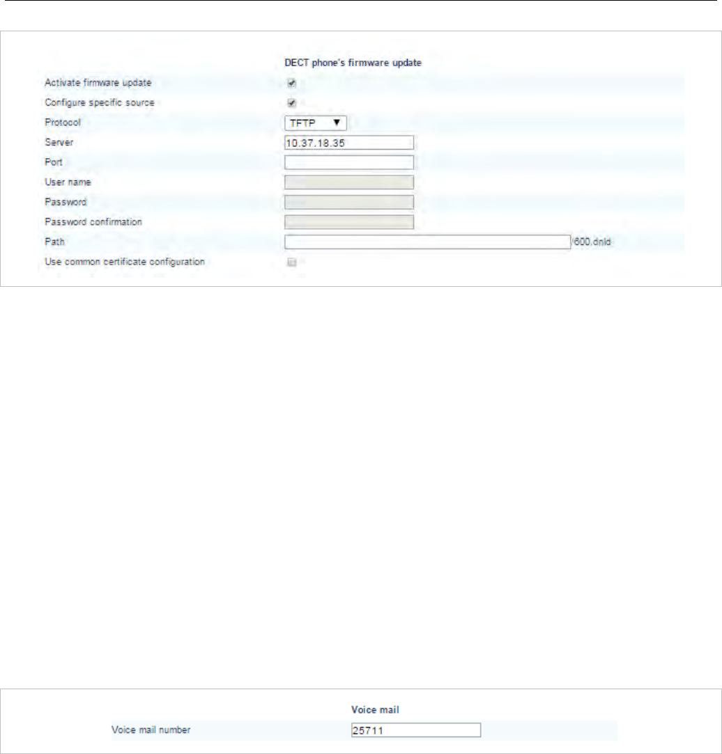
SIP-DECT OM System Manual
58
• Activate firmware update: Enables or disables the “Download over Air” feature. The OMM provides
a DECT phone firmware update over the air when this feature is activated. For more information on,
see section 7.22.
• Configure specific source: Enables the specific URL to an external file server for retrieving the
DECT phone firmware file.
• Protocol: Specifies the protocol used to retrieve the firmware file from the external server.
• Server: Specifies the IP address or name of the external file server.
• Port: Specifies the port of the external file server.
• User name: Specifies the user name to authenticate on the external file server.
• Password: Specifies the password to authenticate on the external file server.
• Password confirmation: Confirms the password to authenticate on the external file server.
• Path: Specifies the location of the firmware file on the external file server.
• Use common certificate configuration: Enables the use of the system-wide certificate validation
settings for this URL, as configured on the System -> Provisioning -> Certificates page (see section
5.4.2).
5.4.1.7 Voice mail
• Voice mail number: Specifies a system-wide voice mail number. This number is used by the
Mitel 600 DECT phone family if the voice box is called.
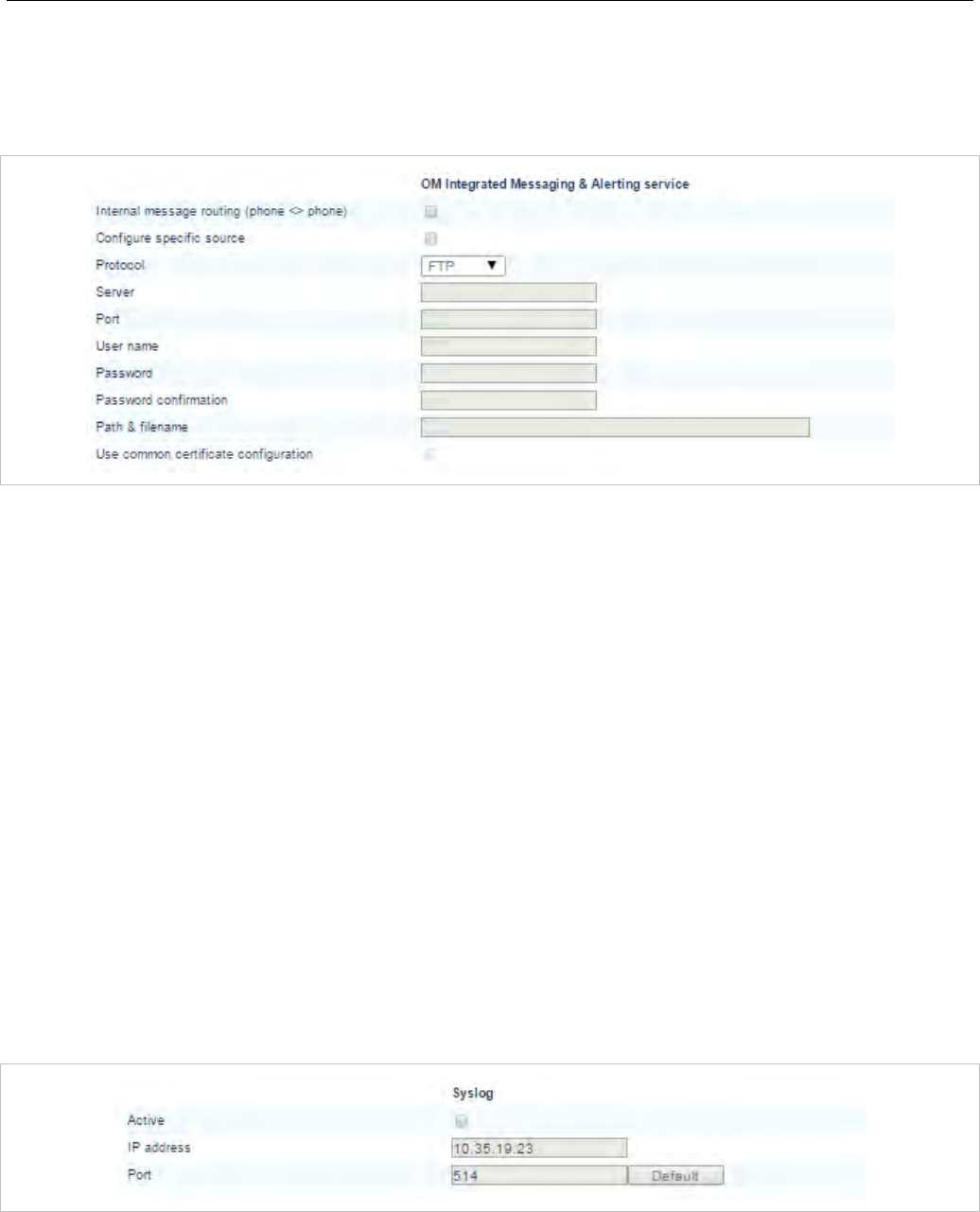
OMM Web Service
59
5.4.1.8 OM Integrated Messaging & Alerting service
The OpenMobility Manager provides an integrated message and alarm service. The Internal message
routing (DECT phone <> DECT phone) can be activated/deactivated. For a detailed description, see
/28/.
• Internal message routing (phone <> phone): Enables or disables internal messaging between
DECT phones.
• Configure specific destination: Enables the specific URL to an external file server for retrieving the
IMA configuration file.
• Protocol: Specifies the protocol used to retrieve the IMA configuration file from the external server.
• Server: Specifies the IP address or name of the external file server.
• Port: Specifies the port of the external file server.
• User name: Specifies the user name to authenticate on the external file server.
• Password: Specifies the password to authenticate on the external file server.
• Password confirmation: Confirms the password to authenticate on the external file server.
• Path & filename: Specifies the location and file name of the IMA configuration file on the external file
server.
• Use common certificate configuration: Enables the use of the system-wide certificate validation
settings for this URL, as configured on the System -> Provisioning -> Certificates page (see section
5.4.2).
5.4.1.9 Syslog
The OMM and the DECT base stations are capable of propagating syslog messages.
• Active: Enables or disables collection of syslog messages.
• IP address: Address of the host that should collect the syslog messages.
• Port: Port of the host that should collect the syslog messages.
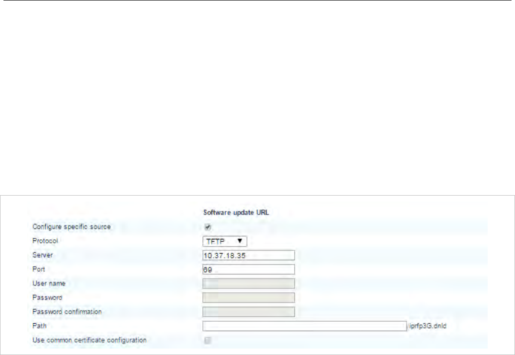
SIP-DECT OM System Manual
60
• Forward OMM Messages to syslog: (Visible only on a PC-hosted OMM system) Enables/disables
forwarding of syslog messages from the PC-hosted OMM.
5.4.1.10 Software update URL
With SIP-DECT 6.0 or later, DECT base stations in small SIP-DECT systems (~10 RFPs) can obtain
their software image from the DECT base station hosting the OMM, if they have no valid URL from which
to load their software (see section 7.9.2 for information on URL syntax). If the OMM is running on a
DECT base station, the OMM DECT base station delivers the software to the connected DECT base
stations.
The new software image for the OMM DECT base station can be provided as an iprfp3G.dnld file on an
external file server. You configure the URL for the software image in this section.
• Configure specific source: Enables the specific URL for downloading the iprfp3G.dnld file (as
opposed to the ConfigURL, which points to an external file server for all configuration and resource
files).
• Protocol: Specifies the protocol used to fetch the software image file.
• Port: Specifies the port of the external file server.
• Server: Specifies the IP address or name of the external file server.
• User name: Specifies the user name to authenticate on the external file server.
• Password: Specifies the password to authenticate on the external file server.
• Password confirmation: Confirms the password to authenticate on the external file server.
• Path: Specifies the location of the software image file on the external file server.
• Use common certificate configuration: Enables the use of the system-wide certificate validation
settings for this URL, as configured on the System -> Provisioning -> Certificates page (see section
5.4.2).
5.4.1.11 System dump
A system dump is a file that holds information about the OpenMobility Manager and all connected DECT
base stations. With the Remote System Dump feature, a system dump is transferred to a remote server.
You can configure a specific destination, otherwise the system ConfigURL is used. The system dump is
generated manually by pressing the Dump button or automatically at the specified time.
Please ensure that the fileserver used allows writing or creation of system dumps.
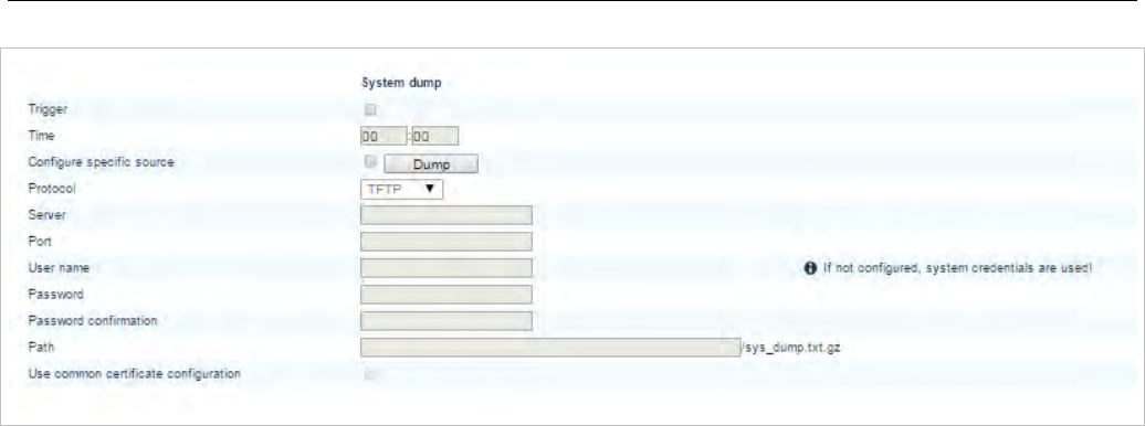
OMM Web Service
61
• Trigger: Enables the automatic generation of a system dump time every day at the time specified in
the Time field.
• Time: The time of day the system automatically generates a system dump file (only activated if the
Trigger checkbox is enabled).
• Dump: Immediately triggers the generation of a system dump file.
• Configure specific source: Enables the specific URL for transferring the system dump file (as
opposed to the ConfigURL, which points to an external file server for all configuration and resource
files).
• Protocol: Specifies the protocol used to transfer the system dump file.
• Port: Specifies the port of the external file server.
• Server: Specifies the IP address or name of the external file server.
• User name: Specifies the user name to authenticate on the external file server.
• Password: Specifies the password to authenticate on the external file server.
• Password confirmation: Confirms the password to authenticate on the external file server.
• Path: Specifies where the system dump file is stored on the external file server.
• Use common certificate configuration: Enables the use of the system-wide certificate validation
settings for this URL, as configured on the System -> Provisioning -> Certificates page (see section
5.4.2).
5.4.1.12 Core dump URL
Fatal software problems may result in memory dumps, in core files. The DECT base station can transfer
the core files to a remote fileserver. With SIP-DECT 6.0 or later, you can configure a specific URL to an
external file server where core dump files should be transferred and stored. The Core dump URL is used
by each DECT base station connected to the OMM.
Without a configured Core dump URL, whether and where core files are transferred is dependent on
specific DECT base station settings. Without any special configuration, the files are transferred to the
server that is used to retrieve the system software (i.e., the directory of the boot image).
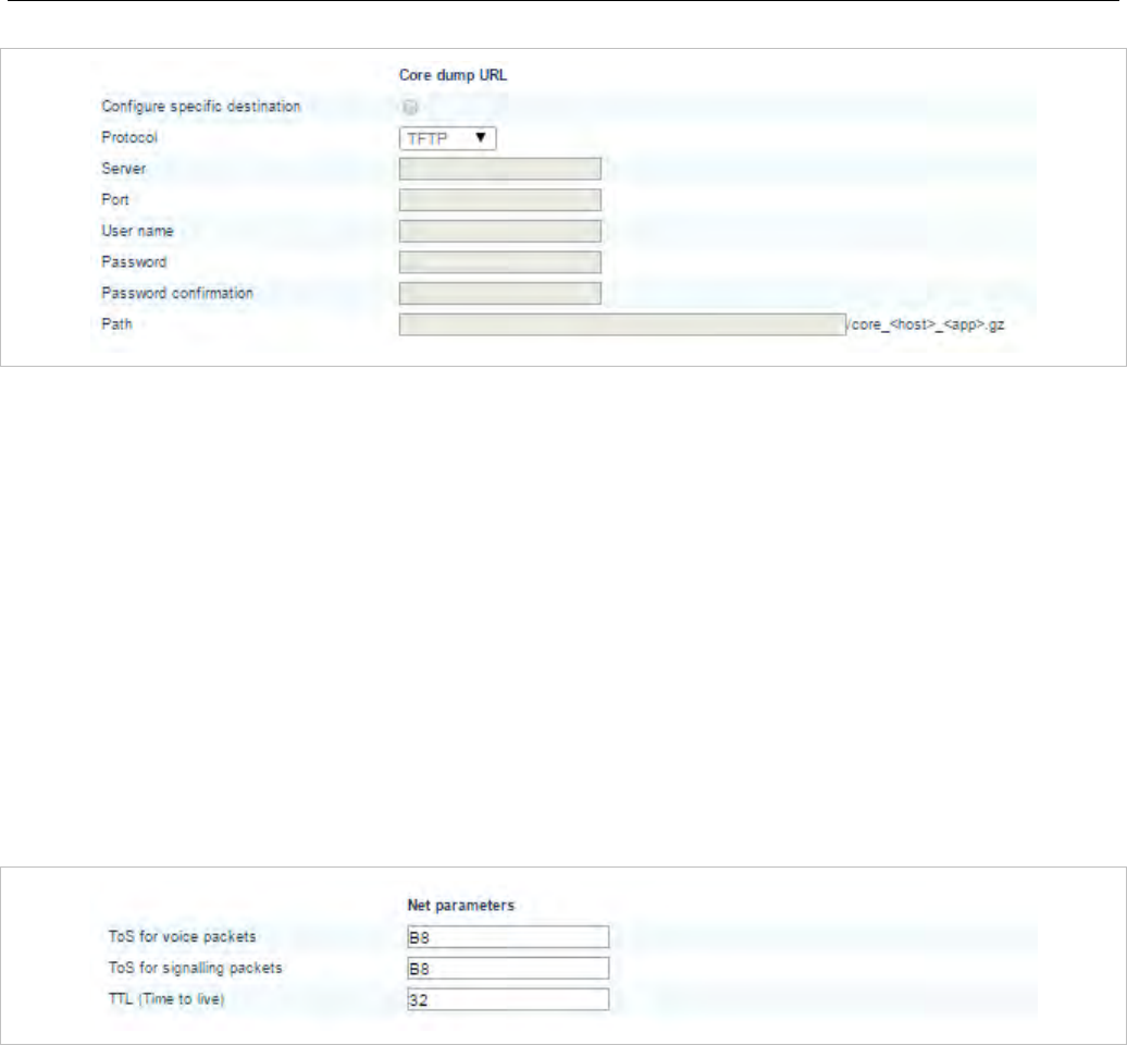
SIP-DECT OM System Manual
62
• Configure specific destination: Enables the specific URL to an external file server for transferring
and storing core files.
• Protocol: Specifies the protocol used to transfer the core files.
• Server: Specifies the IP address or name of the external file server.
• Port: Specifies the port of the external file server.
• User name: Specifies the user name to authenticate on the external file server.
• Password: Specifies the password to authenticate on the external file server.
• Password confirmation: Confirms the password to authenticate on the external file server.
• Path: Specifies the location of the core files on the external file server.
5.4.1.13 Net parameters
To allow the prioritization of Voice Packets and/or Signaling Packets (SIP) inside the used network the IP
parameter ToS (Type of Service) should be configured.
• ToS for voice packets: Determines the type of service (ToS resp. DiffServ) byte of the IP packet
header for all packets that transport RTP voice streams.
• ToS for signalling packets: Determines the type of service (ToS resp. DiffServ) byte of the IP packet
header for all packets related to VoIP signaling.
• TTL (Time to live): Determines the maximum hop count for all IP packets.
5.4.1.14 Date and time
If OMM DECT base stations start an SNTP client, the date and time of the configured time zone is
synchronized with the Mitel DECT 142 / Mitel 142d and Mitel 600 DECT phones. The date and time will
be provided by the OMM to these DECT phones if they initiate a DECT location registration. The rules
for a time zone can be configured in the Time zones menu (see section 5.4.5).
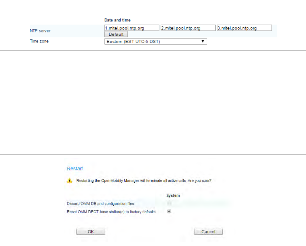
OMM Web Service
63
• NTP server: The NTP servers used for time synchronization.
• Time zone: Specifies the time zone in which the OMM is operating. This feature is exclusively
available on the OMM DECT base station. On PC-OMM configurations, the PC time and time zone is
used.
5.4.1.15 Restarting the OMM
You can restart the OMM by clicking on the Restart button in the top right corner of the System
Settings page.
1 Click on the Restart button.
The Restart dialog window opens.
2 In the Restart dialog window, set the following options:
• Discard OMM DB and configuration files: Specifies whether OMM database and configuration data
is removed from the DECT base station, including the data retrieved from RCS. Local IP configuration
remains unaffected. This parameter is only available on an OMM DECT base station.
• Reset OMM RFP(s) to factory defaults: Specifies whether all data is removed from the DECT BASE
STATION including the OMM database, configuration files and local IP configuration.
Note: Both options also affect the standby OMM.
3 Click OK.
A Restart web page opens and displays a progress bar. The login page is loaded automatically if the
OMM is reachable again.
5.4.1.16 Updating the OMM
An Update button is available on the System settings web page. Pressing the Update button forces the
DECT base stations to check for new software and initiates the software update. For more details about
updating the OMM see the section 7.14.
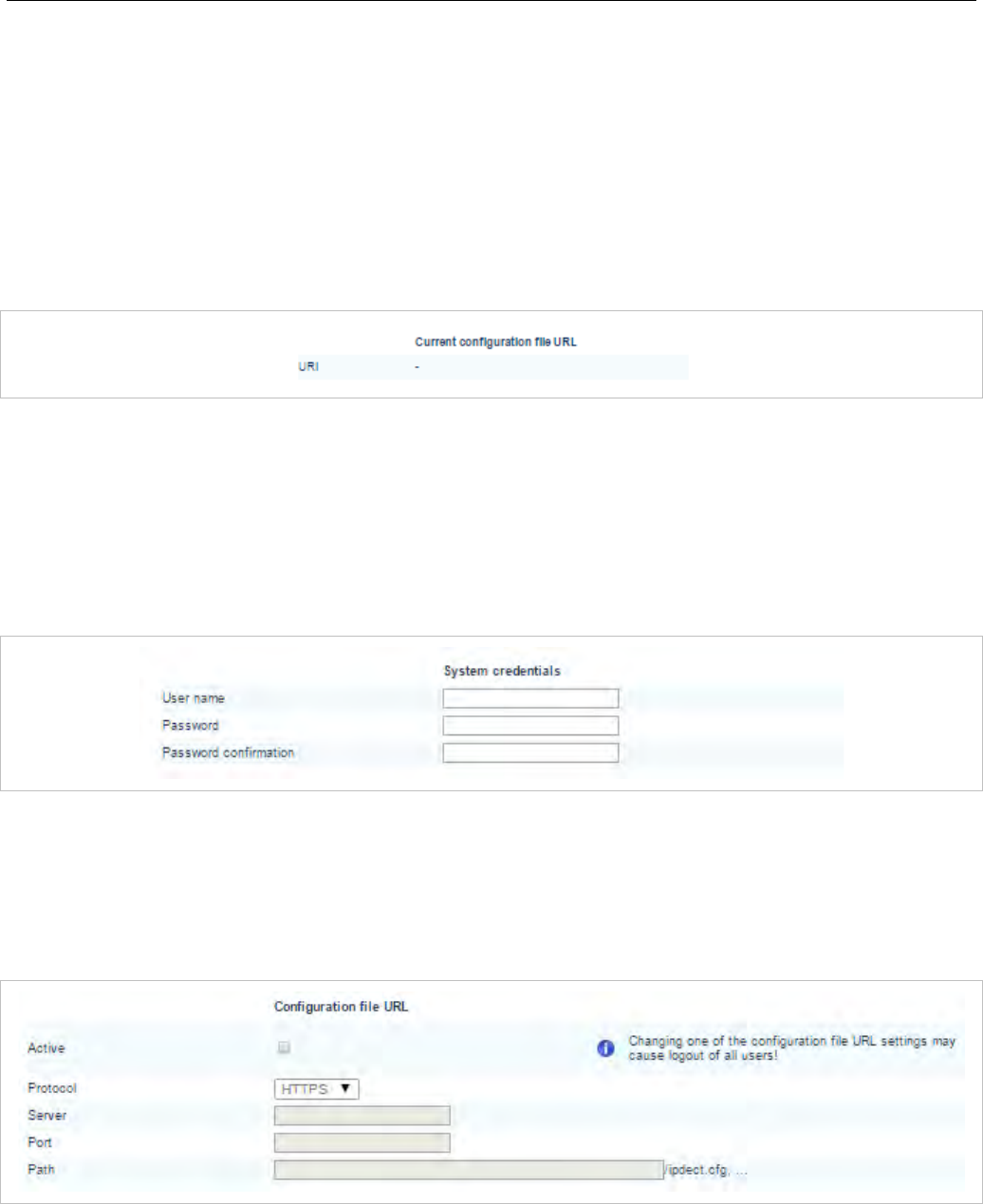
SIP-DECT OM System Manual
64
5.4.2 ”PROVISIONING” MENU
SIP-DECT supports provisioning through external configuration files. With SIP-DECT 6.0 or later, you
can configure a URL for an external file server, from which all configuration files can be downloaded. The
configured provisioning server URL is used for secure connections to the file server to retrieve
configuration or firmware files. For more information on this feature, see section 7.8.1.
The Provisioning menu allows you to set parameters for the external provisioning server.
5.4.2.1 Current configuration file URL
• Current configuration file URL: URL for the configuration file that is currently loaded.
5.4.2.2 System credentials
System credentials are used to retrieve configuration and resource files from the configured provisioning
server for protocols supporting authentication or servers requesting authentication. For HTTP/HTTPS,
basic and digest authentication are supported. System credentials can also be inherited for specific
URLs, where no user credentials are specified.
• User name: Specifies the user name for authentication against the provisioning server.
• Password: Specifies the password for authentication against the provisioning server
• Password confirmation: Confirms the password for authentication against the provisioning server.
5.4.2.3 Configuration file URL
• Active: Enables or disables the configuration file URL feature.
• Protocol: Specifies the protocol to be used to fetch the configuration files.
• Server: Specifies the IP address or name of the provisioning server.
• Port: Specifies the provisioning server’s port number.
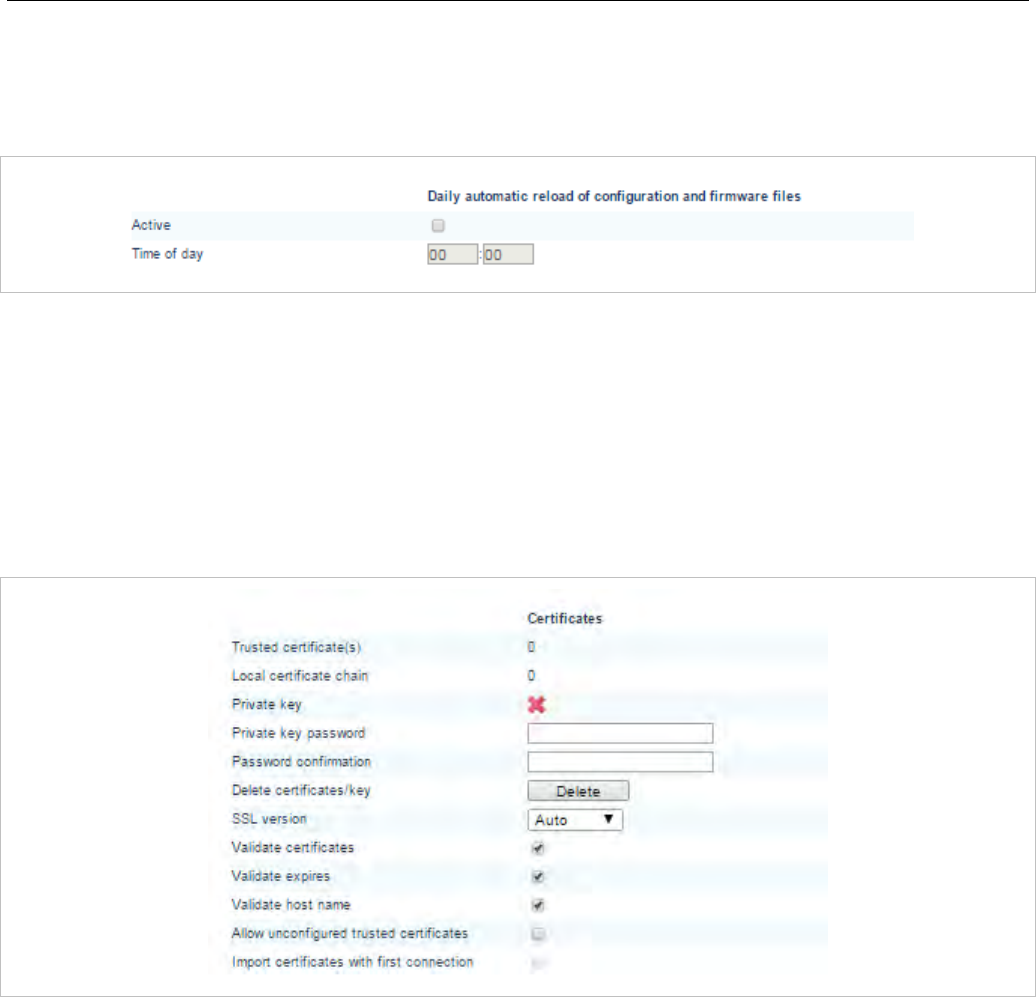
OMM Web Service
65
• Path: Specifies the path to the configuration and resource files on the provisioning server.
5.4.2.4 Daily automatic reload of configuration and firmware files
• Active: Enables automatic reload of the configuration and resource files on a daily basis, at the
specified time.
• Time of day: Time for scheduled reload of configuration and firmware files.
5.4.2.5 Certificates
The OMM uses a trusted certificate chain to validate the server. This is required if the server has no
certificate derived from a trusted CA root certificate, where the OMM uses the Mozilla CA Certificate List.
You can specify the validation methods to be used.
• Trusted certificate(s): Read-only; specifies the number of trusted certificates deployed on the OMM.
• Local certificate chain: Read-only; specifies the number of local certificate chains deployed on the
OMM.
• Private key: Read-only; specifies whether a private key file is deployed on the OMM.
• Private key password: Specifies a password for the private key file.
• Password confirmation: Confirms the password for the private key file.
• Delete certificates/key: Allows the user to delete existing certificates and private key files from the
OMM.
• SSL version: The SSL protocol version to use for the configuration file server connection. Available
options are: TLS1.0, TLS1.1, TLS1.2 or AUTO, where AUTO accepts all protocol versions.
• Validate certificates: Enables or disables certificate validation. If enabled, the server certificate is
validated against trusted CA’s (signed by a CA from the Mozilla CA certificate list) and the configured
trusted certificates.
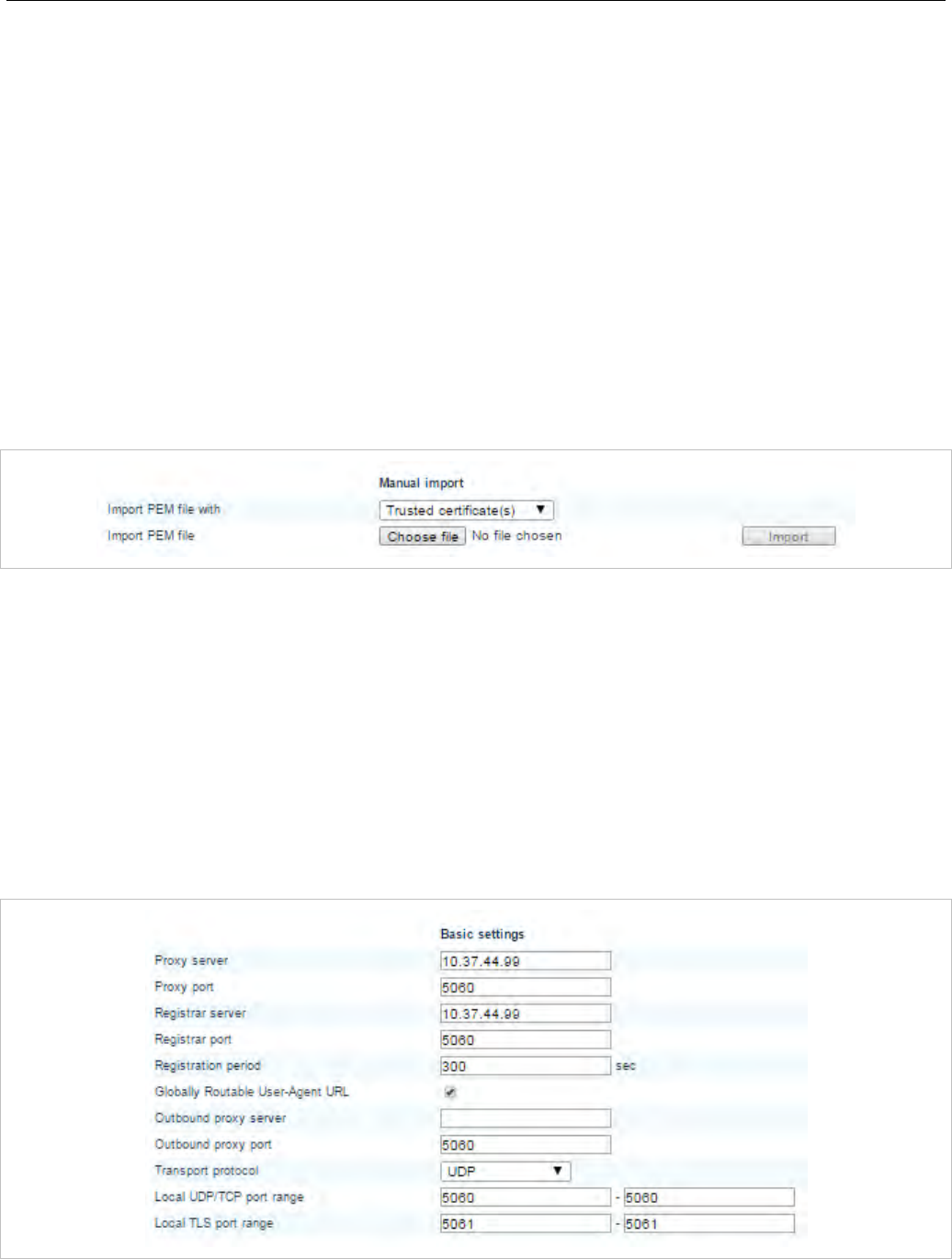
SIP-DECT OM System Manual
66
• Validate expires: Enables or disables the validation of certificate expiry. When this parameter is
enabled, the client verifies whether or not a certificate has expired prior to accepting the certificate.
• Validate host name: Enables or disables the validation of hostnames on the OMM.
• Allow unconfigured trusted certificates: If enabled, this parameter disables any server certificate
validation as long as no trusted certificate was imported into the OMM. AXI commands in a received
configuration file may import such trusted certificates into the OMM.
• Import certificates with first connection: If enabled (in conjunction with the Allow unconfigured
trusted certificates parameter), the trusted certificate will be imported from the cert chain delivered in
the server response without any validation, as long as no trusted certificate was imported previously
into the OMM.
5.4.2.6 Manual import
You can overwrite the hard coded OMM certificate by importing trusted certificates, a local certificate
chain and a private key file.
• Import PEM file with: Specifies the type of file to be imported (trusted certificate, local certificate, or
private key).
• Import PEM file: Specifies the location of the file to be imported.
5.4.3 ”SIP” MENU
The SIP settings cover all global settings matching the SIP signaling and the RTP voice streams.
Parameters are grouped under the tabs described below.
5.4.3.1 Basic settings
You can set basic SIP settings for the system on the Basic settings menu.

OMM Web Service
67
• Proxy server: IP address or name of the SIP proxy server. If a host name and domain are used for
the proxy server parameter, ensure that a DNS server and a domain are specified for your SIP-DECT
system via DHCP or the OM Configurator tool.
• Proxy port: SIP proxy server’s port number. Default is “5060”. To enable DNS SRV support for proxy
lookups, use a value of “0” for the proxy port. In case that TLS is used, the value shall be changed to
“5061”.
• Registrar server: IP address or name of the SIP registrar. Enables the DECT phones to be
registered with a registrar. If a host name and domain are used for the proxy server parameter,
ensure that a DNS server and a domain are specified for your SIP-DECT system via DHCP or the OM
Configurator tool.
• Registrar port: SIP registrar’s port number. Default is “5060”. To enable DNS SRV support for
registrar lookups, use a value of “0” for the registrar port. In case that TLS is used, the value shall be
changed to “5061”.
• Registration period: The requested registration period, in seconds, from the registrar. Default is
“3600”.
• Globally Routable User Agent (URL): Enables support for Globally Routable User-Agent URIs
(GRUUs). GRUUs provide a way for anyone on the Internet to route a call to a specific instance of a
SIP User-Agent.
• Outbound proxy server: This setting is optional. You can enter the address of the outbound proxy
server in this field. All SIP messages originating from the OMM are sent to this server. For example, if
you have a Session Border Controller in your network, then you would normally set its address here.
• Outbound proxy port: The proxy port on the proxy server to which the OMM sends all SIP
messages. Default is “5060”. In case that TLS is used, the value shall be changed to “5061”.
• Transport protocol: The protocol used by the OMM to send/receive SIP signaling. Default is “UDP”.
• Local UDP/TCP port range: The port range to be used for DECT users when UDP/TCP is used as
the transport protocol. The default is 5060 – 5060.
• Local TLS port range: The port range to be used for DECT users when TLS is used as the transport
protocol. The default is 5061 – 5061.
There are certain rules to note when configuring port ranges; see section 3.7 for more information.
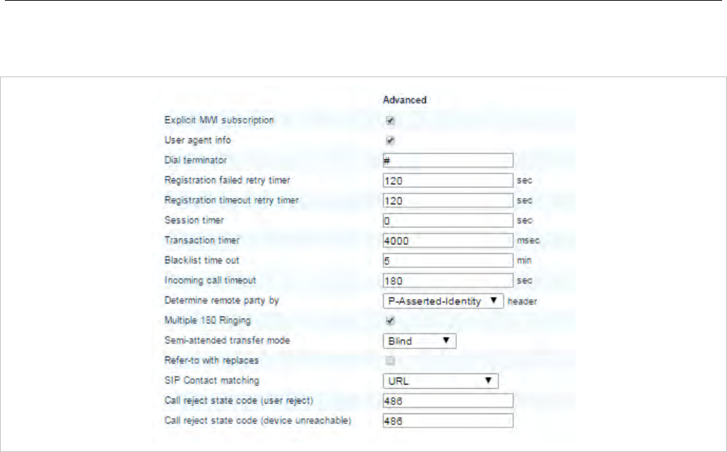
SIP-DECT OM System Manual
68
5.4.3.2 Advanced settings
You can set more advanced SIP settings for the system on the Advanced settings menu.
• Explicit MWI subscription: Some SIP Call Managers such as the Asterisk support Message Waiting
Indication (MWI) based on /21/. An MWI icon is displayed on a DECT phone (Mitel DECT 142 / Mitel
142d, Mitel 600) if the user has received a voice message on his voice box which is supported by the
SIP Call Manager. If Explicit MWI subscription is enabled, the OMM sends explicit for each DECT
phone an MWI subscription message to the Proxy or Outbound Proxy Server.
• User agent info: If this option is enabled, the OMM sends information on his version inside the SIP
headers User-Agent/Server.
• Dial terminator: The dial terminator is configurable (up to 2 characters; “0” – “9”, “*”, “#” or empty).
The default dial terminator is “#”. A dial terminator is necessary if digit treatment shall be applied on
outgoing calls and overlapped sending is used.
• Registration failed retry timer: Specifies the time, in seconds, that the OMM waits between
registration attempts when the registration is rejected by the registrar. Default is “1200” seconds.
• Registration timeout retry timer: Specifies the time that the OMM waits between registration
attempts when the registration timed out. Default is “180” seconds.
• Session timer: The interval, in seconds, between re-INVITE requests sent from the OMM to keep a
SIP session alive. The minimum session timer is 90 seconds and the maximum is 86400 seconds.
The default is 0 (i.e., feature is disabled).
• Transaction timer: The time period in milliseconds that the OMM allows a call server (proxy/registrar)
to respond to SIP messages that it sends. If the OMM does not receive a response in the time period
designated for this parameter, the OMM assumes the message as timed out. In this case the call
server is recorded to the blacklist. Valid values are “4000” to “64000”. Default is “4000” milliseconds.
• Blacklist time out: The time period in minutes an unreachable call server stays in the blacklist. Valid
values are “0” to “1440”. Default is “5” minutes.
• Incoming call timeout: The time, in seconds, that the OMM waits for a user to accept an incoming
call before rejecting the call automatically. The minimum time is 30 seconds and the maximum is 300
seconds. The default is 180 seconds.

OMM Web Service
69
• Determine remote party by: You can select the SIP header from which the remote party information
(user id and display name) should be determined. If P-Asserted-Identity (default value) is selected
but no such header is received, a fallback to the mandatory From / To header will be done. This
feature can be configured by choosing one of the two values.
Note: When SIP-DECT receives a SIP header P-Asserted-Identity in
ringing state during an outgoing call, the included identity
information (e.g. SIP display name and user-id) will be displayed
on Mitel 600 and Mitel 142d phones as new call target. In
addition, the outgoing call log of the Mitel 600 and Mitel 142d
phones will be updated with the new given identity.
• Multiple 180 Ringing: If this feature is deactivated, the OMM sends out only one 180 Ringing
response for an incoming call if PRACK is not supported. If this feature is activated, the OMM
retransmits multiple times the 180 Ringing response for an incoming call if PRACK is not supported.
This ensures that the calling side receives a 180 Ringing response in case of packet losses on the
network. By default this feature is active.
• Semi-attended transfer mode and Refer-to with replaces:
Semi-attended
transfer mode
Refer-to with
replaces
Behavior
Blind No The semi-attended transfer is handled as a blind transfer. The phone
sends CANCEL before REFER for semi-attended transfer.
Blind Yes The semi-attended transfer is handled as a blind transfer. The phone
sends REFER with Replaces for semi-attended transfer and no
CANCEL. This behavior is not SIP compliant but necessary for some
iPBX platforms.
Attended - The semi-attended transfer is handled as an attended transfer. Both
lines of the transferor remain active until the transfer succeeds. This
behavior is compliant to RFC 5589.
Please note: The mode “Semi-attended transfer mode: Blind” with “Refer-to with replaces:
yes” is not SIP compliant and should only be used on iPBX platforms that require this type
of signaling.
• SIP contact matching: Specifies the method used by the OMM to match the Contact header in a SIP
response to a REGISTER request. Available options are:
- URI – match user username, domain name, phone IP and port and transport
- IP only – match the IP address of the phone only
- Username only – match the username only
- IP and user name – match the IP address of the phone and the username
The default is URI.
• Call reject state code (user reject): Specifies the SIP state code sent as response when the user
rejects an incoming call by pressing the “Reject” option. Valid values are “400” to “699”. The default is
“486”
• Out of range state code (device unreachable): Specifies the SIP state code sent as response when
the incoming call is rejected because the DECT phone is unreachable (e.g., the DECT phone is out of
range or out of battery power). Valid values are “400” to “699”. The default is 486.
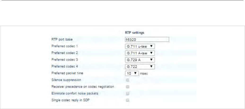
SIP-DECT OM System Manual
70
5.4.3.3 RTP settings
You can set RTP parameters in the RTP settings section.
• RTP port base: Each RFP needs a continuous port area of 68 UDP ports for RTP voice streaming.
The RTP port base is the start port number of that area. Default is “16320”.
• Preferred codec 1 – 4: Specifies a customized codec preference list which allows you to use the
preferred codecs. The Codec 1 has the highest and Codec 4 the lowest priority.
Note: With SIP-DECT Release 3.0 or higher the voice codecs G.722
(wideband), G.711 u-law, G.711 A-law and G.729 A are
supported. The previously supported codec G.723 is no longer
available.
• Preferred packet time (10, 20 or 30 msec): Determines the length of voice samples collected before
sending out a new RTP packet. A small setting improves voice quality at the expense of data
transmission overhead. Default is “20” milliseconds.
• Silence suppression: Enables automatic silence detection in the RTP voice data stream to optimize
the data transfer volume.
• Receiver precedence on CODEC negotiation:
- The ON (option is enabled) setting means:
The CODEC selection for incoming SDP offers based on the own preference order list. The first
entry in the OMM preferred codec list matching an entry in the incoming SDP offer will be selected.
- The OFF (option is disabled) setting means:
The CODEC selection based on the preference order list of incoming SDP offer. The first entry in
the incoming order list matching an entry of OMM preferred codec list will be selected. This is the
default and is as recommended in RFC 3264.
• Eliminate comfort noise packets: If this feature is activated, then comfort noise packets are
removed from the RTP media stream which causes gaps in the sequence numbers. This can be used
if comfort noise packets e.g. in G.711 media streams disturb voice calls in certain installations.
• Single codec reply in SDP: If this feature is activated, the OMM answers to SDP offers (included in
the SIP signalization) with a single codec in the SDP answer.
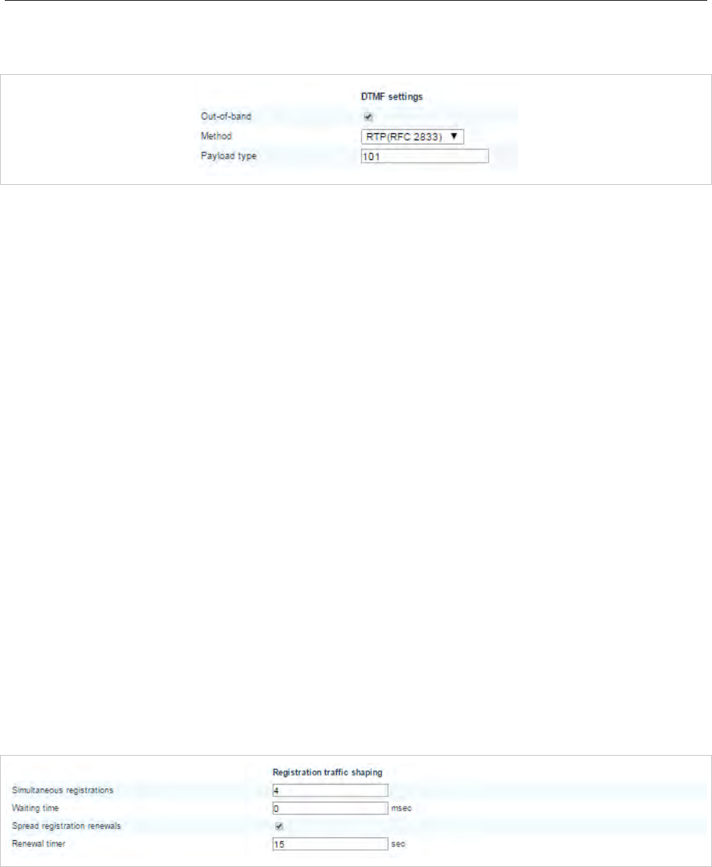
OMM Web Service
71
5.4.3.4 DTMF settings
You can set DTMF parameters in the DTMF section.
• Out-of-band: Used to configure whether DTMF Out-of-band is preferred or not.
• Method: The OMM supports the following DTMF Out-of-band methods:
- RTP (RFC 2833)
Transmits DTMF as RTP events according to RFC 2833 (/14/) after the payload type negotiation
via SIP/SDP. If the payload type is not negotiated, “in band” will be used automatically.
- INFO
The SIP INFO method is used to transmit DTMF tones as telephone events (application/dtmf-relay).
This setting should be used if RFC 2833 is not supported.
- BOTH
DTMF telephones events are send according to RFC 2833 and as well as SIP INFO method. Note:
Possibly, the other party recognizes events twice.
• Payload type: If the Out-of-band option is enabled, this setting specifies the payload type which is
used for sending DTMF events based on section 3.1, reference /14/.
5.4.3.5 Registration traffic shaping
Registration traffic shaping parameters allow you to limit the number of simultaneous SIP registrations at
startup/fail over of the OMM. This feature is always activated because disabling it may overload the
OMM or the call server.
Some providers use a keep-alive mechanism based on SIP registration renewals for remote endpoints
that are behind a Network Address Translator (NAT), as in an IP-Centrex solution. The keep-alive
mechanism keeps the pinhole open and ensures communication between the remote endpoint and the
Session Border Controller (SBC).
The OMM feature that spreads the registration renewals to prevent bottlenecks in large systems is not
compatible with the keep-alive mechanism. With SIP-DECT 6.0 or later, you can disable the spread
mechanism and configure a registration renewal timer to allow support for the NAT feature.
• Simultaneous registrations: The maximum number of simultaneously started registrations.
• Waiting time: The waiting time between a registration finish and starting the next registration in ms
(0-1000ms).
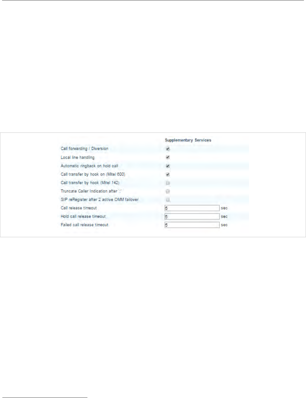
SIP-DECT OM System Manual
72
• Spread registration renewals: If set to ON, the OMM distributes all DECT phone registration
renewals automatically, between half-way through the registration period and 30 seconds before
expiry. This prevents registration renewal bottlenecks. Default is ON.
• Renewal timer: The time, in seconds, during which the OMM renews DECT phone registrations
before expiry (if “Spread registration renewals” is set OFF). The DECT phone automatically sends
registration renewals half-way through the registration period, unless the half-way point is greater than
the threshold value. For example, if the threshold value is set to 60 seconds and the registration
period is 600 seconds, the phone sends the renewal REGISTER message 60 seconds prior to the
expiration of the registration period. If the registration period is 100 seconds, the renewal is sent at the
half-way point as (100/2) < 60. Valid values are 0 to 2147483647. Default is 15.
5.4.3.6 Supplementary Services
The Supplementary Services section contains various parameters releated to call control.
• Call forwarding / Diversion: The DECT phone user can (de)activate call forwarding/diversion in the
OMM via DECT phone menu. In some installations the implemented call forwarding/diversion feature
in the IPBX system is in conflict with the OMM-based call forwarding/diversion. Thus, the OMM-based
call forwarding/diversion can be deactivated to let the menu on the DECT phone disappear. This
setting becomes active on DECT phones with the next DECT “Locating Registration” process (can be
forced by switching the DECT phone off and on again). Call forwarding that is already activated is
ignored if the call forwarding feature is deactivated.
• Local line handling: In some installations the implemented multiple line support in the IPBX system
is in conflict with the OMM based multiple line support. Thus, the OMM based multiple line support
can be deactivated. Note, that the OMM based multiple line support is active by default.
A deactivation of the “Local line handling” flag results in the following implications:
- Only one line is handled for each user (except for an SOS call 1)
- If a user presses the “R” key or hook-off key in a call active state, a DTMF event is send to the
IPBX via SIP INFO including signal 16 (hook-flash). All Hook-flash events are sent in every case via
SIP INFO, independent of the configured or negotiated DTMF method during call setup. All other
key events are sent via the configured or negotiated DTMF method.
1 The OM SOS call feature is unchanged. The initiation of a SOS call in call active state results in the
creation of a new line which handles the SOS call.
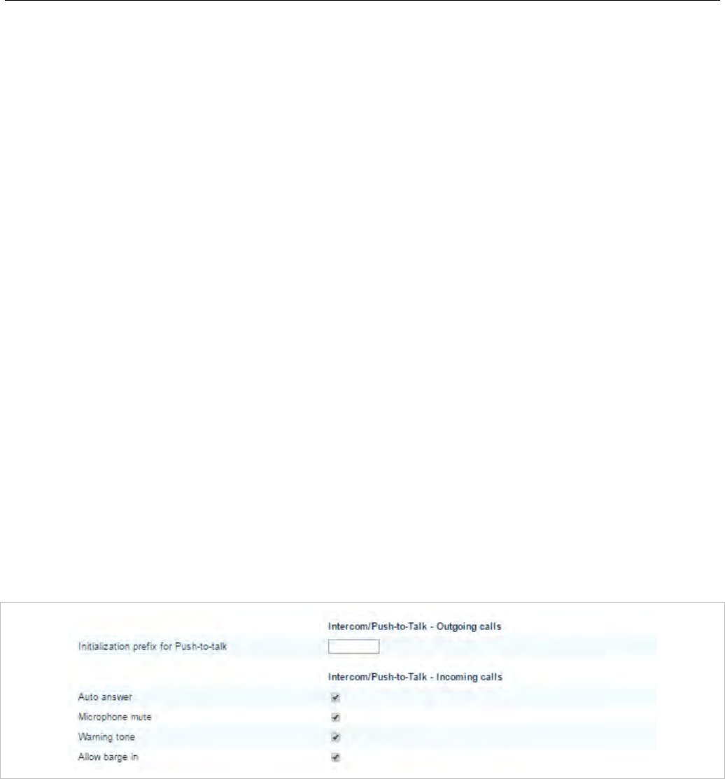
OMM Web Service
73
- The OMM-based call features “Call waiting”, “Call Transfer”, “Brokering” and “Hold” are no longer
supported.
- This setting becomes active on DECT phones with the next DECT “Locating Registration” process
(can be forced by switching the DECT phone off and on again).
• Automatic ringback on hold call: Enables or disables a ringback on the loudspeaker if the B party
of the active line releases the call. The ringing begins after the call release timeout interval (see
description below).
• Call transfer by hook on (Mitel 600): Enables call transfer via the hook key on a Mitel 600 DECT
phone (in addition to call transfer via menu).
• Call transfer by hook on (Mitel 142): Enables call transfer via the hook key on a Mitel 142 DECT
phone (in addition to call transfer via menu).
• Truncate Caller Indication after ‘;’: If the user name info in SIP to-/from-/contact headers or p-
asserted-identity is extended by a suffix, which is separated by a semicolon, this suffix is truncated
before the username is printed to call displays or DECT phone internal call logs.
• SIP reRegister after 2 active OMM failover: Enables SIP re-registration of all users from the active
OMM when the system detects two active OMMs (in a failover scenario).
• Call release timeout: Specifies the time, in seconds, after which an active line is released if the
DECT phone user has not gone on-hook after the B party on an active call releases the call.
• Hold call release timeout: Specifies the time, in seconds, after which the active line is released if the
DECT phone user has not switched to a held line (when the B party on a held call releases the call).
• Failed call release timeout: Specifies the time, in seconds, after which an active line is released if
the called party is busy, or the call is rejected for any reason.
5.4.3.7 Intercom Push-to-talk-Outgoing calls/Incoming calls
You can set global auto-answer settings in the Intercom Push-to-talk section. For more information on
this feature, see section 3.35.
Outgoing calls
• Initialization prefix for Push-to-talk: String to be entered when initiating an intercom call. An empty
string indicates that the DECT phone cannot initiate an intercom call.
Incoming calls
• Auto answer: Enables or disables auto-answer on incoming calls.
• Microphone mute: Enables or disables microphone muting when incoming calls are automatically
answered.
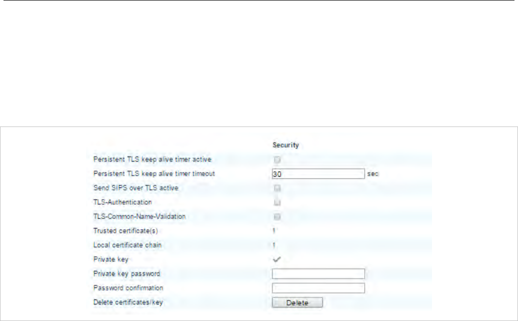
SIP-DECT OM System Manual
74
• Warning tone: Enables or disables warning tone on incoming call. A short ringtone is played if there
are no active calls. If there is an active call in a “barge in” situation, the ringing will be in-band
• Allow barge in: Allows/disallows “barge-in” on existing calls.
5.4.3.8 Security
You can set security-specific settings in the Security section.
• Persistent TLS keep alive timer active: When enabled and “Persistent TLS” is selected as transport
protocol, the OMM sends out keep alive messages periodically to keep the TLS connection open.
• Persistent TLS keep alive timer timeout: Specifies the time pattern, in seconds, in which the OMM
sends out keep-alive messages. Valid values are “10” to “3600”. Default is “30” seconds.
• Send SIPS over TLS active: When enabled, and “TLS” or “Persistent TLS” is selected as transport
protocol, the OMM uses SIPS URIs in the SIP signaling. Default is “ON”.
• TLS-Authentication: When enabled and “TLS” or “Persistent TLS” is selected as transport protocol,
the OMM validates the authenticity of the remote peer via exchanged certificates and the configured
“Trusted certificates”. Default is “ON”.
• TLS-Common-Name-Validation: When enabled and “TLS authentication” is selected, the OMM
validates the “Alternative Name” and “Common Name” of the remote peer certificate against the
configured proxy, registrar and outbound proxy settings. If there is no match, an established TLS
connection will be closed immediately.
• Trusted certificate(s): The number of imported trusted certificates (read-only).
• Local certification chain: Indicates the number of imported certificates in the local certificate chain
(read-only).
• Private key: Indicates whether the OMM has a private key file (read-only).
• Delete certificates/key: Allows deletion of all certificates and the local key.
5.4.3.9 Certificate server
Set the parameters on the Certificate server tab to automatically import Trusted, Local Certificates and a
Private Key files from an external server for SIP signaling.
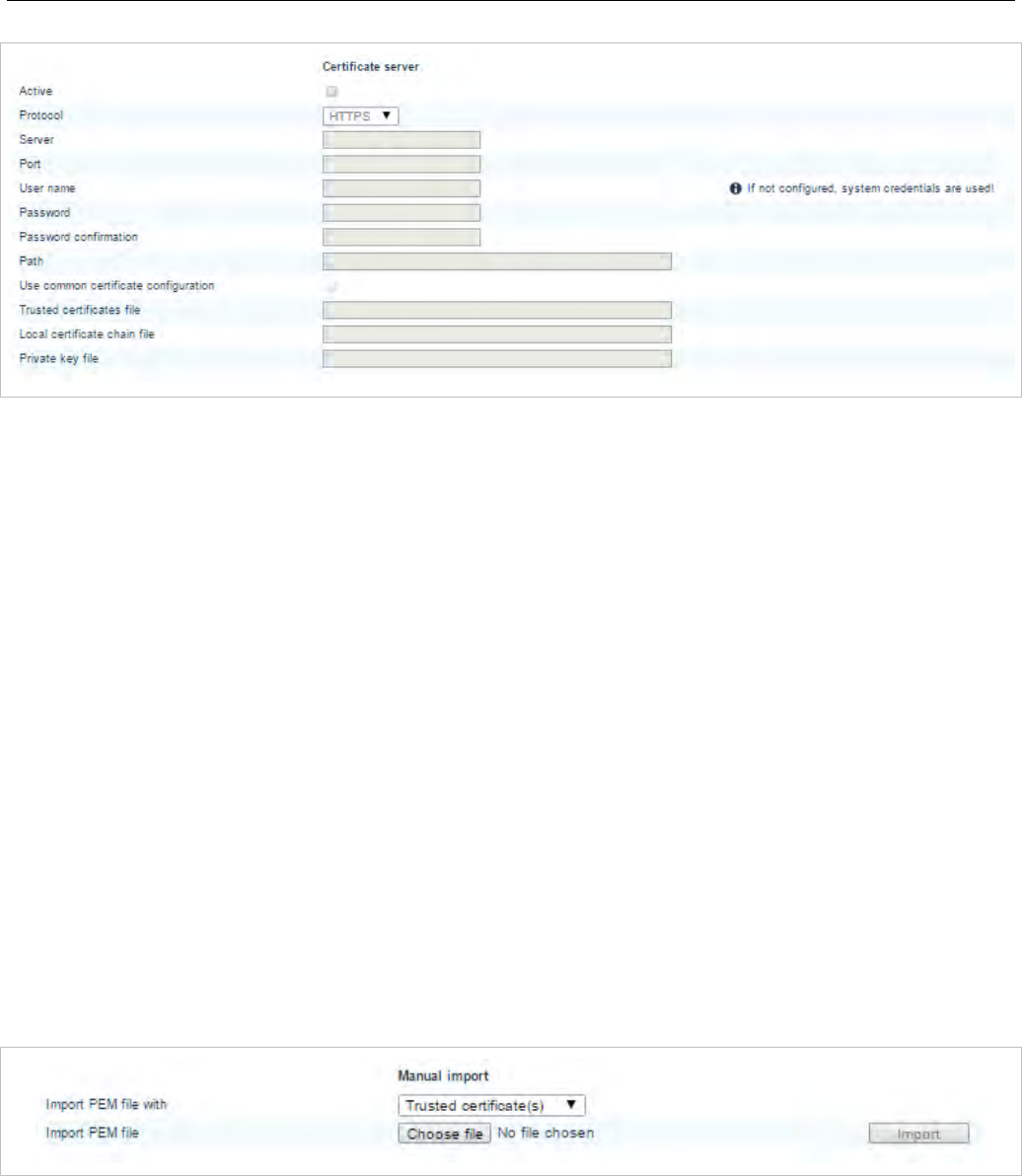
OMM Web Service
75
• Active: Enables the feature.
• Protocol: Specifies the preferred protocol (FTP, TFTP, FTPS, HTTP, HTTPS, SFTP)
• Server: Specifies the name or IP address of the external file servedr.
• User name: Specifies the user name to authenticate against the external file server.
• Password: Specifies the password to authenticate against the external file server.
• Password confirmation: Confirms the password to authenticate against the external file server.
• Path: Specifies the path on the file server to the certificate files.
• Trusted certificate file: Specifies the name of the PEM file on the specified server, including the
trusted certificates.
• Local certificate file: Specifies the name of the PEM file on the external server including the local
certificate or a certificate chain.
• Private key file: Specifies the name of the PEM file on the external server including the local key.
• Port: Specifies the certificate server’s port number.
• Use default port: If selected, the default port associated with the selected protocol is used.
• Use common certificate configuration: Enables the use of the system-wide certificate validation
settings, as configured on the System -> Provisioning -> Certificates page (see section 5.4.2.5).
5.4.3.10 Manual import
Set the parameters for manual import of certificate keys.
• Import PEM file with: Allows selection of the kind of certificate/key to be imported.
• Import PEM file: Specifies the file to be imported.
• Import: Triggers an import of the file
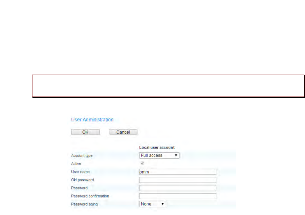
SIP-DECT OM System Manual
76
5.4.4 “USER ADMINISTRATION” MENU
After initial installation or after removing the configuration file, the OMM Web service is accessible via a
built-in user account with user “omm” and password “omm”.
If the default built-in user account is active, the administrator must change the default account data of the
“Full access” and “Root (SSH only)” account. The meaning of the different account types is described in
section 7.17.1.
Please note: The OMM forces you to change the default account data. As long as the
passwords are unchanged, the OMM will not allow any other configuration.
These settings are case sensitive and can be changed on the User administration web page.
• Account type: Select the account type you wish to change.
• Active: This setting applies to the Read-only access account. Using this account, a user is not
allowed to configure any item of the OMM installation. The account can be deactivated.
• User name: If desired, enter a new user name.
• Old password: Related to the “Full Access Account”, to change the password the old password must
be typed in again.
• Password, Password confirmation: Enter the appropriate data in these fields.
The OMM has several rules to check the complexity of the new password. A new password will not be
accepted if:
– the new password is not five or more characters long
– the new password does not contain characters from at least three of the following groups: lower
case, upper case, digits or other characters
– the new password has 50% or more of the same character ('World11111' or 'W1o1r1l1d1')
– the new password contains one of the following items (either upper or lower case as well as forward
or backward):
– account name
– host name (IP address)
– old password
– some adjoining keystrokes (e.g. 'qwert')
• Password aging: A timeout for the password can be set. Select the duration, the password should be
valid.
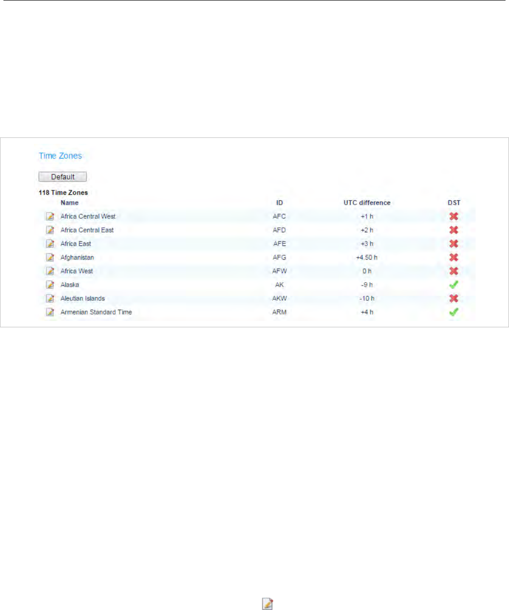
OMM Web Service
77
5.4.5 “TIME ZONES” MENU
Note: This menu is only available if the OMM resides on an RFP.
On the Time zones page, the OMM provides all available time zones. They are set with their known
daylight savings time rules adjusted to the Universal Coordinated Time (UTC) per default. The difference
to the UTC time is shown in the UTC difference column. In case of a configured daylight savings time
rule (DST column) this is also marked for each time zone.
The date and time are provided by the OMM to the Mitel 142 and Mitel 600 DECT phones if the DECT
phone initiates a DECT location registration. This will be done in the following cases:
• subscribing to the OMM
• entering the network again after the DECT signal was lost
• power on
• silent charging feature is active at the phone and the phone is taken out of the charger
• after a specific time to update date and time
The following tasks can be performed on the Time zones page:
• changing the time zones (see section 5.4.5.1)
• resetting time zones (see section 5.4.5.2)
5.4.5.1 Changing Time Zones
It is possible to change the time zone rules for maximal five time zones. Changed rules are marked with
a bold time zone name in the table. The changes are saved in the configuration file and are restored
after each OpenMobility Manager startup.
1 To change the settings of a time zone, click on the icon left behind the time zone entry.
The Configure time zone dialog opens.
2 You can change the standard time and the daylight savings time (DST) of a time zone. If the time
zone has no DST, only the UTC difference can be configured. For the DST both points of time (begin
of standard time and begin of daylight savings time) must be specified exactly. Therefore a certain
day in the month or a certain week day in a month can be used. See the following screenshot as an
example:
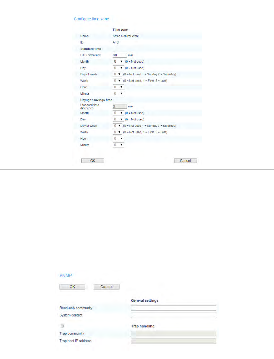
SIP-DECT OM System Manual
78
5.4.5.2 Resetting Time Zones
To reset individual time zone settings, press the Default button on the Time zones web page. This sets
all time zones back to the default values and deletes the changed time zone rules in the configuration
file.
5.4.6 “SNMP” MENU
To manage a larger RFP network, an SNMP agent is provided for each RFP. This will give alarm
information and allow an SNMP management system (such as “HP Open View”) to manage this network.
On the SNMP page of the OMM Web service you configure the SNMP service settings.
You can configure the following SNMP parameters using the OMM web service:

OMM Web Service
79
General settings
• Read-only community: The SNMP community string forms a password that is sent by the SNMP
management system when querying devices. The query is answered only if the SNMP community
string matches. You may use “public” as a default keyword for read-only access.
• System contact: Enter a descriptive text that typically is displayed in the SNMP management
software.
Trap handling
Activate the checkbox behind the Trap handling section to enable this feature.
• Trap community: This community string is used if the SNMP agent informs the SNMP management
system about events (traps).
• Trap host IP address: Enter the IP Address that the SNMP agent uses to send traps.
Further notes
• The RFP needs an initial (one-time) OMM connection to receive its SNMP configuration. In case of a
reset, this configuration does not change. Changing the SNMP configuration on the OMM forces all
agents to be reconfigured.
• The agent does not support MIB-II write access, SNMPv2-MIB read/write access, NET-SNMP-MIB
read/write access, NET-SNMP-AGENT-MIB read/write access and SNMPv3.
• For background information on using SNMP with the SIP-DECT system see section 7.19.
5.4.7 “DB MANAGEMENT” MENU
The database management (DB) menu allows flexible backup and restore management of the OMM
database. The OMM database contains all configuration settings which are configurable via the OMM
Web service interface.
The OMM database can be
• manually imported from the Web browser’s file system or from an external server (see section
5.4.7.1),
• manually exported to the Web browser’s file system or to an external server (see section 5.4.7.2),
• automatically exported to an external server when configuration modifications are done (see section
5.4.7.3).
Note: The OMM database is saved in a compressed file in a proprietary
format. Any modification of this file outside the OMM is not
allowed.
The following protocols for the transport to or from an external server are supported:
FTP, TFTP, FTPS, HTTP, HTTPS, SFTP.
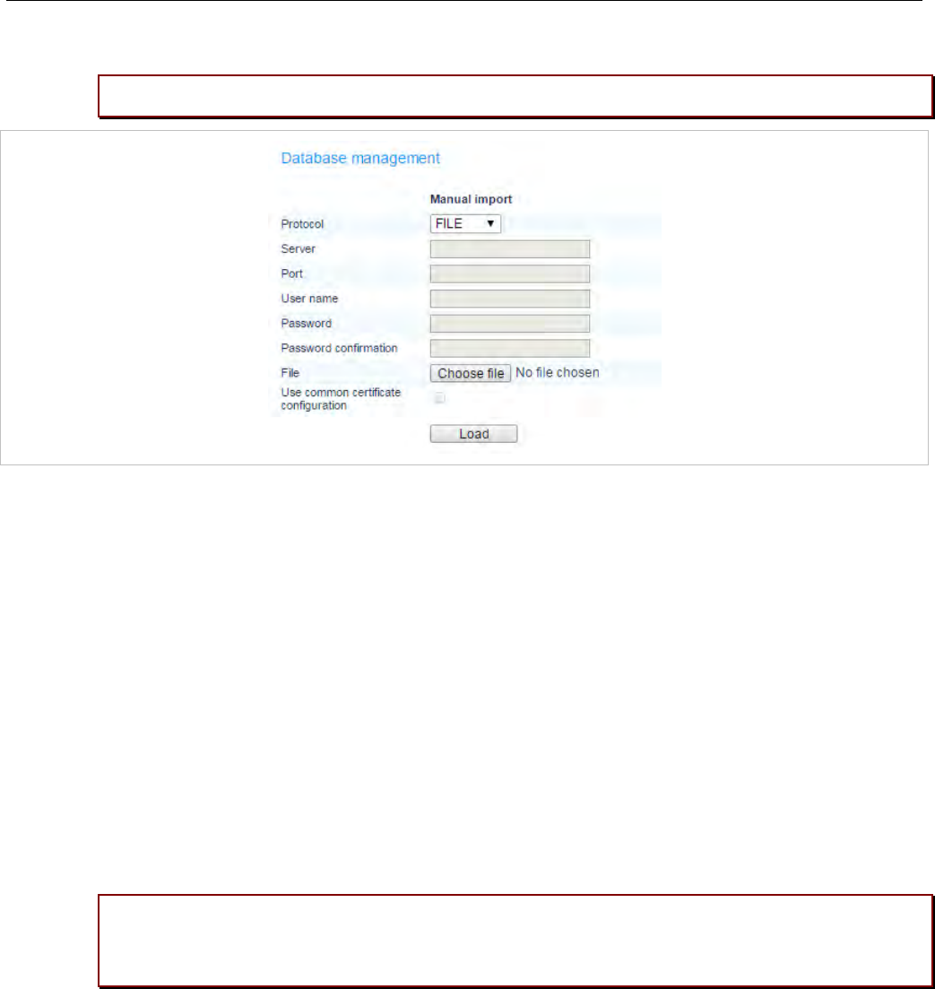
SIP-DECT OM System Manual
80
5.4.7.1 Manual Database Import
Please note: A manual import of a database results in a reset of the OMM.
In the Manual import section of the Database management page enter the following:
1 Protocol:
– To import a database from the Web browser’s file system the protocol FILE must be selected.
– To import a database from an external server select the preferred protocol (e.g. HTTP).
2 Server: IP address or the name of the external server.
3 User name, Password (in case of import from an external server): If necessary, enter the account
data of the server.
4 File: Path and file name which include the OMM database. If you have selected the FILE protocol, the
Browse button is displayed and you can to select the file from the file system.
5 Use common certificate configuration: Enables the use of the system-wide certificate validation
settings, as configured on the System -> Provisioning -> Certificates page (see section 5.4.2.5).
6 Press the Load button.
Before the OMM accepts the database, a validation check is performed. If the database is verified as
valid, the OMM will be reset to activate the new database.
Please note: After the reset, all configuration in the restored database takes effect with the
exception of the user account settings. The user account settings can be only modified
locally via the OMM Web service and are never restored by a database import.
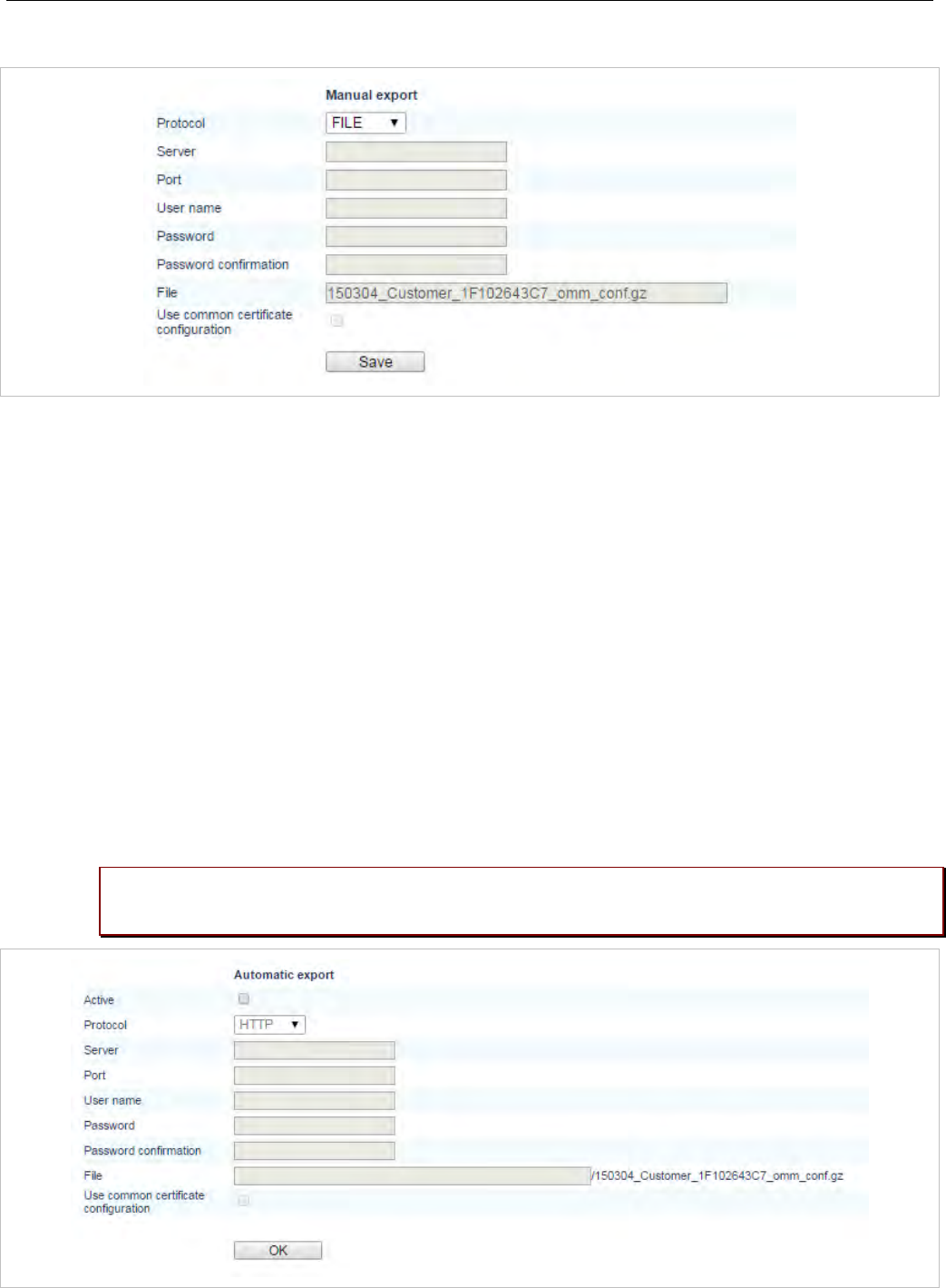
OMM Web Service
81
5.4.7.2 Manual Database Export
In the Manual export section of the Database management page enter the following:
1 Protocol: Select the preferred protocol. If you want to export the database to the Web browser’s file
system, select the FILE setting.
2 Server: Enter the IP address or the name of the server.
3 User name, Password: If necessary, enter the account data of the server.
4 File: Enter the path and filename where the database is to be saved.
5 Use common certificate configuration: Enables the use of the system-wide certificate validation
settings, as configured on the System -> Provisioning -> Certificates page (see section 5.4.2.5).
6 Press the Save button.
5.4.7.3 Automatic Database Export
The automatic database export feature allows an automatic database backup to an external server for
each configuration modification. If this feature is activated, the OMM transfers a backup file to a
configured external server any time configuration changes occur (e.g. DECT phone subscription). The
backup file overwrites any existing backup files.
Please note: Synchronization with an NTP server is mandatory for an automatic database
export. For NTP server configuration see section 7.5.4 and section 7.6.
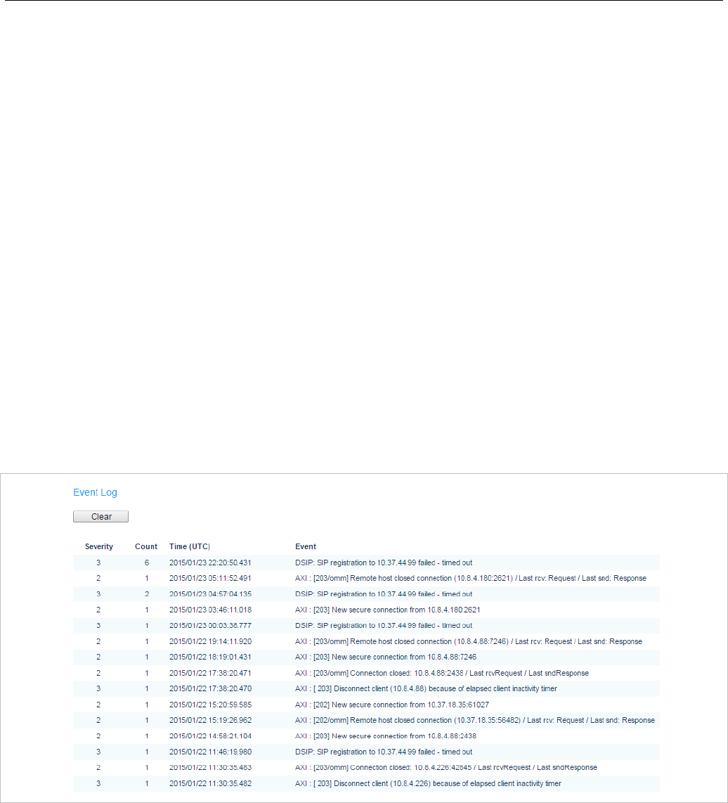
SIP-DECT OM System Manual
82
In the Automatic export section of the Database management page enter the following:
1 Active: Activate this option to enable the automatic export feature.
2 Protocol: Select the preferred protocol.
3 Server: Enter the IP address or the name of the server.
4 Port: Enter the port of the server.
5 User name, Password: If necessary, enter the account data of the server.
6 File: Enter the path and filename where the database is to be saved.
The OMM writes the database into a file on the external server with following name convention:
<yymmdd>_<system_name>_<PARK>_omm_conf.gz
If the system name contains non-standard ASCII character then these character are replaced by “_”.
7 Use common certificate configuration: Enables the use of the system-wide certificate validation
settings, as configured on the System -> Provisioning -> Certificates page (see section 5.4.2.5).
8 Press the OK button.
5.4.8 “EVENT LOG” MENU
The Event log page displays important event information on OMM system functions, e.g. security
aspects. A more detailed system log is available by configuring the Syslog function in the System
settings menu (see section 5.4.1.9).
To clear the display, press the Clear button.
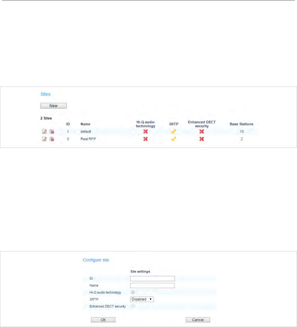
OMM Web Service
83
5.5 “SITES” MENU
DECT base stations can be grouped into different sites. A site consists of the following parameters:
• ID: Identification number of the site.
• Name: The name of the site.
• Hi-Q Audio Technology, SRTP, Enhanced DECT Security: Indicates whether (one of) these
features are enabled for the site.
• Base stations: The number of base stations assigned to the site.
The following tasks can be performed:
• create a new site (see section 5.5.1)
• edit a site (see section 5.5.2)
• delete a site (see section 5.5.3)
5.5.1 CREATING A NEW SITE
1 On the Sites page press the New button.
The Configure site dialog opens.
2 ID: Enter the identification number of the site. A value between 1 and 250 is possible. If no value is
given, the OMM selects the next free ID.
3 Name: Enter the name of the site.
4 Hi-Q audio technology, SRTP, Enhanced DECT security: Enable or disable these capabilities.
– In sites where these features are enabled, only RFP 35/36/37 IP and RFP 43 WLAN are supported.
– In sites where these features are disabled, you can mix new RFP types with older RFP 32/34 and
RFP 42 WLAN base stations.
5 Press the OK button to save your changes.
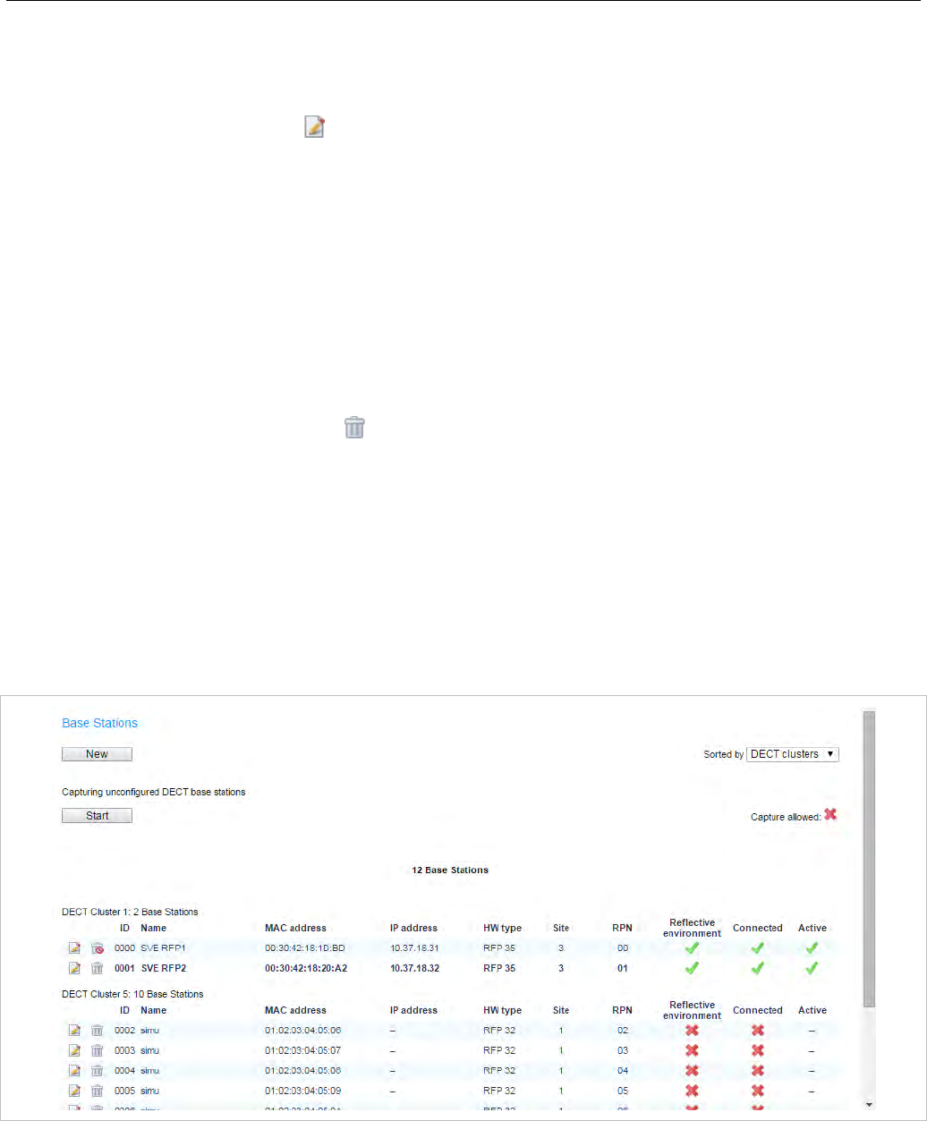
SIP-DECT OM System Manual
84
5.5.2 EDITING A SITE
You can change the name of an existing site:
1 On the Sites page click on the icon left behind the site entry.
The Configure site dialog opens.
2 Change the site name.
3 Press the OK button.
5.5.3 DELETING A SITE
Note: Only sites without assigned base stations can be deleted. At
least one site must remain, so the last site cannot be deleted.
To delete an existing site:
1 On the Sites web page click on the icon left behind the site entry.
The Delete site dialog opens.
2 Press the Delete button.
5.6 “BASE STATIONS” MENU
All configured base stations are listed on the Base stations page. The base stations are sorted by their
Ethernet (MAC) addresses.
You can select a sorting criterion for the RFP table. In the Sorted by field, select the criterion:
• DECT clusters: The base stations are sorted by clusters. All used clusters are displayed in the
navigation bar on the left side. The OMM base station is marked with a bold font.
• WLAN profiles: The base stations are sorted by WLAN profile (see section 5.8).
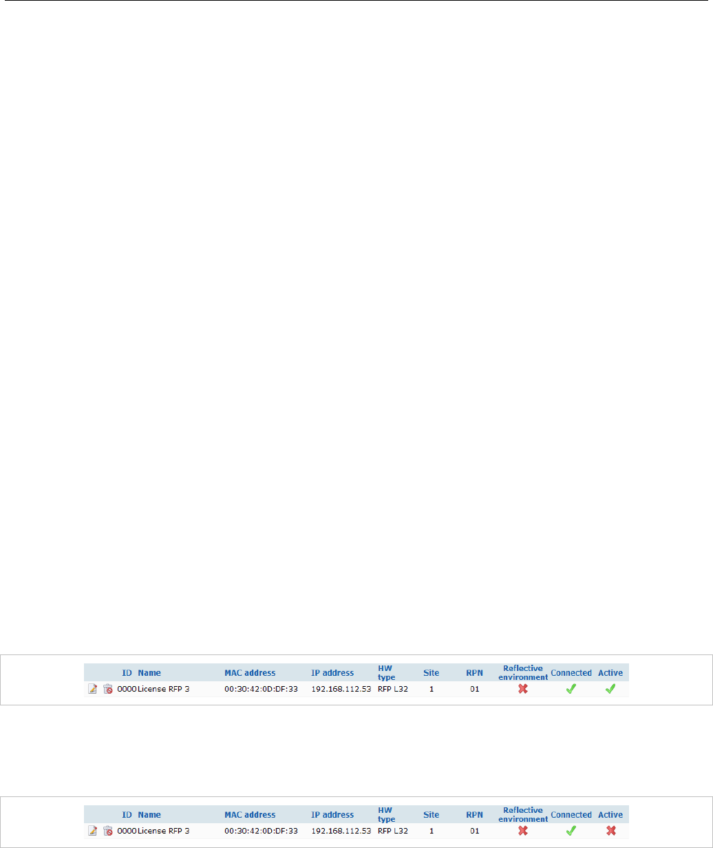
OMM Web Service
85
• Sites: The base stations are sorted by sites (see section 5.5). All used sites are displayed in the
navigation bar on the left side. The OMM base station is marked with a bold font.
The table provides information on all configured base stations and their status in several columns:
• ID: An internal number that is used to manage the base station.
• Name: Indicates the base station's name (see section5.6.3).
• MAC address: Indicates the base station's MAC address (see section5.6.3).
• IP address: Shows the current IP address of the RFP. The IP address may change over time by
using dynamic IP assignment on the DHCP server.
• HW type: When the base stations connect to the OMM, they submit their hardware type. The
hardware type is displayed in this column. If an error message is indicated in this column, there is a
mismatch between the base station and the OMM software version (see section 5.6.2).
• Site: Indicates the site the base station is assigned to (see section 5.5).
• RPN: Shows the Radio Fixed Part Number that is currently used by the RFP.
• Reflective environment: Indicates if the base station is operated in a reflective environment (see
section 5.6.3).
• Connected: Indicates if the base station is connected to the OMM (see section 5.6.1).
• Active: Indicates if the base station is active (see section 5.6.1).
The following tasks can be performed on the Base stations page:
• create and change base stations (see section 5.6.3),
• capture base stations (see section 5.6.4),
• delete base stations (see section 5.6.5).
5.6.1 BASE STATION STATES
For each base station the state of the DECT subsystem is displayed. These states are:
Synchronous
The RFP is up and running. The RFP recognizes and is recognized by other RFPs in its cluster through
its air interface and delivers a synchronous clock signal to the DECT phones.
Asynchronous
The RFP has not been able to synchronize to its neighbors yet. No DECT communication is possible.
But nevertheless the RFP has already been able to connect to the OMM. This phase should usually last
only for a few seconds after starting up the RFP or the OMM. If this state lasts longer this is an indication
for a hardware or network failure.
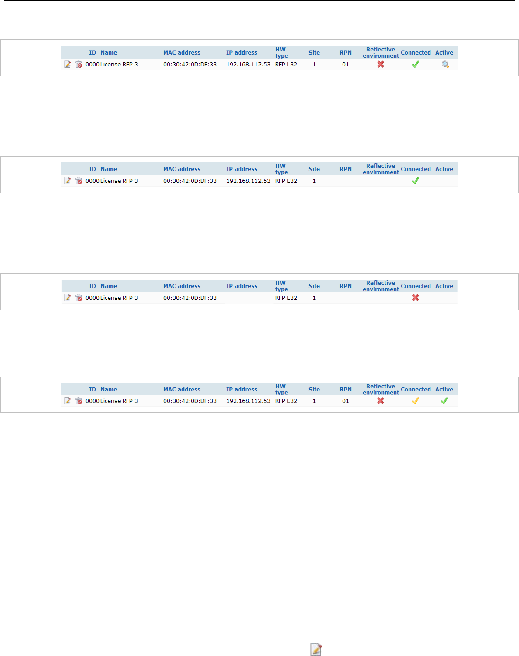
SIP-DECT OM System Manual
86
Searching
The RFP has lost synchronization to its neighbors. No DECT communication is possible. This phase
should usually last only for a few seconds after starting up the RFP or the OMM. If this state lasts longer
or is re-entered after being in a synchronous state this is an indication for a bad location of the RFP.
Inactive
The RFP has connected to the OMM but the air interface has not been switched on yet. For any RFP
with activated DECT functionality this phase should last only for a few seconds after starting up the RFP.
If this state lasts longer this may indicate a hardware failure.
Not connected
The RFP was configured but has not connected to the OMM yet. Therefore the IP address column is
empty.
Software Update available
The RFP is connected to the OMM. The OMM has found new software on the TFTP server. The RFP is
waiting for the OMM to initiate a reboot. In the meantime is the RFP fully operational.
5.6.2 OMM / RFP SOFTWARE VERSION CHECK
When the DECT base stations connect to the OMM, they submit their software version. If this version
differs from the OMM software version and the versions are incompatible, the RFP connection attempt is
rejected. This could happen when using several TFTP servers with different OpenMobility software
versions. In this case, the RFP is marked with an error message. Moreover a global error message is
displayed on the RFP list web page if at least one version mismatch has been found.
5.6.3 CREATING AND CHANGING BASE STATIONS
1 To configure a new RFP, click the New button on the Base Stations page.
To change the configuration of an existing RFP click on the icon left beside the base station entry.
The New base station (or the Configure base station) dialog opens.
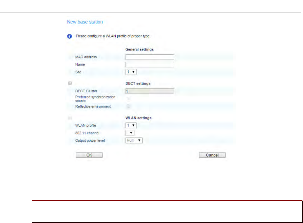
OMM Web Service
87
2 Configure the base station (see parameter descriptions below).
3 Click OK.
Please note: DECT regulatory domain, WLAN regulatory domain and WLAN profile must be
configured first. Otherwise DECT and/or WLAN cannot be enabled.
The following parameters can be set in the New base station and the Configure base station dialogs:
General settings
• MAC address: Each RFP is identified by its unique MAC address (6 bytes hex format, colon
separated). Enter the MAC address (as it appears on the back of the base station chassis).
• Name: For easier administration each RFP can be associated with a location string. The location
string can hold up to 20 characters.
• Site: If several sites exist (see section 5.5), select the site the RFP is assigned to.
DECT settings
The DECT functionality for each RFP can be switched on/off.
• DECT cluster: If DECT is active the RFP can be assigned to a cluster.
• Preferred synchronization source: Activate this checkbox if the RFP should be used as
synchronization source for the other RFPs in the cluster. For background information on RFP
synchronization see section 7.2.
• Reflective environment: Within areas containing lot of reflective surfaces (e.g. metal or metal coated
glass) in an open space environment the voice quality of a DECT call can be disturbed because of
signal reflections which arrive on the DECT phone or RFP using multipath propagation. Calls may
have permanent drop outs while moving and high error rates on the RFPs and DECT phones.

SIP-DECT OM System Manual
88
For such environment Mitel has developed the DECT XQ enhancement into the RFP base stations
and the Mitel 600 DECT phones family. Using this enhancement by switching the Reflective
environment flag on might reduce drop outs and cracking noise.
As soon as Reflective environment is switched on, the number of calls on an RFP is reduced to
4 calls at the same time.
Please note: The RFPs and DECT phones use more bandwidth on the Air Interfaces if the
“Reflective environment“ attribute is switched on. Therefore this is used when problems
caused by metal reflections are detected.
WLAN settings
The WLAN section applies to RFPs of the type “RFP 42 WLAN” and “RFP 43 WLAN” only. For details
about WLAN configurations please see section 7.18.
RFP 42 WLAN and RFP 43 WLAN have different WLAN parameters, which are configurable in the RFP
configuration dialog.
• Activation check box: Enables or disables the WLAN function for this RFP.
• WLAN profile: Select the desired profile from the list. This applies all settings made in the respective
WLAN profile to the current RFP. For information on configuring WLAN profiles see section 5.8.1.
Please note: WLAN settings are only configurable if the RFP has been connected at least
once to detect the hardware type and a proper WLAN profile is configured (see also
section 5.8.1). WLAN cannot be enabled in the New DECT base station dialog if the
hardware type is unknown.
The following settings are not applied by the WLAN profile. Configure these settings for each RFP
individually.
• Antenna diversity (RFP 42 WLAN only): This option should generally be activated so that the AP
(Access Point) can automatically select the antenna with the best transmission and reception
characteristics.
• Antenna (RFP 42 WLAN only): If Antenna diversity is switched off, this setting determines the
antenna that is used for transmitting or receiving WLAN data.
• 802.11 channel: Determines the WLAN channel used by the current RFP. The channel numbers
available are determined by the WLAN Regulatory domain setting on the System settings page.
• Output power level (default: “Full”): Determines the signal power level used by the RFP to send
WLAN data. You may limit the power level to minimize interferences with other WLAN devices. The
actual power level is also capped by the WLAN Regulatory domain setting on the System settings
page.
• HT40 (RFP 43 WLAN only): High throughput mode with 40 MHz bandwidth increases data rate up to
300 MB/s.
5.6.4 CAPTURING BASE STATIONS
Base stations that are assigned to the OMM by DHCP options or OM Configurator settings may connect
to the system.
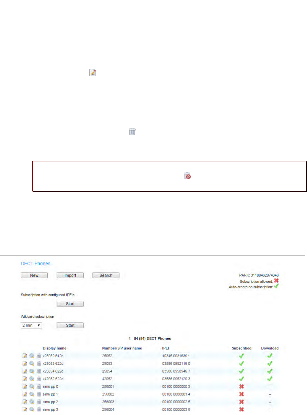
OMM Web Service
89
1 On the Base Stations page, press the Start button below the “Capturing unconfigured DECT base
stations” caption.
The page is updated with the MAC addresses of those base stations that attempted to register with
the OMM (unregistered RFPs).
Note: These entries are not actually stored, and are lost after an OMM
reset.
2 By clicking on the edit icon of the appropriate base station, you can add further data and store the
base station (see section 5.6.3).
5.6.5 DELETING RFPS
To delete an existing RFP:
1 On the Base Stations page, click on the icon left beside the RFP entry.
The Delete base station? dialog opens showing the current configuration of this RFP.
2 Click the Delete button.
Please note: The RFPs bound to a license (License RFPs) cannot be deleted. The License
RFPs are displayed in the list with a license icon instead of the trash icon. For further
information on licenses see section 4).
5.7 “DECT PHONES” MENU
The DECT Phones page provides an overview of all configured DECT phones sorted by their number.
To keep the list concise, the complete list is split up into sub lists containing up to 100 DECT phones.
You can move back and forth in increments of 100 DECT phones.
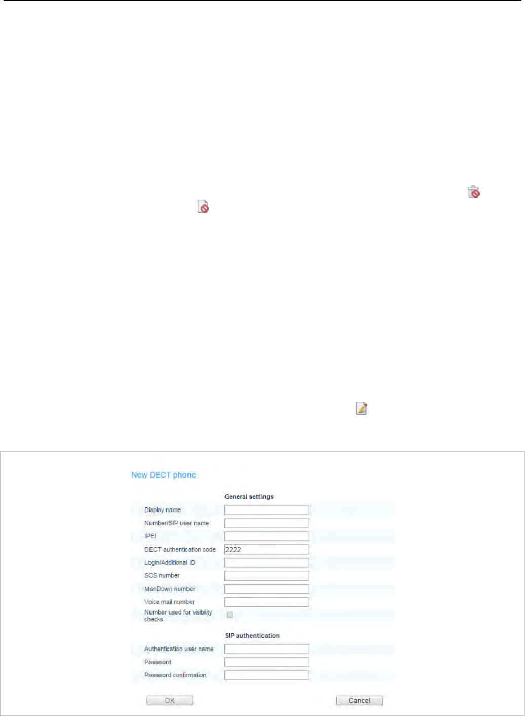
SIP-DECT OM System Manual
90
The table provides information on the DECT phones and their status in several columns:
• Display name: Indicates the DECT phone name.
• Number/SIP user name: Indicates the internal call number of the DECT phone.
• IPEI: Indicates the DECT phone IPEI.
• Subscribed: Indicates if the DECT phone is subscribed to the system.
• Download: This column is only displayed if the “Download over Air” feature is started successfully
and provides information about the download status of the DECT phone software (see section 7.20).
Note: All DECT phone data that are configured as unbound (split into
DECT phone and user data) are also listed at the OM Web
service when a user is logged in at the DECT phone, but they
cannot be deleted or changed. This is indicated by the and
icons. Unbound DECT phones where no user is logged in are
not displayed on the DECT phones page.
The following tasks can be performed on the DECT Phones page:
• create and change DECT phones (see section 5.7.1)
• import DECT phone configuration files (see section 5.7.2),
• subscribe DECT phones (see section 5.7.3)
• delete DECT phones (see section 5.7.4)
• search within the DECT phone list (see section 5.7.5)
5.7.1 CREATING AND CHANGING DECT PHONES
1 To configure a new DECT phone, click the New button on the DECT phones page.
To change the configuration of an existing DECT phone click on the icon left beside the DECT
phones entry.
The New DECT phone or the Configure DECT phone dialog opens.

OMM Web Service
91
2 Configure the DECT phone (see parameter descriptions below).
3 Press the OK button.
The following parameters can be set in the New DECT phone and the Configure DECT phone dialog:
General settings
• Display name: The name parameter represents the SIP Display Name field. This parameter is
optional but recommended.
• Number/SIP user name: The number is the SIP account number or extension for the DECT phone.
• IPEI: This optional setting is the DECT phone IPEI number. On a Mitel DECT 142 / Mitel 142d DECT
phone, the IPEI can be found via the following path of the DECT phone menu: Main menu > Phone
settings > System. On a Mitel 600 DECT phone, the IPEI can be found in the System DECT phone
menu. Consult the DECT phone’s user guide for further information.
• DECT authentication code: The DECT authentication code is used during initial DECT subscription
as a security option and can be set here for each DECT phone separately (DECT phone-specific
DECT authentication code). This parameter is optional. If no DECT phone-specific DECT
authentication code is set, the system-wide DECT authentication code is used.
• Login/Additional ID: The additional ID can be used as a mean for data search within wildcard
subscription (because of the IPEI is not configured which selects the data otherwise).
• Delete subscription: This option is only available when configuring an existing DECT phone (in the
Configure DECT phone dialog). If this option is selected, the DECT phone will be unsubscribed.
• SOS number, ManDown number: SOS and ManDown are calling numbers which will be
automatically called as soon as an SOS or ManDown event happens. If no individual SOS or
ManDown number is configured for a DECT phone, the number of the appropriate alarm trigger will be
used as a system-wide calling number in case of a SOS or ManDown event. Please see /31/ for
details.
• Voice mail number: The voice mail number is the number which will be automatically called as soon
as a voice mail call is initiated on the Mitel 600 DECT phone. If there is no individual voice mail
number configured in this field, then the system-wide voice mail number is used (see also the System
setting menu, section 5.4.1.7). If there is no voice mail number configured (neither the individual nor
the system-wide) or another DECT phone type is used, then the voice mail number must be
configured locally in the DECT phone.
• Number used for visibility checks: Provides phone number or SIP user name used for standby
OMM visibility checks.
SIP authentication
• User name: The SIP Authentication user name is optional but recommended. It represents the name
which will be used during SIP registration and authentication. If no name is given the number will be
used by default.
• Password, Password confirmation: The password will be used during SIP registration and
authentication. Enter the appropriate data in these fields.
5.7.2 IMPORTING DECT PHONE CONFIGURATION FILES
A set of DECT phones can also be configured in a semi-automatic manner by import of a configuration
file.
1 On the DECT Phones page press the Import button.
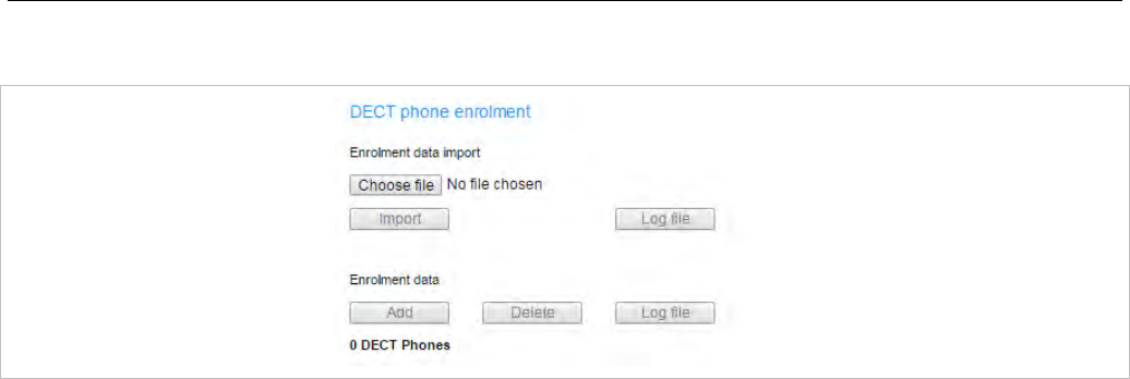
SIP-DECT OM System Manual
92
The DECT phone enrolment page opens.
2 Select your configuration file and press the Import button. For information on the file layout see
section 9.4.1.
3 A parsing protocol can be read, if you press the referring Log file button. All successfully imported
data records are presented in a list:
4 Select the DECT phones you want to add to the OMM database by selecting the appropriate
checkboxes, and click Add.
All successfully stored records are marked green in the Added column.
Failed records are marked with a red star.
5 To read error hints in the referring log file, press the Log file button. Error hints can also be read in a
syslog trace.
6 To remove imported data entries, activate the check box next to the desired entries. Press Delete to
remove the selected entries.
5.7.3 SUBSCRIBING DECT PHONES
Preparation by OMM Web service
After adding a DECT phone configuration to the OMM, the DECT phone must be subscribed. The OMM
must first be enabled to allow subscriptions from DECT phones. This is done by pressing the following
buttons on the DECT Phones page.
• Start button under the “Subscription with configured IPEI” caption (see section 5.7.3.1). This button
enables subscription for the next 24 hours.
• Start button and time interval parameter under the “Wildcard subscription” caption. This button
enables wildcard subscription for the selected time. After expiry the “subscription with configured
IPEIs” is still enabled for 24 hours.
Note: To ease the first installation of a DECT system, the subscription
is enabled permanently while at least one DECT phone (with
IPEI) is set up in the database and no DECT phone is
subscribed. After successful subscription of the first DECT phone
the subscription will still be enabled for 24 hours.
Subscription steps, done by DECT phone
After the DECT phone configuration is complete on the OMM and the OMM is allowing new
subscriptions, each DECT phone must subscribe to the system.

OMM Web Service
93
On each DECT phone, the administrator or user must subscribe to the SIP-DECT system through the
System -> Subscriptions menu. The specific PARK code for the SIP-DECT system should be entered
to subscribe to the system.
Please note: The PARK is displayed in the top-right corner of the DECT Phones page.
Each SIP-DECT deployment has a unique PARK code.
If the administrator configured a global or device-specific DECT authentication code, the
administrator/user must enter in the code before the DECT phone subscribes to the system.
For “wildcard subscription”, an additional ID may be configured (see sub section Wildcard Subscription).
5.7.3.1 Subscription with Configured IPEI
The DECT phone data to be assigned to the subscribing DECT phone are identified by the IPEI. The
identity of a DECT phone (IPEI) is already known by the system before the DECT phone attempts to
subscribe. Unknown DECT phones are not allowed to subscribe in this mode.
To enable subscriptions, click the Start button under the section Subscription with configured IPEIs
caption on the DECT Phones page.
The OMM allows a subscription of configured but not subscribed DECT phones during the next 24 hours.
The administrator must press the Subscribe button again to permit more DECT phones to subscribe to
the SIP-DECT system.
Note: Older DECT phones may not offer the possibility to enter an
access code (AC). You should always subscribe these DECT
phones with configured IPEI to maintain security.
5.7.3.2 Wildcard Subscription
To minimize administration effort, subscription is also possible, if the IPEI is not configured. But because
of the loss of further security by IPEI check, this kind of subscription is only allowed within a short default
time interval of 2 minutes.
To enable subscriptions, press the Start button of the section Wildcard subscription on the DECT
phones page. If necessary, increase the time interval (or refresh subscription permission in time).
The OMM will allow a wildcard subscription during the set time interval. In case of timeout the permission
is lost. Only subscription with IPEI remains allowed within the fixed limit of 24 hours.
To achieve a selection of data during subscription (e.g. the user name being assigned to the DECT
phone), the field “additional ID” can be set in OMM data. If the OMM receives a valid “additional ID”
during subscription, the referring data are assigned to the DECT phone.
If the additional ID is requested for a data record, the DECT phone user must type it. “Additional ID” can
be set within the authentication code menu. Please type the R-Key and type the additional ID.
Please note: The input of the additional ID is only possible with Mitel 142 and Mitel 600
DECT phones. The value is not supported on third party GAP phones. If GAP phones are
going to subscribe wildcard, the first free DECT phone data record without any additional
ID will be assigned.
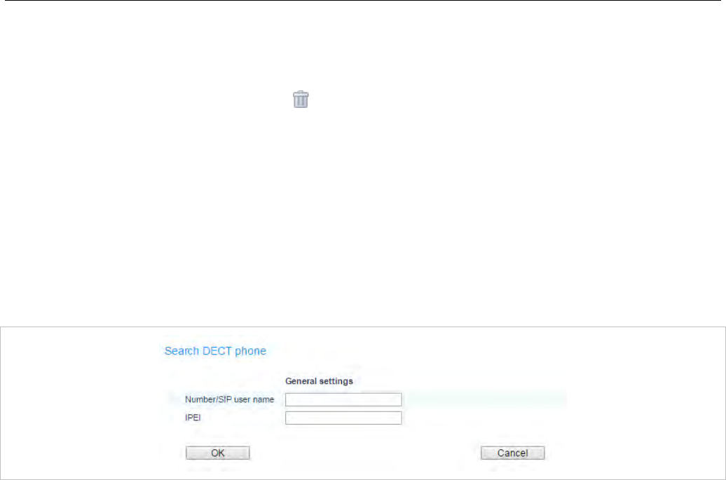
SIP-DECT OM System Manual
94
5.7.4 DELETING DECT PHONES
To delete an existing DECT phone:
1 On the DECT phone page click on the icon left beside the DECT phone entry.
The Delete DECT phone? dialog opens showing the current configuration of this DECT phone.
2 Press the Delete button.
5.7.5 SEARCHING THE DECT PHONE LIST
You can use the search function to search for a specific DECT phone in the DECT phone list. The
search function allows you to find a DECT phone by a given number or IPEI.
1 On the DECT phones page click on the Search button.
The Search DECT phone dialog opens.
2 Enter the DECT phone’s number or IPEI. At least one parameter must be set. The entered number or
IPEI must match exactly with a DECT phone’s number or IPEI. If number and IPEI are given then a
DECT phone must exist in the OMM’s database whose number and IPEI match both otherwise the
search fails.
If a DECT phone with the specified number and/or IPEI was found, a list is displayed with this DECT
phone as the first entry. The search function can also be used to get to the right sub list in one step.
5.7.6 DISPLAYING USER AND DECT PHONE DATA
You can display a summary of user status and DECT phone configuration in a pop-up window on the
DECT Phone page. Click the magnifying glass icon beside a DECT phone entry to view the User/device
status & configuration window.
Note: A configuration and status summary for the DECT phone is also
available on the DECT phone under the Administration menu.
The presentation layout is similar to the OMM Web service
window, but the DECT phone only displays its own data.
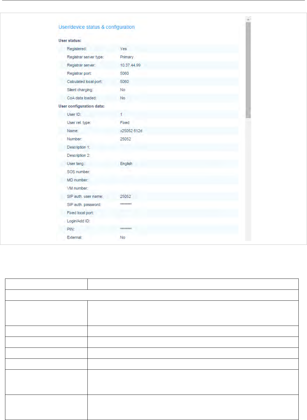
OMM Web Service
95
The following table summarizes the parameters displayed in the User/device status & configuration
window.
Parameter Description
User status
Registered Current SIP user registration status
Yes = registered
No = not registered
Registrar server type Current SIP registrar: Primary or backup SIP registrar (secondary or tertiary)
Registrar server IP address of the SIP Registrar
Registrar port Port number of the SIP Registrar
Calculated local port SIP user’s automatically determined client port
Silent charging Current silent charging state
Yes = in silent charging mode
No = not in silent charging mode
CoA data loaded COA data sent to DECT phone
Yes = data has been sent
No = no data sent

SIP-DECT OM System Manual
96
User configuration data
User Id Internal system identifier for the user
User rel. Type Type of association between the user and the DECT phone. Dynamic or
fixed.
Name User’s name
Number SIP user name or number
Description 1 Additional textual description for a user (e.g., department or function)
Description 2 Additional textual description for a user (e.g., department or function)
User lang. Language setting on the DECT phone
SOS number Emergency number to be dialed when the SOS key has been pressed
MD number Emergency number to be dialed when a sensor alarm (Mitel 600 DECT
phone) has been initiated
VM number Voice mail number (dialed by a long press of ‘1’ key on the Mitel 600 DECT
phone)
SIP auth. user name SIP authentication user name
SIP auth. password SIP authentication password
Fixed local port SIP user’s configured fixed client port (used for SIP registration)
Login/Add ID ID used for user identification during login procedure at the DECT phone OR
ID used for wildcard subscription during DECT phone subscription procedure
PIN PIN used for user identification during login procedure at the DECT phone
“*******” = a PIN is set,
empty = no PIN is set
External User data provided by an external provisioning server (<user>.cfg)
Yes = user data imported from a server
No = user data only stored internally in the OMM DB
VIP To guarantee a minimum blackout for a very important person (e.g.
emergency user) the SIP (re-)registration of such people can be prioritized.
Yes = prioritized
No = not prioritized
Visibility checks The OMM standby feature uses an existing SIP account to check the
availability of the registrar.
Yes = this account is used
No = this account is not used
Sending messages User’s permissions to send text messages using the Mitel 600 DECT phone
Yes = user is authorized to send text messages
No = user is not authorized to send text messages
Sending vCards User’s permissions to send vCards using the Mitel 600 DECT phone
Yes = user is authorized to send vCards
No = user is not authorized to vCards
Receiving vCards Indicates whether the user accepts received vCards
Yes = incoming vCards are accepted
No = incoming vCards are not accepted
Video stream perm. User’s permissions to access video using the Mitel 600 DECT phone
Yes = user is authorized to access video

OMM Web Service
97
No = user is not authorized to access video
Locate User’s permissions to locate other users using the Mitel 600 DECT phone
Yes = user can locate other users
No = user cannot locate other users
Tracking Tracking forces the Mitel 600 DECT phone to indicate every change of the
DECT base station even in idle state
Yes = tracking is active
No = tracking is inactive
DECT locatable Permission to locate the user (i.e., through the SIP-DECT locating solution)
Yes = locating the user is permitted
No = not permitted
Keep personal dir. The local directory of the Mitel 600 DECT phone is usually the user’s personal
directory and is cleared at logout. If deleting the directory content is not
desirable, this option can be set
Yes = local directory is not cleared
No = local directory is cleared
Logout on charging A user logout can be performed automatically when the Mitel 600 DECT
phone is placed in the charger cradle
Yes = automatic logout when put in charger
No = no automatic logout
Forward mode Mode of Call diversion or Call forwarding (Off, Immediately, Busy, No answer,
Busy & no answer)
Forward time Time delay in seconds before the incoming call is redirected.
Forward dest. Destination of the redirected call
Hold ring back time Time in minutes after which the user wants to be reminded of the connection
on hold
0 = Off, no reminder
Call waiting disabled An incoming call is signaled in-band if the user is otherwise engaged (Call
waiting). This feature can be disabled
Yes = call waiting is disabled
No = call waiting feature is active
Auto answer Enables or disables auto-answer on incoming calls. If auto answer is enabled,
the DECT phone plays a tone to alert the user before answering the call. If
auto answer is disabled, the DECT phone treats the incoming call as a normal
call.
Microphone mute Enables or disables microphone muting when incoming calls are
automatically answered.
Warning tone Enables or disables a warning tone to play when the DECT phone receives
an incoming call on an active line. A short ringtone is played if there are no
active calls. If there is an active call in a “barge in” situation, the ringing will be
in-band.
Allow barge in Allows/disallows how the DECT phone handles incoming calls while the
DECT phone is on an active call. When enabled an incoming call takes
precedence over an active call, by placing the active call on hold and
automatically answering the call. When disabled the DECT phone treats an
incoming call like a normal call.
Monitoring mode SIP-DECT supports a “User Monitoring” feature to check the availability of a
user to receive calls or messages.
On = monitoring feature is active

SIP-DECT OM System Manual
98
Off = monitoring feature is not activated
Conference server type User-specific setting of the conference service to be used for three-way
conferencing
None = three-way conferencing is disabled
Global = OMM system setting is used (default)
Integrated = integrated conference server is used
Conference server URI URI for the external conference server
Use CoA profile ID of the CoA (Central DECT phone configuration over air) profile
Device status
IPEI International Portable Equipment Identifier (globally unique identifier of the
DECT phone)
HW type Hardware type of 600 DECT phone or 142d otherwise “unknown”
SW version Version of the software on the Mitel 600 DECT phone
Subscribed Subscription status of the DECT phone
Yes = DECT phone is subscribed
No = DECT phone is not subscribed
Encryption DECT encryption status
Yes = Encryption is enabled
No = Encryption is disabled
Capability ”Messaging” Messaging capability of the DECT phone
Yes = DECT phone supports messaging
No = DECT phone does not support messaging
Capability ”Enh. Locating” Enhanced locating capability of the DECT phone
Yes = DECT phone supports enhanced locating
No = DECT phone does not support enhanced locating
Capability ”Video” Video capability of the DECT phone
Yes = DECT phone supports video
No = DECT phone does not support video
Capability ”CoA profile” CoA capability (Central DECT phone configuration over air) of the DECT
phone
Yes = DECT phone supports CoA
No = DECT phone does not support CoA
Device auto-created Auto-creation occurs when the DECT phone data set is automatically
generated in the OMM’s database at subscription time. No administrative task
is required onthe SIP-DECT system to subscribe a DECT phone in this auto-
create mode.
Yes = DECT phone has been subscribed in auto-create mode
No = DECT phone has not been subscribed in auto-create mode
Default CoA profile loaded A default CoA profile (Central DECT phone configuration over air) can be sent
to a 600 DECT phone
Yes = a default profile was sent
No = no default profile was sent
Device configuration data
Device ID Internal system identifier for the DECT phone

OMM Web Service
99
5.8 “WLAN” MENU
The WLAN menu allows you to manage the wireless LAN function of all WLAN capable RFPs that are
connected to the OMM. You can view and change wireless parameters and security settings to adapt the
WLAN configuration to suit your needs. You can also check how many and which wireless clients are
currently connected. Nevertheless, the WLAN function is only available for base stations of the type
RFP 42 WLAN and RFP 43 WLAN.
Note: You cannot activate the WLAN function for the OMM, even if the
OMM base station is an RFP 42 WLAN.
For a detailed description on WLAN configuration see the section 7.18.
5.8.1 “WLAN PROFILES” MENU
WLAN settings are grouped in WLAN profiles. You need at least one WLAN profile that can be assigned
to one or more WLAN-RFPs. You can define more than one WLAN profile, to a maximum of 20 WLAN
profiles. You can manage / change the desired WLAN settings for a group of WLAN-RFPs by changing
their assigned WLAN profiles. Moreover, you can manage different settings, for example separate WLAN
profiles for different buildings, a special WLAN profile for temporary use, or WLAN profile for RFPs only
useable by guests.
Note the different WLAN profile types:
RFP type WLAN profile type
RFP 42 WLAN RFP42
RFP 43 WLAN RFP43
The WLAN profiles menu allows configuration and administration of these WLAN profiles. The following
tasks can be performed:
• create and change WLAN profiles (see section 5.8.1.1)
• delete WLAN profiles (see section 5.8.1.2)
• export WLAN profiles (see section 5.8.1.3)
The defined WLAN profiles are then assigned to one or more WLAN base stations (see section 5.8.2).
Note, that some device-specific WLAN settings are not part of a WLAN profile, such as the channel and
the antenna configuration. These settings are defined separately for each base station (see section
5.6.3).
5.8.1.1 Creating and Changing WLAN Profiles
You need at least one active WLAN profile in order to operate the WLAN function for an RFP 42 WLAN
or RFP 43 WLAN device.
1 Navigate to the WLAN profiles page. This page shows the number of existing WLAN profiles and a
list of available WLAN profiles.
2 If you create a new WLAN profile, configure the RFP type first to get the correct input fields. Select
the appropriate profile (RFP42 or RFP43) from the WLAN profile type selection list.
3 To add a new WLAN profile, press the New button. To change an existing WLAN profile, click on the
icon available on the left of the WLAN profile entry.
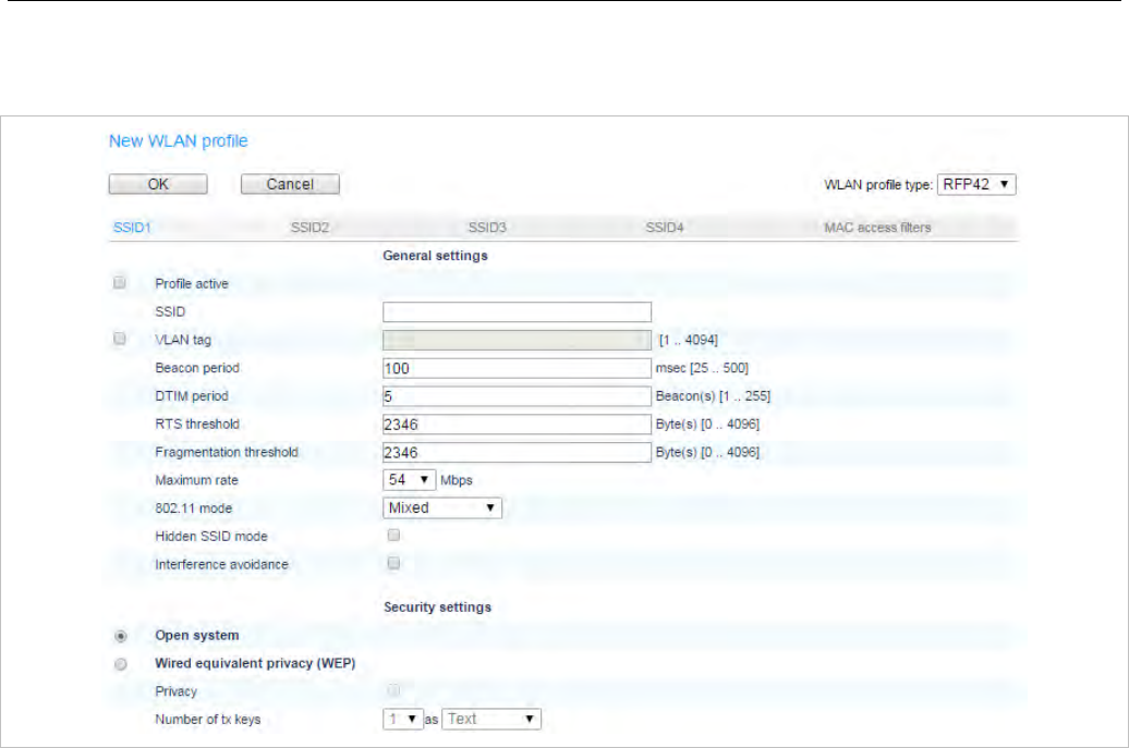
SIP-DECT OM System Manual
100
The New WLAN profile page resp. the WLAN profile [Number] page shows the WLAN profile
configuration.
4 Change the desired settings of the WLAN profile. You need at last to define the ESSID setting. The
different settings are explained in detail in the sections below.
5 Activate the Profile active setting; otherwise the WLAN profile is inactive which de-activates the
WLAN function for base stations that are assigned to this WLAN profile.
6 Press the OK button to apply the settings. If you created a new WLAN profile, you can proceed by
assigning the WLAN profile to the desired base stations (see section 5.6.3). If you changed an
existing WLAN profile, the settings are applied to the assigned base stations automatically.
The following description details the different parameters that are available on the New WLAN profile
page and. on the WLAN profile [Number] page.
General settings
• Profile active: Activate this checkbox to activate the profile. This in turn activates the WLAN function
for all RFPs that are assigned to the WLAN profile.
• SSID: Enter a descriptive character string to identify the WLAN network (e.g. “OurCompany”).The
service set identifier is broadcasted by the RFP within “WLAN beacons” in a regularly interval. The
SSID identifies the WLAN network and is visible by all WLAN clients. This is typically used with a scan
function, e.g. from a WLAN client that tries to establish a connection. The SSID should not exceed 32
characters and it is advisable not to use unusual characters that may trigger WLAN client software
bugs.

OMM Web Service
101
• VLAN tag (number, 1..4094, default: off): You can separate VoIP and client data traffic (transferred
via WLAN) by using different virtual LANs, e.g. to prevent bulk data transfers to interfere with VoIP. To
use a separate VLAN for the client data traffic, activate the check box and enter the desired VLAN
number (see sections 7.18 and 7.12).
• Beacon period (milliseconds, 50..65535, default: 100 ms): Determines the WLAN beacon interval. A
higher value can save some WLAN airtime that can be used for data transfers.
• DTIM period (number, 1..255, default: 5): Determines the number of beacons between DTIM
messages. These messages manage the WLAN wakeup/sleep function e.g. that is critical for battery
powered WLAN clients.
• RTS threshold (bytes, 0..4096, default: 2346): If a WLAN packet exceeds this threshold, it will be
transferred with RTS/CTS handshake. This may improve transfer reliability if several WLANs share
the same channel. The default of 2346 byte switches off this function because the IP-MTU is typically
only 1500 byte.
• Fragmentation threshold (bytes, 0..4096, default: 2346): If a WLAN packet exceeds this threshold, it
will be transferred in chunks. This may improve transfer reliability for a weak connection. The default
of 2346 bytes switches off this function because the IP-MTU is typically only 1500 byte.
• Maximum rate (list of rates in Mbps, 1..54, default: 54): This setting applies to RFP 42 WLAN only.
Determines the maximum transfer rate used by the RFP. You can limit the rate to increase the WLAN
range, e.g. to prevent WLAN clients in the vicinity of the RFP to disturb distant WLAN clients.
• 802.11 mode (RFP 42 WLAN selection list: Mixed / 802.11b only / 802.11g only, default: Mixed): Both
the older and long-ranged B-Mode and the newer and faster G-Mode are typically supported by
WLAN clients. You can change this setting to prevent problems with very old WLAN clients.
(RFP 43 WLAN selection list: 802.11bg /802.11b only / 802.11g only / 802.11abg /802.11n, default:
802.11bg): On the RFP43 profile you can choose additionally 802.11 modes 802.11abg and 802.11n.
Mode 802.11abg 802.11n
Open yes yes
WEP yes no
Radius (802.1x WEP) yes no
WPA v.1 (802.1x + PSK) yes no
WPA v.2 (802.1x + PSK) yes yes
• Hidden SSID mode (on / off, default: off): If switched on, the transmission of the SSID within beacons
is suppressed. This in turn requires a more elaborate and manual connection procedure for WLAN
clients.
• Interference avoidance (on / off, default: off): This setting applies to RFP 42 WLAN only. Enables a
WLAN procedure to enhance radio interference avoidance.
Security settings
These settings determine the encryption used for the WLAN connection. Select one of the four modes
(Open, WEP, WPA, or Radius). This will activate / gray-out the necessary additional input fields that
specify further security settings on the WLAN profile page.

SIP-DECT OM System Manual
102
• Open system: Enable this option to deactivate authentication and encryption (“Hotel mode”). Note,
that all data is transferred un-encrypted in this mode, which can be easily eavesdropped with any
WLAN equipment.
• Wired equivalent privacy (WEP): Enable this option to use the older WEP encryption mode. This
mode may be useful, e.g. if your WLAN should support older WLAN clients that do not implement the
recommended WPA encryption.
- Privacy (on / off, default: off): De-activate this setting to use no authentication (“Open System”)
with standard WEP encryption. Activate this setting to use an additional shared key authentication
between the RFP and the WLAN client.
- Number of tx keys (number, 1..4, default: 1): The WEP encryption can use a single shared key or
multiple shared keys (“key rotation”). Select the number of shared keys, select how to enter a
shared key (by default as Text or as Hex value), and select the Cipher length (see Key settings
below).
- Default tx key (number, 1..4, default: 1): If more than one shared keys is used, you can select the
default shared key. You must configure the same default key on the WLAN client.
- Key #1 – Key #4: Enter one or more shared key. The Cipher length setting (see Key settings
below) determines the length of the required input. If you selected to enter as Text (see above),
input a password with 5, 13, or 29 characters that matches a 64 or 128 bit cipher. If you selected to
enter as Hex value, you can input a hexadecimal number with 10, 26, or 58 characters (0-9, a-f).
Press the Generate button to generate a random shared key that matches the current settings.
• WiFi protected access (WPA): Enable this option to use the recommended WPA encryption mode.
- Type (selection, WPA any / WPA v.1 / WPA v.2, default: WPA any): Select the WPA version
required for WLAN clients. The WPA any setting allows WPA v.1 and WPA v.2 to be used
concurrently. The WPA v.1 setting enforces the use of the older RC4-based encryption. The
WPA v.2 setting enforces the use of the stronger AES encryption. You can also change the
distribution interval (see Key settings below).
- 802.1x (Radius): Select this option if your WLAN should use a RADIUS server for WLAN client
authentication (“Enterprise WPA” with different username/password combinations per client). You
must also specify the Radius settings (see below). For details about the RADIUS authentication
procedure, using the public keys, and importing certificates to the WLAN clients refer to the
documentation of your RADIUS server product.
- Pre-shared key: Select this option to use a single shared key for all WLAN clients (Value setting
below). A WLAN client user needs to enter the shared key in order to connect.
- Value: You can enter a shared key as Text. Use a longer text sequence with alphanumeric
characters and special characters to enhance the shared key strength. A text shared key is case
sensitive. Alternatively, the shared key can be entered as Hex value (hexadecimal number, 0-9, a-
f). Press the Generate button to generate a random shared key that matches the current settings.
• 802.1x (Radius): This setting applies to RFP 42 WLAN only. Enable this option to use the RADIUS
authentication without the stronger WPA encryption. You must also specify the Radius settings and
you may adapt the Key settings (see below).
• MAC access filters (on / off, default: off): This setting applies to RFP 43 WLAN only. You can limit
WLAN access for WLAN clients with specified MAC addresses. Note, that without encryption this
should not be used for security reasons. You can configure a list of MAC addresses that are allowed
to connect via the MAC access filters tab on the WLAN profile page.
• BSS isolation (on / off, default: off): In a standard WLAN setup, each WLAN client can contact other
WLAN clients. For special purposes (e.g. “Internet café setup”), you may switch on this options to
protect WLAN clients from eavesdropping on other WLAN clients.

OMM Web Service
103
Key settings
• Cipher length (selection, 64 Bits / 128 Bits / 256 Bits (RFP 42 WLAN only), default: 64 Bits):
Determines the key length used for the WEP encryption. Larger bit sequences provide better security
but may be unsupported by very old WLAN clients.
• Distribution interval (seconds, 1..65535, default: 20): Determines how often the WEP encryption is
re-negotiated.
Radius settings
The parameters in this section can only be configured if the 802.1x (Radius) option has been selected.
• IP address: Enter the IP address of the RADIUS server.
• Port: Enter the port number used to connect to the RADIUS server. Press the Default button to
change to the standard port.
• Secret: Enter the character string that is used by the RFP to secure the communication with the
RADIUS server.
QoS settings
• WME: (on / off, VLAN or DiffServ (RFP 42 WLAN only), default RFP 42 WLAN: off/VLAN, default
RFP 43 WLAN: off): You can enable the Wireless Media Extensions to prioritize WLAN traffic. The
WLAN traffic priority is determined by VLAN number or by examining the DiffServ data field of IP
packets.
SSID2 – SSID4 Tabs
You can enable up to three additional virtual WLAN networks that are managed by their SSID. This can
be used for example to provide WLAN access for guests that is separated from the company WLAN by
means of VLAN tags and encryption settings. To activate this feature proceed as follows:
1 Switch to the appropriate SSID tab, e.g. SSID2. Activate the Active check box to enable the
additional virtual WLAN. The tab provides separate configuration items for the selected SSID.
2 Enter at least a new SSID. Also enter a currently unused VLAN tag number.
3 You can specify different authentication/encryption settings for each SSID section. For example, you
can use WPA / Pre-shared key with different passwords.
Note that some configuration combinations are incompatible with multiple SSIDs. For example, the
wireless hardware only manages a single WEP encryption key. Also, some features apply to all defined
SSIDs, including the MAC access filters list.
You can edit the MAC access filters list via the MAC access filters tab on the WLAN profile page.
• You can import a prepared list of MAC addresses (*.txt. file, one line per MAC address) Use the
Browse button to select the file from the file system. Afterwards press the Import button.
• To configure single MAC addresses, use the New button in the General settings section. Enter the
address in the following New MAC access filter dialog.
• To delete a single MAC address, click on the icon left behind the address entry. Use the Delete all
button to delete the entire list.
• Using the Save button you can export the MAC address filter list.
The Associate column indicates for each MAC address if the respective WLAN client is currently
connected to the WLAN.

SIP-DECT OM System Manual
104
5.8.1.2 Deleting WLAN Profiles
To delete an existing WLAN profile:
1 You cannot remove WLAN profile that is in use. To remove a currently used WLAN profile, you must
select another WLAN profile for all assigned RFPs first (see section 5.6.3.
2 On the WLAN profiles page click on the icon next to the profile entry.
The Delete WLAN profile? dialog opens showing a summary of the WLAN profile’s configuration.
3 Press the Delete button.
5.8.1.3 Exporting WLAN Profiles
To simplify the configuration of wireless devices, you can export SSID configuration to a XML WLAN
profile file. To export the configuration, click on the icon.
On Windows 7 you can use the “netsh wlan add profile filename=xxx” command to import a WLAN
configuration. Many other tools to import WLAN configuration files are available for Windows Vista /
Windows XP systems (for example wlan.exe from Microsoft).
5.8.2 “WLAN CLIENTS” MENU
The WLAN clients page shows the status of all WLAN clients currently connected to the WLAN. This
can be used for example for troubleshooting purposes. The display shows the total number of connected
WLAN clients and a list of RFPs that are part of the WLAN. For each RFP, the WLAN client connected to
the RFP are listed. You can view the MAC address and the current Status of each WLAN client.
5.9 “SYSTEM FEATURES” MENU
The System features menu allows administration of system features concerning call number handling
and directory access.
5.9.1 “DIGIT TREATMENT” MENU
A number manipulation is provided by the digit treatment feature for corporate directories that handles
both incoming and outgoing calls.
Digit treatment for LDAP directories
A chosen number from an LDAP directory entry is checked against the external prefix pattern and if a
pattern matches, it is replaced by the configured internal prefix pattern. Only the best matching rule will
be applied.
Before a rule is applied, the following characters are automatically removed from the LDAP directory
entry: ‘%’, space, ‘(’ and ‘)’. The result of the conversion is sent to the DECT phone to be displayed e.g.
in the directory entry details and entered in the redial list.
Note: A conversion performed for an LDAP directory entry can be
reversed if the rule is also activated for an outgoing call.
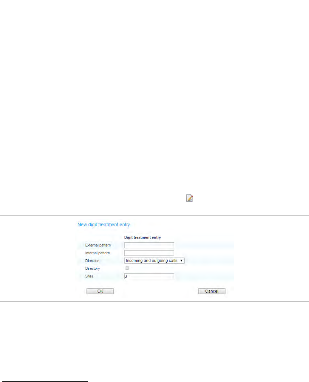
OMM Web Service
105
Incoming call
The calling party number of an incoming call is checked against the configured external prefix pattern
and if a pattern matches it will be replaced by the internal prefix pattern. Only the best matching rule will
be applied.
The result of the conversion is sent to the DECT phone to be displayed and entered in the call log1.
Outgoing call
The dialed number of an outgoing call is checked against the configured internal prefix pattern and if a
pattern matches it will be replaced by the external prefix pattern. This applies to en-bloc dialed numbers
and to overlap sending as long as the SIP session has not been initiated.
Note: To support digit treatment and overlap sending, it is necessary to
have a dial terminator configured.
The result of the conversion is not sent to the DECT phone to be displayed or entered in the call log2.
The following tasks can be performed on the Digit treatment page:
• creating and changing “Digit treatment” entries (see section 5.9.1.1)
• deleting “Digit treatment” entries(see section 5.9.1.2)
5.9.1.1 Creating and Changing “Digit treatment” Entries
1 To configure a new entry, click the New button on the Digit treatment page.
To change the configuration of an existing entry click on the icon left beside the entry.
The New digit treatment entry or the Configure digit treatment entry dialog opens.
2 External pattern: Enter an external prefix pattern with up to 32 characters that matches an incoming
call number or a number received via a directory entry. The prefix to be substituted for calling party
numbers has the same character set as the user telephone number (e.g., :”+*~#,;.-
_!$%&/()=?09aAzZ”).
3 Internal pattern: Enter an internal prefix pattern with up to 32 characters that replaces the external
pattern for the directory entry / incoming calls or vice versa for outgoing calls. An internal prefix
pattern can be composed of characters “*”, ”#” and “0” – “9”.
1 For Incoming Call/Calling Party Number: Depending on the capabilities of the DECT phone and the
level of integration.
2 For Outgoing Call/Called Number: If the user dials the number from the redial list again, the same
procedure will be applied as for the initial dialing.

SIP-DECT OM System Manual
106
Please note: The plus character (“+”) can only be dialed and transferred to a call log with a
Mitel 600 DECT phone.
4 Direction: Select one of the following options:
- “Incoming calls”: Rule applies on incoming calls.
- “Outgoing calls”: Rule applies on outgoing calls.
- “Incoming and outgoing calls”: Rule applies on incoming and outgoing calls.
- “Apply on directory only”: Rule applies to directories only.
5 Directory: This option can be used to specify the rule for incoming and/or outgoing calls. Activate this
option if the rule applies to directories.
6 Sites: Specifies the sites for which a rule is applied e.g. “1, 2” (see section 5.5). If set to “0”, the rule
applies to all sites i.e. the rule will be applied to all calls or corporate directory requests.
7 Press the OK button.
5.9.1.2 Deleting “Digit treatment” Entries
To delete an existing entry:
1 On the Digit treatment page click on the icon left behind the entry.
The Delete digit treatment entry? dialog opens showing the current configuration of this entry.
2 Press the Delete button.
5.9.2 “DIRECTORY” MENU
The Directory menu allows you to manage connections to one or more LDAP or XML servers that in
turn facilitate central corporate directories. The OMM supports multiple LDAP or XML servers with
specific parameter settings to support different types of directories e.g. global corporate directory, group
specific directory, personal directory. XML-based directory services can be implemented using the XML
terminal interface.
If there is more than one directory server configured, multiple options are offered to the user as a list.
The list is presented to the user if the user opens the central directory (e.g., via softkey or by selecting
the central directory from the menu). The user can choose one of the entries in the list. The name of an
entry shown in the list is configured in the OMM when creating the directory server entry. (Latin-1
character set is supported).
• If there is only one directory server configured, the directory function is directly started when pressing
the softkey or selecting central directory from the menu.
• The name configured in the OMM is not relevant and ignored if there is only one directory server
configured.
• There are up to five directory entries configurable.
The OMM determines the display order of the directories in the DECT phone menu by the order
specified by the administrator.
The following tasks can be performed on the Directory page:
• create and change directory entries (see section 5.9.1.1)
• delete directory entries (see section 5.9.2.2)
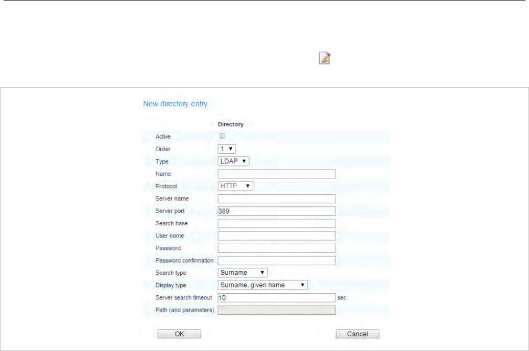
OMM Web Service
107
5.9.2.1 Creating and Changing Directory Entries
1 To configure a new directory entry, click the New button on the Directory page.
To change the configuration of an existing entry click on the icon left behind the entry.
The New directory entry resp. the Configure directory entry dialog opens.
2 In the New directory entry / Configure directory entry dialog enter the parameters for the LDAP
access, see parameter description below.
3 Press the OK button to create or change a directory entry.
The following parameters can be set per directory entry:
• Active flag: allows enabling/disabling of a specific entry.
• Order: determines the position in the DECT phone menu (1 – top; 5 – bottom).
• Type: Select the protocol that is supported by the directory server (LDAP or XML).
• Name: Enter a name for the directory entry. Latin-1 character set is supported.
Note: The name configured here is not relevant and ignored when the
DECT phone user searches for a call number in the telephone’s
central directory if there is only one directory entry configured.
• Protocol: This setting applies only to XML directory entries. Select the preferred transfer protocol.
• Server name (mandatory): Enter the name or IP address of the directory server.
• Server port (mandatory): This setting applies only to LDAP directory entries. Enter the server port
number (default: 389).
Note: SSL (default port 689) is not supported.
Windows® Active Directory Server uses port 3268.
• Search base: This setting applies only to LDAP directory entries. The search base must be edited
(e.g. “ou=people,o=my com”).
• User name, Password, Password confirmation: User name (a distinguished name) and password
may be filled if requested by the directory server. Otherwise an anonymous bind takes place.
Note: SIP-DECT supports LDAP simple bind.

SIP-DECT OM System Manual
108
• Search type: This setting applies only to LDAP directory entries. Searches will be done for one of the
following attributes:
– Name (sn) // Surname (default)
– First name (Given name)
• Display type: This setting applies only to LDAP directory entries. Selection between the following two
alternatives is possible:
– Surname (sn), first name (given name) (default)
– first name (Given name) and Surname (sn)
• Server search timeout: This setting applies only to LDAP directory entries. The search results will be
accepted within the entered search time (value range: 1 - 99 sec).
The configuration is valid for all DECT phones which support the LDAP directory feature. To make
search requests unique for different users the search base configuration can include placeholders
which are replaced by user specific values when submitting the LDAP request to a server. The
following placeholders are defined:
“<TEL>” which is replaced by the specific telephone number of the user
“<DESC1>” which is replaced by the “Description 1” attribute value of the user
“<DESC2>” which is replaced by the “Description 2” attribute value of the user
“SIPProxy” which is replaced by the current primary, secondary or tertiary SIP server address
(SIP-DECT 6.0 and later)
• Path (and parameters): This setting applies only to XML directory entries. Enter the URL (if required
with parameters) where the XML directory is located on the directory server.
Note: The telephone number in SIP-DECT is not limited to numeric
characters.
5.9.2.2 Deleting Directory Entries
1 To delete an existing directory entry click on the icon on the left of the entry on the Directory page.
The Delete directory entry dialog opens showing the current configuration of this entry.
2 Press the Delete button.
5.9.3 “FEATURE ACCESS CODES” MENU
Feature access codes (FAC) allow a DECT phone user to perform specific actions on the OMM from any
subscribed DECT phone.
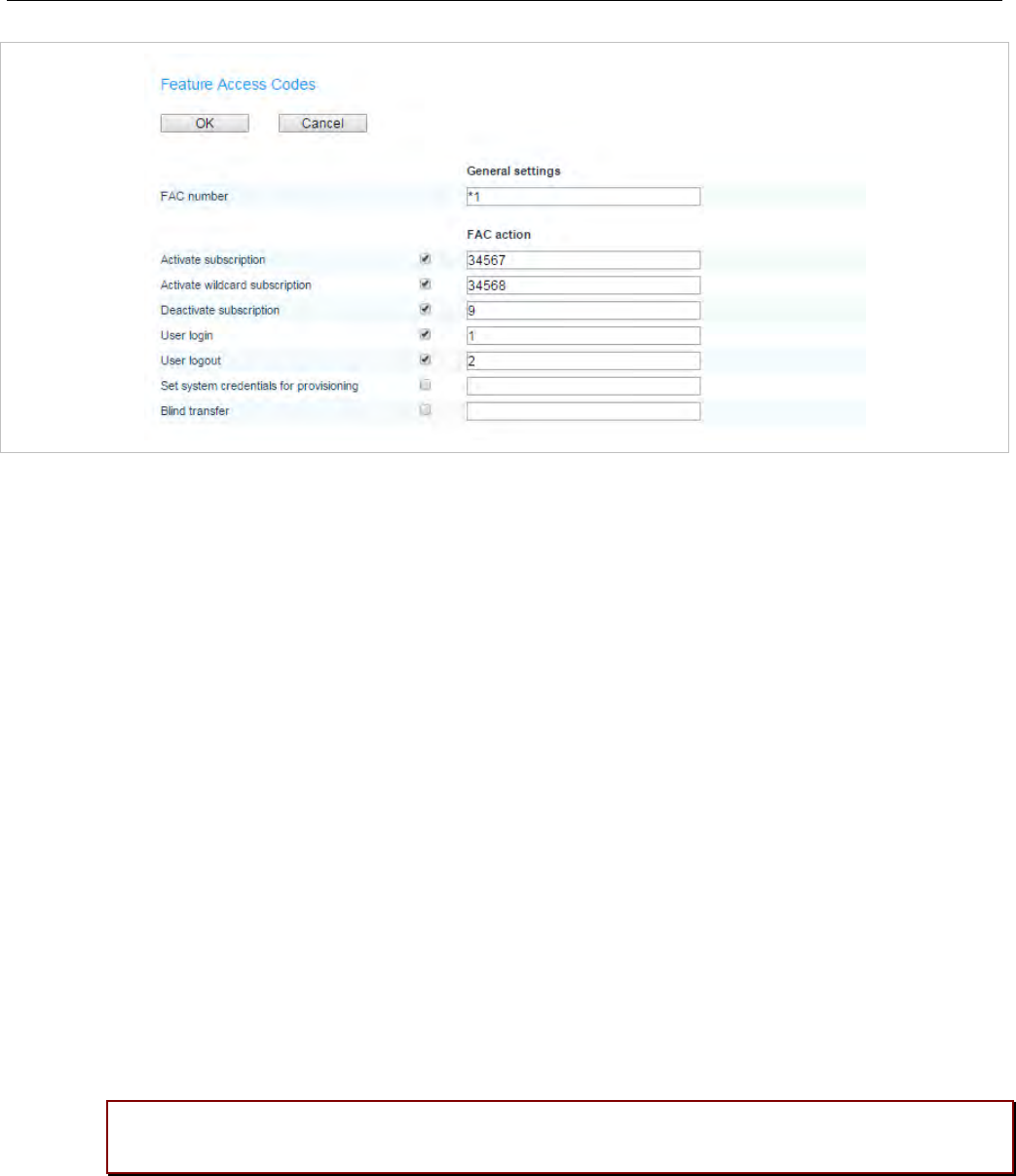
OMM Web Service
109
To configure the FAC feature:
1 FAC number: Enter a unique FAC number.
2 Activate the appropriate checkbox(es) to enable the corresponding FAC feature(s). For each enabled
FAC feature enter an assigned access code.
- Activate subscription: activate subscription of the DECT phone.
- Activate wildcard subscription: activate subscription of the DECT phone (if no IPEI is
configured).
- Deactivate subscription: de-activate DECT phone subscription.
- User login: log the user into the DECT phone.
- User logout: log the user out of the DECT phone.
- Set system credentials for provisioning: allow a user to set system credentials via the Mitel 600
DECT phone.
- Blind transfer: initiate a blind transfer from the DECT phone. When a user dials the “Blind transfer”
FAC en-bloc (in an active call state) followed by a target number, SIP-DECT initiates a blind
transfer to the given target number.
3 Press the OK button.
Afterwards the appropriate action can be performed by dialing the “FAC number” followed by the “FAC
access code” en-bloc from any subscribed DECT phone.
In the example above a subscribed user can activate the OMM DECT subscription by dialing “*134567”
en-bloc.
Please note: Overlap sending is not supported for FAC. “FAC number” and “FAC action
code” must be entered en-bloc.
FAC functions will be confirmed by an audible indication to the user (in-band tone signals).
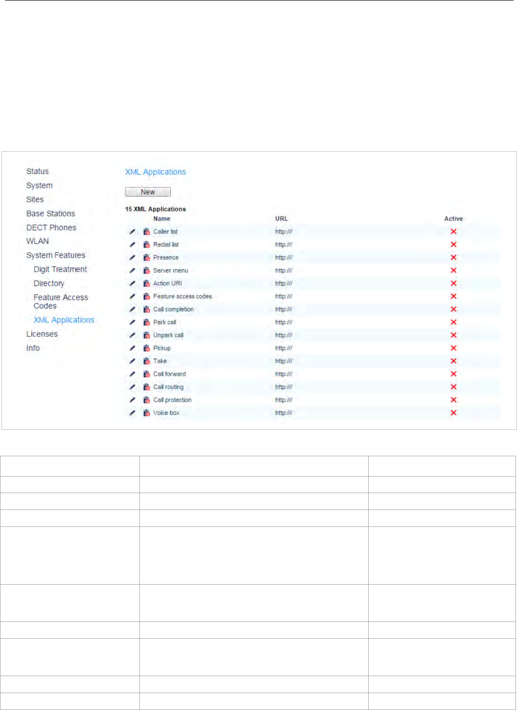
SIP-DECT OM System Manual
110
5.9.4 ”XML APPLICATIONS” MENU
The SIP-DECT XML terminal interface allows external applications to provide content for the user on the
Mitel 600 DECT phone display. To make the XML terminal interface applications available for the DECT
phone user, you must configure the appropriate hooks in the XML Applications menu.
When the application hook is enabled in the OMM, Mitel 600 DECT phone users can program a softkey
with the specific hook (or select the relevant menu option) to trigger the associated action. The side keys
on the Mitel 600 DECT phones only display icons in idle state. In an active call state only the two
softkeys below the display indicate the active feature.
The following table summarizes the predefined XML application hooks:
Hook Description DECT Phone menu
Caller list Hook to replace the local caller list. >>> > Info > Caller List
Redial list Hook to replace the local redial list. >>> > Info > Redial List
Presence Hook to reach a presence application . >>> > Presence
Server menu Hook to reach a server menu. The OMM system menu
is available as a menu entry in the local main menu of
the DECT phone (>>> softkey). If no user is assigned
to the DECT phone, the server menu is the only
available XML application hook.
>>> > Info > Server
Action URI URI to be called in case of user/device events. The
URI is configured in the OMM via OMP. Content can
be pushed towards the DECT phone via SIP notify.
n/a
Feature access codes Hook to provide Feature Access Codes translation.
Call completion Hook to provide callback option when a user places an
outgoing call and wants to request a callback before
releasing the call.
>>> > Info > Calback
Park call Hook to the Park Call service interface. >>> > Call option > Park call
Unpark call Hook to the Unpark Call service interface. >>> > Unpark call

OMM Web Service
111
Pickup Hook to the Pickup Call service interface. >>> > Pickup
Take Hook to Take Call service interface. >>> > Take
Call forward Hook to the Call Forward service interface. >>> > Call forward
Call routing
(Mitel 602 DECT phones only) Hook to the Personal Call Routing service interface. >>> > Call routing
Call protection
(Mitel 602 DECT phones only) Hook to the PBX call protection service interface. >>> > Call protection
Voice box Hook to Voice Mail service interface. >>> > Info > Voice box
These hooks can be activated or deactivated but not deleted. You can create up to 10 additional hooks
dynamically.
Note: The “Call forward” XML hook replaces the “Call forwarding /
diversion” supplementary service. When activated, the “Call
forwarding / diversion” supplementary service is automatically
deactivated and all user specific settings are removed.
For more information on creating, activating or deleting XML hooks, see section 6.12.6.
5.10 “LICENSES” MENU
The Licenses page provides an overview on the currently used license. On this page you can also
import an activation or license file:
1 Select the path and file name where the activation or license key is stored.
2 Click the Import button.
For a detailed description on the OMM licensing model see section 4.
5.11 “INFO” MENU
The Info page displays the End User License Agreement (EULA).
With the first login to a new SIP-DECT software version, this page is displayed automatically and the
user must accept the EULA by clicking the Accept button.
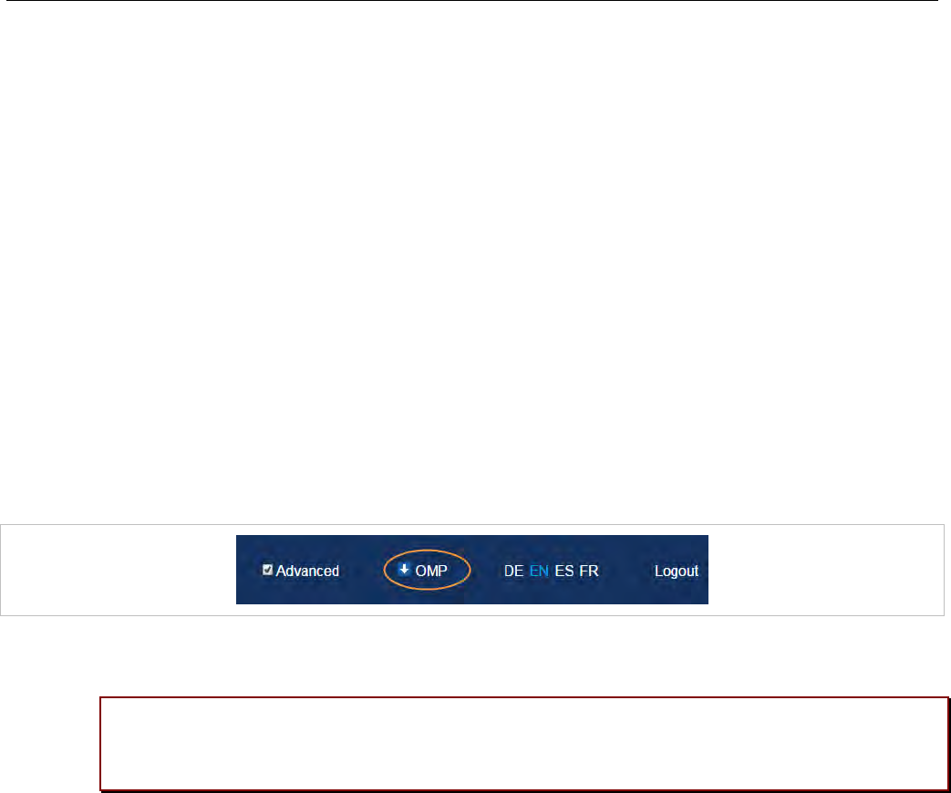
SIP-DECT OM System Manual
112
6 OM MANAGEMENT PORTAL (OMP)
The OM Management Portal (OMP) is a Java tool used to manage the SIP-DECT solution. It can be
used to view and configure OMM system data and has integrated monitoring and other maintenance
features.
SIP-DECT supports Java web start to start the OMP. Java 1.7 is required to run OMP 5.0 or later. By
default, the source for the OMP binary is a Mitel web server (RFP-OMM) or the OMP.jar from the RPM
installation (PC-OMM).
You can also configure a different source (System settings -> OMP web start in the OMM Web service,
or System -> Advanced settings -> Additional services – OMP web start in the OMP). The following
configuration order is used:
• GUI-configured OMP web start URL in RFP-OMM installations
• Environment variable ‘OM_WebStartUrl’ (e.g. set by ipdect.cfg configuration file)
• Mitel web server (RFP-OMM) / from RPM installation (PC-OMM)
You can download the OMP jar file from the OMM Web service by clicking on the OMP link in the top
bar:
Double-click on the downloaded file (OMP.jnlp) and click “Run” in the dialog window. The OM
Management Portal starts and prompts for login credentials.
Please note: Configuration of a non-default source must not contain login credentials
because this is not supported by the Java Web Start mechanism. The HTTP/FTP server
must be configured accordingly.
This section lists all parameters which can be configured and viewed using OMP. All parameters which
are also accessible by the OM Web service are described in the appropriate OM Web service section
(section 5). New parameters which are only accessible via OMP are described in this section.
6.1 LOGIN
The OMM allows more than one user at a time to configure the system.
To log in to the system enter the following data:
• IP address of the OMM.
• User name, Password: Enter a user name and a password. Both strings are checked case sensitive.
With initial installation or after removing the configuration file, the OMM Web service is accessible via
a default built-in user account with user “omm” and password “omm”.
The System name is set by the system administrator after first successful login to the OMM, see section
6.5.1.
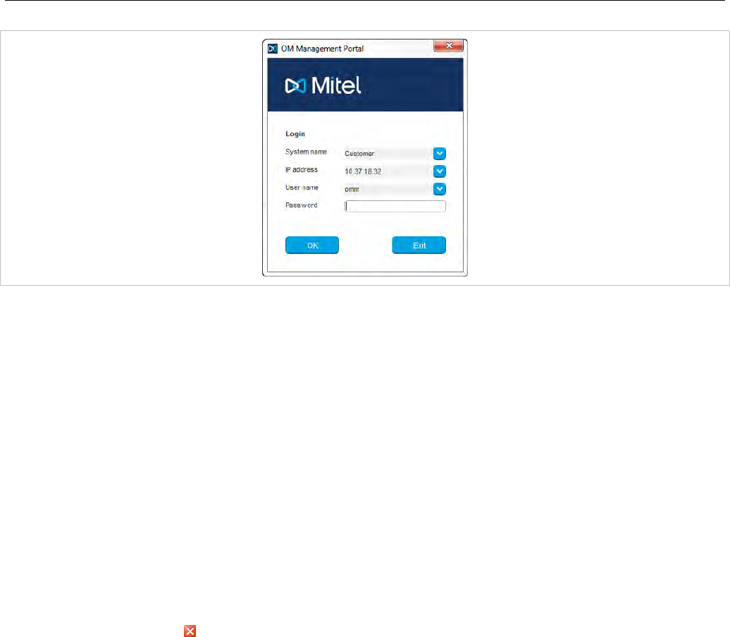
OM Management Portal (OMP)
113
The system name and the IP address of successful logins are stored in the local OMP preferences and
can be reselected for further logins. Up to 10 different login datasets can be stored.
• On a Linux system, preferences are stored in the user’s home directory “~/.java/.userPrefs/…”.
• On a Windows system, preferences are stored in the registry node
“HKEY_CURRENT_USER/Software/JavaSoft/Prefs/…”.
After login the OMP is set to the configuration mode page showing the system status page which
contains health state information of the connected OMM (see section 6.4). If there is a version difference
between the OMP and the OMM, this will also be indicated here. Details can be viewed in the Help:
About AXI menu (see section 6.15).
6.2 LOGOUT
There is no automatic logout for the OMP. The user must log out manually.
To log out from the system:
• click on the Close icon in the upper right corner of the OMP window
• select the Exit entry from the General drop-down menu.
Note: If the OMM link is broken, the OMP asks if you want to reconnect
to the OMM. In that case, you must enter the login data again.
6.3 OMP MAIN WINDOW
The header of the OMP window shows the version of the connected OMM.
“OMP mode” toolbar buttons
The OMP provides different modes: configuration mode, monitor mode and planning mode.
Configuration mode allows changing of parameters. In monitor mode, parameters are only displayed, but
are not changeable. Monitor mode provides additional features, e.g. system and RFP statistics and RFP
synchronization monitoring. Planning mode enables the creation of graphics which can be used with the
OM Locating application to visualize the placement of the RFPs (see also /27/).
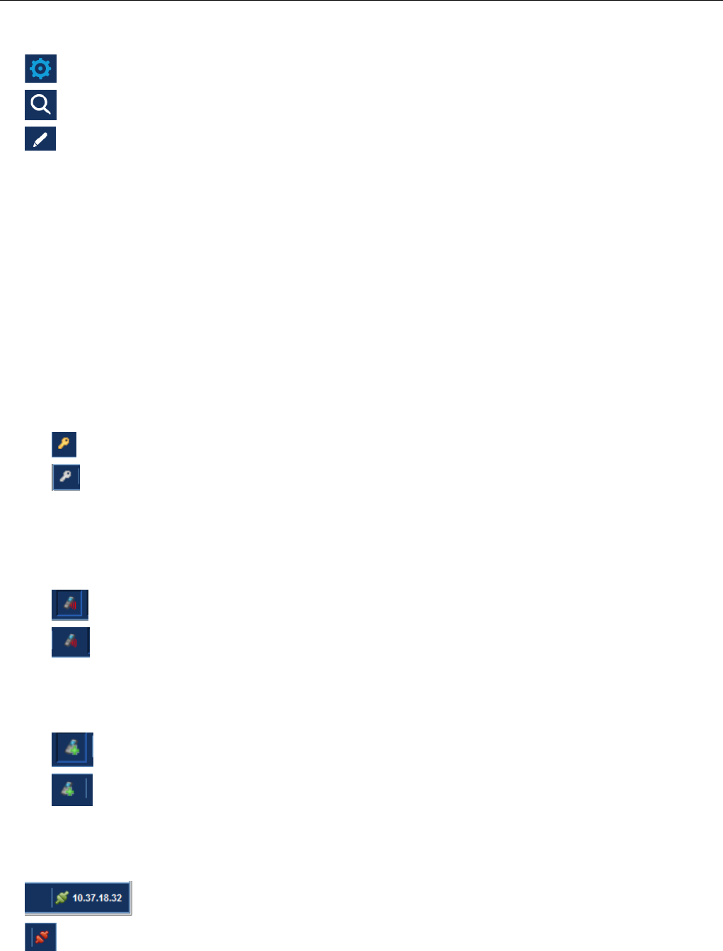
SIP-DECT OM System Manual
114
To select the desired mode, press the appropriate button in the upper toolbar of the OMP window:
• Configuration mode
• Monitor mode
• Planning mode
Main menus
The OMP provides two main menus which are available in all program situations:
• General menu, see section 6.14.
• Help menu, see section 6.15.
Navigation panel
Both configuration and monitor mode contain a navigation panel. This panel contains the mode-
dependant menu.
Status bar
The status bar is located at the bottom of the main window. It shows the following items:
• Encryption state:
The icon indicates that encryption is enabled.
The icon indicates that encryption is disabled.
This setting can be configured in the DECT tab of the System settings menu (see also section
6.5.1).
• PARK,
• Subscription state: Clicking on one of the following icons enables / disables subscription.
The icon indicates that subscription is enabled.
The icon indicates that subscription is disabled.
Subscription can also be enabled / disabled in the DECT phones menu (see also section 6.7.8).
• Auto-create on subscription state: Clicking on one of the following icons enables / disables Auto-
create on subscription.
The icon indicates that Auto-create on subscription is enabled.
The icon indicates that Auto-create on subscription is disabled.
This setting can also be configured in the DECT tab of the System settings menu (see also section
6.5.1).
• Connection status to the OMM:
If connected to the OMM, the IP address of the OMM is displayed.
OMP is disconnected from the OMM.
Info console
General OMP events are displayed the Info console.
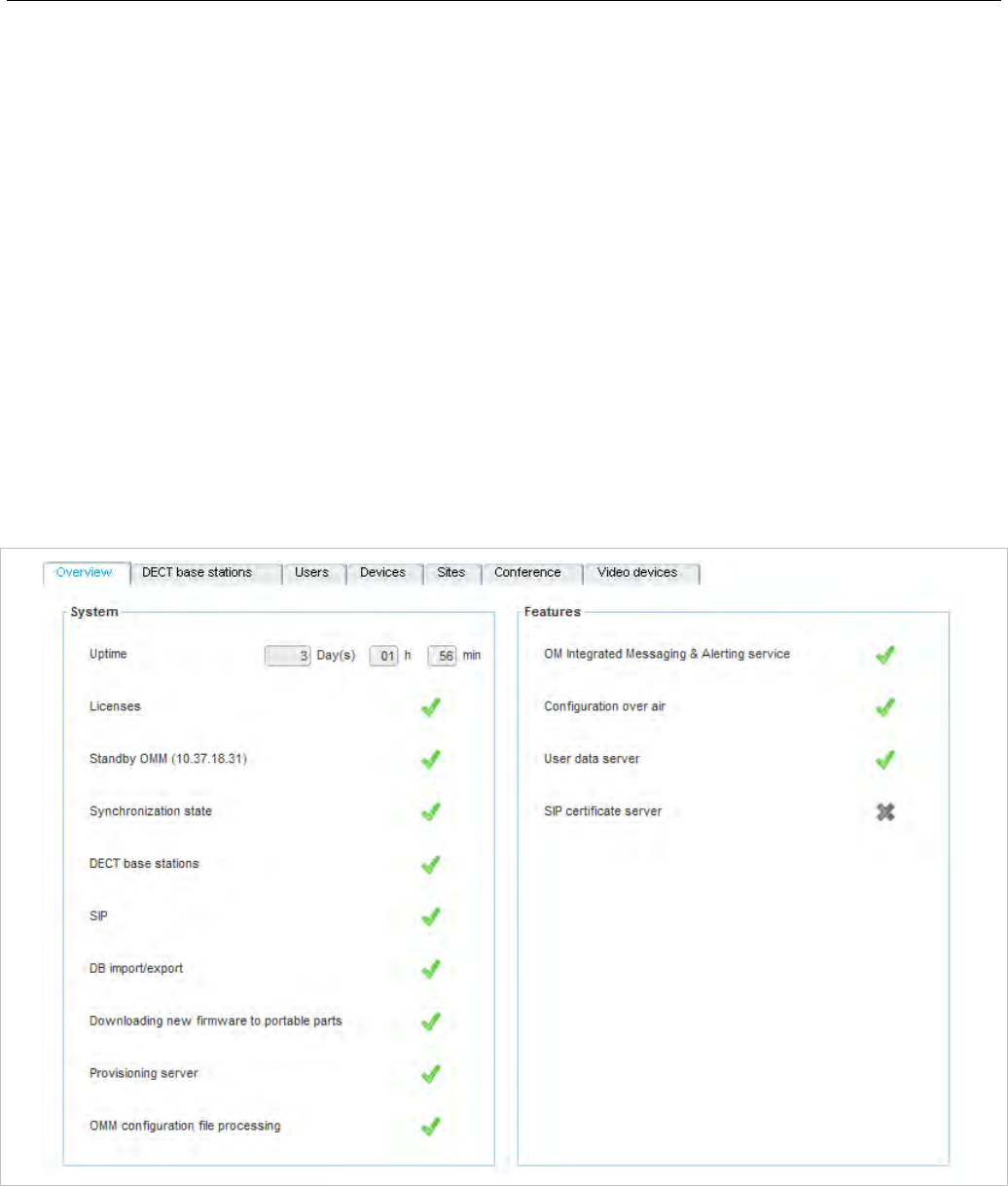
OM Management Portal (OMP)
115
6.4 “STATUS” MENU
The system status is displayed after startup of OMP. The Status panel provides information about the
system health states, and contains the following tabs:
• Overview (see section 6.4.1)
• DECT base stations (see section 6.4.2)
• Users (see section 6.4.3)
• Devices (see section 6.4.4)
• Sites (see section 6.4.5)
• Conference (see section 6.4.6)
• Video devices (see section 6.4.7)
6.4.1 OVERVIEW
The “Overview” tab consists of a “System” panel providing general system health states information and
a “Features” panel which shows health states of system features. Some of these features are optional;
that means the relevant health state is only shown if the feature is activated in system.

SIP-DECT OM System Manual
116
The “Overview” tab shows following system information:
• System uptime: Elapsed time since OMM start (in days, hours and minutes)
• Licenses: Licenses health state
• Standby OMM: Standby OMM IP address and health state of standby configuration (if no standby
OMM is configured a grey cross is shown)
• Synchronization state: Synchronization health state
• DECT base stations: Base stations health state
• SIP: SIP health state
• DB import/export: DB import/export health state
• Downloading new firmware to portable parts: (Health) state of firmware download to DECT
phones
• Provisioning server: Health state of provisioning server health state
• OMM configuration file processing: Health state of configuration file processing.
Depending on OMM system configuration, the “Features” tab consists of all or a subset of these health
states:
• OM Integrated Messaging & Alerting service: Messaging and alerting feature health state (always
active)
• SIP certificate server: SIP certificate server health state (always active)
• Configuration over Air: Central DECT phone configuration over air state (optional)
• User data server: User data server health state (optional)
• User monitoring: User monitoring health state (optional)
• Video: Video health state (optional)
Health states can have the following values:
• – inactive or unknown
• – error
• – OK
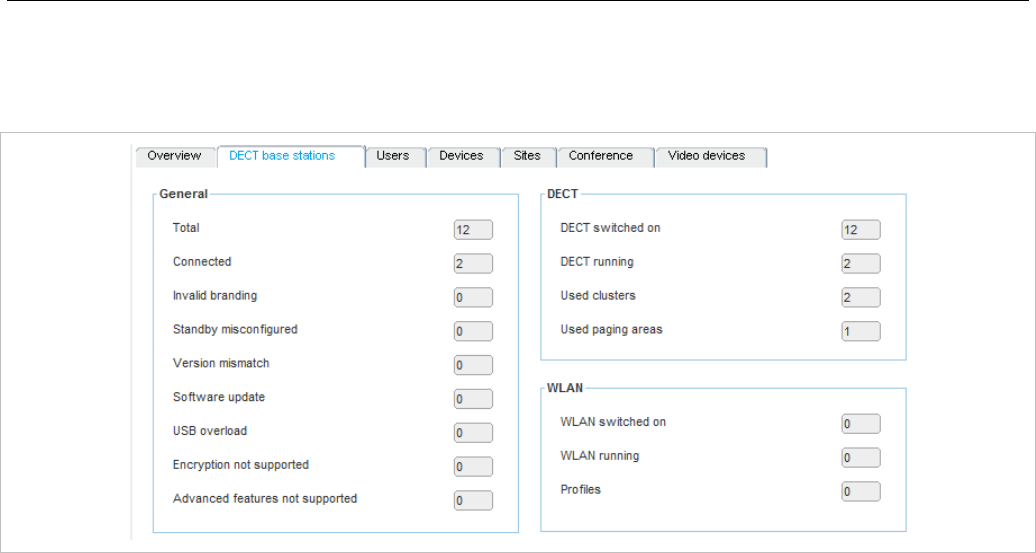
OM Management Portal (OMP)
117
6.4.2 DECT BASE STATIONS
The “DECT base stations” tab contains the following sections: “General”, “DECT” and “WLAN”.
The “General” panel provides counters related to RFP configuration and state:
• Total: Total number of RFPs configured
• Connected: Number of RFPs connected to OMM
• Invalid branding: Number of connected RFPs with invalid branding
• Standby misconfigured: Number of connected RFPs with wrong standby configuration
• Version mismatch: Number of connected RFPs running with wrong software version
• Software update: Number of connected RFPs requesting software update
• USB overload: Number of connected RFPs detecting overload at their USB port
• Encryption not supported: Number of connected RFPs not supporting encryption
• Advanced features not supported: Number of connected RFPs not supporting “Advanced features”
which covers “Hi-Q audio technology”, “Terminal video”, “Enhanced DECT security” and “SRTP”.
The “DECT” panel provides counters related to RFPs DECT configuration and state:
• DECT switched on: Number of configured RFPs with DECT switched on
• DECT running: Number of connected RFPs with DECT running
• Used cluster: Number of configured clusters
• Used paging areas: Number of paging areas used by RFPs
The “WLAN” panel provides counters related to RFPs WLAN configuration and state:
• WLAN switched on: Number of configured RFPs with WLAN switched on
• WLAN running: Number of connected RFPs with WLAN running
• Profiles: Number of WLAN profiles used by RFPs
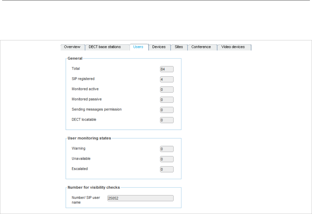
SIP-DECT OM System Manual
118
6.4.3 USERS
The “Users” tab provides information about DECT phone users.
The “General” panel provides counters concerning DECT phones user configuration and states:
• Total: Total number of configured users
• SIP registered: Number of configured users registered at SIP server
• Monitored active: Number of configured users with active monitoring enabled
• Monitored passive: Number of configured users with passive monitoring enabled
• Sending messages permission: Number of configured users with message sending permission
enabled
• DECT locatable: Number of configured users with DECT locatable enabled
The “User monitoring states” panel provides counters concerning DECT phone user monitoring state
• Warning: Number of monitored users in state ‘Warning’
• Unavailable: Number of monitored users in state ‘Unavailable’
• Escalated: Number of monitored users in state ‘Escalated’
The “Number for visibility checks” panel provides phone number or SIP user name used for standby
OMM visibility checks.
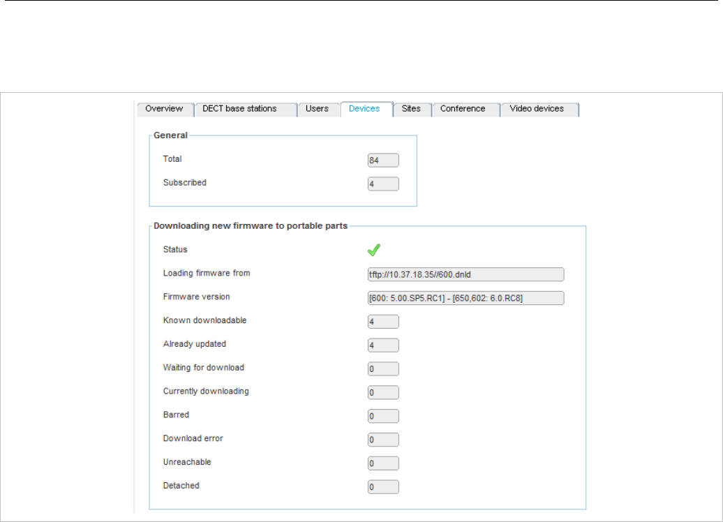
OM Management Portal (OMP)
119
6.4.4 DEVICES
The “Devices” tab provides information about DECT phones.
The “General” panel contains counters related to DECT phones:
• Total: Total number of configured DECT phones
• Subscribed: Number of configured DECT phones which are subscribed to OMM
The “Downloading new firmware to portable parts” panel provides information about state of DECT
phone firmware download:
• Status: Status of firmware download
• Loading firmware from: URL of firmware download container
• Firmware version: Version info of firmware container
• Known downloadable: Number of DECT phones known as downloadable
• Already updated: Number of DECT phones already updated
• Waiting for download: Number of DECT phones waiting for download
• Currently downloading: Number of DECT phones currently downloading
• Barred: Number of downloadable DECT phones currently barred
• Download error: Number of downloadable DECT phones with download error
• Unreachable: Number of downloadable DECT phones currently unreachable
• Detached: Number downloadable DECT phones currently detached
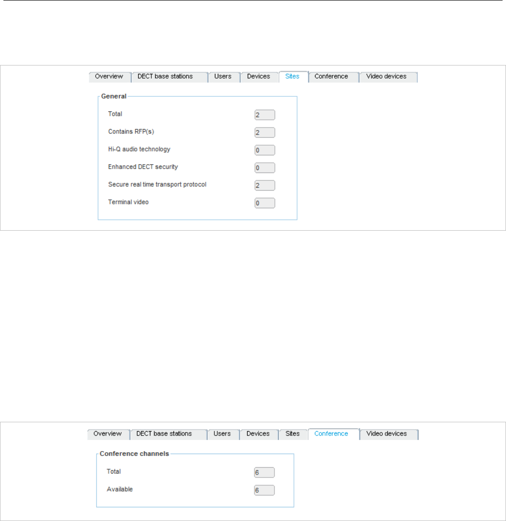
SIP-DECT OM System Manual
120
6.4.5 SITES
The “Sites” tab provides counters concerning site configuration and state:
• Total: Total number of configured sites
• Contains RFPs: Number of sites with dedicated RFPs
• Hi-Q audio technology: Number of sites with Hi-Q audio technology enabled
• Enhanced DECT security: Number of sites with “Enhanced DECT security” enabled
• Secure real time transport protocol: Number of sites with “Secure real time transport protocol”
(SRTP) enabled
• Terminal video: Number of sites with terminal video enabled
6.4.6 CONFERENCE
The “Conference” tab provides conference channel information:
• Total: Total number of conference channels in system
• Available: Number of currently available conference channels
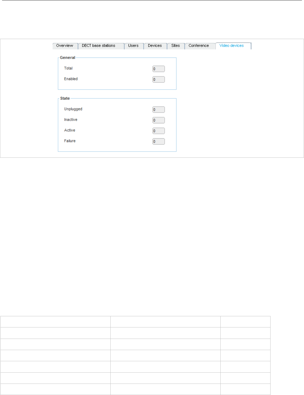
OM Management Portal (OMP)
121
6.4.7 VIDEO DEVICES
The “Video devices” tab provides video device state information.
The “General” panel provides video device configuration related counters:
• Total: Total number of configured video devices
• Checkpoint: Number of video devices enabled
The “State” panel provides video device state related counters:
• Unplugged: Number of video devices in state unplugged
• Inactive: Number of video devices in state inactive
• Active: Number of video devices in state active
• Failure: Number of video devices in state failure
6.5 “SYSTEM” MENU
The System menu allows configuration and display of global OMM settings. The system settings are
changeable in configuration mode. Change of some parameters can cause the OMM to be reset. In this
case a new login is required.
The System menu provides the following entries:
Configuration mode Monitor mode See section
Basic settings Basic settings 6.5.1
Advanced settings Advanced settings 6.5.2
Statistics 6.5.3
SIP SIP 6.5.4
User administration User administration 6.5.6
Data management Data management 6.5.7
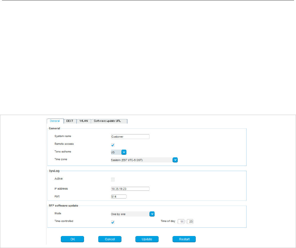
SIP-DECT OM System Manual
122
6.5.1 “BASIC SETTINGS” MENU
The Basic settings menu contains general settings for the OpenMobility Manager and contains the
following tabs:
• General (see section 6.5.1.1)
• DECT (see section 6.5.1.2)
• WLAN (see section 6.5.1.3)
• Software update URL (only on systems where the OMM is running on a DECT base station) (see
section 6.5.1.4)
6.5.1.1 General settings
The following parameters can be set on the General tab of the “Basic Settings” menu.
General
• System name: Name of the SIP-DECT system.
• Remote access: Enables or disables SSH access to all RFPs in the DECT system. For more
information on SSH access, see section 8.3.5.
• Tone scheme: Specifies the country in which the OMM resides, which enables country-specific tones
(e.g., busy tone, dial tone, etc).
• Time zone: Specifies the time zone in which the OMM is operating.
Syslog
• Active: Enables propagation of syslog messages by the OMM and RFPs.
• IP address: Address of the host that collects the syslog messages.
• Port: Port of the host that collects the syslog messages.
• Forward OMM Messages to syslog: (Visible only on a PC-hosted OMM system) Enables/disables
forwarding of syslog messages from the PC-hosted OMM.
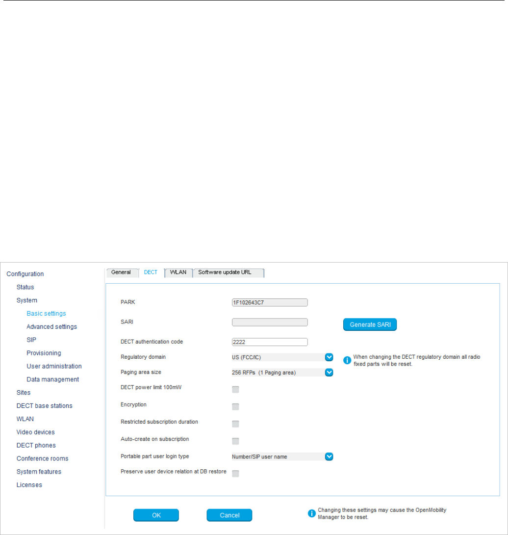
OM Management Portal (OMP)
123
RFP software update
• Mode: RFP update mode. Options are “One by one” (each RFP is updated separately) or “All at once”
(all RFPs are updated in one operation).
• Time-controlled: Indicates whether the start of the RFP update is time-controlled.
• Time of day: Specifies the time for time-controlled RFP updates.
Note: Updates triggers can be controlled through update intervals
(DHCP, config files) or manually triggered via the Update button.
The “General” tab contains two additional buttons (aside from default buttons):
• Update: Requests an immediate update of RFP software.
• Restart: Requests an OMM restart.
6.5.1.2 DECT settings
For a description of the parameters which can be set in the DECT tab, see the description of the System
settings page of the OMM Web service (see section 5.4.1). The corresponding parameters are
described in the DECT settings and Downloading new firmware to portable parts page sections, with
the exceptions noted below.
The following settings are only available in the OMP.
• Regulatory domain: the OMP offers an additional regulatory domain selection
(Radio 1910-1927MHz 250mW) for SIP-DECT operation in some South American countries. See
section 3.32 for more information on this feature.
• SARI: Specify the Secondary Access Rights Identifier (SARI) for the Dual Homing feature. DECT
phones subscribe to the SARI (instead of the PARK) to ensure that user data is synchronized across
all OMMs in the system. See section 7.16 for more information on this feature. You can click the
Generate SARI button to generate the SARI from the system PARK code.

SIP-DECT OM System Manual
124
• Paging area size: Select the number of paging areas for the SIP-DECT system. A paging area can
consist of up to 256 RFPs (and the smallest group can consist of 16 RFPs). The configuration of the
paging areas is done in the Paging areas menu of the OMP (see section 6.7.2).
• Restricted subscription duration: Restricts the time period throughout which a DECT phone can be
subscribed to 2 minutes. Furthermore, the subscription mode will be disabled immediately after every
successful subscription of a DECT phone.
• Auto-create on subscription: Activate this option if an unbound subscription of DECT phones
should be allowed. See the OM DECT Phone Sharing and Provisioning Guide for more information.
6.5.1.3 WLAN settings
For a description of the parameters which can be set in the WLAN tab, see the description of the
System settings page of the OMM Web service. The same parameters are described in the WLAN
settings section (section 5.4.1.3).
6.5.1.4 Software Update URL settings
With SIP-DECT 6.0 or later, DECT base stations in small SIP-DECT systems (~10 RFPs) can obtain
their software image from the RFP OMM, if they have no valid URL from which to load their software. If
the OMM is running on a RFP, the RFP OMM delivers the software to the connected RFPs.
You configure the URL for the RFP software image (iprfp3G.dnld ) on this tab. This tab is only available
when the OMM resides on an RFP.
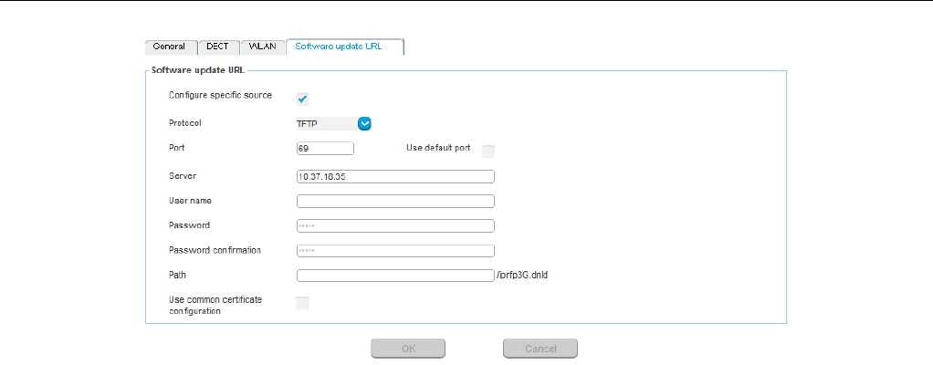
OM Management Portal (OMP)
125
For a description of the parameters that can be set in the Software update URL tab, see the description
of the System settings page of the OMM Web service. The same parameters are described in the
Software update URL section (section 5.4.1.10).
6.5.2 “ADVANCED SETTINGS” MENU
The Advanced settings menu contains additional settings for the OpenMobility Manager, and contains
the following tabs:
• Net parameters (see section 6.5.2.1)
• DECT phones (see section 6.5.2.2)
• DECT phone firmware (see section 6.5.2.3)
• IMA (see section 6.5.2.4)
• Additional services (see section 6.5.2.5)
• User monitoring (see section 6.5.2.6)
• Special branding (see section 6.5.2.7)
• Core dump (see section 6.5.2.8)
• Remote system dump (see section 6.5.2.9)
• OMM certificate (see section 6.5.2.10)
• OMM certificate server (see section 6.5.2.11)
• SNMP (see section 6.5.2.12)
• Time zones (see section 6.5.2.13)
6.5.2.1 Net parameters
For a description of the parameters that can be set in the Net parameters tab, see the description of the
System settings page of the OMM Web service. The same parameters are described in the Net
Parameters section (section 5.4.1.13).
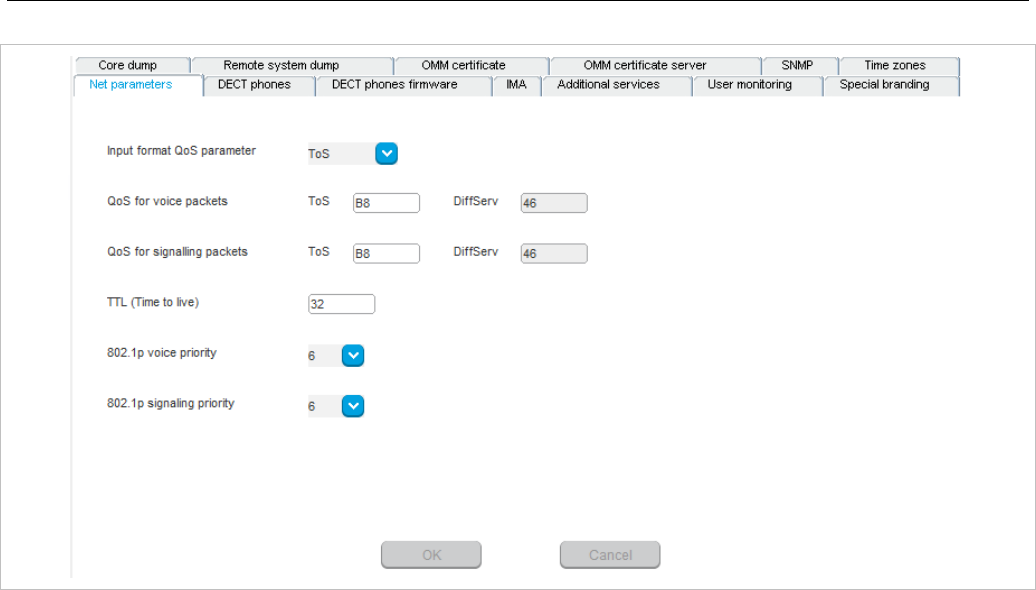
SIP-DECT OM System Manual
126
• Input format QoS parameter: format for quality of service parameter. Available options are ToS or
DiffServ.
• QoS for voice packets: Specifies the value of the type of service (ToS ) or DiffServ byte (depending
on the QoS input format value) of the IP packet header for all packets that transport RTP voice
streams.
• QoS for signalling packets: Specifies the value of the type of service (ToS ) or DiffServ byte
(depending on the QoS input format value) of the IP packet header for all packets related to VoIP
signaling.
• TTL (Time to live): Specifies the maximum hop count for all IP packets.
• 802.1p voice priority: Specifies the VLAN priority tag for RTP packets.
• 802.1p signaling priority: Specifies the VLAN priority tag for VoIP signaling packets.
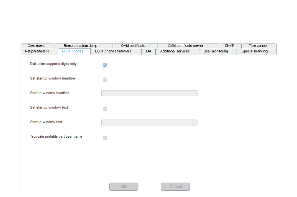
OM Management Portal (OMP)
127
6.5.2.2 DECT Phones
The OMM can set certain start-up text settings on the DECT Phone over the air. For more information on
this feature see section 3.22.
• Dial editor supports digits only: enables a digits-only mode for the DECT phone dial editor. In this
mode, the ”*” has the meaning of a digit to be dialed, even if short-pressed. If the mode is not
enabled, a short press of the ”*” key changes the editor mode to alphanumric.
• Set startup window headline: Enables display of the text string specified in the Startup window
headline field.
• Startup window headline: text headine to be displayed in the DECT phone window at startup.
Default value is ”my company”.
• Set startup window text: Enables display of the text string specified in the Startup window text
field.
• Startup window text: text string to be displayed in the DECT phone window at start. Empty by
default.
• Truncate portable part user name: Enables or disables truncating the name of the user registered
to the DECT phone.
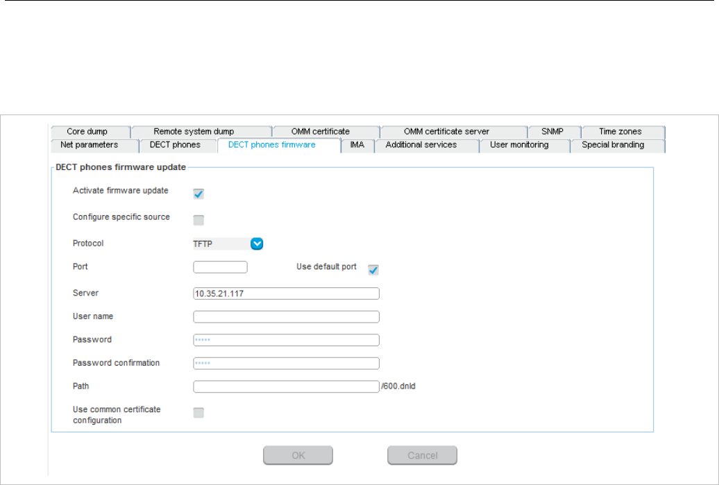
SIP-DECT OM System Manual
128
6.5.2.3 DECT phones firmware
The OMM can provide a DECT phone firmware update over the air. If the Activate firmware update
checkbox is enabled, the “Download over Air” feature is activated. For more information on this feature
see section 7.22.
For a description of the parameters on the DECT Phone firmware tab, see section 5.4.1.6.
6.5.2.4 IMA
The Integrated Message and Alarm (IMA) configuration is stored in the OMM database. You can
configure a specific URL for the OMM to retrieve the IMA configuration file (ima.cfg). The IMA
configuration remains available even if the configured server becomes unavailable.
When you set a specific URL, the OMM uses that URL to load the IMA configuration file during startup. If
no specific IMA configuration file source is configured, the provisioning server settings (ConfigURL) are
used to retrieve the ‘ima.cfg’ file.
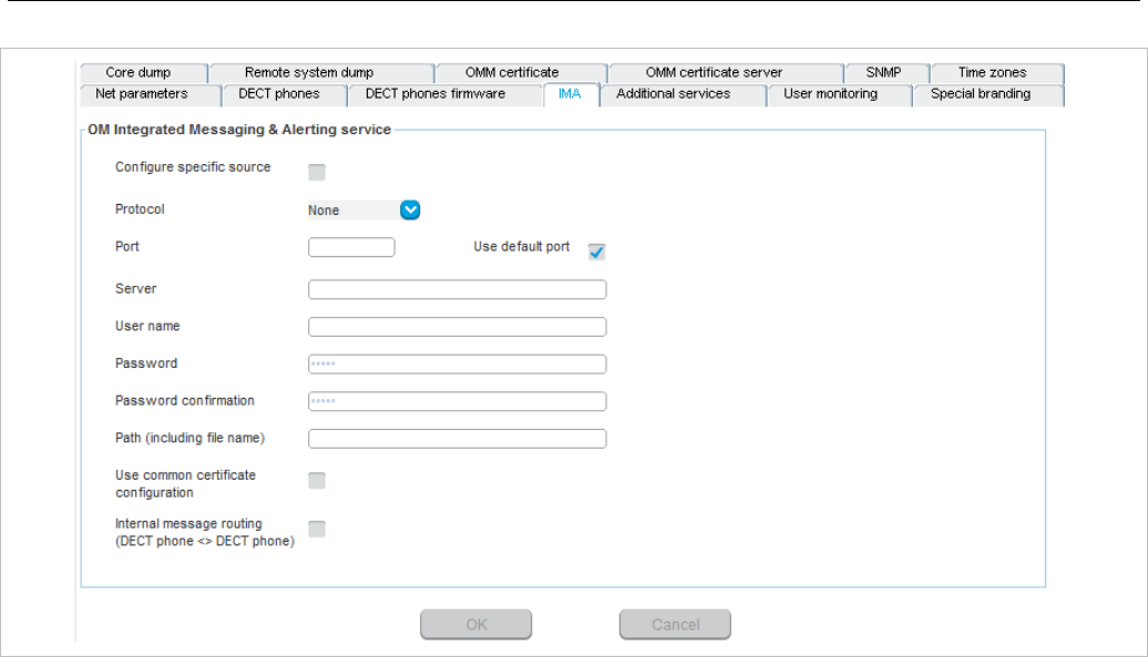
OM Management Portal (OMP)
129
For a description of the parameters on the IMA tab, see the description of the System settings page of
the OMM Web service. The same parameters are described in the OM Integrated Messaging &
Alerting service section (section 5.4.1.8).
6.5.2.5 Additional services
For a description of the parameters on the Additional services tab, see the description of the System
settings page of the OMM Web service. The same parameters are described in the following sections:
• Voice mail (section 5.4.1.7)
• OMP web start (section 5.4.1.5)
• Date and time (for NTP servers) (section 5.4.1.14)
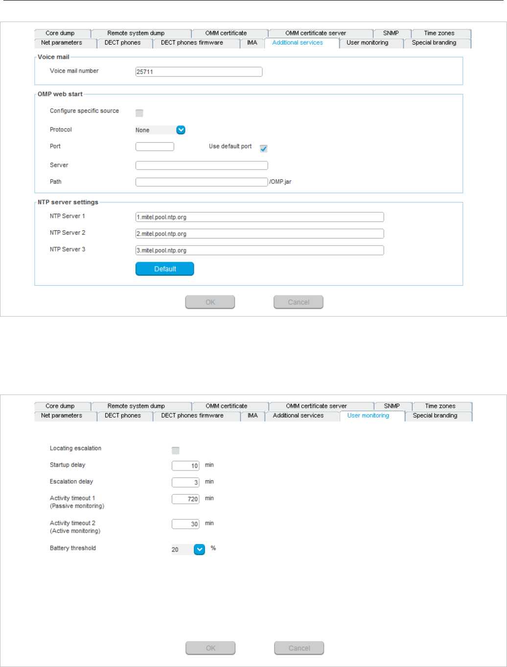
SIP-DECT OM System Manual
130
6.5.2.6 User monitoring
The User monitoring tab allows you to configure the system-wide parameters for the user monitoring
feature.
• Locating escalation: If this option enabled, the alarm trigger “LOC-ERR-USERSTATE” will be
generated by the OMM. Default setting is “off”.
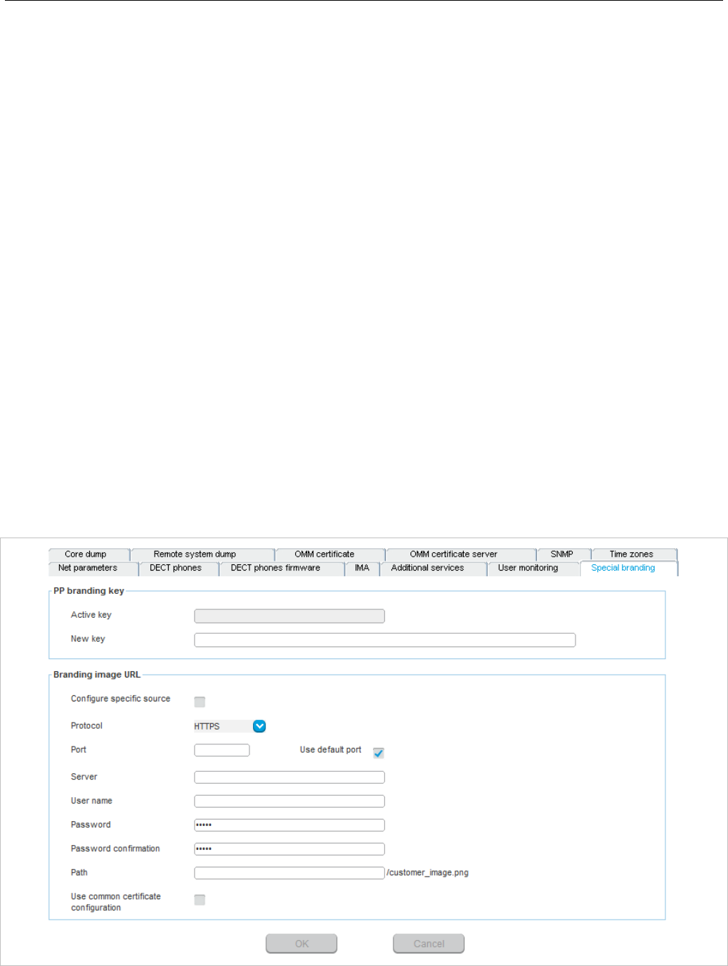
OM Management Portal (OMP)
131
• Start-up delay: The start-up delay defines the period of time the user monitoring start-up is delayed
(between 2 and 15 minutes) after failover or system start-up.
• Escalation delay: The escalation delay defines the period of time the user monitoring will wait before
the unavailable status is escalated.
• Activity timeout 1: The activity timeout 1 defines the maximum time (between 30 and 1440 minutes)
between user activities in passive monitoring mode.
• Activity timeout 2: The activity timeout 2 defines the maximum time (between 5 and 60 minutes)
between user activities in active monitoring mode.
• Battery threshold: The battery threshold defines the minimum battery load (between 0 and 100% in
steps of 5%).
6.5.2.7 Special branding
With SIP-DECT 6.0 or later, you can integrate a customer-specific logo into the OMM Web service
interface (displayed beside the Mitel logo in the top bar). The ”Special Branding” tab allows you to
specify the location of the branding image file (customer_image.png) on an external file server.
When you set a specific URL, the OMM uses that URL to load the image file during startup. If no specific
customer logo file source is configured, the provisioning server settings (ConfigURL) are used to retrieve
the image file.
The branding image is stored permanently in the OMM database. The file is deleted automatically when
the branding image URL configuration is disabled. The picture should not be larger than 50 pixels high
and 216 pixels wide.
By special request, you can use specific branding key to lock the OMM; the key must be branded to all
DECT phones before they can be subscribed. See section 7.25 for more information on this feature.
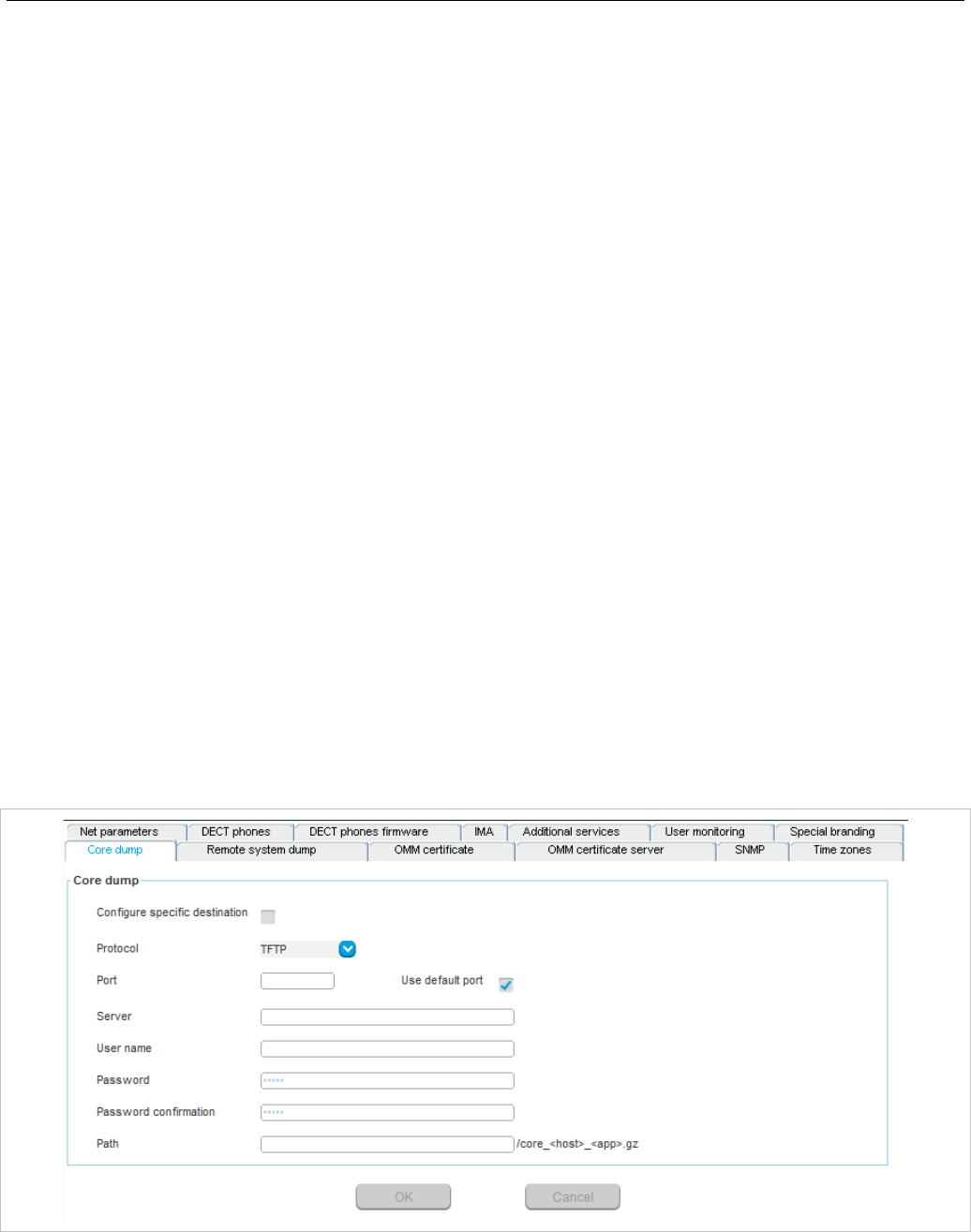
SIP-DECT OM System Manual
132
PP Branding key
• Active key: Displays the current branding key associated with the DECT phones.
• New key: Specifies the new branding key generated through the
DECTSuiteBrandingInstallation.exe utility.
Branding image URL
• Active: Enables the specific URL for downloading the customer_image.png file (as opposed to the
ConfigURL, which points to an external file server for all configuration and resource files).
• Protocol: Specifies the protocol used to fetch the image file.
• Port: Specifies the port of the external file server.
• Server: Specifies the IP address or name of the external file server.
• User name: Specifies the user name to authenticate on the external file server.
• Password: Specifies the password to authenticate on the external file server.
• Password confirmation: Confirms the password to authenticate on the external file server.
• Directory: Specifies the location of the image file on the external file server.
• Use common certificate configuration: Enables the use of the same certificate validation settings
for the image file URL as specified for the ConfigURL.
6.5.2.8 Core Dump
Fatal software problems may result in memory dumps, in core files. The IP RFP can transfer the core
files to a remote fileserver. With SIP-DECT 6.0 or later, you can configure a specific URL to an external
file server where core dump files should be transferred and stored. The Core dump URL is used by each
RFP connected to the OMM.
Without a configured Core dump URL, whether and where core files are transferred is dependent on
specific RFP settings. Without any special configuration, the files are transferred to the server that is
used to retrieve the system software (i.e., the directory of the boot image).
For a description of the parameters on the Core Dump tab, refer to the description of the System
settings page of the OMM Web service. The same parameters are described in the Core dump URL
section (section 5.4.1.12).
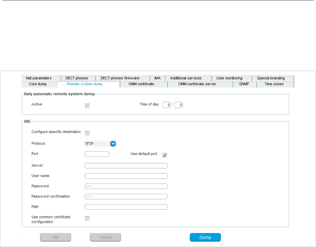
OM Management Portal (OMP)
133
6.5.2.9 Remote system dump
A system dump is a file that holds information about the OpenMobility Manager and all connected RFPs.
With the Remote System Dump feature, a system dump is transferred to a remote server. You can
configure a specific destination, otherwise the system configuration URL is used.
The system dump is generated manually by pressing the dump button or automatically at the configured
time. Please ensure that the used fileserver allows writing or creating system dumps.
For a description of the parameters on the Remote system Dump tab, refer to the description of the
System settings page of the OMM Web service. The same parameters are described in the System
dump section (section 5.4.1.11).
6.5.2.10 OMM Certificate
You can overwrite the hard-coded OMM certificate by importing a local certificate chain and a private key
file which may be password-protected. The OMM certificate will be used for incoming AXI and HTTPS
connections to the OMM services. If the OMM can be reached from the internet by a domain and an
appropriate CA certificate has been imported, no security warnings are displayed in web browsers that
trust the CA root certificate.
For more information on this feature, see section 7.10.
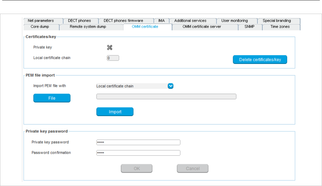
SIP-DECT OM System Manual
134
Certificates/key
• Private key: Indicates whether the OMM has a private key file (read-only).
• Local certificate chain: Indicates the number of local certificate chains deployed on the OMM (read-
only).
• Delete certificates/key: Allows you to delete any existing certificate or key files.
PEM file import
• Import PEM file with: Indicates the content type of the PEM file being imported. Available options are
“Local certificate chain” or “Private key”.
• File: Specifies the location of the PEM file to be imported.
• Import: Triggers the import of the specified PEM file.
Private key password
• Private key password: Specifies the password to be used for the private key file, if you want the file
to be password-protected.
• Password confirmation: Confirms the password for the private key file.
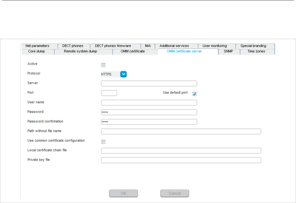
OM Management Portal (OMP)
135
6.5.2.11 OMM certificate server
OMM certificates can be updated automatically through configuration of a secure OMM certificate server
URL.
• Active: Enables the feature.
• Protocol: Specifies the preferred protocol (FTP, TFTP, FTPS, HTTP, HTTPS, SFTP).
• Server: Specifies the name or IP address of the external file server.
• Port: Specifies the certificate server’s port number
• Use default port: If selected, the default port associated with the selected protocol is used.
• User name: Specifies the user name to authenticate against the external file server.
• Password: Specifies the password to authenticate against the external file server.
• Password confirmation: Confirms the password to authenticate against the external file server.
• Path without filename: Specifies the path on the file server to the certificate files.
• Use common certificate configuration: Enables the use of the system-wide certificate validation
settings, as configured under the System -> Provisioning menu (see section 6.5.5).
• Local certificate file: Specifies the name of the PEM file on the external server including the local
certificate or a certificate chain.
• Private key file: Specifies the name of the PEM file on the external server including the local key.
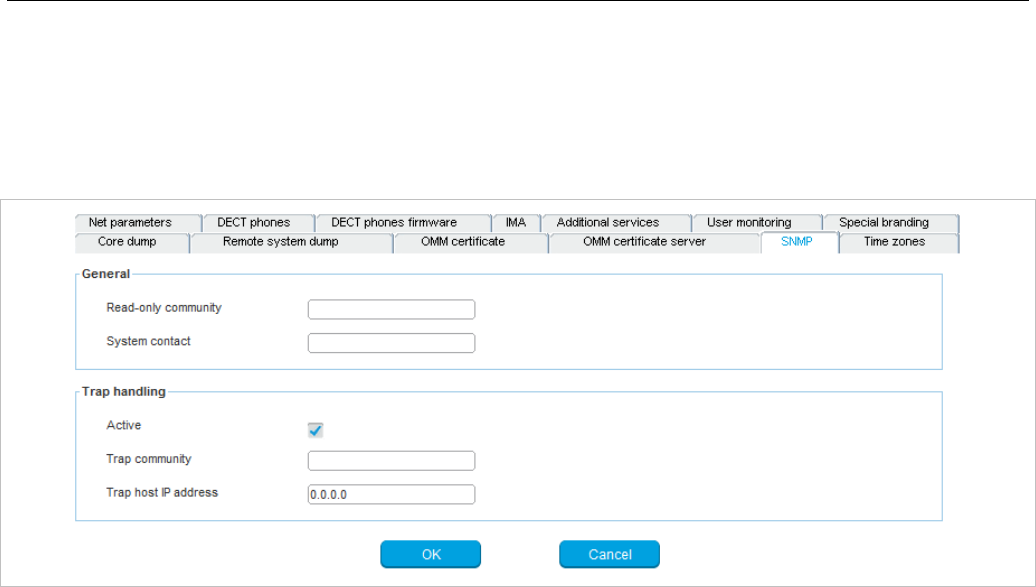
SIP-DECT OM System Manual
136
6.5.2.12 SNMP
To manage a larger RFP network, an SNMP agent is provided for each RFP. The SNMP agent provides
alarm information and allows an SNMP management system (such as “HP Open View”) to manage this
network. The SNMP sub menu of the OMP provides configuration of SNMP service settings.
For a description of the parameters on the SNMP tab, refer to the description of the SNMP menu of the
OMM Web service (see section 5.4.6).
6.5.2.13 Time zones
The OMM provides all available time zones on the Time zones tab. They are set with their known
daylight savings time rules adjusted to the Universal Coordinated Time (UTC) by default. The difference
to the UTC time is shown in the UTC difference field.
In addition, you can configure a new (free) time zone.
The date and time are provided by the OMM to the Mitel 142d and Mitel 600 DECT phones if the DECT
phone initiates a DECT location registration. The DECT phone initiates a DECT location registration
when:
• subscribing to the OMM
• entering the network again after the DECT signal was lost
• at power on
• silent charging feature is active at the phone and the phone is taken out of the charger
• after a specific time to update date and time
You can change the time zone rules for up to five time zones. The changes are saved in the
configuration file and are restored after each OpenMobility Manager startup.
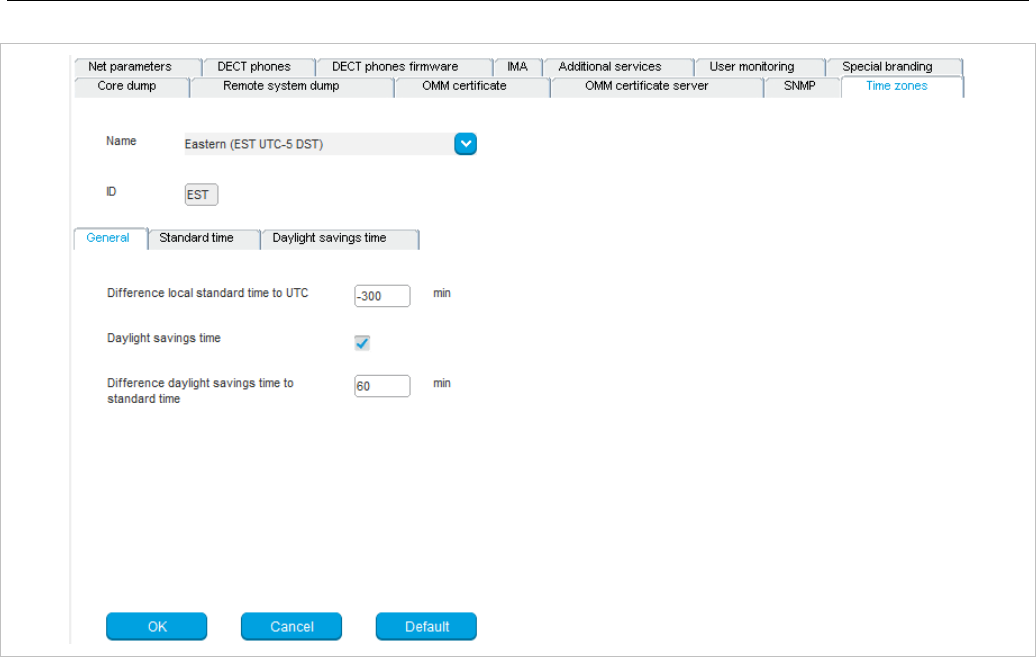
OM Management Portal (OMP)
137
General
• Difference local standard time to UTC: The difference (in minutes) between the local standard time
and UTC time.
• Daylight savings time: Enables or disables application of Daylight Savings Time (DST) for the time
zone. If disabled, the Standard time and Daylight savings time tabs are not accessible.
• Difference daylight savings time to standard time: The difference (in minutes) between Daylight
Savings Time (DST) and Standard Time for the time zone.
If the Daylight savings time parameter on the General tab is enabled, you can change the standard
time and the daylight savings time (DST) of a time zone in the Standard time and Daylight savings
time tabs. If the time zone has no DST, only the UTC difference can be configured. For the DST both
points of time (begin of standard time and begin of daylight savings time) must be specified exactly.
Therefore a certain day in the month or a certain week day in a month can be used.
The following commands are available to edit time zones:
• OK: Confirm the changed time zone settings.
• Cancel: Cancels the operation and resets the changed time zone back to the default setting.
• Default: Resets all individual time zone settings to the default values and deletes the changed time
zone rules in the configuration file.
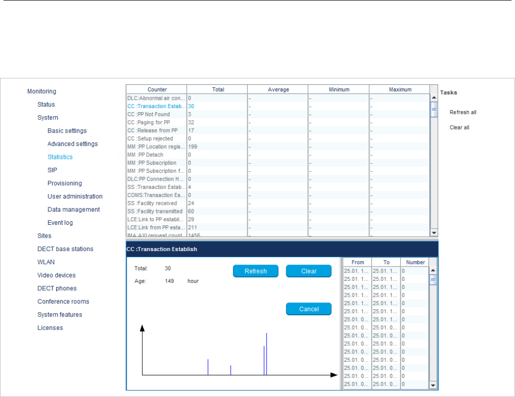
SIP-DECT OM System Manual
138
6.5.3 “STATISTICS” MENU (MONITORING MODE ONLY)
The Statistics menu provides numerous system statistics counters which can be used to check system
behavior. The menu is only available in Monitor Mode.
Statistic counters beginning with “+” are counters that are taken over by standby OMM in case of a
failover. All other counters are reset to the defaults in case of a failover. For more details about the
standby feature, see section 7.15.
The following tasks can be performed:
• Refresh all: request OMM update for all statistics counters.
• Clear all: reset all statistics counters in OMM.
If a statistics counter is selected in the table, it is shown in a detail panel. This detail panel provides all
available information for this statistics counter. You can:
• update this single statistics counter by pressing the Refresh button, or
• reset this single statistics counter by pressing the Clear button.
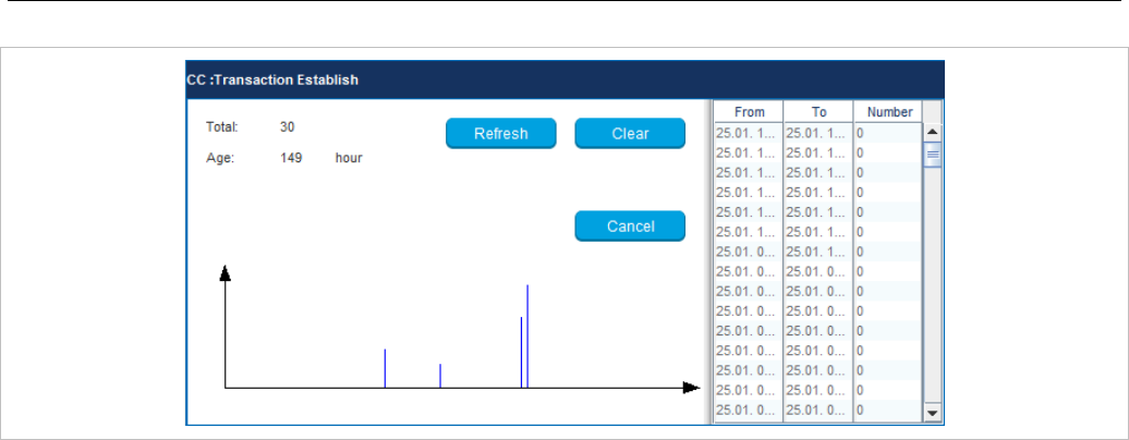
OM Management Portal (OMP)
139
6.5.4 “SIP” MENU
The SIP menu covers global settings for SIP signaling and RTP voice streams and contains the following
tabs:
• Basic settings (see section 6.5.4.1)
• Advanced settings (see section 6.5.4.2)
• Registration traffic shaping (see section 6.5.4.3)
• Backup settings (see section 6.5.4.4)
• RTP settings (see section 6.5.4.5)
• DTMF settings (see section 6.5.4.6)
• Intercom Push-to-talk (see section 6.5.4.7)
• Supplementary services (see section 6.5.4.8)
• Conference (see section 6.5.4.9)
• Security (see section 6.5.4.10)
• Certificate server (see section 6.5.4.11)
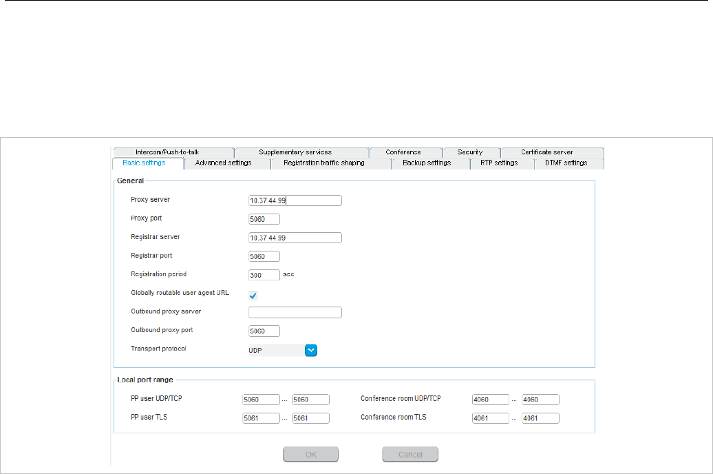
SIP-DECT OM System Manual
140
6.5.4.1 Basic settings
For a description of the parameters on the Basic settings tab, see the description of the System -> SIP
menu of the OMM Web service. The same parameters are described in the Basic settings section
(section 5.4.3.1).
In addition, the following parameters (related to SIP multiport support) are available on the Basic
settings tab:
Local port range
• DECT phone user UDP/TCP: The port range to be used for DECT users when UDP/TCP is used as
the transport protocol. The default is 5060 – 5060.
• DECT phone user TLS: The port range to be used for DECT users when TLS is used as the
transport protocol. The default is 5061 – 5061.
• Conference room UDP/TCP: The port range to be used for Conference Rooms when UDP/TCP is
used as the transport protocol. The default is 4060 – 4060.
• Conference room TLS: The port range to be used for DECT users when TLS is used as the
transport protocol. The default is 4061 – 4061.
Note: There are certain rules to note when configuring port ranges; see
section 3.7 for more information.
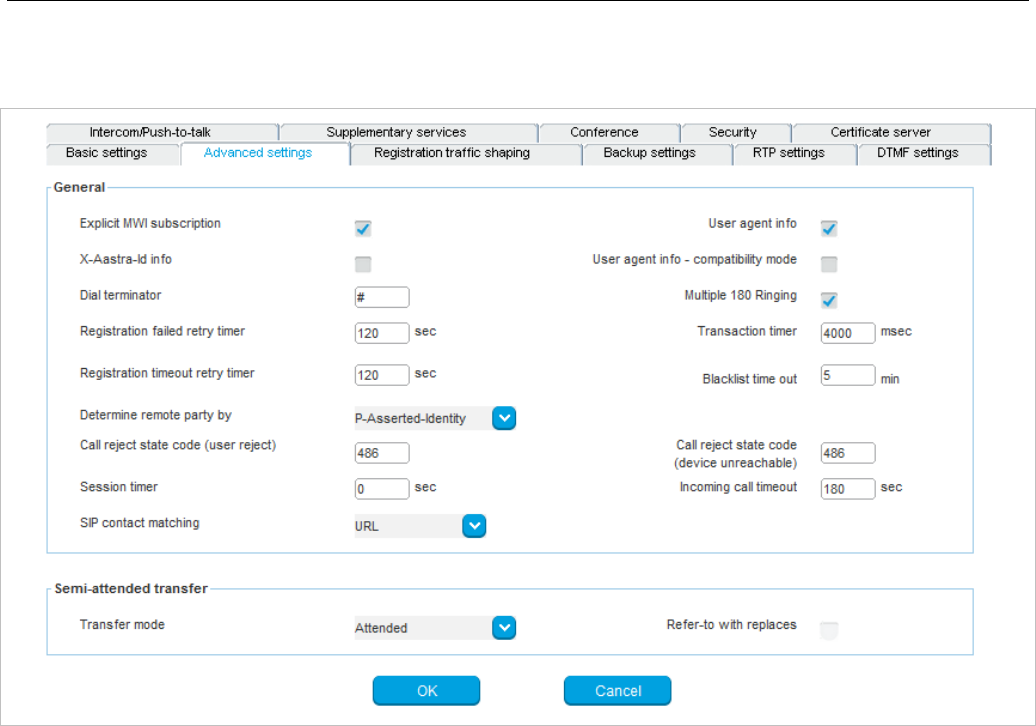
OM Management Portal (OMP)
141
6.5.4.2 Advanced settings
You can set several additional SIP parameters on the Advanced settings tab.
For a description of the parameters on the Advanced settings tab, refer to the description of the
System -> SIP menu of the OMM Web service. The same parameters are described in the Advanced
settings section (section 5.4.3.2).
In addition, the following parameters are available in the OMP only:
• X-Aastra-Id info: Enable or disable inclusion of the private X-Aastra-Id header in each SIP
REGISTER message.
• User agent info – compatibility mode: If the User agent info option is enabled, the OMM sends
information on his version inside the SIP User-Agent/Server headers; this parameter ensures
backward compatibility with version information used in older SIP-DECT software releases.
6.5.4.3 Registration traffic shaping
Registration traffic shaping parameters allow you to limit the number of simultaneous SIP registrations at
startup/fail over of the OMM. This feature is always activated because disabling it may overload the
OMM or the call server.
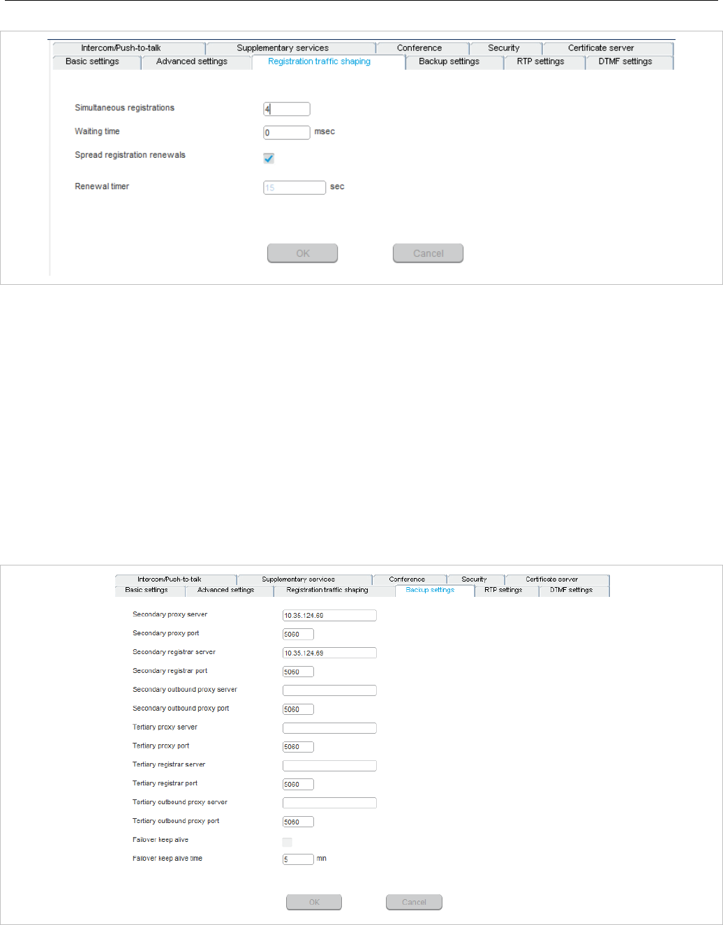
SIP-DECT OM System Manual
142
For a description of the parameters on the Registration traffic shaping tab, see the description of the
System -> SIP page of the OMM Web service. The same parameters are described in the Registration
traffic shaping section (section 5.4.3.5).
6.5.4.4 Backup settings
To increase the operational availability of the system in critical environments like hospitals, the OMM
offers a failover redundancy mechanism for the SIP server. In addition to the primary proxy, outbound
proxy and registrar server, you can configure two additional levels of backup servers (secondary and
tertiary servers).
The OMM failover behavior in detail depends on the backup server settings set here. A full description of
the behavior and deployment hints can be found in section 7.20.3.
• Secondary proxy server / port, Secondary registrar server / port, Secondary outbound server /
port: Enter the parameters for the secondary server in these fields.
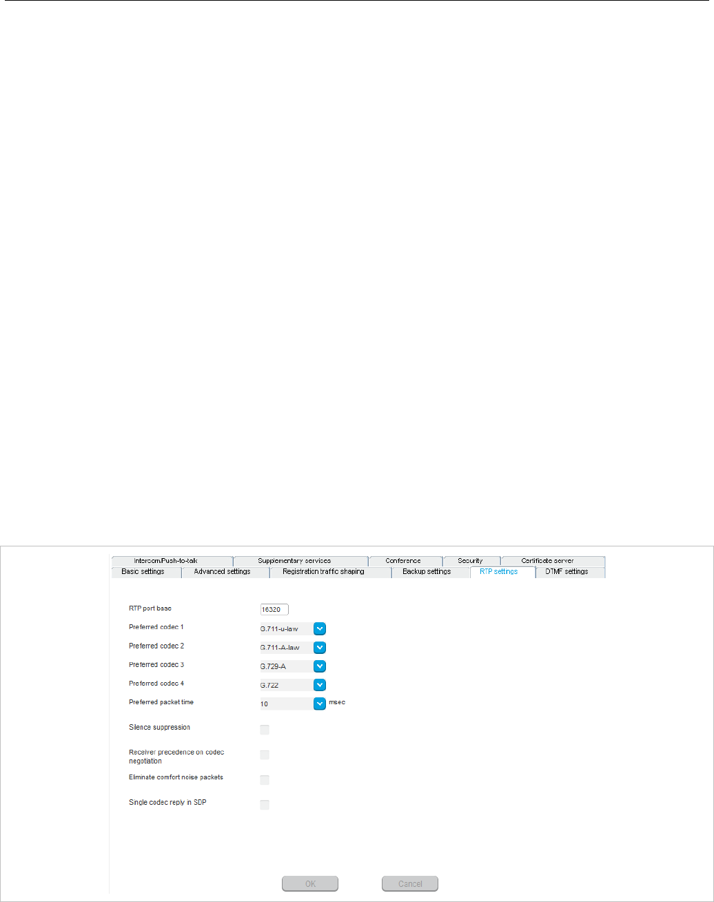
OM Management Portal (OMP)
143
• Tertiary proxy server / port, Tertiary registrar server / port, Tertiary outbound server / port:
Enter the parameters for the tertiary server in these fields.
Note: Server addresses can be configured as IP addresses, names or
a fully qualified domain names. It is possible to configure a
mixture of IP addresses, names or fully qualified domain names
for the different servers. If fully qualified domain names are
configured and the respective port setting is configured to zero
(“0”), DNS SRV queries will be performed to locate a list of
servers in the domain (see 0).
• Failover keep alive: The keep-alive mechanism allows transferring all users registered on a failed
server (failover) to secondary/tertiary servers as well as automatically switching back to primary
servers. Otherwise, failover is executed only single users. Enable this option if you want to use this
feature (default: off).
• Failover keep alive time: For each registration target, a user could be registered successful with, a
keep alive procedure is started. Enter the time in this field after which a new keep-alive procedure
must be started (1-60 minutes, default 10 min.).
For a detailed description of the keep-alive mechanism see section 7.20.4.
6.5.4.5 RTP settings
For a description of the parameters on the RTP settings tab, see the description of the System -> SIP
page of the OMM Web service. The same parameters are described in the RTP settings section
(section 5.4.3.3).
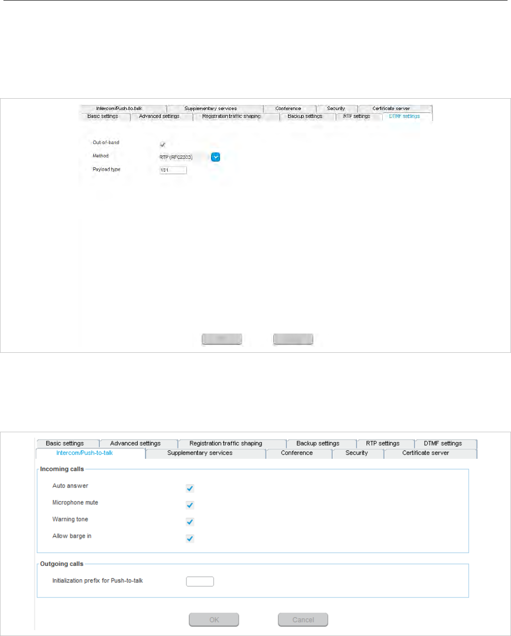
SIP-DECT OM System Manual
144
6.5.4.6 DTMF settings
For a description of the parameters on the DTMF settings tab, see the description of the System -> SIP
page of the OMM Web service. The same parameters are described in the DTMF settings section
(section 5.4.3.4).
6.5.4.7 Intercom Push-to-talk
You can set global auto-answer settings on the Intercom Push-to-talk tab. For more information on this
feature, see section 3.35.
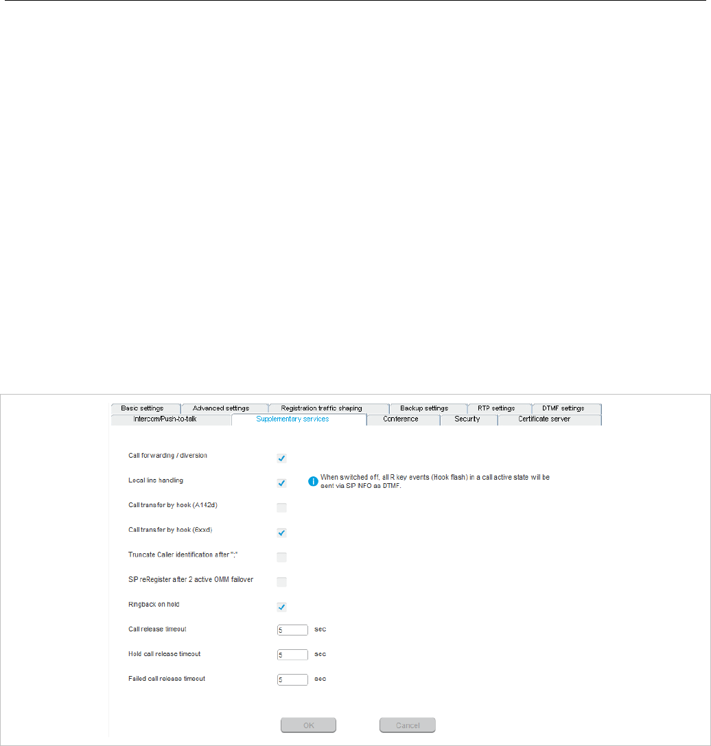
OM Management Portal (OMP)
145
Incoming calls
• Auto answer: Enables or disables auto-answer on incoming calls.
• Microphone mute: Enables or disables microphone muting when incoming calls are automatically
answered.
• Warning tone: Enables or disables warning tone on incoming call. A short ringtone is played if there
are no active calls. If there is an active call in a “barge in” situation, the ringing will be in-band
• Allow barge in: Allows/disallows “barge-in” on existing calls.
Outgoing calls
• Initialization prefix for push-to-talk: String to be entered when initiating an intercom call. An empty
string indicates that the DECT phone cannot initiate an intercom call.
6.5.4.8 Supplementary services
For a description of the parameters on the Supplementary services tab, see the description of the
System -> SIP page of the OMM Web service. The same parameters are described in the
Supplementary Services section (section 5.4.3.6).
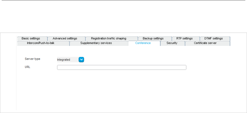
SIP-DECT OM System Manual
146
6.5.4.9 Conference
You can define the conference mode globally for all SIP-DECT users on the Conference tab. For more
information on the Conferencing feature, see section 7.21.
• Server type: Specifies the operational mode for the conference server. Available options are:
- None: neither external nor internal conference server is used.
- Integrated: the conference server integrated in the SIP-DECT system is used.
- External: an external conference server (e.g., Broadsoft) is used.
- External – Blind Transfer: an external conference server is used (e.g. MiVoice Business). The
initiation of the conference is signaled as a blind transfer to the destination specified in the URL
parameter.
• URL: Specifies the URL for the conference server.
6.5.4.10 Security
For a description of the parameters on the Security tab, see the description of the System -> SIP page
of the OMM Web service. The same parameters are described in the Security section (section 5.4.3.8)
and the Manual Import section (section 5.4.3.10).
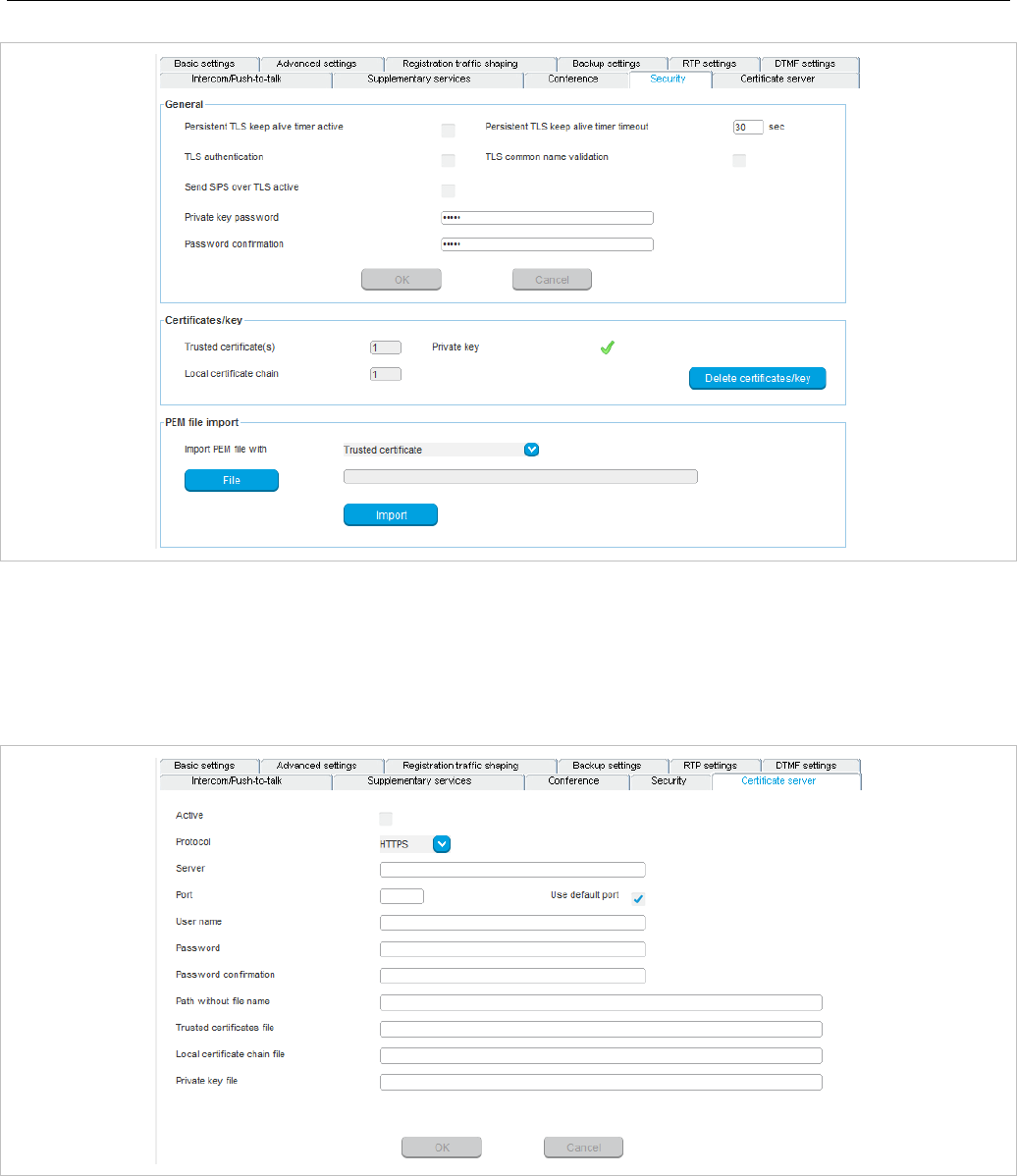
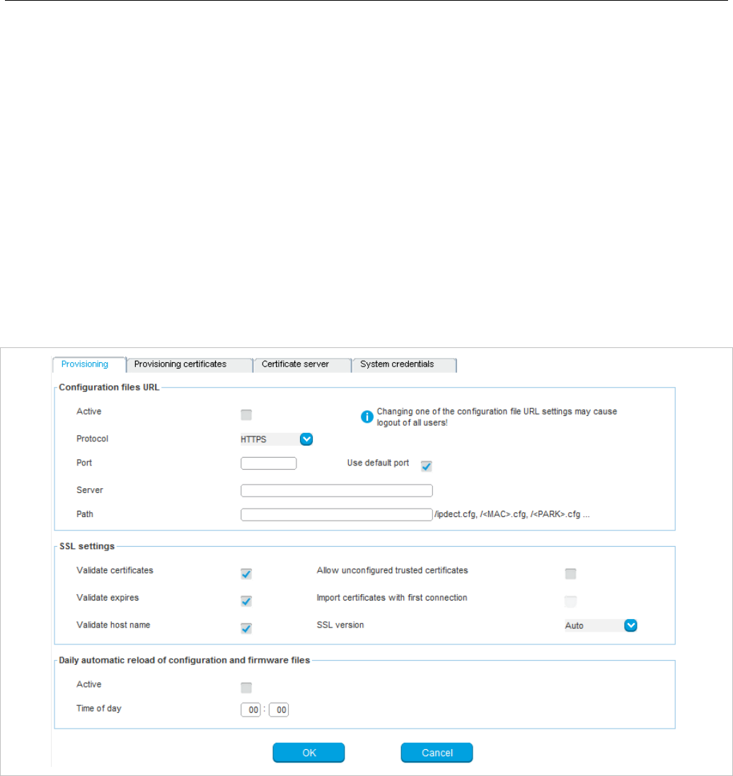
SIP-DECT OM System Manual
148
6.5.5 ”PROVISIONING” MENU
SIP-DECT supports provisioning through external configuration files. With SIP-DECT 6.0 or later, you
can configure a URL for an external file server, from which all configuration files can be downloaded. The
configured provisioning server URL is used for secure connections to the file server to retrieve
configuration or firmware files.
The Provisioning menu contains settings related to the provisioning server and contains the following
tabs:
• Provisioning (see section 6.5.5.1)
• Provisioning certificate (see section 6.5.5.2)
• Certificate server (see section 6.5.5.3)
• System credentials (see section 6.5.5.4)
6.5.5.1 Provisioning
Configuration files URL
• Active: Enable the configuration file URL feature.
• Protocol: The protocol to be used to fetch the configuration files.
• Port: Provisioning server’s port number.
• Use default port: If selected, the default port associated with the selected protocol is used.
• Server: IP address or name of the provisioning server.
• Path: Path to the configuration and resource files on the provisioning server.

OM Management Portal (OMP)
149
SSL settings
• Validate certificates: Enables or disables certificate validation. If enabled, the server certificate is
validated against trusted CA’s (signed by a CA from the Mozilla CA certificate list) and the configured
trusted certificates.
• Validate expires: Enables or disables the validation of certificate expiry. When this parameter is
enabled, the client verifies whether or not a certificate has expired prior to accepting the certificate.
• Validate host name: Enables or disables the validation of hostnames on the OMM.
• Allow unconfigured trusted certificates: If enabled, this parameter disables any server certificate
validation as long as no trusted certificate was imported into the OMM. AXI commands in a received
configuration file may import such trusted certificates into the OMM.
• Import certificates with first connection: If enabled (in conjunction with the Allow unconfigured
trusted certificates parameter), the trusted certificate will be imported from the cert chain delivered in
the server response without any validation, as long as no trusted certificate was imported previously
into the OMM.
• SSL version: The SSL protocol version to use for the configuration file server connection. Available
options are: TLS1.0, TLS1.1, TLS1.2 or AUTO, where AUTO accepts all protocol versions.
Daily automatic reload of configuration and firmware files
• Active: Enables automatic reload of the configuration and resource files on a daily basis, at the
specified time.
• Time of day: Time for scheduled reload of configuration and firmware files.
6.5.5.2 Provisioning certificates
Provisioning certificates are used for secure connections to configuration or firmware file servers that
support mutual authentication.
A trusted certificate chain is used by the OMM to validate the server. This is required if the server has no
certificate derived from a trusted CA root certificate, where the OMM uses the Mozilla CA Certificate List.
If no server certificate is available, the validation against trusted and CA certificates can be disabled in
the certificate validation options (only encrypted TLS connection).
The local certificate chain plus the private key are provided from the OMM to servers requesting mutual
authentication. The private key file may be password protected.
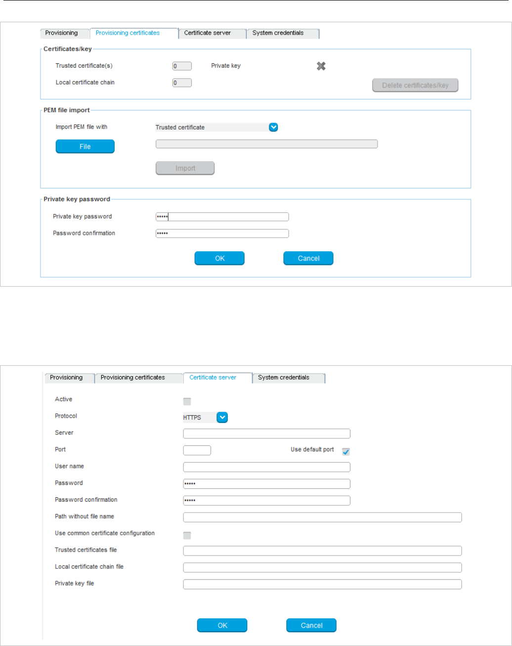
SIP-DECT OM System Manual
150
6.5.5.3 Certificate server
The provisioning certificates can be updated automatically through configuration of a secure provisioning
certificate server URL.
• Active: Enable automatic updating of certificates the feature.
• Protocol: Specifies the preferred protocol (FTP, TFTP, FTPS, HTTP, HTTPS, SFTP)
• Server: Specifies the name or IP address of the external file server.
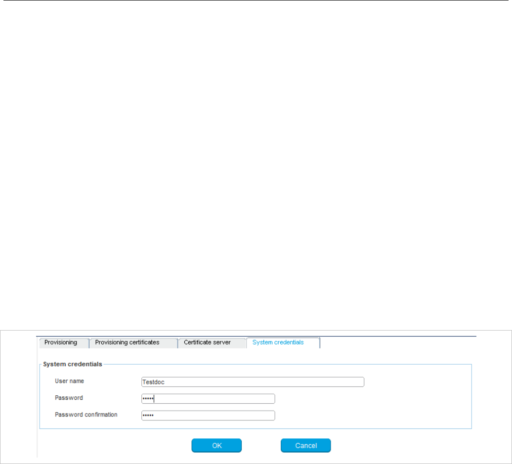
OM Management Portal (OMP)
151
• Port: Specifies the certificate server’s port number
• Use default port: If selected, the default port associated with the selected protocol is used.
• User name: Specifies the user name to authenticate against the external file server.
• Password: Specifies the password to authenticate against the external file server.
• Password confirmation: Confirms the password to authenticate against the external file server.
• Path without filename: Specifies the path on the file server to the certificate files.
• Use common certificate configuration: Enables the use of the system-wide certificate validation
settings, as configured on the System -> Provisioning -> Provisioning certificates page (see
section 6.5.5.2)
• Trusted certificate file: Specifies the name of the PEM file on the specified server, including the
trusted certificates.
• Local certificate file: Specifies the name of the PEM file on the external server including the local
certificate or a certificate chain.
• Private key file: Specifies the name of the PEM file on the external server including the local key.
6.5.5.4 System credentials
System credentials are used to retrieve configuration and resource files from the configured provisioning
server for protocols supporting authentication or servers requesting authentication. For HTTP/HTTPS,
basic and digest authentication are supported.
• User name: Specifies the user name for authentication against the provisioning server.
• Password: Specifies the password for authentication against the provisioning server
• Password confirmation: Confirms the password for authentication against the provisioning server.
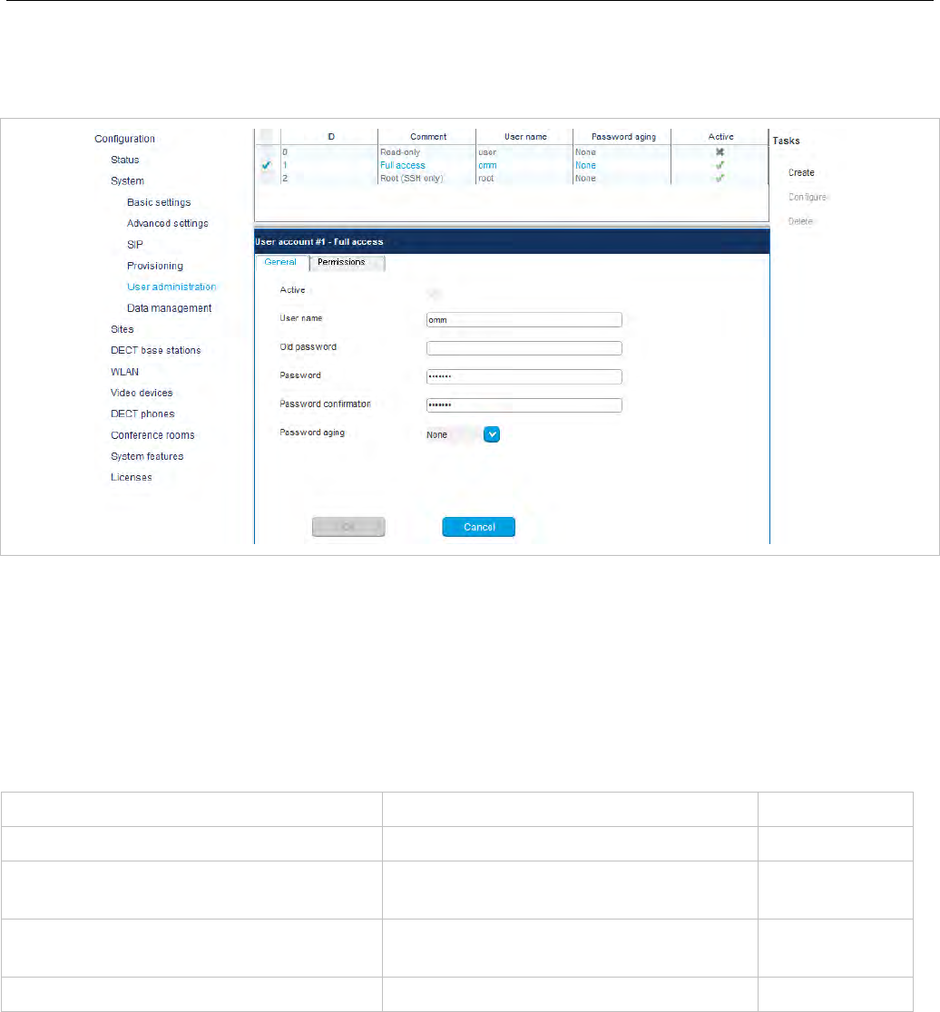
SIP-DECT OM System Manual
152
6.5.6 “USER ADMINISTRATION” MENU
In the User administration menu you configure the OMM user accounts.
The three user accounts “Full access”, “Read-only” and “Root (ssh only)” available via the User
administration page of the OMM Web service can also be configured in the OMP. These three
predefined user accounts cannot be removed or renamed. Only the “Read-only” account can be
activated and deactivated. The permissions are fixed. This is consistent with the OMM WEB service. The
meaning of the different account types is described in section 7.17.1. In addition, the OMP allows to
create additional user accounts (login and password) and to assign specific permissions.
The tasks which can be performed are mode-dependant.
Configuration mode Monitor mode See section
Create: create new user account 6.5.6.1
Configure: configure selected user
account in detail panel 6.5.6.2
Show details: shows selected user
account in detail panel 6.5.6.3
Delete: delete selected user account 6.5.6.4
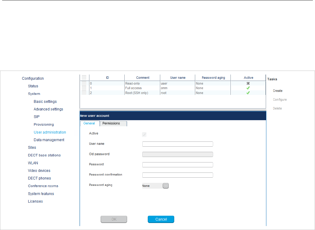
OM Management Portal (OMP)
153
6.5.6.1 Creating New User Accounts
It is possible to create additional user accounts (login and password) and to assign specific permissions.
These accounts are mainly designed to have specific login data and permissions for applications which
are using OM AXI to connect with the OMM.
Note: Individual user accounts cannot be used for a login to the OMM
Web service nor SSH.
Adding individual user accounts is only possible in Configuration Mode. To add a user account, do the
following:
1 In the Tasks bar click on the Create command.
The New user account panel opens. It provides various tabs where the account data must be
entered.
2 Configure the user account, see parameter description below.
3 Press the OK button.
The following parameters can be set in the tabs of the New user account panel:
General
For a description of the parameters which can be set in the General tab, see the description of the User
administration page of the OMM Web service (see section 6.5.6.).
Permissions
The permissions for an individual user account can be set independent from any license status even if
some of the permissions can only been used with an appropriate license.
If an application connects with the OMM via OM AXI, then the permissions been sent from the OMM to
the application is the result of the configured permissions for this account and the actual license status.
For more information please see the OM Application XML Interface (OM AXI) specification /31/.

SIP-DECT OM System Manual
154
The permissions have the following meaning:
Permission Description
Read Read OMM data (OM AXI get requests)
Write Set OMM data (OM AXI set requests)
Messaging info Sent messages with priority “Info”
Messaging Sent messages with priority “Low”, “Normal”
and “High”
Messaging emergency Sent messages with priority “Emergency”
Messaging locating Sent messages with priority “LocatingAlert”
Locating Permission to query the position of DECT
phones and to track DECT phone positions
Monitoring Permission to monitor various technical
aspects of the mobility system
Video Permission for video streaming
6.5.6.2 Changing a User Account
Changing user accounts is only possible in configuration mode. To change the configuration of an
existing user account, do the following:
1 Select the appropriate user account in the account table.
2 In the Tasks bar click on the Configure command.
3 Change the user account parameters (see parameter descriptions in section 6.5.6.1).
4 Press the OK button.
Please note: The predefined user accounts “Full access”, “Read-only” and “Root (ssh only)”
user accounts cannot be renamed. Also their permissions are fixed and cannot be
changed.
6.5.6.3 Viewing User Account Details
You can view the configuration of a user account in monitor mode. Proceed as follows:
1 Select the appropriate user account in the table.
2 In the Tasks bar click on the Show details command.
The user account data is displayed in the user account detail panel.
3 To close the user account detail panel, click the Cancel button.

OM Management Portal (OMP)
155
6.5.6.4 Deleting User Accounts
Deleting user accounts is only possible in configuration mode. To delete one or more existing user
accounts proceed as follows:
1 Select the appropriate account(s) in the user account table by activating the corresponding
checkbox(es).
2 In the Tasks bar click on the Delete command.
3 Confirm the displayed prompt with OK.
Please note: The predefined user accounts “Full access”, “Read-only” and “Root (ssh only)”
user accounts cannot be removed.
6.5.7 “DATA MANAGEMENT” MENU
The Data management menu provides access to data related to import and export features.
The menu provides the settings in several tabs:
• Auto DB export (see section 6.5.7.1)
• User data import (see section 6.5.7.2)
• DECT phones synchronization (see section 6.5.7.3)
• Manual DB import (see section 6.5.7.4)
• Manual DB export (see section 6.5.7.5)
• Maintenance (see section 6.5.7.6)
• IMA (see section 6.5.7.7)
6.5.7.1 Automatic DB export
The automatic database export feature allows an automatic database backup to an external server for
each configuration modification.
Please note: Synchronization with an NTP server is mandatory for an automatic database
export. For NTP server configuration, see section 7.5.4 and section 7.6.
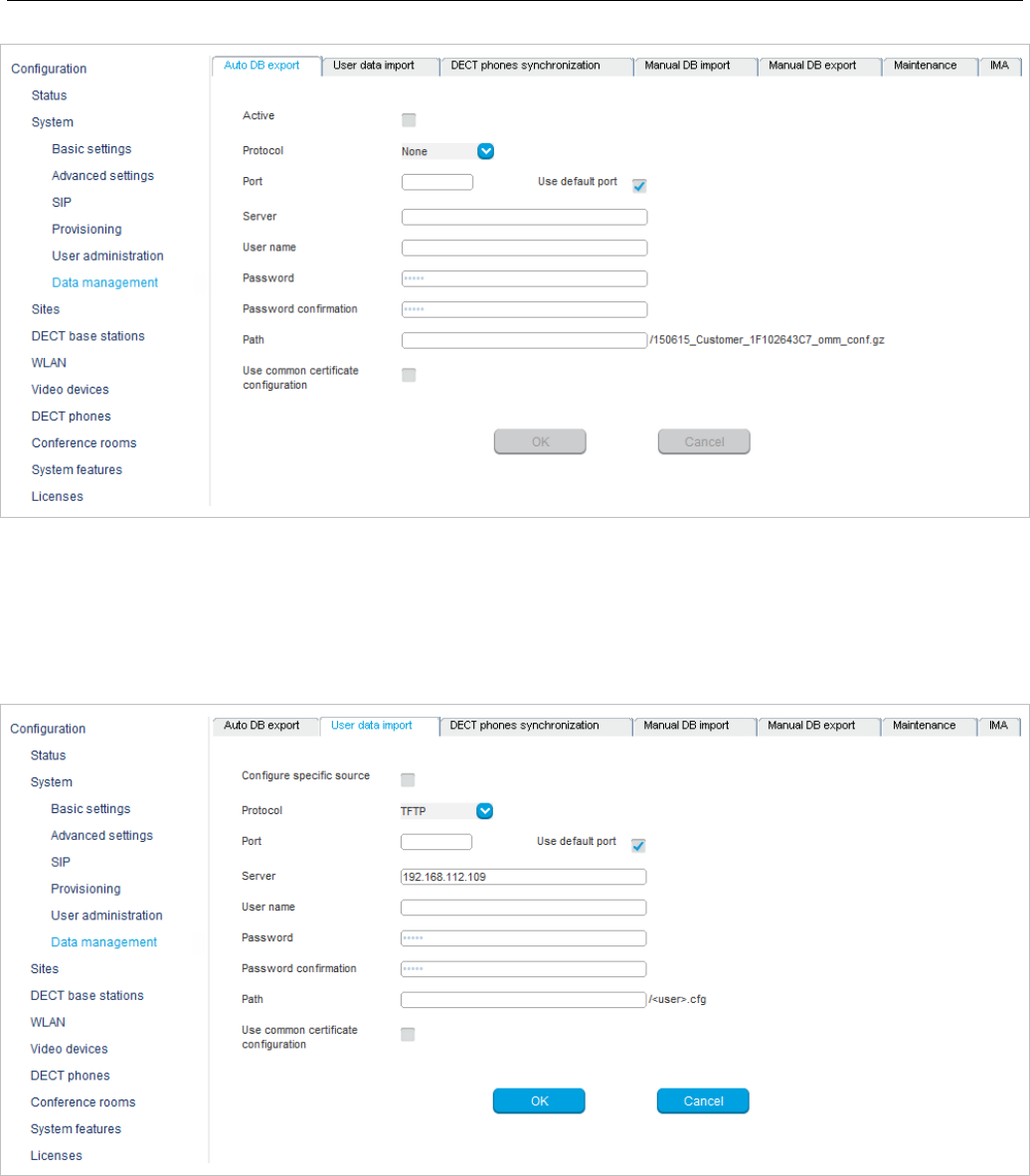
SIP-DECT OM System Manual
156
For a description of the parameters on the Automatic DB export tab, see the description of the System
-> Data management page of the OMM Web service. The same parameters are described in the
Automatic Database Export section (section 5.4.7.3).
6.5.7.2 User data import
The user data import feature allows the import of user data from an external provisioning server.
• Configure specific source: Enables the specific URL to an external file server for retrieving the user
data file.
• Protocol: Specifies the preferred protocol.
• Port: Specifies the port on the server.
• Server: Specifies the IP address or the name of the server.
• User name, Password, Password confirmation: Specifies the credentials for the server.
• Path: Specifies the path to the file containing the user data.
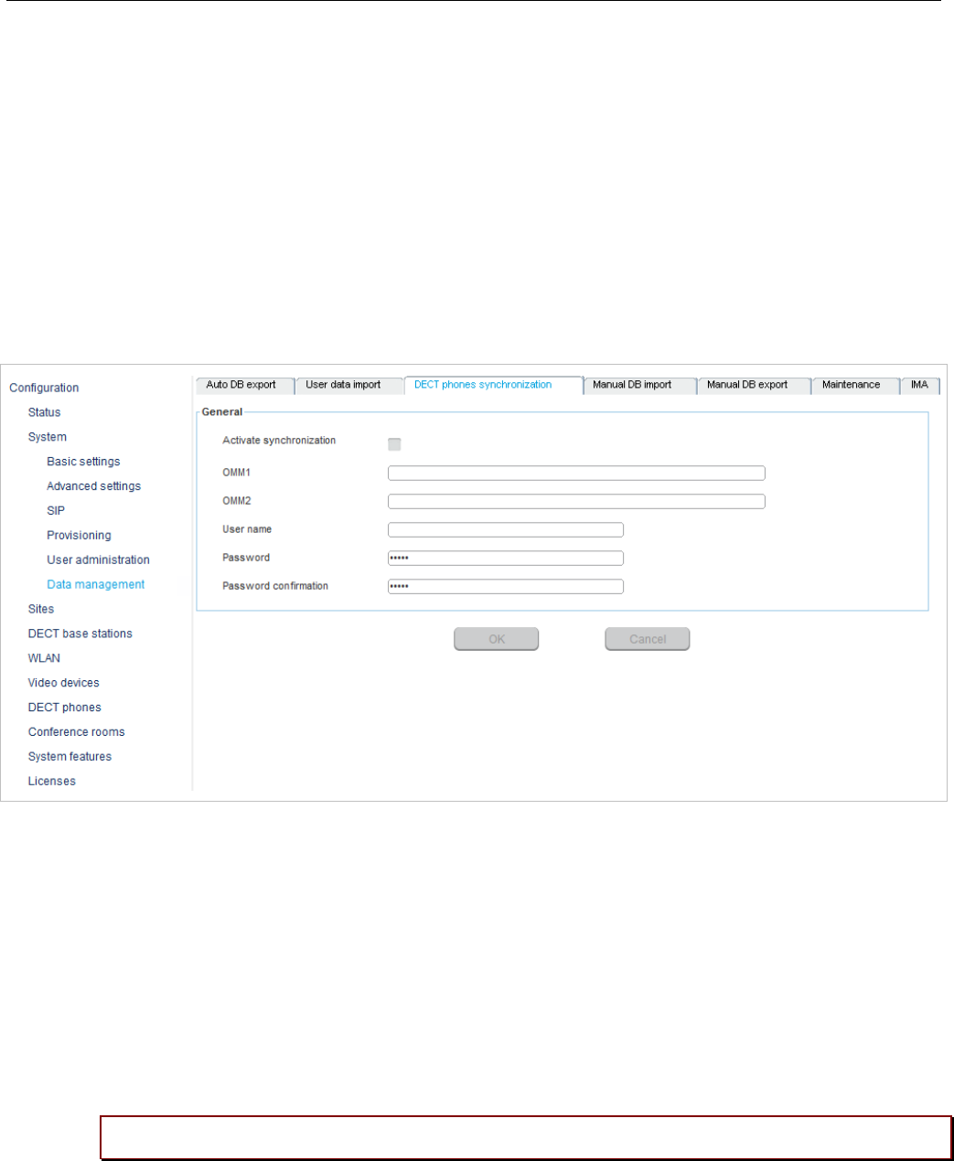
OM Management Portal (OMP)
157
• Use common certificate configuration: Enables the use of the system-wide certificate validation
settings, as configured on the System -> Provisioning -> Certificates page (see section 5.4.2.5).
For further information on the user data import, see the OM DECT Phone Sharing and Provisioning
Guide.
6.5.7.3 DECT phones synchronization
The user data synchronization feature ensures that all user and device database information is
distributed to all OMM instances in the system. Each peripheral OMM must have a connection to the AXI
interface of the central OMM (and the standby central OMM, if configured) to send and receive updated
user data information. Specify the same user credentials used to access the central OMM via the OMP.
For more information on this feature, see section 7.16.
• Activate synchronization: Enable user data synchronization for the OMM.
• OMM1: Specifies the IP address of the central OMM.
• OMM2: Specifies the IP address of a second central OMM, in the case of a standby configuration.
• User name: Specifies the user name required to access the central OMM.
• Password: Specifies the password required to access the central OMM.
• Password confirmation: Confirms the password required to access the central OMM.
6.5.7.4 Manual DB import
The manual database import feature allows the import of an OMM database.
Please note: A manual import of a database results in a reset of the OMM.
For a description of the parameters on the Manual DB import tab, see the description of the System ->
Data management page of the OMM Web service. The same parameters are described in the Manual
Database Import section (section 5.4.7.1).
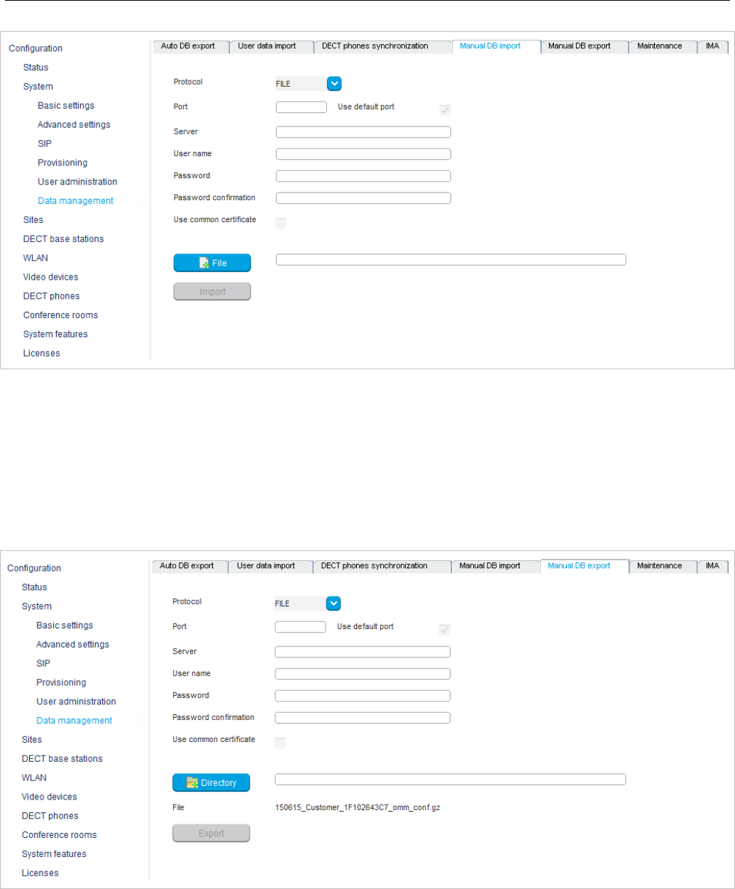
SIP-DECT OM System Manual
158
6.5.7.5 Manual DB export
The manual database export feature allows a manual database backup to an external server.
For a description of the parameters on the Manual DB export tab, see the description of the System ->
Data management page of the OMM Web service. The same parameters are described in the Manual
Database Export section (section 5.4.7.2).
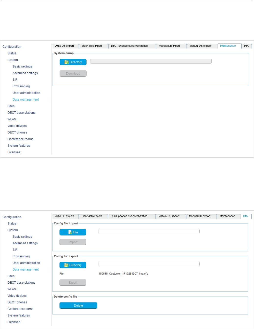
OM Management Portal (OMP)
159
6.5.7.6 Maintenance
In the Maintenance panel, you can perform a system dump, for example, for product support information
purposes. A file “sysdump.txt” is created in the selected directory. Click the Directory button to select
the directory, then click the Download button to start the system dump.
6.5.7.7 IMA
You can upload an IMA configuration file manually. To validate the existing configuration, the IMA
configuration can be also downloaded. An uploaded IMA configuration may be overwritten if a server for
the IMA configuration file is configured or if the ‘ima.cfg’ is available on the provisioning server. The IMA
configuration can be deleted regardless of its source.
• Config file import
To upload an IMA configuration file, click the File button to browse to the file, then click Import.
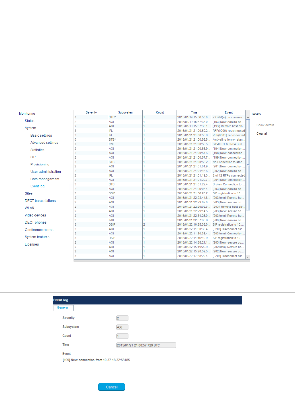
SIP-DECT OM System Manual
160
• Config file export
To download the current IMA configuration file, click the Directory button to select the destination
directory, then click Export.
• Delete config file
To delete the IMA configuration file, click Delete.
6.5.8 “EVENT LOG” MENU
The Event Log menu provides information about system events. The menu is only available in Monitor
Mode.
6.5.8.1 Event log detail panel
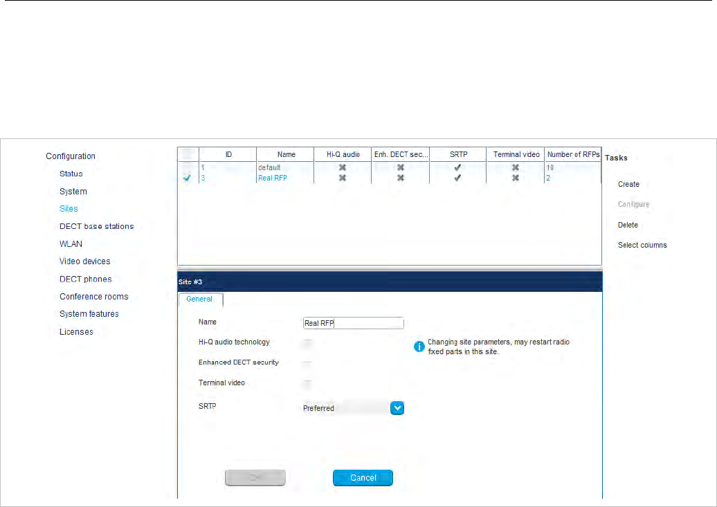
OM Management Portal (OMP)
161
6.6 “SITES” MENU
DECT base stations can be grouped into different sites. The Sites menu allows configuration and display
of configured sites. An empty system has one predefined site (ID: 1) named “default”. The system
requires a minimum of one site.
A site consists of the following parameters:
• ID: Identification number of the site. A value between 1 and 250 is possible. If no value is given, the
OMM selects the next free ID.
• Name: The name of the site.
• Hi-Q audio technology /
Enhanced DECT security /
Terminal video /
SRTP: These capabilities must be enabled or disabled specific for every site.
– In sites, which are configured to provide this functionality, exclusively RFP 35/36/37 IP and
RFP 43 WLAN are applicable.
– In sites without this capability, it is allowed to mix these new RFP types with RFP 32/34 IP and
RFP 42 WLAN.
• Number of RFPs: The number of RFPs which are assigned to this site.
The following tasks can be performed:
• Create: create a new site in the General tab.
• Configure: configure an existing site in the General tab.
• Delete: delete selected sites (only sites without assigned RFPs can be deleted).
• Show details (only in Monitor Mode): shows configuration of a selected site in the General tab.
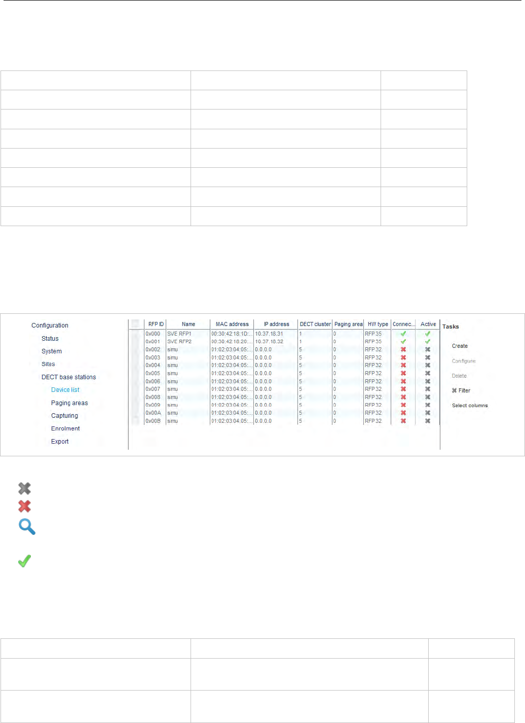
SIP-DECT OM System Manual
162
6.7 “DECT BASE STATIONS” MENU
DECT base stations can be configured and viewed in the DECT base stations menu.
Configuration mode Monitor mode See section
Device list Device list 6.7.1
Paging areas 6.7.2
Capturing 6.7.3
Enrolment 6.7.4
Export 6.7.5
Sync view 6.7.6
Statistics 6.7.7
6.7.1 “DEVICE LIST” MENU
The Device list panel displays all configured DECT base stations in a table. The device list is available
in Configuration Mode and Monitor Mode.
The Active column shows the following states:
• – DECT is not enabled and/or RFP not connected.
• – DECT is enabled and RFP connected, but DECT has not been activated yet.
• – DECT is enabled and RFP is connected, but RFP is not synchronized and searches for other
synchronized RFPs.
• – DECT is enabled and RFP is connected and synchronized.
Note: If the Active column is not displayed, you can activate it in the
Select columns dialog, see section 6.7.1.7.
The tasks you can perform are mode-dependant.
Configuration mode Monitor mode See section
Create: create new base station in
detail panel 6.7.1.2
Configure: configure selected base
station in detail panel 6.7.1.3
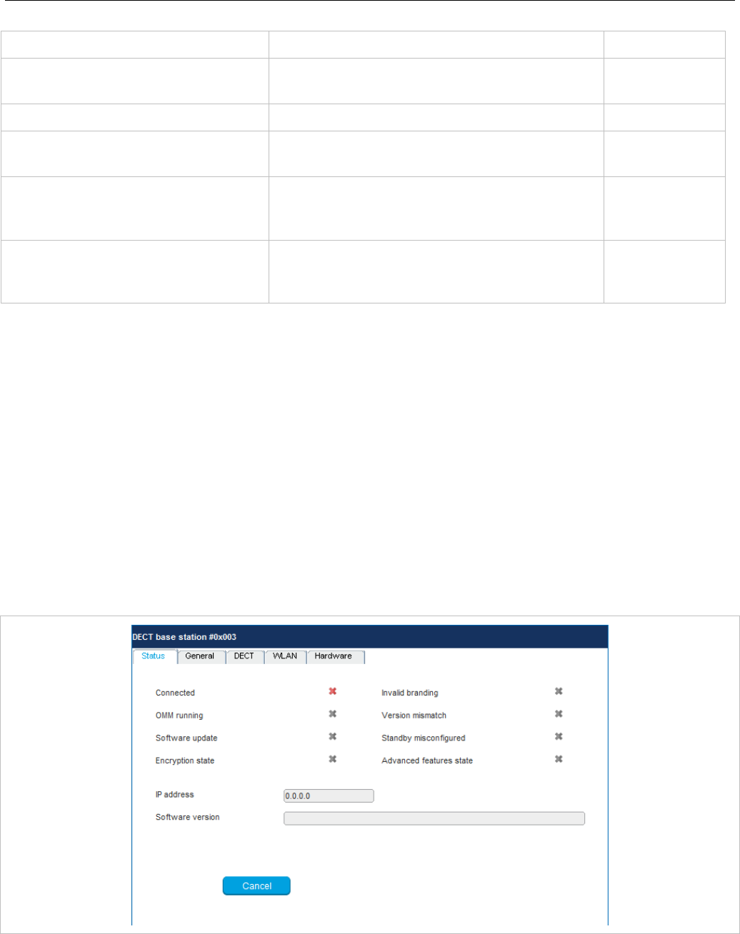
OM Management Portal (OMP)
163
Configuration mode Monitor mode See section
Show details: show selected base station in
detail panel 6.7.1.4
Delete: delete selected RFP 6.7.1.5
Show sync. relations: show synchronization
relation for selected RFPs 6.7.1.6
Select columns: select
columns/parameters to be shown in
RFP table
Select columns: select columns/parameters
to be shown in RFP table 6.7.1.7
Filter: show only RFP datasets in
table which contain a special search
string
Filter: show only RFP datasets in table which
contain a special search string 6.7.1.8
6.7.1.1 DECT Base Station Detail Panel
The DECT base station detail panel is used for configuration/display of RFP settings and creation of new
RFP datasets.
To call up the DECT base station detail panel, do one of the following:
• choose one of the commands in the task bar on the right of the DECT base stations panel (Create,
Configure, or Show details)
• double-click on the appropriate RFP entry in the RFP table.
The DECT base station detail panel contains the following parameter groups sorted in different tabs.
“Status” tab
This tab is only available in Monitor Mode. It shows system status information relating to the selected
DECT base station.
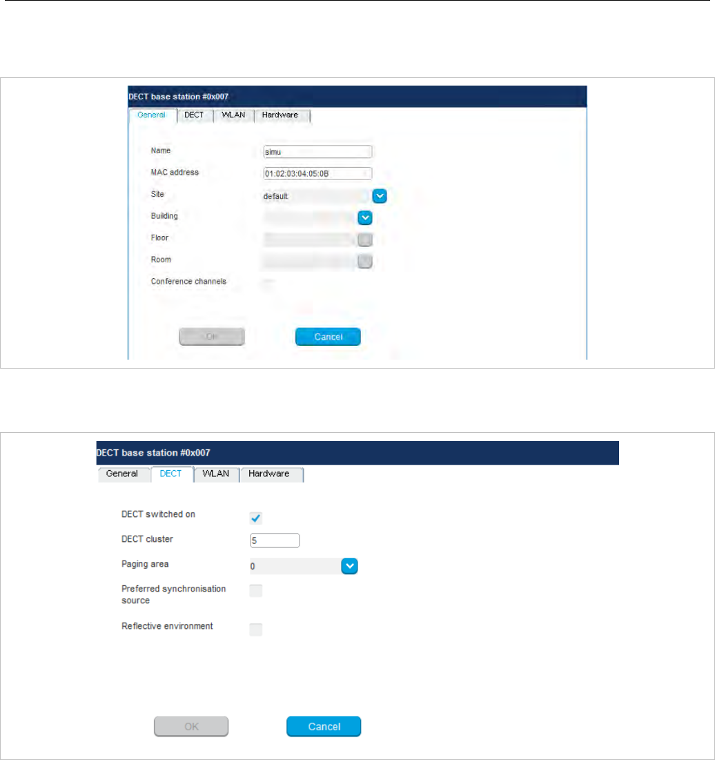
SIP-DECT OM System Manual
164
“General” tab
This tab contains the general DECT base station parameters.
“DECT” tab
This tab contains the DECT base station's DECT parameters.
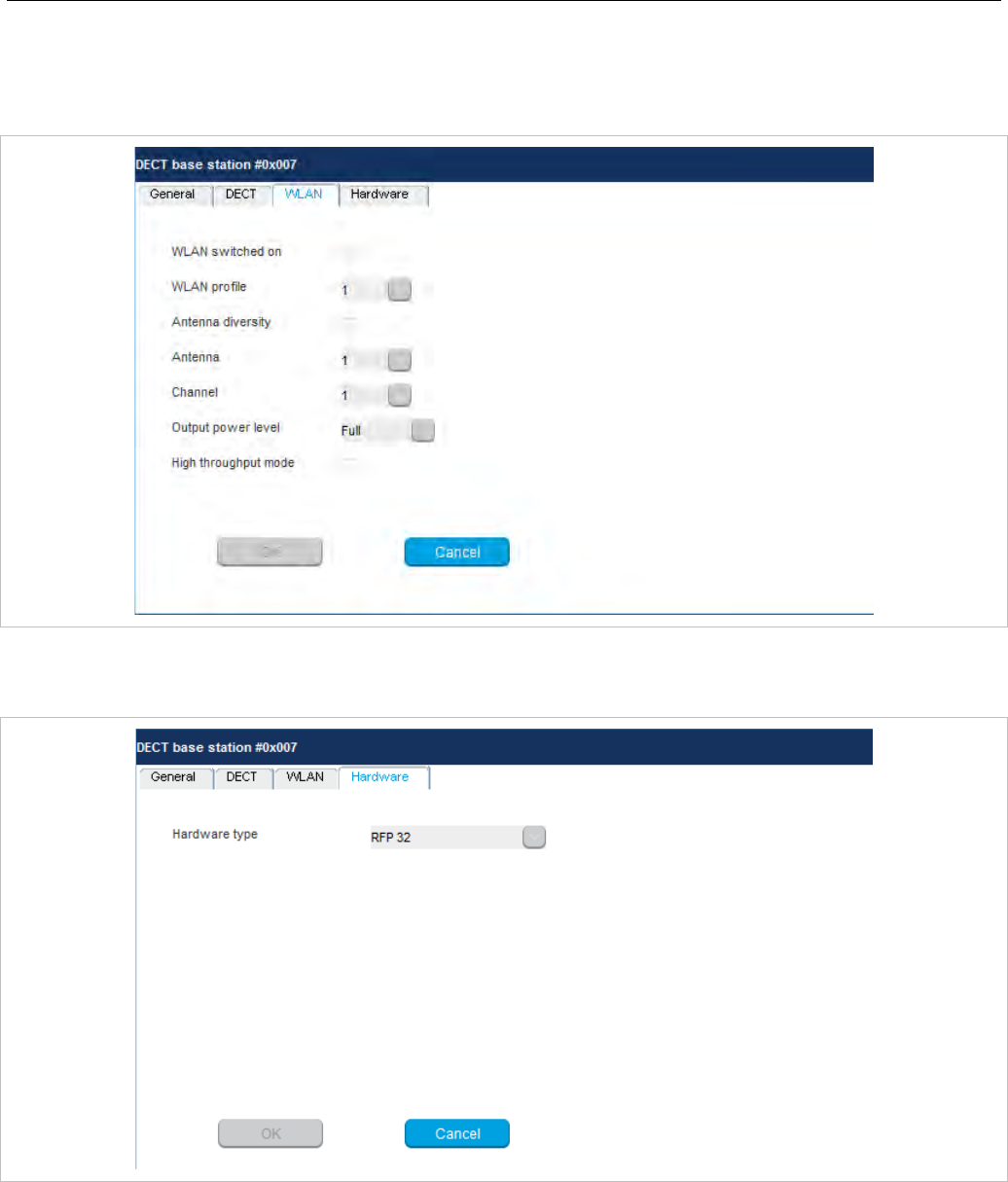
OM Management Portal (OMP)
165
“WLAN” tab
This tab contains the DECT base station's WLAN parameters. Settings in the WLAN tab apply to
RFP 42 WLAN and RFP 43 WLAN base stations only.
“Hardware” tab
In Monitor Mode, this tab shows hardware information of the selected DECT base station.
In configuration mode, the DECT base station Hardware type can be set if it is connecting to the OMM
for the first time. Once the correct hardware type is received from the DECT base station, you cannot
change it.

SIP-DECT OM System Manual
166
6.7.1.2 Adding New DECT Base Stations
You must be in Configuration Mode to add a new DECT base station. To add a DECT base station to
the list of known base stations, do the following:
1 Click Create under the Tasks lists on the right side of the DECT base stations window.
The New radio fixed part panel opens.
2 Configure the DECT base station (see parameter descriptions below).
3 Click OK.
The following parameters can be set in the tabs of the New DECT base station panel:
“General” tab
• Name: The name for the RFP.
• MAC address: Each RFP is identified by its unique MAC address (6 bytes hex format, colon
separated). Enter the MAC address, it can be found on the back of the chassis.
• Site: If several sites exist, select the site the RFP is assigned to.
• Building, Floor, Room: For easier localization of the RFP you can enter data in these fields.
• Conference channels: Activate this option to enable the RFP to provide channels for 3-way
conferencing. This option is available for RFP 35 / 36 / 37 / 43 (see section 7.20.7).
“DECT” tab
• DECT switched on: The DECT functionality for each RFP can be switched on/off.
• DECT cluster: If DECT is active the RFP can be assigned to a cluster.
• Paging area: Enter the paging area, the RFP is assigned to.
Note: The Paging area size is set in the DECT tab of the System
settings menu (see section 6.5.1). The assignment between
RFPs and paging areas can be changed in the Paging areas
menu (see section 6.7.1.8).
• Preferred synchronization source: Activate this checkbox if the RFP should be used as
synchronization source for the other RFPs in the cluster. For background information on RFP
synchronization see section 7.2.
• Reflective environment: Within areas containing lot of reflective surfaces (e.g. metal or metal coated
glass) in an open space environment the voice quality of a DECT call can be disturbed because of
signal reflections which arrive on the DECT phone or RFP using multipath propagation. Calls may
have permanent drop outs while moving and high error rates on the RFPs and DECT phones.
For such environment Mitel has developed the DECT XQ enhancement into base stations
(RFP 32/34 , RFP 42 WLAN and RFP 35/36/37 IP, RFP 43 WLAN) and the Mitel 600 DECT phones
family. Using this enhancement by switching the Reflective environment flag on might reduce drop
outs and cracking noise.
As soon as Reflective environment is switched on, the number of calls on an RFP 32/34 resp.
RFP 42 WLAN or RFP 35/36/37 IP resp. RFP 43 WLAN is reduced to 4 calls at the same time.
Please note: The RFPs and DECT phones use more bandwidth on the Air Interfaces if the
“Reflective environment“ is switched on. Therefore this shall only be used when problems
sourced by metal reflections are detected.

OM Management Portal (OMP)
167
“WLAN” tab
Settings in the WLAN tab apply to RFPs of the type “RFP 42 WLAN” and “RFP 43 WLAN” only. For
details about WLAN configurations please see section 7.18.
Please note: WLAN properties can only be set if the correct hardware type is configured in
the Hardware tab.
• WLAN switched on: The WLAN functionality for an RFP 42 WLAN or an RFP 43 WLAN can be
switched on/off.
• For a description of the other parameters which can be set in the WLAN tab, see the description of
the DECT base stations page of the OMM Web service (see section 5.6.3). The corresponding
parameters can be found there in the WLAN settings section.
Note: Configuration of WLAN profiles is only possible with the OM Web
service, see section 5.8.1.
“Hardware” tab
WLAN properties can only be set if the correct hardware type is configured. This can be done manually
before an RFP connects with the OMM and an automatic detection is possible (Auto setting).
6.7.1.3 Changing DECT base station configuration
Changing RFPs is only possible in configuration mode. To change the configuration of an existing
RFP, do the following:
1 Select the appropriate RFP in the RFP table.
2 Click Configure under the Tasks lists on the right side of the DECT base stations window.
The DECT base station detail panel opens.
3 Change RFP parameters (see descriptions in section 6.7.1.2).
4 Click OK.
6.7.1.4 Viewing DECT base station Details
You can view the configuration of an RFP in Monitor Mode. Proceed as follows:
1 Select the appropriate RFP in the RFP table.
2 Click Show details under the Tasks lists on the right side of the DECT base stations window.
The DECT base station detail panel opens.
3 To close the RFP detail panel, click Cancel.
6.7.1.5 Deleting DECT base stations
Deleting RFPs is only possible in Configuration Mode. To delete an existing RFP, do the following:
1 Select the appropriate RFP(s) in the RFP table by activating the corresponding checkbox(es).
2 Click Delete under the Tasks lists on the right side of the DECT base stations window.
The Delete selected DECT base station(s) dialog opens showing a confirmation prompt.
3 Click OK to confirm.
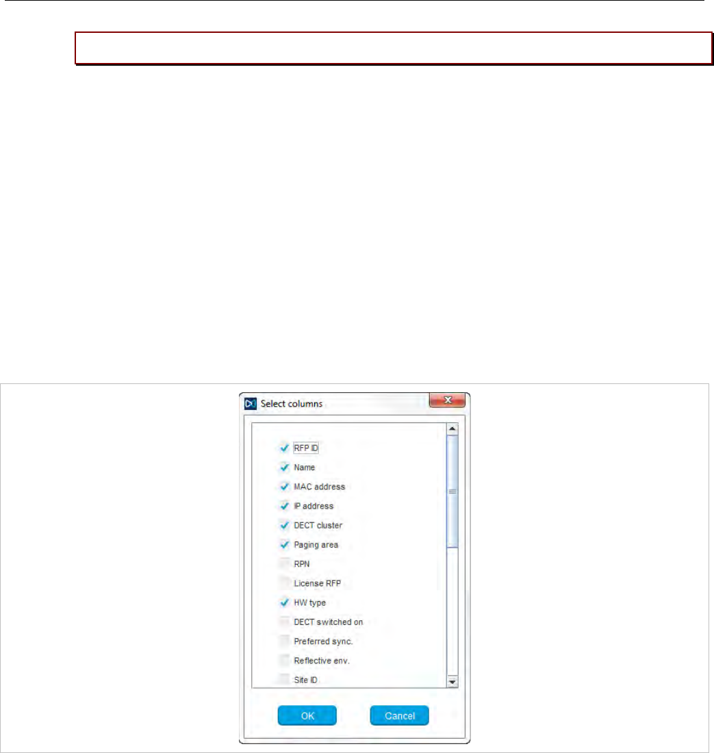
SIP-DECT OM System Manual
168
Please note: License RFPs cannot be deleted.
6.7.1.6 Showing Synchronization Relations
You can view the synchronization relations of a DECT base station in Monitor Mode. Do the following:
1 Select the appropriate RFPs in the RFP table. At least two RFPs must be selected to show their
synchronization relations.
2 Click Show sync. Relations under the Tasks lists on the right side of the DECT base stations
window.
The view switches to the Sync view menu . For further information see section 6.7.6.
6.7.1.7 Selecting Columns
You can adapt the parameters shown in the RFP table to your needs:
1 Click Select columns under the Tasks lists on the right side of the DECT base stations window.
The Select columns dialog opens.
2 Select the columns that shall be shown by activating the appropriate checkboxes.
3 Click the OK button.
The RFP table is updated accordingly.
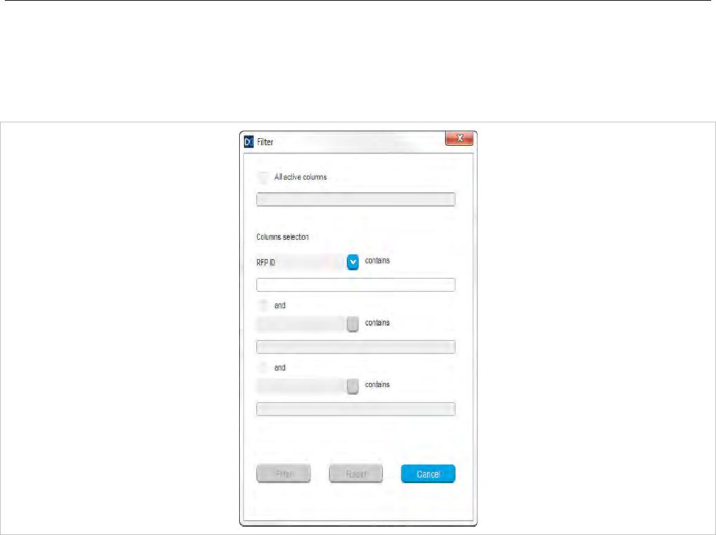
OM Management Portal (OMP)
169
6.7.1.8 Filtering RFP Table
You can filter the list of RFP datasets shown in the RFP table by using a filter.
1 Click Filter under the Tasks lists on the right side of the DECT base stations window.
The Filter dialog opens.
2 Enter the search string that serves as filter criterion. You can enter digits and characters. The search
is case sensitive.
3 Click on the Filter button.
The Filter dialog is closed and the RFP table will be adapted accordingly.
4 To reset the filter, click on the Filter command in the task bar on the right of the DECT base stations
panel.
5 In the Filter dialog click on the Reset button.
6.7.2 “PAGING AREAS” MENU
The Paging area menu shows all configured RFPs in a tree structure consisting of two trees:
• The left Unassigned RFPs tree contains all RFPs without an assigned paging area.
• The right Paging areas tree shows all configured paging areas with RFPs assigned to these paging
areas.
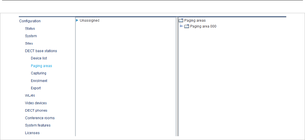
SIP-DECT OM System Manual
170
All RFPs are shown including their site and optional hierarchy (building, floor, and room) settings.
• RFPs can be moved by drag and drop from unassigned tree to paging area tree and vice versa, as
well as between different paging areas inside the paging area tree.
• Only one RFP node can be moved at once.
• If a site or a hierarchy node is selected, all RFPs which are children of this node will be moved.
• If a paging area is completely filled with RFPs, moving additional RFPs in that paging area is
prevented.
• If not all RFPs (selected by a site or hierarchy node) can be moved into a paging area, you will be
asked if you want to move as much as possible RFPs or if the operation shall be cancelled.
Note: The Paging area size is set in the DECT tab of the System
settings menu (see section 6.5.1).
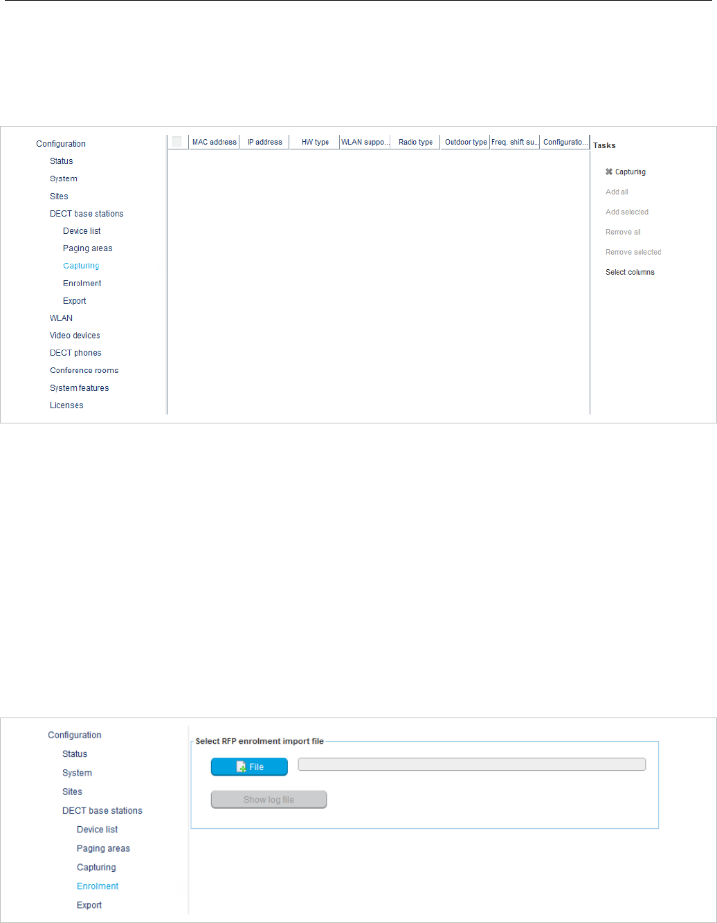
OM Management Portal (OMP)
171
6.7.3 “CAPTURING” MENU
OMP supports the capture of DECT base stations that try to connect to OMM. These RFPs are assigned
to OMM by DHCP options or OMM Configurator settings. Capturing is only accessible in Configuration
Mode.
Available tasks:
• Capturing: Start/stop capturing (active capturing is indicated with a green check mark)
• Add all: Add all captured RFPs to OMM
• Add selected: Add selected RFPs to OMM
• Remove all: Remove selected RFPs from list (without adding to OMM)
• Remove selected: Remove selected RFPs from list (without adding to OMM)
• Select columns: Select RFP capturing table columns to be shown
6.7.4 “ENROLMENT” MENU
The Enrolment menu allows import of RFP datasets using a configuration file. For information about
required configuration file format see section 9.5.
1 Click the File button.
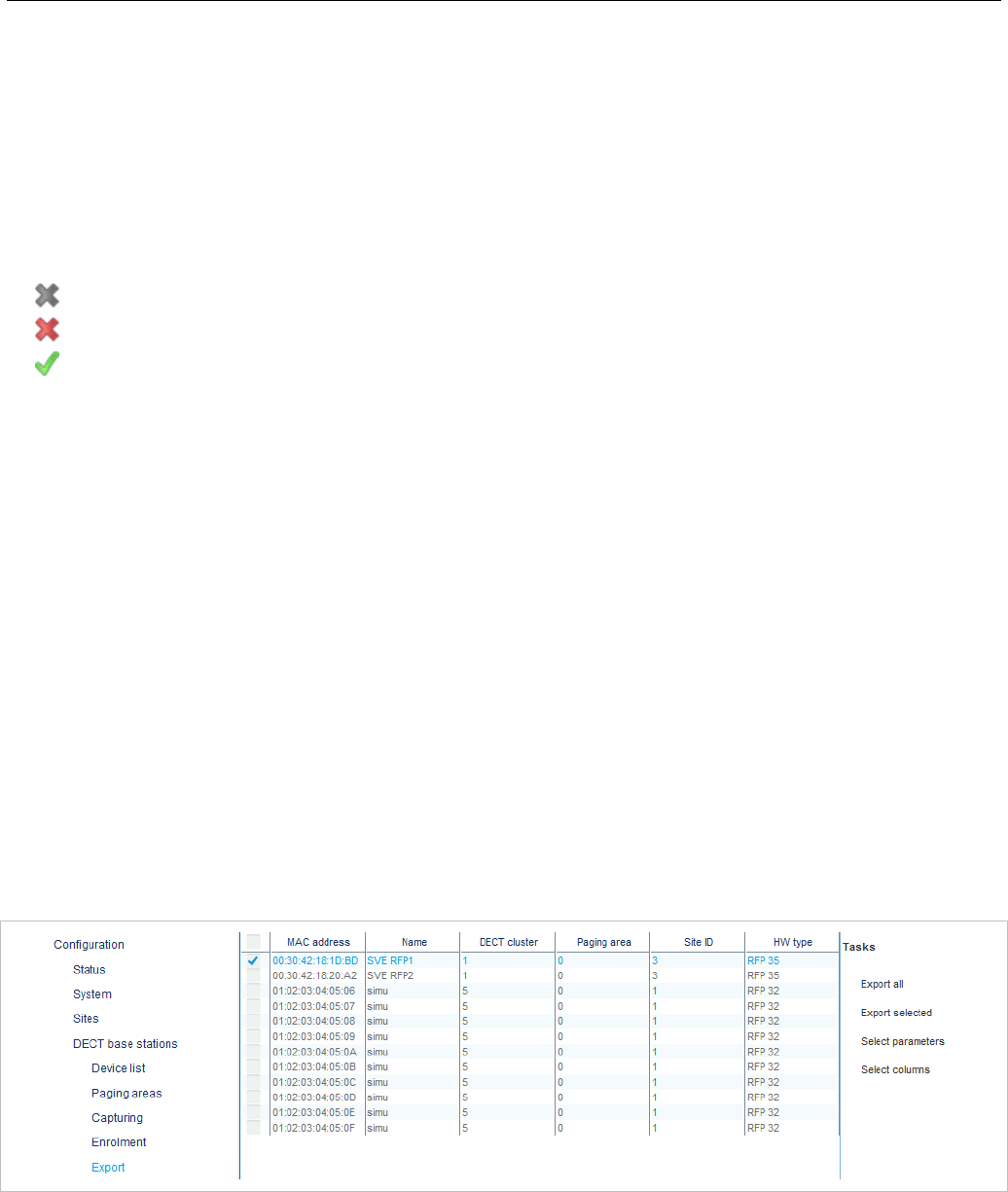
SIP-DECT OM System Manual
172
A file system dialog opens in which you can select the configuration file. The configuration file must be
encoded in UTF-8.
2 To check the results from reading the configuration file press the Show log file button. In case of file
format errors these errors are listed here.
If reading of configuration file is successful, all RFP datasets read are shown in a newly created table.
This table contains, apart from some RFP parameters, the Status column which shows the current
import status for every RFP dataset:
– Not enrolled yet
– Enrolment failed
– OK (Enrolment successful)
3 Start the import by selecting one of the following commands:
Add all: import all RFP datasets into the OMM.
Add selected: import selected RFP datasets to the OMM. For selection activate the corresponding
checkboxes in the RFP table.
Remove all: remove all RFP datasets from table. The table will be hidden.
Remove selected: remove selected RFP datasets from table. If the table is empty after removing of
datasets, the table will be hidden. For selection activate the corresponding checkboxes in the RFP
table.
Show status: show import status of a selected RFP dataset. If enrolment failed for this RFP, a
message describing the enrolment error is shown.
Select columns: select the columns that shall be shown in RFP table (see also 6.7.1.7).
6.7.5 “EXPORT” MENU
The Export menu allows export of all RFPs enrolled to the OMM to a “.csv” file. The generated file can
be viewed with a standard spreadsheet application.
All enrolled DECT base stations are shown in a table.
The following tasks can be performed:
• Export all: export all DECT base station datasets.
• Export selected: export selected DECT base station datasets.
• Select parameters: select DECT base station parameters to be written to the .csv file (select all
DECT base station parameters or a subset of these parameters).
• Select columns: select the columns to be written to the .csv file.
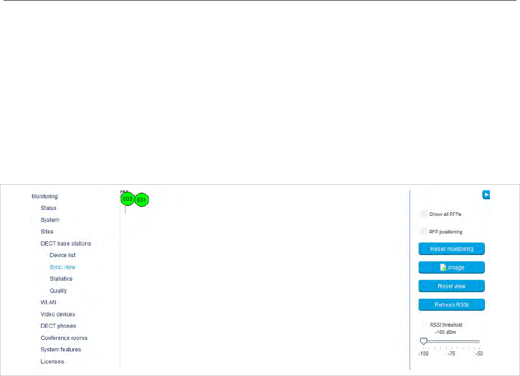
OM Management Portal (OMP)
173
When the export begins, a file system dialog opens where you can select the export file name. If all
parameters are selected for export, the export file can be re-imported using the Enrolment function (see
section 6.7.3). For information about DECT base station export file format see Appendix, section 9.6).
6.7.6 “SYNC VIEW” MENU
The Sync view menu allows verification of the synchronization relations between DECT base stations in
a graphical manner.
Note: For information on DECT base station synchronization, see
section 7.2.
To open the task panel, click the arrow icon in the upper right corner of the Sync view panel.
The task panel is displayed on the right. The following tasks can be performed:
• Show all RFPs: If this checkbox is activated, all configured RFPs are shown in the sync panel; else
only selected RFPs are shown.
• RFP positioning: If this checkbox is activated, RFP positions can be changed; else RFP positions
are fixed.
• Reset monitoring: reset all active sync view monitoring relations.
• Image: select background image for sync panel.
• Reset view: reset selected view (zero coordinates are reset to the left upper corner of the sync view
panel).
• Refresh RSSI: request new RSSI values from OMM for active sync relations.
Viewing sync relations
RFPs for which sync relations shall be shown, can be selected as follows:
• Select (more than one) RFP in device list table (see section 6.7.1)
or
• Activate RFP mouse menu in sync view: Press the right mouse button while mouse cursor is on an
RFP icon and select the Activate Monitoring command from the context menu.
The color of the RFP icon indicates synchronization state of that RFP:
• Grey: inactive
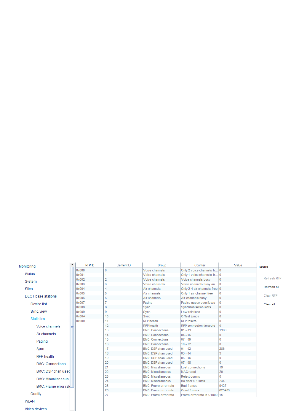
SIP-DECT OM System Manual
174
• Red: not synchronized
• Yellow: searching
• Green: synchronized
Sync relations between RFPs are represented by arrows.
Viewing RSSI values
The color of the arrows between RFPs is an indication of the RSSI value of the link:
• Red: RSSI < -90 dBm
• Orange: -90 dBm <= RSSI <= -70 dBm
• Green: RSSI > -70 dBm
If the mouse is moved over an RFP with monitoring activated, a tool tip with RSSI values will be opened.
You can use the RSSI threshold slider to limit the display of values in the tool tip.
6.7.7 “STATISTICS” MENU
The DECT base stations -> Statistics menu provides information about DECT base station statistics
counters. It contains:
• an overview panel with all statistics counters (see section 6.7.7.1)
• multiple statistics group panels, where related statistics counter types are grouped together (see
section 6.7.7.2).
The menu is only available in Monitor Mode.
6.7.7.1 DECT base station Statistics Overview
The DECT base station statistics overview page contains a list of RFPs by ID, and an overview of all
RFP statistics counters.

OM Management Portal (OMP)
175
The following tasks can be performed:
• Refresh RFP: request counter update by OMM for selected DECT base station statistics counters.
• Refresh all: request counter update by OMM for all DECT base station statistics counters.
• Clear RFP: clear all DECT base station statistics counters on selected DECT base station.
• Clear all: clear all DECT base station statistics counters.
If a DECT base station is selected (left RFP ID table), the statistics counter table shows counter values
for that DECT base station (right table). When a statistics counter entry is selected, a detail panel opens
which shows more detailed information for that counter.
The detail panel shows values for total occurrence and occurrence in current and last week. You can
clear the selected statistics counter on the selected DECT base station by pressing the Clear button.
6.7.7.2 DECT base station Statistics Group Panels
The DECT base station statistics group panels divide DECT base station statistics counters into logical
groups. This allows display of all statistics counters of a special group of all DECT base stations in one
table.
The group panels are listed under the Statistics menu entry in the left panel.
Note that with SIP-DECT 6.0 or later, the statistic data collected by the BMC part of each DECT base
station device (in the DECT MAC layer) are now shown with the DECT base station statistic data
collected by the OMM.
As an update between OMM and DECT base station usually occurs once every hour, it can take up to
one hour for an event that increments a BMC statistic counter to appear in the OMP.
The following tasks can be performed:
• Refresh RFP: request counter update by OMM for selected DECT base station.
• Refresh all: request counter update by OMM for all counters.
• Clear group RFP: clear counter group of selected DECT base stations.
• Clear group: clear counter group of all DECT base stations.
• Clear RFP: clear all counters of selected DECT base station.
• Clear all: clear all counters of all DECT base stations.
6.7.8 “QUALITY” MENU
OMP provides a monitoring ability for critical IP network parameters. Administrators can check basic
network quality information for all DECT base stations. This includes Voice quality (Jitter, Packet lost)
and OMM to RFP link quality (Roundtrip delay).
The menu is only available in Monitor Mode.
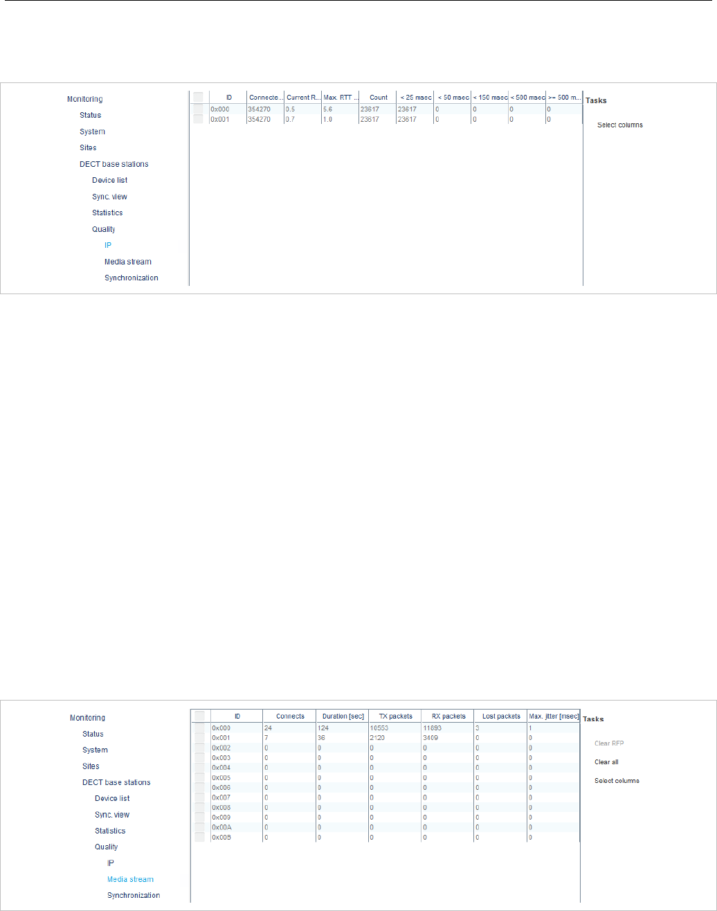
SIP-DECT OM System Manual
176
6.7.8.1 IP
IP quality menu provides information about link quality between DECT base stations and OMM.
Displayed parameters:
• ID: Radio fixed part identifier
• Connected time: Time the RFP is connected to OMM (sec)
• Current RTT: Current roundtrip time between RFP and OMM (msec)
• Max. RTT: Maximal detected roundtrip time between RFP and OMM
• Count: Number of roundtrip time measures
• < 25 msec: Number of roundtrip time measures lower than 25 msec
• < 50 msec: Number of roundtrip time measures between 25 and 50 msec
• < 150 msec: Number of roundtrip time measures between 50 and 150 msec
• < 500 msec: Number of roundtrip time measures between 150 and 500 msec
• >= 500 msec: Number of roundtrip time measures 500 msec and more
Available tasks:
• Select columns: Columns to be shown in IP quality table
6.7.8.2 Media Stream
Media stream panel provides information about voice quality.
Displayed parameters:
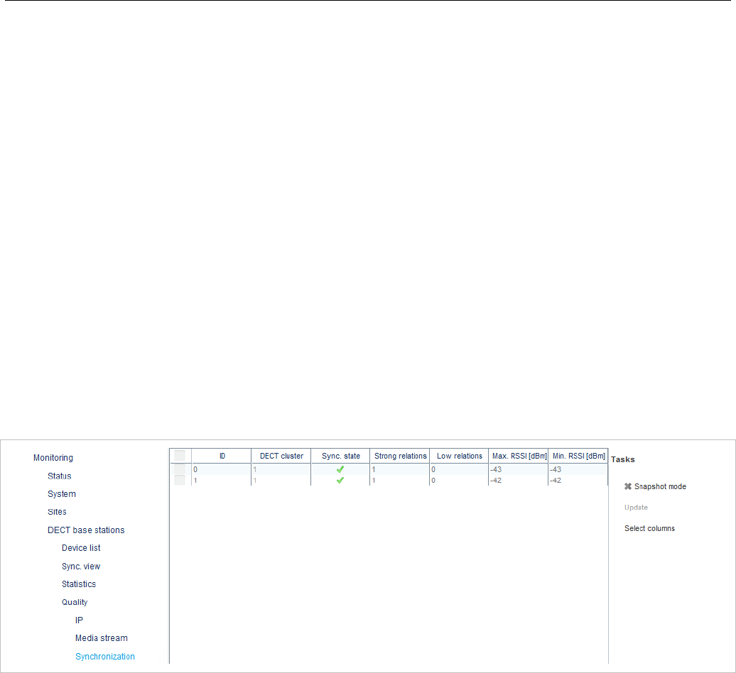
OM Management Portal (OMP)
177
• ID: Radio fixed part identifier
• Connects
• Duration (sec)
• TX packets
• RX packets
• Lost packets
• Max. jitter(msec)
Available tasks:
• Clear RFP: Clear values for selected RFPs
• Clear all: Clear values for all RFPs
• Select columns: Select media stream quality table columns to be shown
6.7.8.3 Synchronization
Synchronization panel allows checking the synchronization status of RFPs which allows identifying RFPs
with bad synchronization coverage.
Synchronization monitoring can optionally be run in snapshoot mode. If this mode is activated, data
update must be triggered by a user otherwise data were updated automatically anytime if new values
arrive from OMM.
Available parameters:
• ID: Radio fixed part id
• DECT cluster: Cluster of the RFP
• Sync state: Synchronization state of the RFP
• Strong relations
• Low relations
• Max. RSSI (dBm)
• Min. RSSI (dBm)
Available tasks in media synchronization quality table:
• Snapshot mode: Enable snapshot mode (green check mark indicates snapshot mode is on)
• Update: Request data update in snapshoot mode
• Select columns: Select synchronization quality table columns to be shown
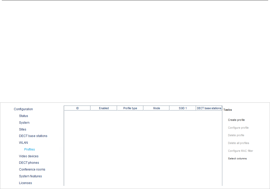
SIP-DECT OM System Manual
178
6.8 “WLAN” MENU
OMP supports configuration of WLAN profiles and provides an overview of wireless clients currently
connected.
6.8.1 PROFILES
OMM supports up to 20 WLAN profiles, which can be added, changed and deleted in OMP configuration
mode. Configuration and state of any WLAN profile can be checked in monitoring mode.
6.8.1.1 WLAN Profiles - configuration mode
WLAN profile configuration menu provides an overview of all configured WLAN profiles.
The following tasks are available in this menu:
• Create profile: Create a new WLAN profile (available if the maximal number of 10 WLAN profiles is
not yet reached)
• Configure profile: Reconfigure selected profile
• Delete profile: Deletes a selected profile (only available if selected profile is not in use by any Radio
fixed part)
• Delete all profiles: Deletes all existing profiles (only available if none of these profiles is in use by
any Radio fixed part)
• Configure MAC filter: Add, configure, delete MAC filter for selected profile
• Select columns: Select WLAN profile table columns to be shown
6.8.1.2 WLAN Profiles Monitoring Mode
WLAN profile monitoring menu shows all configured WLAN profiles.
The following tasks are available:
• Show Profile: Show details of selected WLAN profile
• Show MAC filter: Show configured MAC filter of selected WLAN profile
• Select columns: Select WLAN profile table columns to be shown
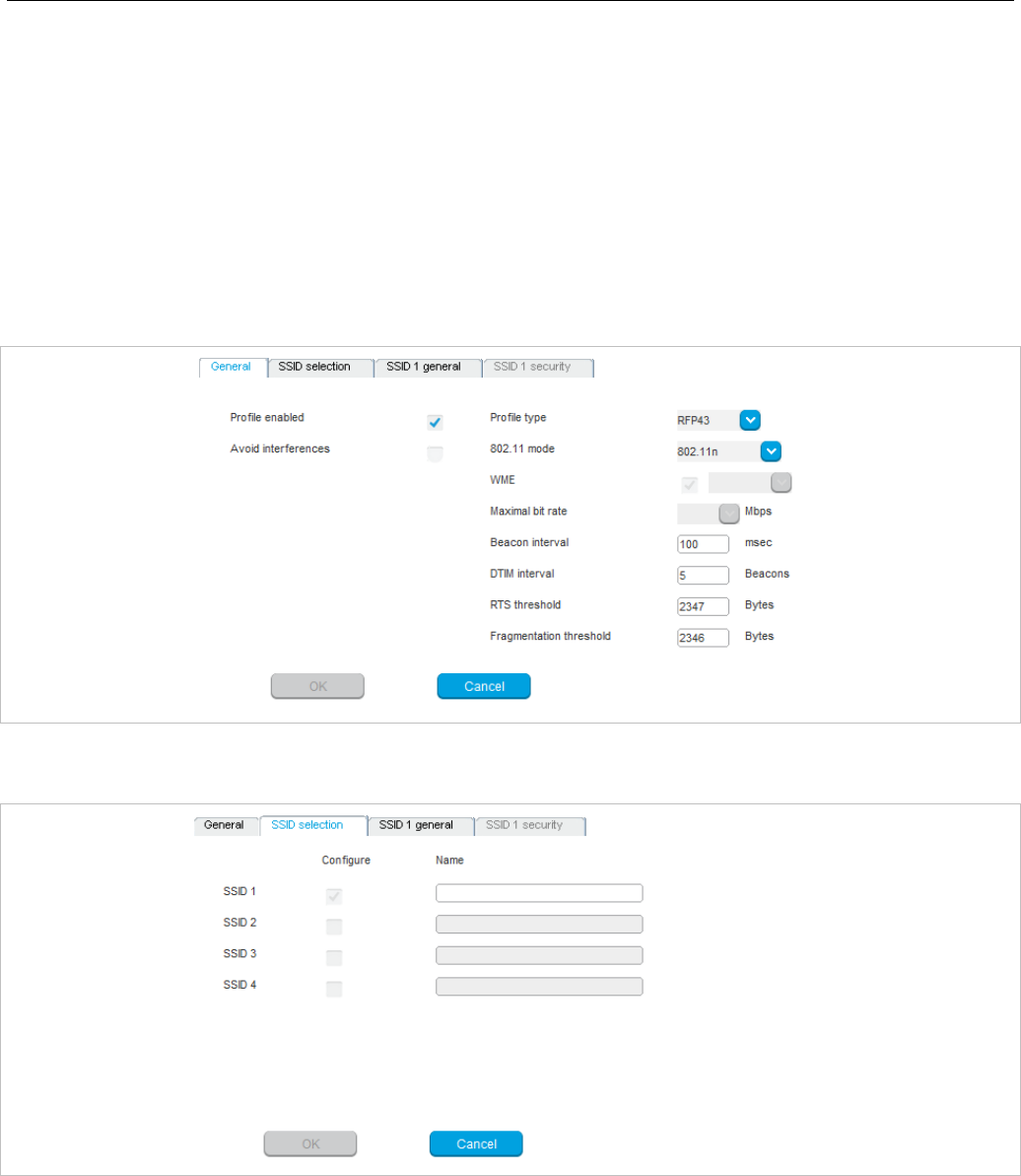
OM Management Portal (OMP)
179
6.8.1.3 WLAN Profile Detail Panel
WLAN profile detail panel is used to create, reconfigure or show a profile. It consists of different tabs
which are used for general settings of WLAN profile, SSID configuration and SSID security settings.
WLAN profile detail panel is opened if one of the following tasks is performed in WLAN profile menu:
• Create profile (configuration mode)
• Configure profile (configuration mode)
• Show profile (monitoring mode)
The “General” tab is always shown and configures/shows general settings of this profile like enabling of
profile and profile type.
The ”SSID selection” tab is used for enabling of SSIDs. At least “SSID 1” is always enabled. “SSID 2”,
“SSID 3” and “SSID 4” can be activated optional.
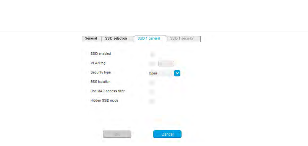
SIP-DECT OM System Manual
180
The “SSID x general” tab is shown for any activated SSID. Among other things, you can use it to select
Security type.
A tab “SSID x security” is shown as well. It is accessible only for SSIDs with security type set to “WEP”
or “WPA”. If security type stays at “Open” this tab is inactive. It allows setting of all necessary security
parameters for this SSID.
6.8.1.4 MAC Access Filter Detail Panel
MAC access filter detail panel in configuration mode allows the adding, configuring and deleting of
MAC access filters. File import and export of MAC access filters is supported as well.
Monitoring mode shows all configured MAC access filters only.
MAC access filter detail panel is opened if one of the following tasks is performed in WLAN profile menu:
• Configure MAC filter (configuration mode)
• Show MAC filter (monitoring mode)
The “General” tab in configuration mode shows all configured MAC access filter.
The following actions are available:
• Create: Create new MAC access filter
• Configure: Change name of selected MAC access filter
• Delete: Delete all selected MAC access filter
The “Import” tab (configuration mode only) provides import of a list of MAC access filter from file.
The “Export” tab (configuration mode only) provides export of all configured MAC access filters to file. If
no MAC access filter is configured, this tab is inactive.
6.8.1.5 Clients
WLAN clients menu which is available in monitoring mode only, shows all currently connected wireless
clients.

OM Management Portal (OMP)
181
6.9 “VIDEO DEVICES” MENU
The Video devices panel lists all configured video devices. The device list is available in Configuration
Mode as well as in Monitor mode.
New video device entries show up automatically after they are connected to and recognized by a DECT
base station. The Plugged and State columns shows the following states:
• / unplugged – Video device is not connected.
• / plugged – Video device is connected.
• / started – Video device is being watched in the OM Locating application.
• / stopped – Video device is connected but disabled in the OMP.
The Tag column shows the USB ID of the connected video device. The USB path column shows the
USB port number to be used, e.g. “1” is a video device connected directly to the RFP while “1.1”
indicates an indirect connection using an USB hub.
The tasks which can be performed are mode-dependant.
Configuration mode Monitor mode See section
Configure: configure selected video device
in detail panel 6.9.1
Show details: show selected video
device in detail panel 6.9.2
Delete: delete selected disconnected video
device 6.9.3
Filter: show only video device entries in
table which contains a special search string
Filter: show only video device
entries in table which contains a
special search string
6.9.4
6.9.1 CHANGING VIDEO DEVICES
Changing video devices is only possible in Configuration Mode. To change the configuration of an
existing video device, do the following:
1 Select the appropriate video device in the video devices table.
2 In the task bar on the right of the Video devices panel click on the Configure command.
The video device detail panel opens.
3 Change video device parameters, see description below.
4 Press the OK button.
Please note: You cannot change the configuration for a video device that is being watched
in the OM Locating application (State column shows “active”). You must disable the video
device first by deactivating the Active option.
The following parameters can be set in the General tab of the Video devices panel:
• Active: Disable this option to switch off the video device. This also switches off the status LED of the
video device immediately (if applicable).
• Name: Enter a meaningful name for the video device.
• Building, Floor, Room: For easier localization of the video device you can enter data in these fields.
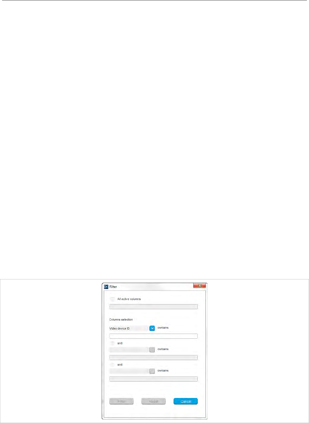
SIP-DECT OM System Manual
182
• Resolution: Select a resolution for the video device. Higher resolutions require more bandwidth when
watching the video image in the OM Locating application. Note, that not all video devices support all
available resolutions. Default: “VGA (640 x 480)”.
• Frame rate: Select a frame rate (2-10 frames per second). Higher frame rates require more
bandwidth when watching the video image in the OM Locating application.
• Rotation: Select the video image rotation (0, 90, 180, or 270 degrees).
6.9.2 VIEWING VIDEO DEVICE DETAILS
You can view the configuration of a video device in monitor mode. Proceed as follows:
1 Select the appropriate video device in the video devices table.
2 In the task bar on the right of the Video devices panel click on the Show details command.
The video device detail panel opens (see 6.9.1).
3 Click Cancel to close the video device detail panel.
6.9.3 DELETING VIDEO DEVICES
Deleting video devices is only possible in Configuration Mode. To delete one or more existing video
devices proceed as follows:
1 Select the appropriate video device(s) in the video devices table by activating the corresponding
checkbox(es). Note that you can only delete disconnected video devices.
2 In the task bar on the right of the Video devices panel click on the Delete command.
The Delete selected video devices(s) dialog opens showing a confirmation prompt.
3 Confirm the displayed prompt with OK.
6.9.4 FILTERING VIDEO DEVICE TABLE
You can filter the list of video device entries shown in the video devices table by using a filter.
1 In the task bar on the right of the Video devices panel click on the Filter command.
The Filter dialog opens.
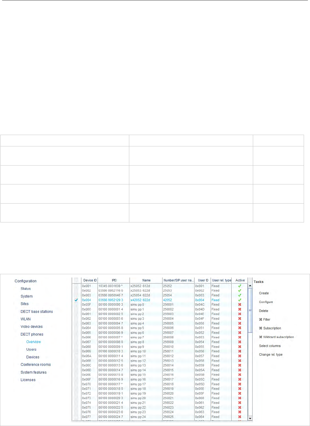
OM Management Portal (OMP)
183
2 Enter the search string that serves as filter criterion. You can enter digits and characters. The search
is case sensitive.
3 Click on the Filter button.
The Filter dialog is closed and the video device table will be adapted accordingly.
4 To reset the filter, click on the Filter command in the task bar on the right of the Video devices panel.
5 In the Filter dialog click on the Reset button.
6.10 “DECT PHONES” MENU
DECT phone datasets can be configured and viewed in the DECT phones menu. The DECT Phones
menu contains different submenus. Each submenu displays its own table of DECT phone datasets.
Configuration mode Monitor mode See section
Overview: Displays all user and device-
related DECT phone data
Overview: Displays all user and device-
related DECT phone data 6.10.1
Users: Displays all DECT phone user
data 6.10.2
Devices: Displays all DECT phone device
data
Devices: Displays all DECT phone
device data 6.10.3
User monitoring: Displays the status of
all monitored users 7.29.7.3
6.10.1 ”OVERVIEW” MENU
In the Overview panel, all user-related and device-related DECT phone data are listed in a table. The
overview is available in Configuration Mode and Monitor mode.
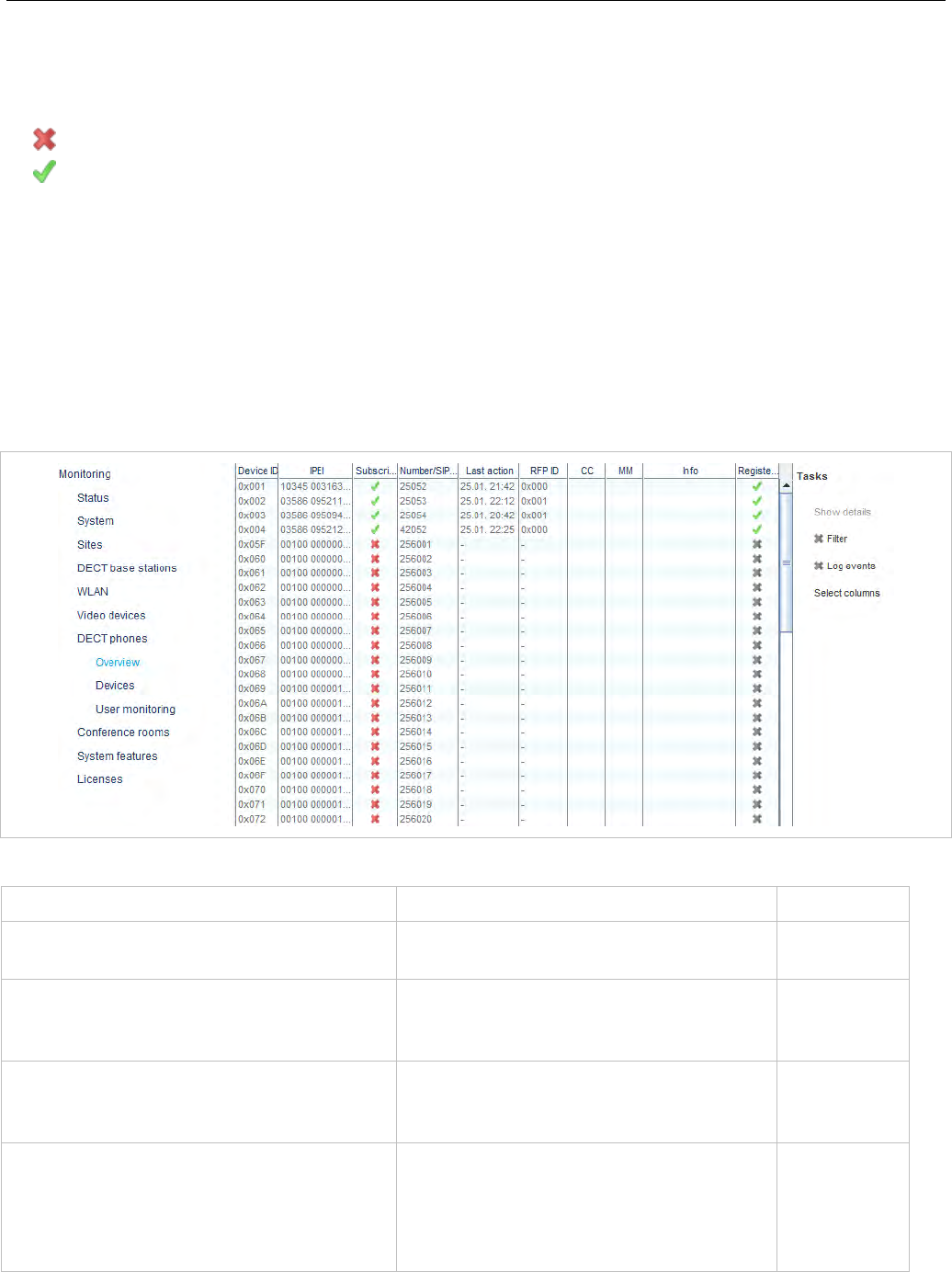
SIP-DECT OM System Manual
184
In Configuration Mode, the Overview panel allows you to create fixed DECT phones (i.e., user and
device are permanently associated).
The Active column shows the following states:
• - DECT phone is not subscribed to the system.
• - DECT phone is subscribed to the system.
Note: If the Active column is not displayed, you can activate it in the
Select columns dialog, see section 6.10.9.
To view the user-device-relation, ensure that the User ID and
Device ID columns are also activated.
In monitor mode you can view the registration status of a DECT phone user by activating the
Registered, Registrar server type, Registrar server and Registrar port columns. See section 6.10.9
for information on selecting columns and section 7.20.6 for information on the SIP registration status.
The tasks you can perform are mode-dependant.
Configuration mode Monitor mode See section
Create: create new fixed DECT phone
dataset in detail panel 6.10.5
Configure: configure selected DECT
phone user and device dataset in detail
panel
6.10.6
Show details: show selected DECT
phone user and device dataset in detail
panel
6.10.4
Delete: delete selected DECT phone user
and device dataset (in case of fixed
relation) or delete DECT phone user and
set device to unbound status (in case of
dynamic relation)
6.10.8
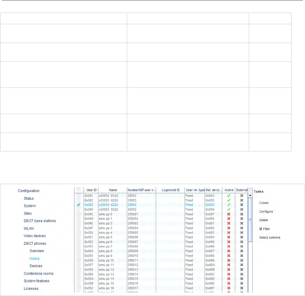
OM Management Portal (OMP)
185
Configuration mode Monitor mode See section
Subscription: start DECT phone
subscription 6.10.7
Wildcard subscription: start DECT
phone wildcard subscription 6.10.7
Select columns: select
columns/parameters to be shown in DECT
phone table
Select columns: select
columns/parameters to be shown in
DECT phone table
6.10.9
Filter: show only DECT phone datasets in
table which contain a special search string
Filter: show only DECT phone datasets
in table which contain a special search
string
6.10.10
Change rel. type: change the DECT
phone relation type 6.10.11
Log events: enable/disable DECT
phone event log 6.10.11
6.10.2 “USERS” MENU
In the Users panel, all DECT phone user data are listed in a table. The Users panel allows you to create
(unbound) users (which should be able to login and logout at a device).
Note: Use the Select columns dialog (see section 6.10.9) to display
the desired DECT phone user data.
The following tasks can be performed:
• Create: create new unbound DECT Phone user dataset (see section 6.10.5).
• Configure: configure selected DECT Phone user dataset (see section 6.10.6).
• Delete: delete selected DECT Phone user dataset. Also delete device data in case of a fixed relation
(see section 6.10.8).
• Select columns: select parameter columns to be shown in table (see section 6.10.9).
• Filter: filter DECT phone datasets shown in table for string set in filter mask (see section 6.10.10).
• Change rel. type: change the DECT phone relation type (see section 6.10.11).
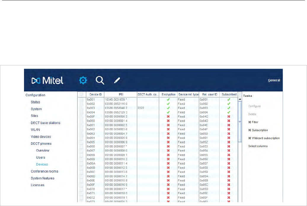
SIP-DECT OM System Manual
186
6.10.3 “DEVICES” MENU
In the Devices panel, all DECT phone device data are listed in a table. The Device panel allows you to
configure the DECT part of a DECT phone device dataset.
Devices cannot be created separately. They are created automatically during subscription (unbound) or
they are created fixed bound to a user when a user is created in the Overview submenu.
Note: Use the Select columns dialog (see section 6.10.9) to display
the desired DECT phone device data.
The following tasks can be performed:
• Configure: configure selected DECT phone device dataset (see section 6.10.6).
• Delete: delete selected DECT phone device dataset (see section 6.10.8).
• Subscription: start DECT phone subscription (see section 6.10.7).
• Wildcard subscription: start DECT phone wildcard subscription (see section 6.10.7).
• Select columns: select parameter columns to be shown in table (see section 6.10.9).
• Filter: filter DECT phone datasets shown in table for string set in filter mask (see section 6.10.10).
6.10.4 DEVICE DETAIL PANEL
The Device detail panel is used for configuration/showing of device settings and creation of new DECT
phone datasets.
To open the Device detail panel
• choose one of the commands in the task bar on the right of the DECT Phones panel (Configure)
or
• double-click on the appropriate device entry in the device table
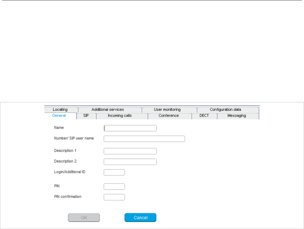
OM Management Portal (OMP)
187
The Device detail panel contains the different parameter groups sorted in tabs. The tabs displayed
depend on the current mode and the panel from which the DECT phone detail panel was invoked.
• Overview panel (configuration and monitor mode): The DECT phone detail panel contains all tabs
listed below.
• User panel (configuration mode): The DECT phone detail panel contains all tabs but not DECT.
• Device panel (configuration mode): The DECT phone detail panel contains only DECT.
6.10.4.1 “General” tab
This tab configures the general settings for the DECT phone dataset.
• Name: represents the DECT phone user name with up to 20 characters
• Number: the DECT phone telephone number with up to 31 characters (1234567890*#azAz+-
_.!$%&/()=?$&). Please be aware that only “*”,”#” and “0” to “9” can be dialed with a DECT phone.
• Description 1 and Description 2: free text comments with up to16 characters each.
• Login/Additional ID: The additional ID can be used as a mean for data search within wildcard
subscription (because of the IPEI is not configured which selects the data otherwise).
• PIN, PIN confirmation: A user PIN to be entered during user login.
Note: The attempt to set the user PIN to an empty string sets the PIN to
the default value “0000”.
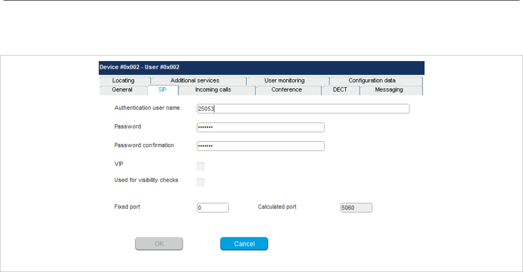
SIP-DECT OM System Manual
188
6.10.4.2 “SIP” tab
This tab configures the SIP authentication for the DECT phone dataset.
• User name: The SIP Authentication user name is optional but recommended. It represents the name
which will be used during SIP registration and authentication. If no name is given the number will be
used by default.
• Password, Password confirmation: The password will be used during SIP registration and
authentication. Enter the appropriate data in these fields.
• VIP: Enable this option if the registration of this user should be prioritized (default off). VIP users will
be registered first. For more information on prioritized registration see section 7.20.5.
• Used for visibility checks: Enables the use of this user account to check the availability of the iPBX
(e.g., in fail over situations). See section 7.20.7 for more information on this feature.
• Fixed port: Specifies the port used explicitly for SIP signaling. If set to 0, an automatically calculated
port is used. The default is 0. See section 3.7 for more information on this feature.
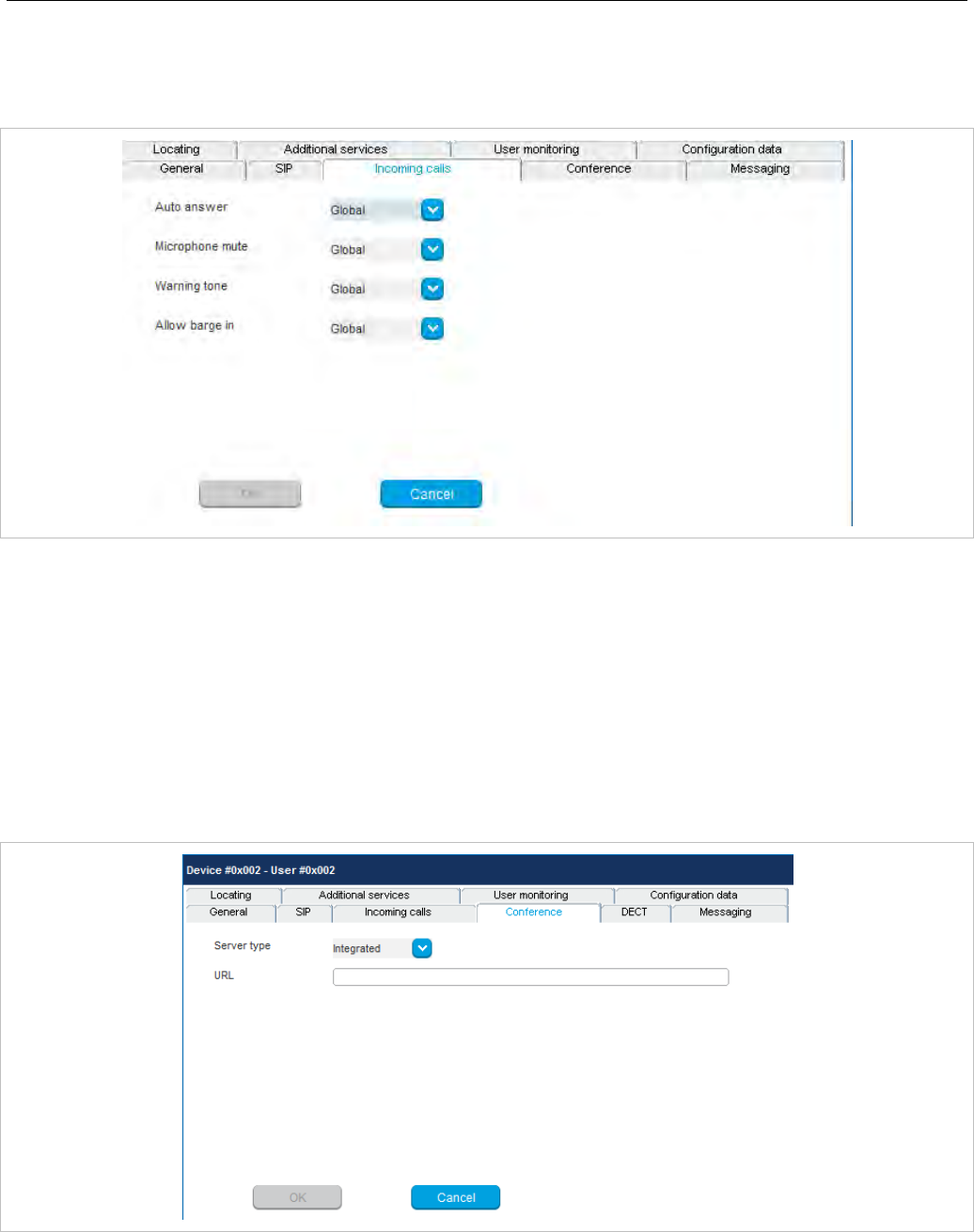
OM Management Portal (OMP)
189
6.10.4.3 ”Incoming calls” tab
This tab allows you to set device-specific settings for auto-answering incoming calls. Default values for
all parameters are inherited from global settings (see section 6.5.4.7).
• Auto answer: Enables or disables auto-answer on incoming calls.
• Microphone mute: Enables or disables microphone muting when incoming calls are automatically
answered.
• Warning tone: Enables or disables warning tone on incoming call. A short ringtone is played if there
are no active calls. If there is an active call in a “barge in” situation, the ringing will be in-band
• Allow barge in: Allows/disallows “barge-in” on existing calls.
6.10.4.4 “Conference” tab
This tab configures the three-way conferencing for the DECT phone dataset individually.
• Server type: Determines the conference service to be used for three-way conferencing. Possible
values are:
- None: Disables 3-way conferencing.
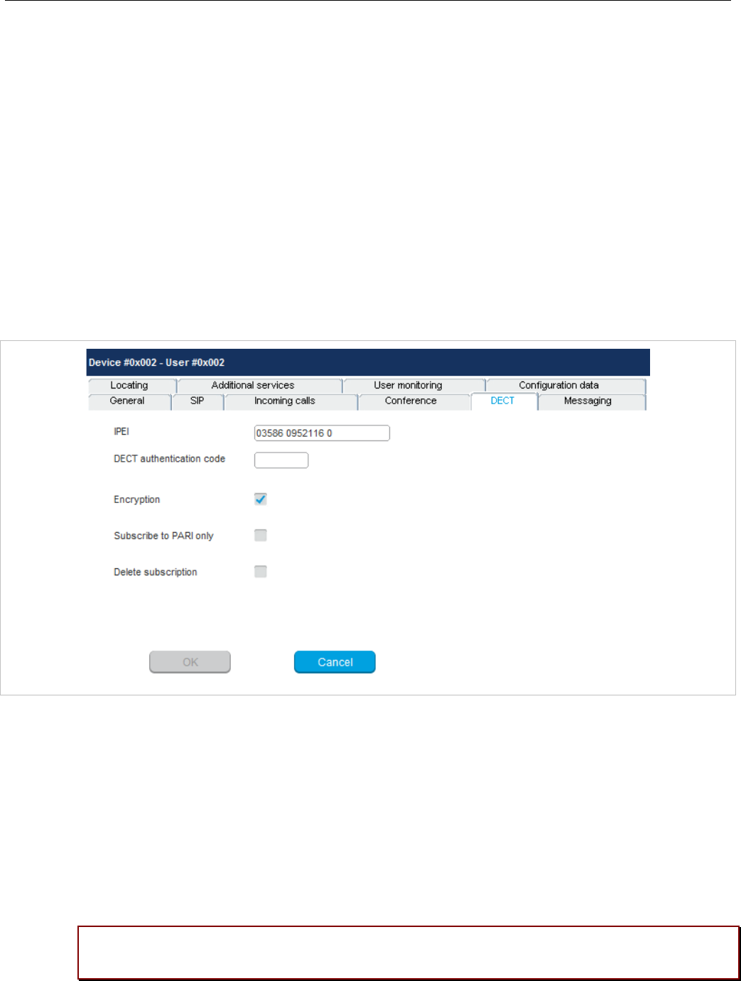
SIP-DECT OM System Manual
190
- Global: The OMM system setting is used (default).
- Integrated: The integrated conference server is used.
- External: An external conference server is used.
- External – Blind Transfer: an external conference server is used (e.g., MiVoice Business). The
initiation of the conference is signaled as a blind transfer to the destination specified in the URL
parameter.
• URL: Address of an external conference server (field only activated if the server type is “External”)
For more information see section 7.20.7.
6.10.4.5 “DECT” tab
This tab configures the DECT part for the DECT phone dataset. When configuring a device (see 6.10.3),
only the DECT tab is shown in the DECT phone detail panel.
• IPEI: This optional setting is the DECT phone IPEI number. On a Mitel DECT 142 / Mitel 142d DECT
phone, the IPEI can be found via the following path of the device menu: Main menu > Phone
settings > System. On a Mitel 600 DECT phone, the IPEI can be found in the System device menu.
Consult the DECT phone’s user guide for further information.
• DECT authentication code: The DECT authentication code is used during initial DECT subscription
as a security option and can be set here for each DECT phone device separately (DECT phone-
specific DECT authentication code). If no DECT phone-specific DECT authentication code is set, the
system-wide DECT authentication code is used.
• Encryption: If the encryption feature is enabled for the whole system (in the System settings menu,
see section 6.5.1), you can de-activate the DECT encryption for this device.
Please note: The DECT phone device must support DECT encryption which is not a
mandatory feature.
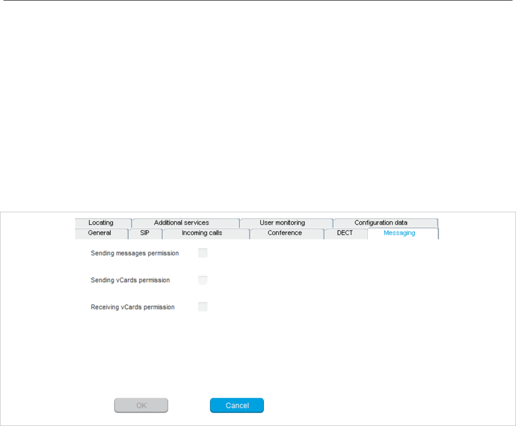
OM Management Portal (OMP)
191
• Subscribe to PARI only: Ensures that the DECT phone subscribes to the PARK code (of a single
OMM, within a Dual Homing installation) and not to the SARI. This option is only available for fixed
user device pairs, and must be set before subscription takes place. For this reason, you should set
the parameter immediately when creating the DECT phone device.
• Delete subscription: This option is only available when configuring an existing DECT phone. If this
option is activated, the subscription data will be deleted which also requires a re-subscription of the
DECT phone device.
6.10.4.6 “Messaging” tab
This tab configures the OM Integrated Messaging and Alerting service for the DECT phone dataset.
If a user is created independent of any specific configuration, the Sending messages and Sending
vCards features are enabled by default.
• Sending messages permission: If this option is enabled, the DECT phone can send messages (if
this function is supported by the device).
Note: For further information see the document SIP-DECT OM
Integrated Messaging & Alerting Application Installation,
Administration & User Guide.
• Sending vCards permission: Allows the user to send personal directory entries as a vCard message
from the DECT phone to other users (if this function is supported by the device).
• Receiving vCards permission: If this option is enabled, all received vCard messages are
automatically processed and written into the personal directory of the DECT phone (if this function is
supported by the device).
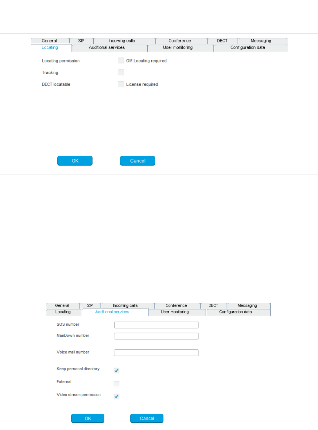
SIP-DECT OM System Manual
192
6.10.4.7 ”Locating” tab
This tab contains parameters for configuring location parameters for the DECT phone.
• Locating permission: This option applies to Mitel 600 DECT phones only. If this option is enabled,
the user is allowed to determine the location of other DECT phones. The main menu of the Mitel 600
DECT phones provides an extra Locating menu entry for this function.
• Tracking: If this option is enabled, the operator of the OM Locating application is able to use the
constant tracking feature for the DECT phone. Note that this feature consumes more of the DECT
phone’s battery power, because it activates a DECT base station update if the device roams and is
not in communication. You also cannot enable this feature, if the DECT locatable option is disabled
• DECT locatable: If this option is enabled, the DECT phone is locatable. Either with the OM Locating
application or by querying it’s location from other DECT phones.
6.10.4.8 “Additional services” tab
This tab configures extra configuration items for the DECT phone dataset.

OM Management Portal (OMP)
193
• SOS number: User-specific SOS number that is dialed automatically if the SOS key on the DECT
phone is pressed.
• ManDown number: User specific “Man down” number that is dialed automatically if a Man down
event happens. This event is triggered by the sensor of a Mitel 600 DECT phone.
If no individual SOS or Man down number is configured for a DECT phone, the number of the
appropriate alarm trigger will be used as calling number in case of a SOS or Man down event. Please
see /31/ for details.
• Voice mail number: The number that will be automatically called as soon as a voice mail call is
initiated on the Mitel 600 DECT phone. If there is no individual voice mail number configured in this
field, then the system-wide voice mail number is used (see also the System setting menu, section
6.5.1). If there is no voice mail number configured (neither the individual nor the system-wide) or
another DECT phone type is used, then the voice mail number must be configured locally in the
DECT phone.
• Keep personal directory: Activate this option, to keep the personal directory data in the DECT
phone if the user logs out.
• External: A user data set can either be provisioned on an external user data server or locally in the
OMM database. To provide an easy way to change the provisioning storage of user data sets, the
user data sets can be moved from an external user data server into the local OMM database and vice
versa.
Deactivate the External option if you want to move user data sets from an external user data server
into the local OMM database.
External to internal transformation rules: To change a user data set from an external user data
server to an internally provisioned one, the following conditions must be applied to the data set:
– external provisioned on an external user data server
– user data set device relation must not be “fixed”
Internal to external transformation rules: To change a user data set from local OMM database to
an external user data server provisioned one the following conditions must be applied for the data set:
– external provisioned on an external server
– user data set device relation must not be “fixed”
– an external user data server must be available
• Video stream permission: Activate this option to allow video streaming on the DECT phone. See
section 7.28 for details on this feature.
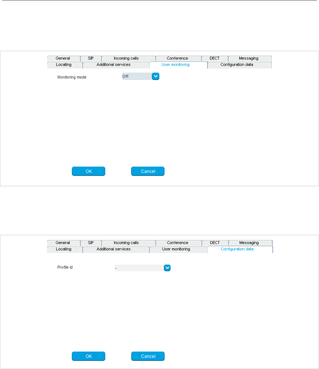
SIP-DECT OM System Manual
194
6.10.4.9 “User monitoring” tab
This tab is designed to configure the user-specific parameters for the User Monitoring feature. For a
description of the parameters which can be set in the User monitoring tab, see the description in
section 7.29.7.2.
6.10.4.10 “Configuration data” tab
The Configuration data tab allows you to assign a Configuration over Air (CoA) profile to a DECT
phone user. See section 7.23 for more information on this feature.
• Profile id: Specifies the CoA configuration profile you want to assign to the DECT phone user.

OM Management Portal (OMP)
195
6.10.5 CREATING DECT PHONE DATASETS
Creating DECT phone datasets is only possible in Configuration Mode. You can create the fixed DECT
phone dataset or only the DECT phone user data.
To create a DECT phone dataset proceed as follows:
1 Click Create under the Task list on the right-hand side of the DECT Phones window.
– In the Overview submenu you can create a fixed DECT phone dataset (with combined user and
device data).
– In the Users submenu you can create an unbound user. This user can login and logout at any
prepared device.
The DECT phone detail panel opens. It provides various tabs where the DECT phone data must be
entered.
2 Configure the DECT phone, see parameter description in section 6.10.4.
3 Press the OK button.
6.10.6 CONFIGURING DECT PHONE DATASETS
Configuring DECT phone datasets is only possible in Configuration Mode. To configure an existing
DECT phone dataset proceed as follows:
1 Select a DECT Phone from the table, and click Configure under the Task list on the right-hand side
of the DECT Phones window.
– In the Overview submenu you can configure the whole DECT phone dataset (user and device
data).
– In the Users submenu you can configure the DECT phone user data.
– In the Device submenu you can configure the DECT phone device data.
The DECT phone detail panel opens.
2 Change the DECT phone dataset as desired, see parameter description in section 6.10.4.
3 Press the OK button.
6.10.7 SUBSCRIBING DECT PHONE DATASETS
After adding a DECT phone dataset to the OMM, the DECT phone must be subscribed. The OMM must
first be enabled to allow subscriptions from DECT phones. Subscribing DECT phone datasets is possible
in the Overview panel and in the Device panel. To start subscription, press one of the following
commands in the DECT phones menu:
• Subscription: start DECT phone subscription with configured IPEI. For more information on this see
section 5.7.3.1.
• Wildcard subscription: start DECT phone wildcard subscription (without configured IPEI). In the
Wildcard subscription dialog, which is now opened, enter the Timeout for this subscription method.
Press the Start button. For more information on this see section 5.7.3.2.

SIP-DECT OM System Manual
196
6.10.8 DELETING DECT PHONE DATASETS
Deleting DECT phone datasets is only possible in configuration mode. You can delete the fixed DECT
phone dataset (in case of fixed relation) or only the DECT phone user data resp. the DECT phone device
data (in case of dynamic relation).
To delete one or more existing DECT phone datasets proceed as follows:
1 Select the appropriate DECT phone dataset(s) in the DECT phone table by activating the
corresponding checkbox(es).
2 In the task bar on the right of the DECT phones panel click on the Delete command.
– In the Overview submenu the whole DECT phone dataset will be deleted.
– In the Users submenu only the DECT phone user data will be deleted.
– In the Devices submenu only the DECT phone device data will be deleted.
The Delete [xxx] dialog opens showing a confirmation prompt.
3 Confirm the displayed prompt with OK.
6.10.9 SELECTING COLUMNS
You can adapt the parameters shown in the DECT phone table to your needs:
1 Click Select columns under the Task list on the right-hand side of the DECT Phones window.
The Select columns dialog opens.
2 Select the columns that shall be shown by activating the appropriate checkboxes.
3 Click the OK button.
4 The DECT phone table will be adapted accordingly.
6.10.10 FILTERING DECT PHONE TABLE
You can filter the list of DECT phone datasets shown in the DECT phone table by using a filter.
1 Click Filter under the Task list on the right-hand side of the DECT Phones window.
The Filter dialog opens.
2 Enter the search string that serves as filter criterion. You can enter digits and characters. The search
is case sensitive.
3 Click on the Filter button.
The Filter dialog is closed and the DECT phone table will be adapted accordingly.
4 To reset the filter, click on the Filter command in the task bar on the right of the DECT phones panel.
5 In the Filter dialog click on the Reset button.

OM Management Portal (OMP)
197
6.10.11 CHANGING THE RELATION TYPE
The user data device relation transformation can only be performed by the admin user. A user data
device relation data set can be changed from “fixed” to “dynamic” and vice versa. This means the
login/logout feature can be enabled or disabled for a DECT phone.
To change the relation type of a DECT phone:
1 Select the appropriate DECT phone dataset(s) in the DECT phone table by activating the
corresponding checkbox(es).
2 Click Change rel. type under the Task list on the right-hand side of the DECT Phones window.
Rules to change the relation from “fixed” to “dynamic”
• The DECT phone must be subscribed.
• A user login/logout PIN is configured in the user data set.
• Depending on the DECT phone user login type (“LoginID”), in the DECT tab of the System settings
menu, the Login ID option must be set in the DECT phone user login type field.
IMPORTANT : If there is no specific PIN configured then “0000” is automatically set.
Rules to change the relation from “dynamic” to “fixed”
• The user relation type must be “Dynamic” (not “Unbound”), because a subscribed DECT phone exists
in this case.
• The user data set is not retrieved from an external user data server / the user data set is provisioned
locally in the OMM database (see also page 193).
6.10.12 ENABLING / DISABLING DECT PHONE EVENT LOG
You can store a DECT phone event log file in Monitor Mode. Do the following:
1 To enable/disable the DECT phone event log, click Log events under the Task list on the right-hand
side of the DECT Phones window:
- DECT phone event log is enabled.
- DECT phone event log is disabled.
2 Repeat step 1 to disable/enable the DECT phone event log.
The DECT phone event log will be stored in a file called “pp_event.log“. This file can be found in the
user’s home directory:
• on a Linux system it is located under ‘~/.oamp’,
• on a windows system under ‘c:/Users/<user>/MyDocuments/.Oamp’.

SIP-DECT OM System Manual
198
6.10.13 USER MONITORING
User monitoring menu available in monitoring mode only a list of the DECT Phone users who are
configured for user monitoring.
The following parameters are displayed for each DECT Phone user:
• User ID
• Name
• Number
• Related device ID
• Mode: User monitoring mode (active or passive)
• Combined User Status (CUS)
• Handset Assignment Status (HAS) (Dynamic User logged on)
• Handset Subscription Status (HSS) (DECT subscribed)
• Handset registration status (HRS) (DECT attached)
• Handset activity status (HCS) (Handset active within time period)
• SIP user registration status (SRS) (SIP user registered)
• Silent charging status (SCS) (Silent charging + Charger)
• Call diversion status (CDS) (immediate call diversion enabled)
• Handset battery status (HBS) (Battery power above limit, warn only)
• Software status (SWS) (minimal required software version, warn only)
Monitoring parameter can have these values:
• - Available
• - Warning
• - Unavailable
• - Escalated
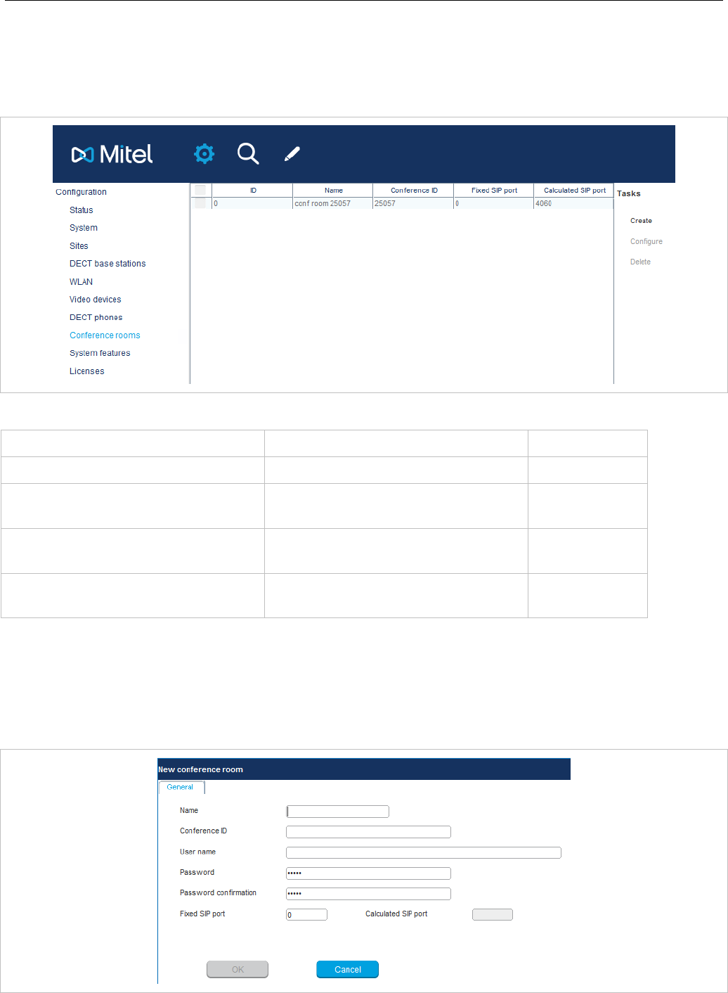
OM Management Portal (OMP)
199
6.11 “CONFERENCE ROOMS” MENU
On this menu page you managed individual conference rooms for the Integrated Conference Server
(ICS). For details on how to configure the conferencing feature refer to section 7.20.7.
The tasks which can be performed are mode-dependant.
Configuration mode Monitor mode See section
Create: create conference room 6.11.1
Configure: configure selected
conference room 6.11.2
Show details: show details about a
selected conference room 6.11.4
Delete: delete selected conference
room 6.11.3
6.11.1 CREATING CONFERENCE ROOMS
In Configuration Mode you can create new conference rooms. Conference rooms will be registered on
the configured SIP registrar, thus you must enter the SIP account data to be used.

SIP-DECT OM System Manual
200
1 Click Create in the Tasks menu of the Conference rooms page.
2 In the General tab, enter the conference room parameters.
- Name: Enter the SIP display name for the SIP account to be used.
- Conference ID: Enter the SIP user id.
- User name: Enter the SIP authentication name.
- Password, Password confirmation: Enter the password that is required by the SIP server.
- Fixed SIP port: Enter the port used explicitly for SIP signaling. If set to 0, an automatically
calculated port is used for this conference room. The default is 0. See section 3.7 for more
information on this feature.
3 Click OK.
6.11.2 CONFIGURING CONFERENCE ROOMS
In Configuration Mode you can configure an existing conference room.
1 Select the appropriate conference room entry in the conference rooms table.
2 Click Configure.
The General tab is displayed showing the current conference room configuration.
3 Change the conference room parameters as required.
4 Click OK.
6.11.3 DELETING CONFERENCE ROOMS
In Configuration Mode, you can delete conference rooms.
1 Select one or more conference rooms entries in the conference rooms table.
2 Click Delete.
A confirmation dialog appears.
3 Click OK to confirm.
6.11.4 VIEWING CONFERENCE ROOM DETAILS
In Monitor Mode, you can view the details of a conference room.
1 Select the appropriate conference room entry in the conference room table.
2 Click Show details.
The General tab is displayed showing the conference room configuration.
3 Click Cancel to close the tab.
6.12 “SYSTEM FEATURES” MENU
The System features menu provides the following entries:
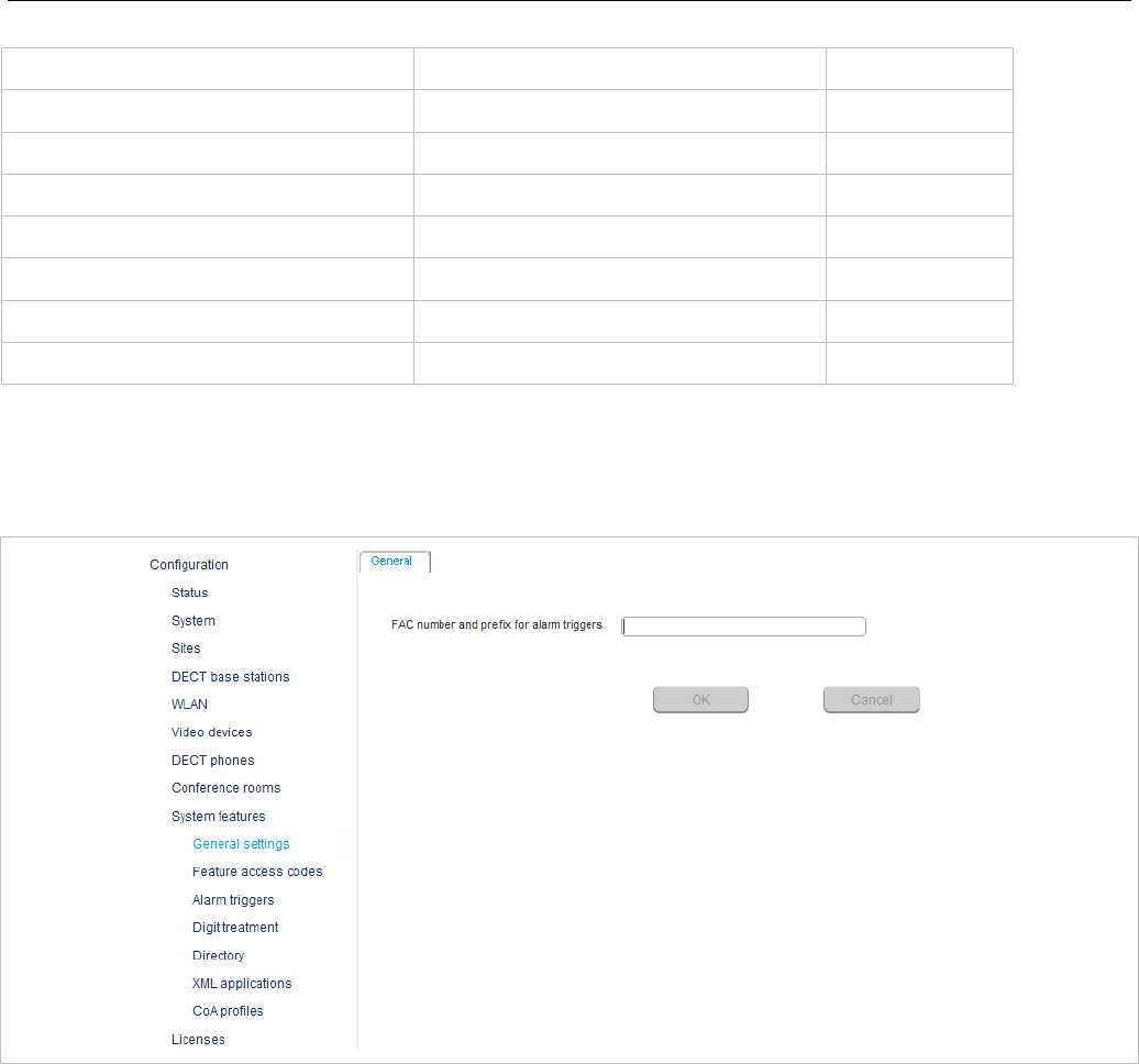
OM Management Portal (OMP)
201
Configuration mode Monitor mode See section
General settings General settings 6.12.1
Feature access codes Feature access codes 6.12.2
Alarm triggers Alarm triggers 6.12.3
Digit treatment Digit treatment 6.12.4
Directory Directory 6.12.5.1
XML applications XML applications 6.12.6
CoA profiles CoA profiles 6.12.7
6.12.1 “GENERAL SETTINGS” MENU
The General settings menu allows to configure/view the FAC number prefix used for feature access
codes and alarm triggers.
1 FAC number and prefix for alarm triggers: Enter a unique FAC number.
2 Press the OK button.
6.12.2 “FEATURE ACCESS CODES” MENU
The Feature access codes menu is used to configure/view the feature access codes parameters.
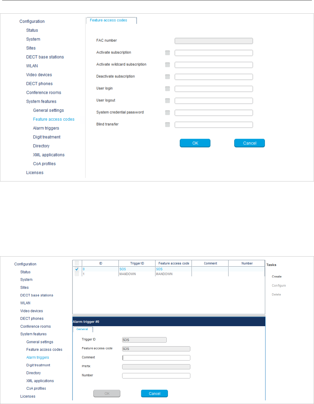
SIP-DECT OM System Manual
202
The FAC number which introduces the feature access code (see also section 6.12.1) is displayed. For a
description of the parameters which can be set in this menu see section 5.9.3.
6.12.3 “ALARM TRIGGERS” MENU
The Alarm triggers menu allows configuration and display of numerous alarm trigger datasets. There
are two predefined alarm triggers (“SOS” and “MANDOWN”) which cannot be deleted.
The tasks which can be performed are mode-dependant.
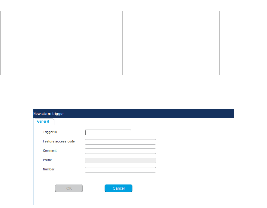
OM Management Portal (OMP)
203
Configuration mode Monitor mode See section
Create: create alarm trigger 6.12.3.1
Configure: configure a selected alarm trigger 6.12.3.2
Show details: show parameters of a
selected alarm trigger 6.12.3.4
Delete: delete selected alarm triggers
6.12.3.3
6.12.3.1 Creating “Alarm triggers”
In Configuration Mode you can create new alarm triggers.
1 Click Create. In the General tab enter the alarm trigger parameters.
2 Trigger ID: Enter the AlarmTrigger ID that the OMM sends to identify the alarm scenario and the
source that triggers the alarm.
3 Feature access code: Enter the feature access code that the user dials to initiate the alarm.
4 Comment: Enter a comment for the new trigger.
5 Prefix: This field displays the FAC number which introduces the feature access code (see also
section 6.12.1).
6 Number: Enter the number to be called if the user triggers the alarm by dialing the feature access
code. If no number is specified, the call is released.
7 Press the OK button.
6.12.3.2 Configuring “Alarm triggers”
In Configuration Mode you can configure an existing alarm trigger.
1 In the alarm trigger table click on the appropriate trigger entry.
2 Click Configure.
The General tab is displayed showing the current trigger configuration.
3 Change the trigger parameters.
4 Press the OK button.
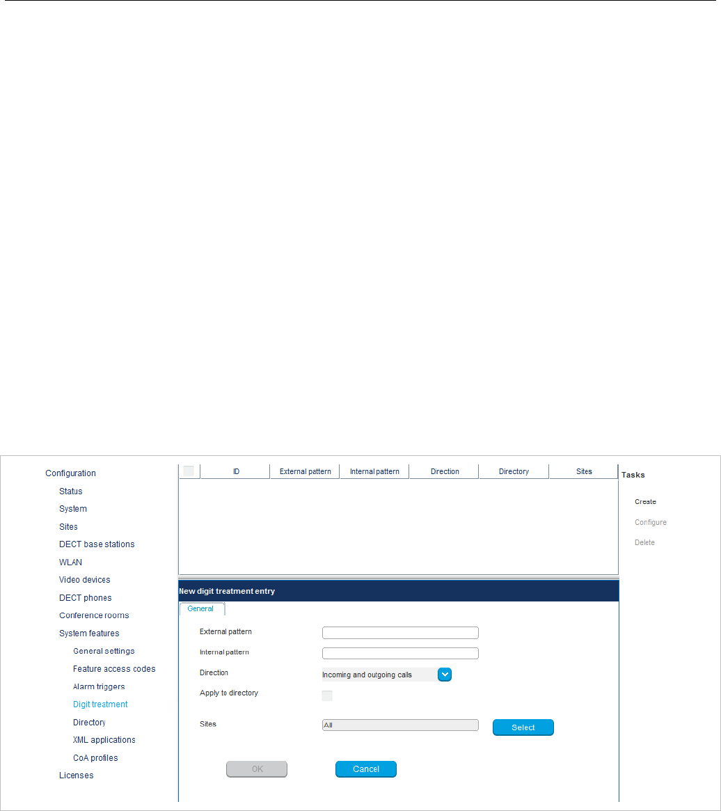
SIP-DECT OM System Manual
204
6.12.3.3 Deleting “Alarm triggers”
In Configuration mode you can delete alarm triggers. The predefined alarm triggers (‘SOS and ’Man
down‘) cannot be deleted.
1 In the alarm trigger table click on one or more trigger entries.
2 Click Delete.
3 Confirm the displayed prompt with OK.
6.12.3.4 View “Alarm trigger” Details
In Monitor Mode you can view the details of an alarm trigger.
1 In the alarm trigger table click on the appropriate trigger entry.
2 Click Show details.
The General tab is displayed showing the trigger configuration.
3 Click Cancel to close the tab.
6.12.4 “DIGIT TREATMENT” MENU
The Digit treatment menu allows you to configure the number manipulation that is provided by the digit
treatment feature for LDAP corporate directories.
For a description of tasks and parameters available in this menu, refer to section 5.9.1.
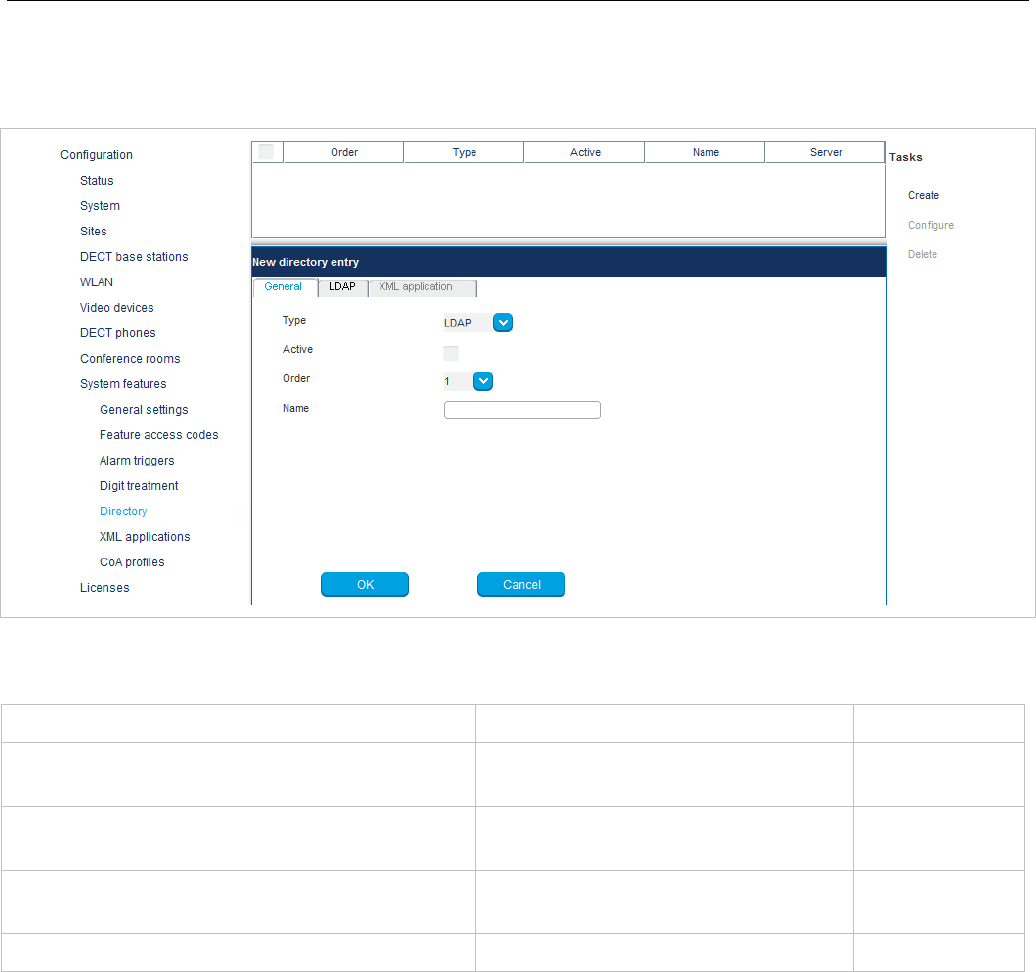
OM Management Portal (OMP)
205
6.12.5 “DIRECTORY” MENU
The Directory menu allows configuration of LDAP or XML-based corporate directory services.
The tasks which can be performed are mode-dependant.
Configuration mode Monitor mode See section
Create: create new directory entry in detail
panel 6.12.5.1
Configure: configure selected directory entry
in detail panel 6.12.5.2
Show details: show selected
directory entry in detail panel 6.12.5.3
Delete: delete selected directory entry/entries 6.12.5.4
6.12.5.1 Creating New Directory Entries
Adding directory entries is only possible in configuration mode. You can configure up to 5 directory
entries. To add a new entry, do the following:
1 In the Tasks bar, click Create.
The New directory entry panel opens and provides various tabs where the directory data must be
entered.
2 Configure the Directory entry (see parameter descriptions below).
3 Click OK.

SIP-DECT OM System Manual
206
The following parameters can be set in the tabs of the New directory entry panel:
General
• Type: Select the protocol that is supported by the directory server (LDAP or XML).
• Active: Enable or disable the entry.
• Order: This setting determines the position in the DECT phone menu (1 – top; 5 – bottom).
• Name: Enter a name for the directory entry. Latin-1 character set is supported.
SIP-DECT 6.0 and later supports the “SIPProxy” placeholder for a directory entry name, in place of
the current primary, secondary or tertiary SIP server address.
Note: The name configured here is not relevant and ignored when the
DECT phone user searches for a call number in the telephone’s
central directory if there is only one directory entry configured.
LDAP
This tab is automatically activated if you have selected the LDAP directory type in the General tab.
• Search base: The search base must be edited (e.g. “ou=people,o=my com”).
The configuration is valid for all DECT phones which support the LDAP directory feature. To make
search requests unique for different users the search base configuration can include placeholders
which are replaced by user specific values when submitting the LDAP request to a server. The
following placeholders are defined:
“<TEL>” which is replaced by the specific telephone number of the user
“<DESC1>” which is replaced by the “Description 1” attribute value of the user
“<DESC2>” which is replaced by the “Description 2” attribute value of the user
• Search type: Searches will be done for one of the following attributes:
– Name (sn) // Surname (default)
– First name (Given name)
• Display type: Selection between the following two alternatives is possible:
– Surname (sn), first name (given name) (default)
– first name (Given name) and Surname (sn)
• Server: (mandatory): Enter the name or IP address of the directory server.
• Port (mandatory): Enter the server port number (default: 389).
Note: SSL (default port 689) is not supported.
Windows® Active Directory Server uses port 3268.
• User name, Password, Password confirmation: User name (a distinguished name) and password
may be filled if requested by the directory server. Otherwise an anonymous bind takes place.
Note: SIP-DECT supports LDAP simple bind.
• Server search timeout: The search results will be accepted within the entered search time (value
range: 1 - 99 sec).
XML application
This tab is automatically activated if you have selected the XML directory type in the General tab.
• Protocol: Select the preferred transfer protocol.

OM Management Portal (OMP)
207
• Server: (mandatory): Enter the name or IP address of the directory server.
• User name, Password, Password confirmation: User name (a distinguished name) and password
may be filled if requested by the directory server. Otherwise an anonymous bind takes place.
• Path (and parameters): Enter the URL (if required with parameters) where the XML directory is
located on the directory server.
Note: The telephone number in SIP-DECT is not limited to numeric
characters.
6.12.5.2 Changing a Directory Entry
Changing directory entry is only possible in configuration mode. To change the configuration of an
existing directory entry, do the following:
1 Select the appropriate directory entry in the table.
2 In the Tasks bar, click Configure.
3 Change the directory entry parameters as required (see parameter descriptions in section 6.12.5.1).
4 Click OK.
6.12.5.3 Viewing Directory Entry Details
You can view the configuration of a directory in Monitor Mode. Do the following:
1 Select the appropriate directory entry in the table.
2 In the Tasks bar click Show details.
The directory entry data is displayed in the detail panel.
3 Click Cancel to close the directory entry detail panel.
6.12.5.4 Deleting Directory Entries
Deleting directory entries is only possible in Configuration Mode. To delete one or more existing
entries, do the following:
1 Select the appropriate entry/entries in the directory entry table by activating the corresponding
checkbox(es).
2 In the Tasks bar click Delete.
A confirmation dialog opens.
3 Click OK to confirm.
6.12.6 “XML APPLICATIONS” MENU
The SIP-DECT XML terminal interface allows external applications to provide content for the user on the
Mitel 600 DECT phone display. To make the XML terminal interface applications available to the DECT
phone user, the relevant hooks must be configured in the XML applications menu.
There are 15 predefined hooks and 10 hooks which can be freely defined. For a full list of the predefined
hooks and their descriptions, see section 5.9.4.
These hooks can be activated or deactivated but not deleted. Up to 10 additional hooks can be created
dynamically.
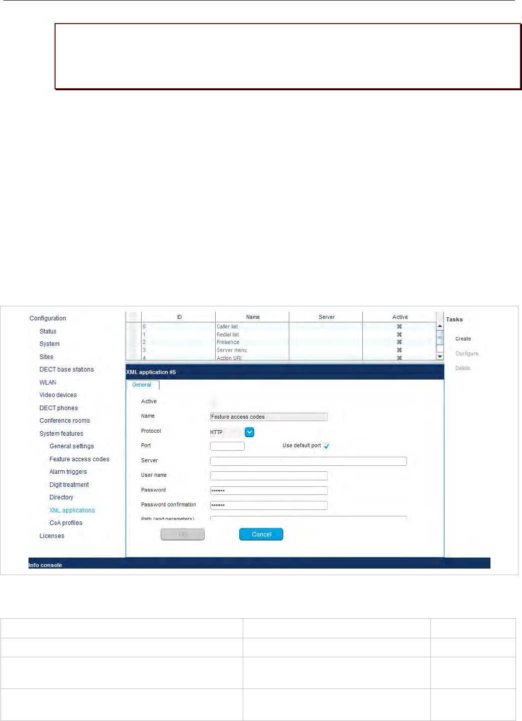
SIP-DECT OM System Manual
208
Please note: “Caller list” and “Redial list” replace the local caller and redial lists of the
Mitel 600 if activated. Additionally the list access must be set to “Automatic” or “PBX” on
the DECT phone in the “Settings > List access” menu. If the list access is set to “Local”,
the local list is used by the DECT phone.
Note: An XML directory entry is also read-only listed in the XML
applications menu. For information on configuring XML
directories please see section 6.12.5.1.
An activated hook becomes available on a DECT phone (including the corresponding menu entry) after
the next DECT location registration of the DECT phone. This can be forced by switching the DECT
phone off and on. The same applies if a hook is deactivated.
XML terminal interface application – selecting a menu entry on the DECT phone
When a “TextMenu” XML object is displayed on the DECT phone, the user can move with the “Up” and
“Down” arrow keys to an entry and select the highlighted entry by pressing the “OK” key.
Alternatively the user can press the digit keys to select a displayed entry. The digit key refers to the
displayed line number which shall be selected e.g. 1 selects the first menu line, 2 the second menu line
and so forth.
The tasks which can be performed in the XML applications menu are mode-dependant.
Configuration mode Monitor mode See section
Create: create new XML hooks 6.12.6.1
Configure: configure selected XML hook in
detail panel 6.12.6.2
Show details: shows selected XML
hook in detail panel 6.12.6.3
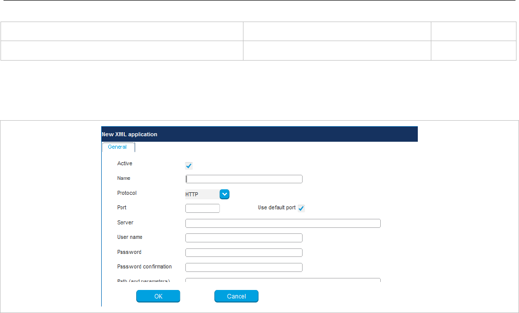
OM Management Portal (OMP)
209
Configuration mode Monitor mode See section
Delete: delete selected XML hook 6.12.6.4
6.12.6.1 Creating a New XML Hook
In addition to the six predefined XML hooks, you can create up to 10 additional XML hooks.
Adding individual XML hooks is only possible in Configuration Mode. To add an XML hook proceed as
follows:
1 In the Tasks bar click on the Create command.
The New XML application panel opens.
2 Configure the XML hook, see parameter description below.
3 Press the OK button.
The following parameters can be set in the tabs of the New XML application panel:
• Active: This setting activates or deactivates a configured XML application entry.
• Name: The predefined hooks have fixed predefined names. A name must be configured for the free
defined hooks.
The following parameters specify the URI:
• Protocol: Select the protocol HTTP or HTTPS.
• Server: Enter the IP address or the name of the server which provides the XML content.
Note: SIP-DECT 6.0 and later supports “SIPProxy” placeholders for
XML Server application URLs within SIP redundancy setups. In
cases where applications are located on a SIP server, it is
necessary to address XML applications by using the current
primary, secondary or tertiary SIP server address. In those
cases, the “SIPProxy” placeholder can be used as server input.
• User name: Enter the login user name if an authentication is required by the server.
• Password, Password confirmation: Enter the password if the authentication is required by the
server.

SIP-DECT OM System Manual
210
• Path (and parameter): Enter the path and query of the URI. For “Feature access codes translation”,
the Path settings contains placeholders for the queried translation: {subsc} = Number, {ppn} = Device
ID, {fac} = FAC
6.12.6.2 Changing an XML Hook
Changing XML hooks is only possible in configuration mode. To change the configuration of an
existing XML hook, do the following:
1 Select the appropriate XML hook in the account table.
2 In the Tasks bar, click Configure.
3 Change the XML hook parameters (see parameter descriptions in section 6.12.6.1).
4 Click OK.
Note: The predefined XML hooks cannot be renamed.
6.12.6.3 Viewing XML Hook Details
You can view the configuration of an XML hook in Monitor Mode. Do the following:
1 Select the appropriate XML hook in the table.
2 In the Tasks bar click on the Show details command.
The user account data is displayed in the user account detail panel.
3 Click Cancel to close the XML hook detail panel.
6.12.6.4 Deleting XML Hooks
Deleting XML hooks is only possible in Configuration Mode. To delete one or more existing XML hook,
do the following:
1 Select the appropriate XML hook(s) in the table by activating the corresponding checkbox(es).
2 In the Tasks bar, click Delete.
A confirmation dialog opens.
3 Click OK to confirm.
Please note: The predefined XML hooks cannot be removed.
6.12.7 “COA PROFILES” MENU
SIP-DECT 6.0 and later supports central configuration over the air (CoA) for Mitel 602 DECT phones.
The CoA profiles page lists the available CoA profiles that can be downloaded to the DECT phones.
Note: The profiles generated by the user_common.cfg configuration file
are also listed in this window. When managed with OMP, they
can be overwritten when the user_common.cfg configuration file
is reloaded. The maximum download size is 4kB.
You can import CoA profiles via the CoA Profiles menu. Once you have imported the profiles, you can
assign them to specific DECT phone users.
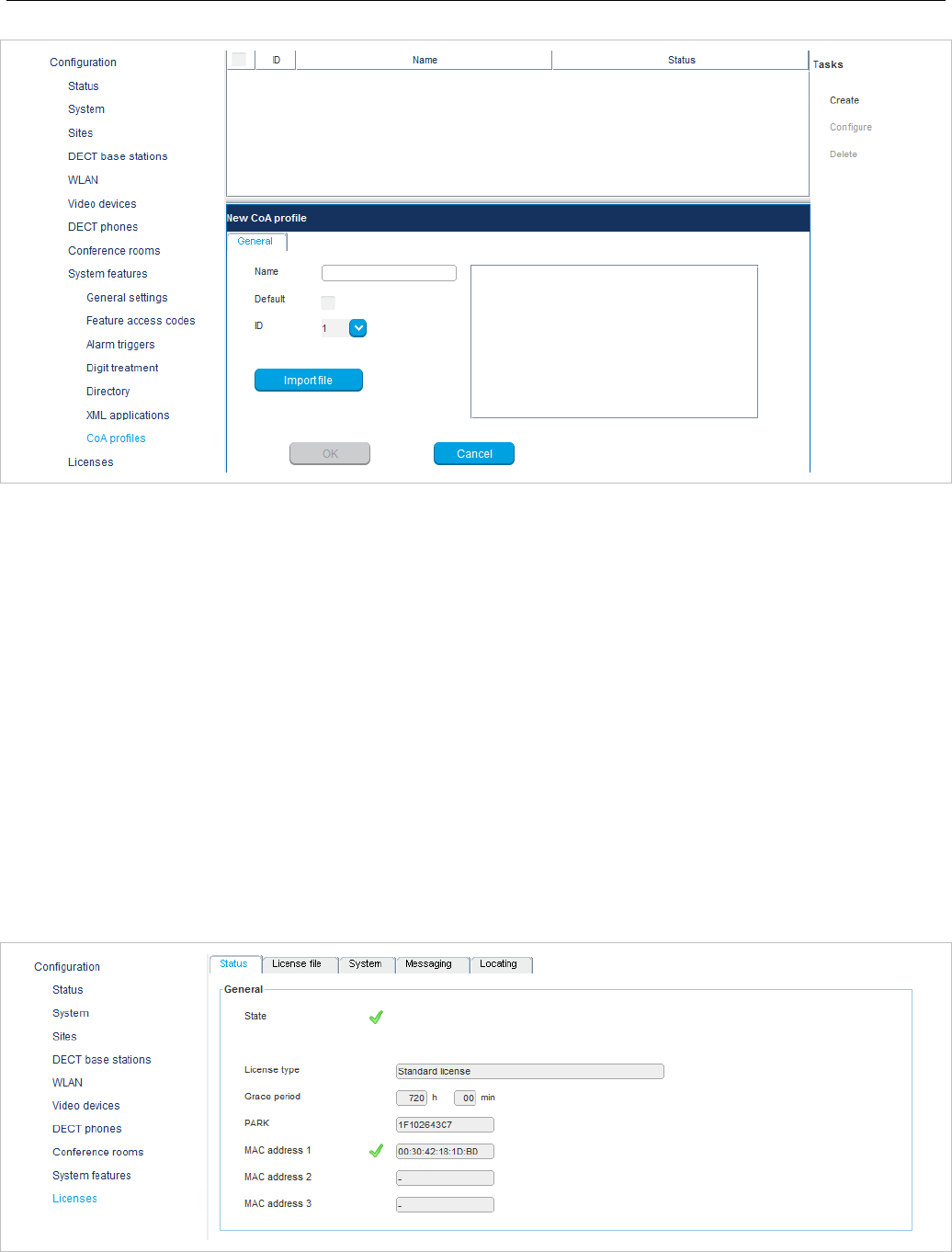
OM Management Portal (OMP)
211
To create a new CoA profile:
1 Click Create under the Tasks list on the right-hand side of the CoA profiles window.
The New CoA profile dialog opens.
2 Configure the settings for the CoA profile:
- Name: Specify a name for the CoA profile
- Default: Indicate whether this is the default CoA profile to be used
- ID: Select an ID for the CoA profile from the drop-down menu.
3 Click Import file to select the CoA file to import.
The CoA profiles page displays the new CoA profile in the table.
6.13 “LICENSE” MENU
The License panel provides an overview of licenses currently in use. In Configuration Mode, you can
also import a license file.
The license information is displayed in the following tabs:
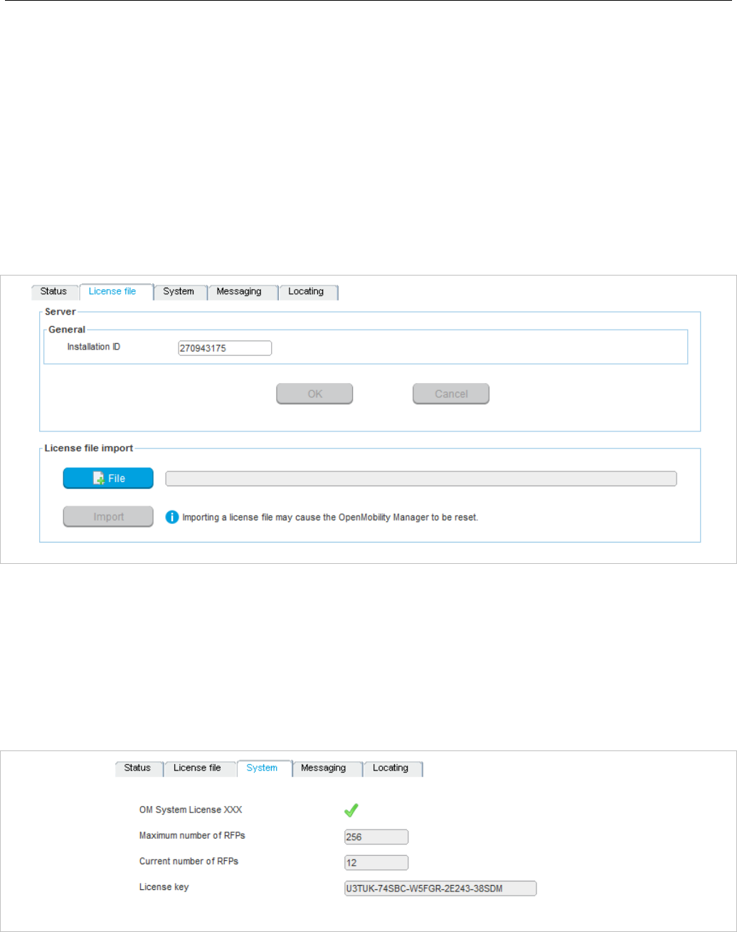
SIP-DECT OM System Manual
212
• Status: shows general license information.
• License file: allows import of a license file
• System: shows system license status.
• Messaging: shows Integrated Messaging and Alerting Service (IMA) license status.
• Locating: shows Locating license status.
“General” tab
The General tab displays general information about the current system license.
“License file” tab
The License file tab allows you to import a license file (only possible in Configuration Mode).
1 Click the File button to select the path and file name where the license file is stored.
2 Click the Import button.
“System” tab
The “System” tab provides OM System license information. This includes supported software version
and number of licensed DECT base stations (RFPs) compared to number of connected DECT base
stations.
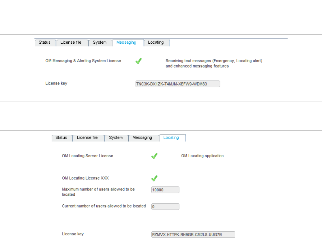
OM Management Portal (OMP)
213
“Messaging” tab
The “Messaging” tab provides OM Messaging and Alerting license information.
“Locating” tab
The “Locating” tab provides OM Locating license information.
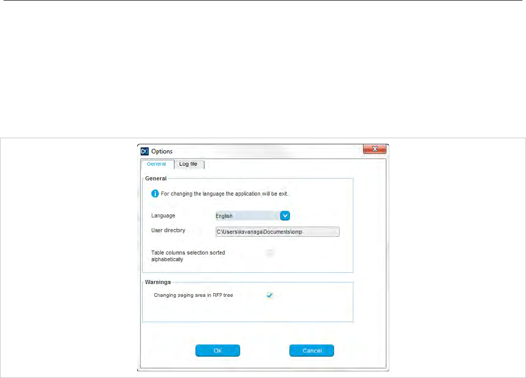
SIP-DECT OM System Manual
214
6.14 “GENERAL” MENU
The General menu is available in all program situations. It contains following submenus:
• Exit: Selecting this menu entry opens the exit dialog to close the OMP.
• Options: Selecting this menu entry opens the Options dialog (see below).
“Options” - “General” tab
Language: You can select the OMP language. After changing the language, the OMP is automatically
closed and must be started again.
The field User directory shows the path where the following files are saved if necessary:
• System dump file “sys_dump.txt”
• Expert console log file “spy.log” when the application terminates
• Exception log file “spy_trace_<date>_pxxx” in case of a Java exception, file name extension “xxx”
ranges from 000 to 999
In the Warnings section you can activate/deactivate the display of warning messages in the OMP.
Notes on log files
The mechanism for creating the log files is the same as the PC OMM spy log mechanism, what means:
• The maximum size of the log file is 1 GB
• 1000 log files per day at maximum
• Only the 30 newest created log files are kept, older ones are removed automatically
• Log files older than 6 days are removed
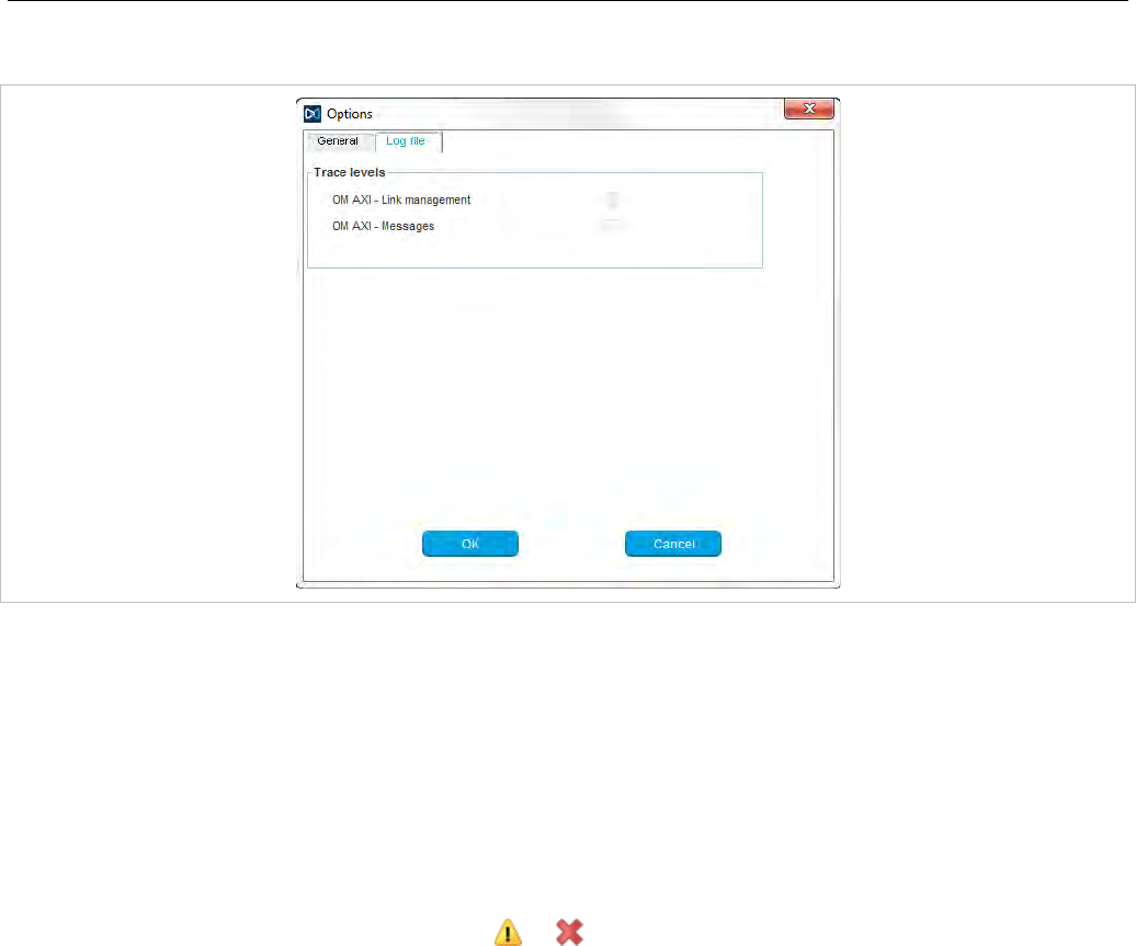
OM Management Portal (OMP)
215
“Options” - “Log file” tab
In the Log file tab you can enable several trace levels.
6.15 “HELP” MENU
The Help menu is available in all program situations. It contains following submenus:
• Info: Selecting this menu entry displays the End User License Agreement (EULA).
• About AXI: Selecting this menu entry displays the About AXI dialog. This dialog compares the
protocol version numbers which are provided by the OMM with the protocol version numbers
supported by the OMP. The warning icons or show a version mismatch. A version number “-”
means the protocol element is not used by OMP.
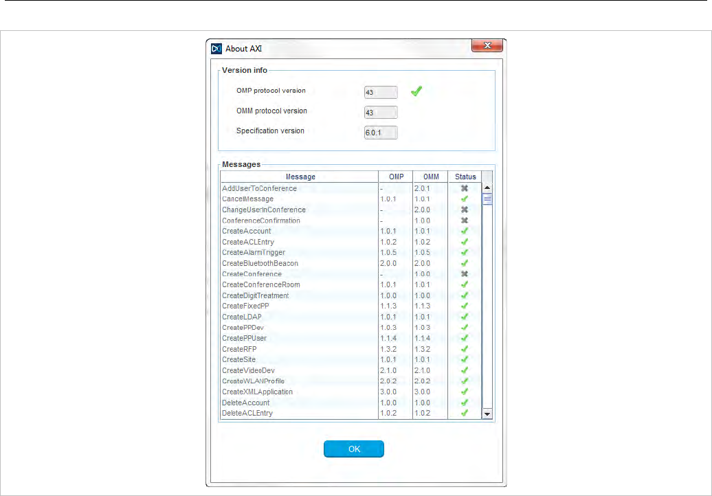
SIP-DECT OM System Manual
216
• About OMP: Selecting this menu entry displays the OMP version info and copyright.
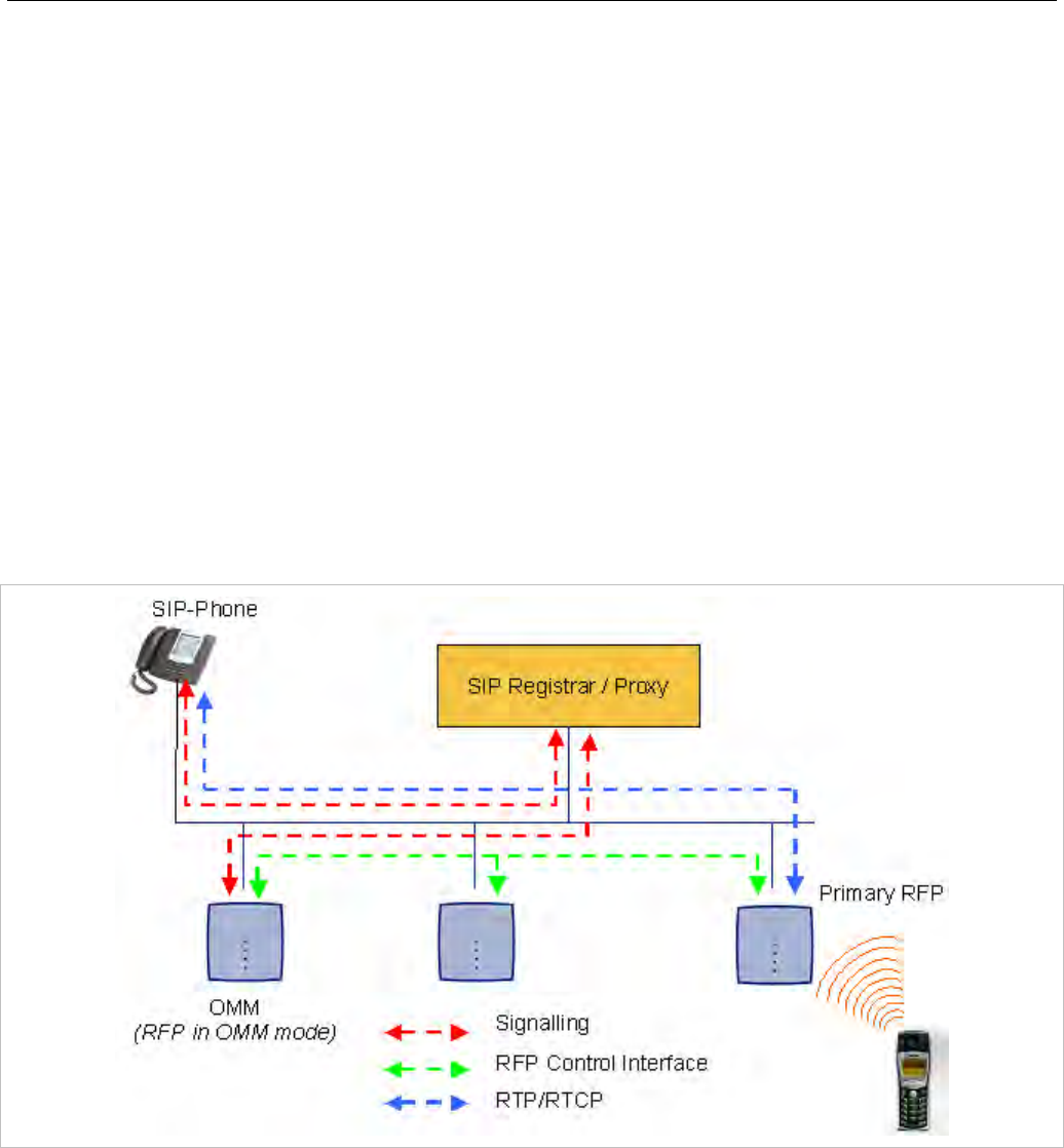
Configuration and Administration
217
7 CONFIGURATION AND ADMINISTRATION
This section provides detailed information on various configuration and administration aspects of the
SIP-DECT solution.
7.1 IP SIGNALING AND MEDIA STREAM
To establish a call between an IP Phone and a DECT phone (e.g. Mitel 600 ), the following IP streams
must be established:
• A signaling channel to and from the SIP phone.
• A signaling channel to and from the OMM.
• A control interface between the OMM and the RFP that has a connection to the DECT phone (known
as the primary RFP).
• A Real Time Protocol (RTP) / Real Time Control Protocol (RTCP) connection between the SIP phone
and the primary RFP.
The following figure illustrates this scenario.
To establish a call between two DECT phones, the same IP streams must be established like in the
scenario before, except the IP phone is not involved. The following figure illustrates this scenario.
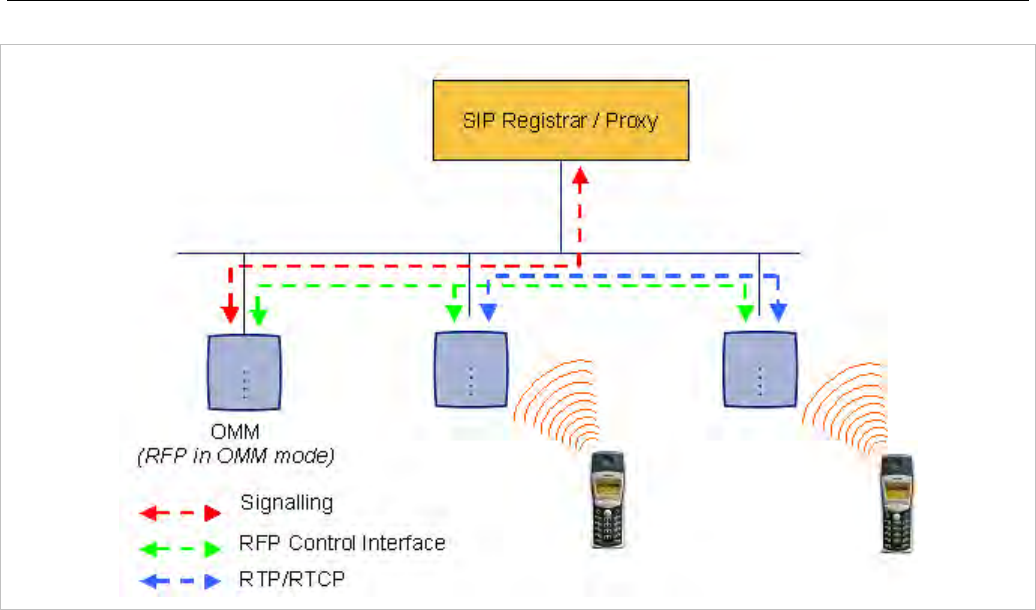
SIP-DECT OM System Manual
218
A call from one DECT phone to another that resides on the same RFP will loop back within the RFP if no
media gateway is involved. So the call will not pass through to the Local Area Network (LAN). Although
the voice packets will not impact LAN traffic, signal packets will.
If the DECT phone user is moving, the DECT phone detects that another RFP has a better signal
strength and, therefore, it starts the handover process. The media stream from the IP phone cannot
move to the secondary RFP, so the primary RFP uses the LAN to direct the voice to the secondary RFP,
as shown in the following figure.
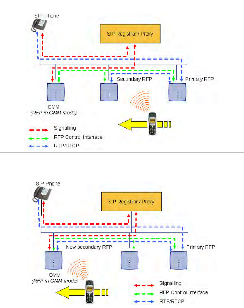
Configuration and Administration
219
As the DECT phone user moves into the next RFP zone of coverage, the DECT phone detects that the
RFP has a better signal strength. Again the media stream from the SIP phone cannot move to the
secondary RFP, so the primary RFP uses the LAN to direct the voice to the new secondary RFP.
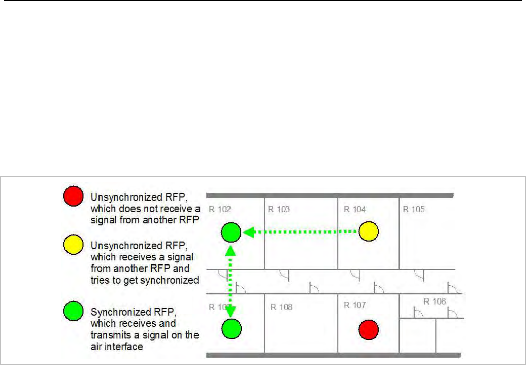
SIP-DECT OM System Manual
220
7.2 RFP SYNCHRONIZATION
To guarantee a seamless handover if a caller moves from one RFP zone of coverage to another RFP
zone of coverage, an accurate synchronization of the RFPs is necessary.
The RFPs are synchronized over the air interface. The first RFP to complete startup will transmit a signal
on the air for the other RFPs to synchronize from. If an RFP gets in sync, then it will transmit a signal on
the air and will be the sync source for the next RFP. Only RFPs which can receive a synchronization
signal will become synchronized.
For the RFP to sync to another RFP the signal strength cannot drop below -70 dBm. You must consider
this requirement during the site survey.
As long as an RFP is not in sync, no calls can be established using this RFP.
If an RFP loses the synchronization, the RFP does not accept new calls (“busy bit”). There is a delay of
maximum 3 minutes until the active calls on this RFP are finished. Then it tries to get synchronized
again.
A SIP-DECT installation is more reliable if an RFP can receive the signal from more than only one RFP
because the other signals are also used for synchronization.
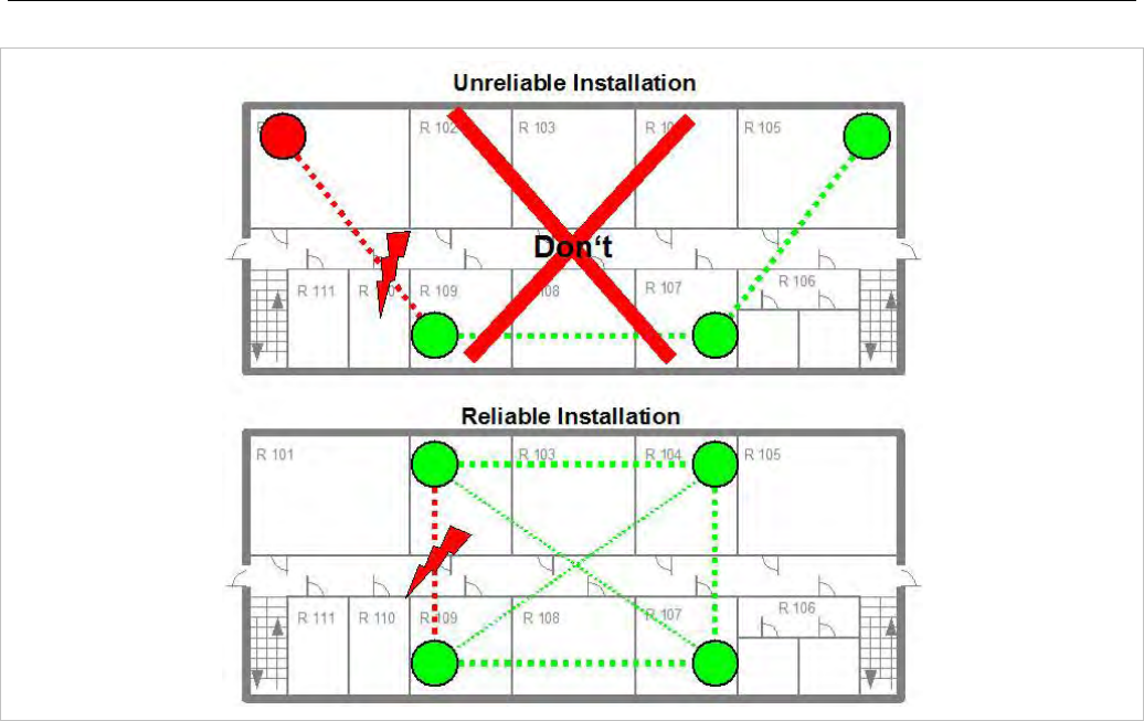
Configuration and Administration
221
The sync-over-air solution is very reliable because all existing redundant paths are used for
synchronization. Thus, hardware tolerances have only very little influence. No RFP has a key position.
Only unfavorable setups without redundant synchronization paths can cause problems.
Sometimes RFPs do not must be synchronized, e.g. if they are in different buildings. These RFPs can be
put into different clusters. RFPs in different clusters will not be synchronized with each other. Different
clusters start up at the same time independently.
7.2.1 INITIAL SYNCHRONIZATION PROCEDURE
To avoid synchronization problems and to speed up the synchronization on system startup, an initial
synchronization procedure is used. For every cluster the following synchronization stages are defined.
• Synchronization stage 0
- If at least one preferred RFP was configured, the synchronization process will wait up to 30
seconds for an incoming startup message of such a preferred RFP. Receiving a message will
finishing stage 0 and the synchronization process jumps to stage 1.
- If no message was received within the 30 seconds this stage will be terminated and the next stage
will be started.
- If no preferred RFP was configured, this stage will be ignored.
• Synchronization stage 1
- If a preferred RFP was determined in stage 0, this one will be the synchronization source for the
next upcoming RFPs. Otherwise the first RFP which sends a startup message will be the
synchronization source for the next upcoming RFPs.
- In this stage, only RFPs reporting an RSSI value better than -65 dBm are permitted to perform
synchronization.

SIP-DECT OM System Manual
222
- If an RFP has done its synchronization, this RFP will be also a synchronization source for other
upcoming RFPs.
- The initial timeout for this stage is 30 seconds. Whenever an RFP has finished its synchronization
in this stage a new stage timeout value will be calculated.
- If no RFP comes up within the timeout time or if all the upcoming RFPs do not fit the RSSI
threshold, this stage will be terminated and the next stage will be started.
• Synchronization stage 2
- The behavior of this stage is identical to stage 1, but an RSSI threshold value of -70 dBm is
significant.
• Synchronization stage 3
- The behavior of this stage is identical to stage 1, but an RSSI threshold value of -75 dBm is
significant.
• Synchronization finished
- No more RSSI threshold value is significant. All RFPs that failed the stage conditions above are
now permitted to perform synchronization.
The last level “synchronization finished” will be achieved either all registered RFPs of this cluster are
synchronized or the timer of stage 3 expires.
7.2.2 CHECKING THE SYNCHRONIZATION OF A NETWORK
For every cluster a periodically check of the synchronization of the network is done. If the network is split
into at least two subnets, all the RFPs of the lesser subnet(s) will be resynchronized. While doing initial
synchronization procedure this check is deactivated. You can check the RFP synchronization using the
Sync view menu of the OM Management Portal (OMP), see section 6.7.6.
7.3 RFP CHANNEL CAPACITY
The RFP has 12 available time slots on air; eight can have associated DSP/media resources for media
streams. All DECT time slots are used for control signaling, software download over air, messaging and
bearer handover independent of associated DSP/media resources.
If all eight media stream channels are used, the RFP announces a “busy bit”. In that case, the DECT
phones determine whether another RFP has an appropriate signal strength. If so, the DECT phone will
handover to that RFP. Once the handover has been completed, the RFP will then lower its “busy bit”.
Whenever the busy state is announced a log entry is made to the system logs. If the announcement of
busy raises in a specific area, a further RFP should be installed to double the number of media streams
available for calls.
Notes on Hi-Q connections
Each Hi-Q connection uses, compared to conventional narrowband, the double capacity on the DECT air
interface. Due to this fact, four Hi-Q connections (instead of eight) can be established via one RFP.
It is not possible to have DECT XQ audio combined with Hi-Q audio within the same connection.

Configuration and Administration
223
7.4 NETWORK INFRASTRUCTURE PREREQUISITES
To establish and maintain an SIP-DECT installation, a network infrastructure is assumed, which
comprises at least the following components:
• RFPs
• DECT phones
• IP PBX/media server (e.g. Asterisk)
• TFTP server
Depending on the operational modes the following services should be provided:
• DHCP
• TFTP
• SNTP
• DNS
• LDAP
• Syslog daemon
Notes on network infrastructure prerequisites
• In NA outdoor RFPs may only be installed with the antennas shipped with the units. No other
antennas or cabling are permitted. In EMEA the outdoor RFPs are shipped without antennas and you
may use the units with one of the optional antennas (separate order no.).
• A TFTP server is no longer required for boot of an RFP 35/36/37 IP or RFP 43 WLAN.
• TFTP, FTP(S), HTTP(S), SFTP are supported for RFP 35/36/37 IP or RFP 43 WLAN software
update.
7.5 SIP-DECT STARTUP
This section contains detailed information on the startup (booting) process of the SIP-DECT solution.
For booting an RFP 32/34 or RFP 42 WLAN, there must be at least one TFTP server on the attached
network to load the OMM/RFP application software.
RFP 35/36/37 IP or RFP 43 WLAN uses the internal flash to start the boot image. A fileserver is only
needed for software update over the network.
The essential network settings can be alternatively:
• Communicated by a DHCP server at startup time.
• Configured on the RFP with the OM Configurator tool (see section 7.6). The settings made by the OM
Configurator will be saved permanently in the internal flash memory of each OMM/RFP.
7.5.1 TFTP AND DHCP SERVER REQUIREMENTS
TFTP server requirements
The RFP gets the boot image file from a TFTP server. The requirement list for the used TFTP server is
defined as follows:
• The support of RFC 1350 /1/ is mandatory.
• To accelerate the download of a boot image file for older 2nd generation RFPs, it is possible to
increase the packet size of the transmitted TFTP packets from 512 bytes per packet to 1468 bytes per
packet. To use this optional feature, the TFTP server must support RFC 2347 /3/ and RFC 2348 /4/.

SIP-DECT OM System Manual
224
• To reduce the overall download time of the older 2nd generation RFPs in a system, it is possible to use
TFTP multicast download. To use this optional feature, the TFTP server must support RFC 2090 /2/
and RFC 2349 /5/.
To use the TFTP multicast option, the attached network must support multicast too. Furthermore a
support of IGMP, RFC 2236 /6/ is required.
Note: If many RFPs loading the boot image simultaneously, the
network load could increase significant. To balance the network
load or for backup reasons, it is possible to configure more than
one TFTP server in a network.
DHCP server requirements
A DHCP server needs to support RFC 2131 /9/. The TFTP and DHCP server need not to reside on the
same host.
7.5.2 BOOTING STEPS
Booting is performed in two steps:
1 Starting the boot process.
2 Starting the application.
Booter startup
On startup each RFP tries to determine its own IP address and other settings of the IP interface from the
configuration settings in the internal flash memory. If no settings are available or these settings are
disabled, the RFP tries to determine these settings via DHCP. Depending on the RFP type, the RFP
software is to be loaded:
• A 3rd generation RFP gets the application image from internal flash memory.
• An older 2nd generation RFP only has a small standalone application built into the flash. This software
realizes the so-called net boot process. The RFP gets the application image file from the TFTP server.
Application startup
After starting the application image, the RFP software checks the local network settings in its internal
flash memory. If no settings are available or if they are disabled, the RFP software starts a DHCP client
to determine the IP address of the OMM and other application startup settings. The RFP software
acquires the OMM IP address
• within the local network settings, if active
• via DHCP request
• RFP configuration file (see 7.7.7)
If the IP address of the actual RFP device matches one of the acquired OMM IP addresses, the RFP
software continues in OMM mode. Otherwise, the RFP runs as normal RFP without OMM mode.
Note: Only 3rd generation RFPs are able to run in OMM mode while
older 2nd generation RFPs cannot function as OMM.

Configuration and Administration
225
7.5.3 BOOTER STARTUP
The SIP-DECT RFP software includes a booter with the following features:
• VLAN can be configured via the OM Configurator without a static IP configuration. This means that
the first DHCP request will be done by using VLAN.
• To balance the network load with older 2nd generation RFP devices, up to three TFTP servers can be
configured. This can be done using the OM Configurator (local setting) or using the DHCP option 150.
Before starting the download, the TFTP server will be selected randomly by the booter. But, if the
option “Preferred TFTP server” was set by the OM Configurator, the option “TFTP server address” will
specify the TFTP server to use. No randomly selection will be done in this case.
• Older 2nd generation RFPs only: to reduce the number of TFTP packets sent by the TFTP server, the
packet size can be increased. This will be done by using a TFTP option (see 7.5.1 “TFTP server
requirements”).
• Older 2nd generation RFPs only: Multicast TFTP download is possible if the TFTP server and the
connected network support this.
• To indicate the actual state of the booter, the LEDs of the RFP will be used (see 7.5.5).
7.5.3.1 DHCP Client
Within the initial boot process the DHCP client supports the following parameters:
• IP address mandatory
• Net mask mandatory
• Gateway mandatory
• Boot file name mandatory for older RFPs
• TFTP server mandatory for older RFPs
• Public option 224: “OpenMobility” / “OpenMobilitySIP-DECT” mandatory
• VLAN-ID optional
• TFTP server list optional
7.5.3.1.1 DHCP Request
The DHCP client sends the vendor class identifier (code 60) “OpenMobility3G” (3rd generation RFPs) or
“OpenMobility” (older 2nd generation RFPs) and requests the following options in the parameter request
list (code 55):
• Subnet mask option (code 1)
• Router option (code 3)
• VLAN ID option (code 132)
• TFTP server list (code 150)
• Public option 224 (code 224) (string “OpenMobility” or “OpenMobilitySIP-DECT”)
• Public option 225 (code 225) (VLAN ID, not relevant for SIP-DECT)
• Public option 226 (code 226) (not relevant for SIP-DECT)

SIP-DECT OM System Manual
226
7.5.3.1.2 DHCP Offer
The DHCP client selects the DHCP server according to the following rules:
• The public option 224 (code 224) has a value equal to the string “OpenMobility”,
or
• the public option 224 (code 224) has a value equal to the string “OpenMobilitySIP-DECT”.
If none of the two rules above match, the DHCP offer is ignored.
Information retrieved from the DHCP offer:
• The IP address to use is taken from the yiaddr field in the DHCP message.
• The IP net mask is taken from the subnet mask option (code 1).
• The default gateway is taken from the router option (code 3).
• The TFTP server IP address is taken from the siaddr field in the DHCP message and additionally
DHCP option 150, if available.
• The boot image filename is taken from the file field in the DHCP message, if this field is empty, the
default filename is used.
7.5.3.1.3 Retries
If the DHCP client does not get an appropriate DHCP offer, a new DHCP request is send after 1 second.
After 3 DHCP requests are sent the DHCP client will sleep for 60 seconds. During this time the booter
will accept a local configuration with the OM Configurator.
This cycle will repeat every 3 minutes until either all the required DHCP options are provided or the
system is manually configured using the OM Configurator tool.
7.5.3.2 TFTP Client
The TFTP client will download the application image from the TFTP server. Both TFTP server and the
name of the application image are supplied via the DHCP client. The application image is checksum
protected.
Downloading the application image via TFTP is mandatory for older 2nd generation RFPs only. 3rd
generation RFPs will load the application image from the internal flash, and (if configured) also download
the application image via TFTP for update.
7.5.3.3 Booter Update
With older second generation RFPs, each application software image comes with the latest released
booter software. The application software will update the booter automatically. With third generation
RFPs, the booter will only be updated if you update the software.
If you downgrade the RFP’s application software image to an older release, the booter will not
downgrade automatically. In addition, if you want to use the OM Configurator tool (see 7.7), the OM
Configurator version must match the booter software version.

Configuration and Administration
227
7.5.4 APPLICATION STARTUP
After successfully starting the application software, the RFP checks the local network settings in its
internal flash. If no settings are available or if they are disabled, it starts a DHCP client to determine the
IP address of the OMM and other application startup settings.
7.5.4.1 DHCP Client
The DHCP client is capable of receiving broadcast and unicast DHCP replies. Therefore the flags field is
0x0000. The DHCP request contains the well-known magic cookie (0x63825363) and the end option
(0xFF).
Parameters
The following parameters will be supported within this step:
Option / Field Meaning Mandatory
yiaddr IP address of the IP-RFP yes
siaddr Parameter named “Boot Server Host Name” with value
as the IP address of the TFTP server no (3G RFPs)
yes (older 2G
RFPs)
File Parameter named “Bootfile Name” with value of the
path (optional) and name of the application image. For
example “iprfp3G.dnld “ (3rd generation RFPs) or
“iprfp2G.tftp” (older 2nd generation RFPs).
no (3G RFPs)
yes (older 2G
RFPs)
option 1 Subnet mask no
option 3 Default Gateway no
option 6 Domain Name Server no
option 15 Domain Name no
option 42 IP address of a NTP server no
option 43 Vendor Specific Options yes
option 66 URL specifies the protocol, server and path to access
the RFP configuration files (see 7.7.7). no
option 132 VlanId no
option 150 TftpServerIpList no
option 224 Parameter named magic_str must be set to value
"OpenMobility" or "OpenMobilitySIP-DECT". yes

SIP-DECT OM System Manual
228
Vendor specific options
The Vendor Specific Options consist of:
Vendor Specific Option Meaning Length Mandatory
option 10 ommip1: Used to select the IP-RFP who should
reside the Open Mobility Manager (OMM). 4 yes
option 14 syslogip: IP address of a Syslog Daemon 4 no
option 15 syslogport: Port of a Syslog Daemon 2 no
option 17
(SIP-DECT 5.0 and older) Country: Used to select the country in which the
OMM resides. This enables country specific
tones (busy tone, dial tone, …).
2 no
option 18
(SIP-DECT 5.0 and older) ntpservname: Name of a NTP Server x no
option 19 ommip2: Used to select a secondary IP-RFP
who should reside the standby Open Mobility
Manager (OMM). This option must be given if
the OMM Standby feature should be used (see
section 7.15).
4 no
option 43 code 2 Provisioning URL: URL for an external file
server, from which all configuration files can be
downloaded.
no
Example
An example of the minimal contents for the Option 43 parameter value would be:
0a 04 C0 A8 00 01 where “C0 A8 00 01” represents “192.168.0.1” for the OMM IP.
The option 43 contains a string of codes in hex the format is “option number” “length” “value” in this
example
0a = option 10 (ommip1)
04 = following value is 4 blocks long
C0 A8 00 01 = 192.168.0.1
If there is more than one option, add the next option at the end of the previous one. Depending of the
DHCP server you must end the option 43 with FF.
Country specific tones (SIP-DECT 5.0 and older ONLY)
Tones for the following countries are supported:
Country code Country
1 Germany
2 Great Britain
3 Switzerland
4 Spain
6 Italy
7 Russia
8 Belgium
9 Netherlands

Configuration and Administration
229
10 Czechoslovakia
11 Austria
12 Denmark
13 Slovakia
14 Finland
15 Hungary
16 Poland
17 Belarus
18 Estonia
19 Latvia
20 Lithuania
21 Ukraine
22 Norway
24 Sweden
25 Taiwan
100 North America
101 France
102 Australia
7.5.4.2 Configuration using DHCP
The DHCP client of the RFP family requests several parameters that are used to configure the RFP. The
DHCP client vendor class identifier (option 60) is different for the different RFP generations:
• 3rd generation RFPs (RFP 35/36/37 IP / RFP 43 WLAN) use “OpenMobility3G”.
• Older 2nd generation RFPs (RFP 32/34 / RFP 42 WLAN use) “OpenMobility”.
BOOTP/DHCP
Option
Meaning Type Remarks
siaddr IP address of the
TFTP server 4 octets Optional for 3G RFPs for SW
update;
Mandatory for older 2G RFPs
because of the NETBOOT
process;
File Path to the boot
image server by the
TFTP server
N octets Optional for 3G RFPs for SW
update;
Mandatory for older 2G RFPs
because of the NETBOOT
process
150 TFTP server list N * 4 octets Only used by the NETBOOT
process of older 2G RFPs
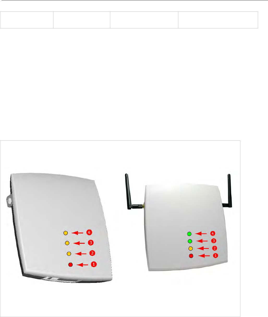
SIP-DECT OM System Manual
230
224 Magic String “OpenMobility” or
“OpenMobilitySIP-DECT” The client uses this option to
select the server, mandatory
* The magic string “OpenMobilitySIP-DECT” instead of “OpenMobility” (as defined in SIP-DECT 2.x)
makes sure that a SIP-DECT software is loaded into the RFP 35/36/37 IP/ RFP 43 WLAN even an
different, non-SIP-DECT SW is previously installed and running.
7.5.4.3 Selecting the Right DHCP Server
The DHCP client requests its own IP address using code 50. The DHCP client will select the DHCP
server that offers the currently used IP address. Additionally the mandatory options must be offered
otherwise the DHCP offer is ignored by the DHCP client.
If no matching reply was received, the DHCP client resends the request 2 times after 1 second. Then the
DHCP client will wait for 1 minute before resending 3 requests again.
If the DHCP client cannot accept a DHCP offer within 30 minutes, the RFP is rebooted.
7.5.5 RFP LED STATUS
RFP 32/34 IP
RFP 32/34 NA
RFP 35/36 IP
RFP 42 WLAN
RFP 43 WLAN
LED 1 Info / Booter; LED 2 System;
LED 3 DECT; LED 4 (unused)
LED 1 Info / Booter; LED 2 System
LED 3 DECT; LED 4 WLAN
The following tables show the LED status of an RFP according to the different states.
A red respectively orange colored field in the table means that the LED glows permanently in red or
orange. A split field with e.g. the specification 1s/1s means that the LED is flashing with a frequency of
one second LED red on and one second LED off. Grey means that the LED is off.
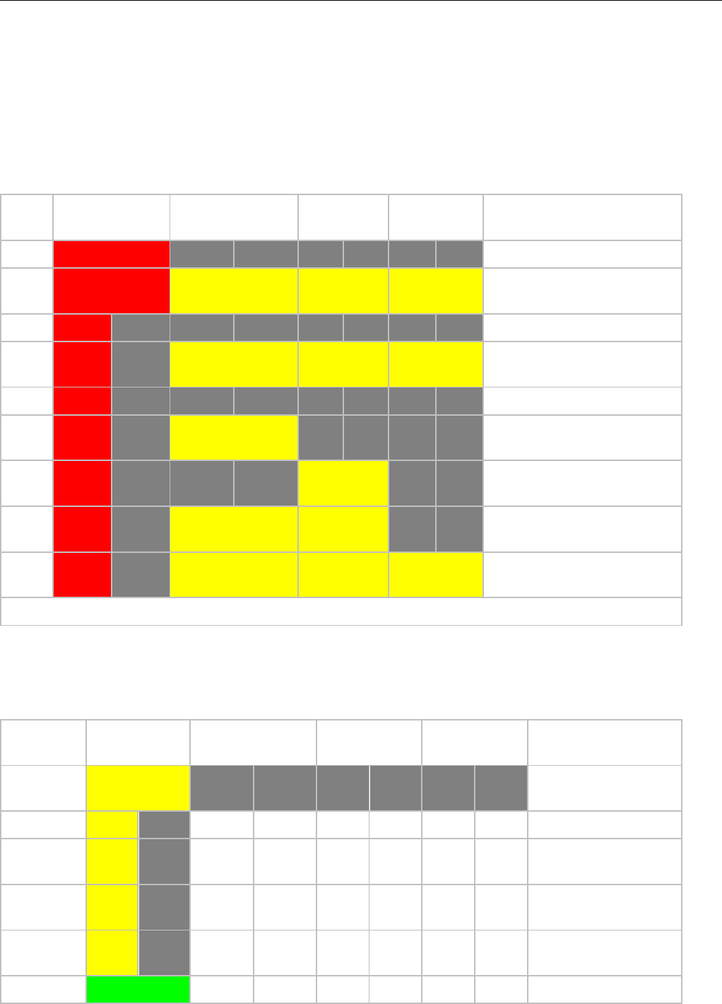
Configuration and Administration
231
7.5.5.1 Booter LED Status
RFP 35/36 IP, RFP 43 WLAN
The RFP 35/36 IP and RFP 43 WLAN booter uses LED1 for signaling its activity. After power up, the
LED 1 (INFO) is red. The successful start of the boot image is signaled by the LED 1 turning orange.
RFP 32/34 IP, RFP 32/34 NA, RFP 42 WLAN
The following table illustrates the different meaning of the LEDs while the booter is active.
LED1 (INFO)
LED2 (OMM /
SYSTE
M)
LED3
(DECT)
LED4
(WLAN)
Booter
cont.
Power connected
cont.
cont.
cont.
cont.
Wait for OMM Configurator
Input
1s
1s
DHCP
1,9s
0,1s
cont.
cont.
cont.
DHCP failed, wait for OMM
Configurator Input
0,25s
0,25s
TFTP download after
DHCP
0,25s
0,25s
cont.
TFTP download after local
configuration
0,25s
0,25s
cont.
TFTP download after DHCP
Multicast
0,25s
0,25s
cont.
cont.
TFTP download after local
configuration and multicast
3,9s
0,1s
cont.
cont.
cont.
TFTP failed, wa
it for OMM
Configurator Input
Now, the kernel / application is running: LED1 will never be RED
7.5.5.2 Application LED Status
The following tables illustrate the different meaning of the LEDs while the application is starting or active.
RFP 35/36 IP, RFP 43 WLAN
LED1 (INFO)
LED2 (OMM /
SYSTEM)
LED3 (DECT) LED4 (WLAN)
Kernel
cont.
kernel boot phase
(inflator, …)
RFPM
1s
1s
DHCP phase
1,85s
0,
5s
DHCP failure (idle
loop)
0,5s
0,5s
obtaining external
configuration
0,85s
0,1
5s
external configuration
failure
cont.
Ready
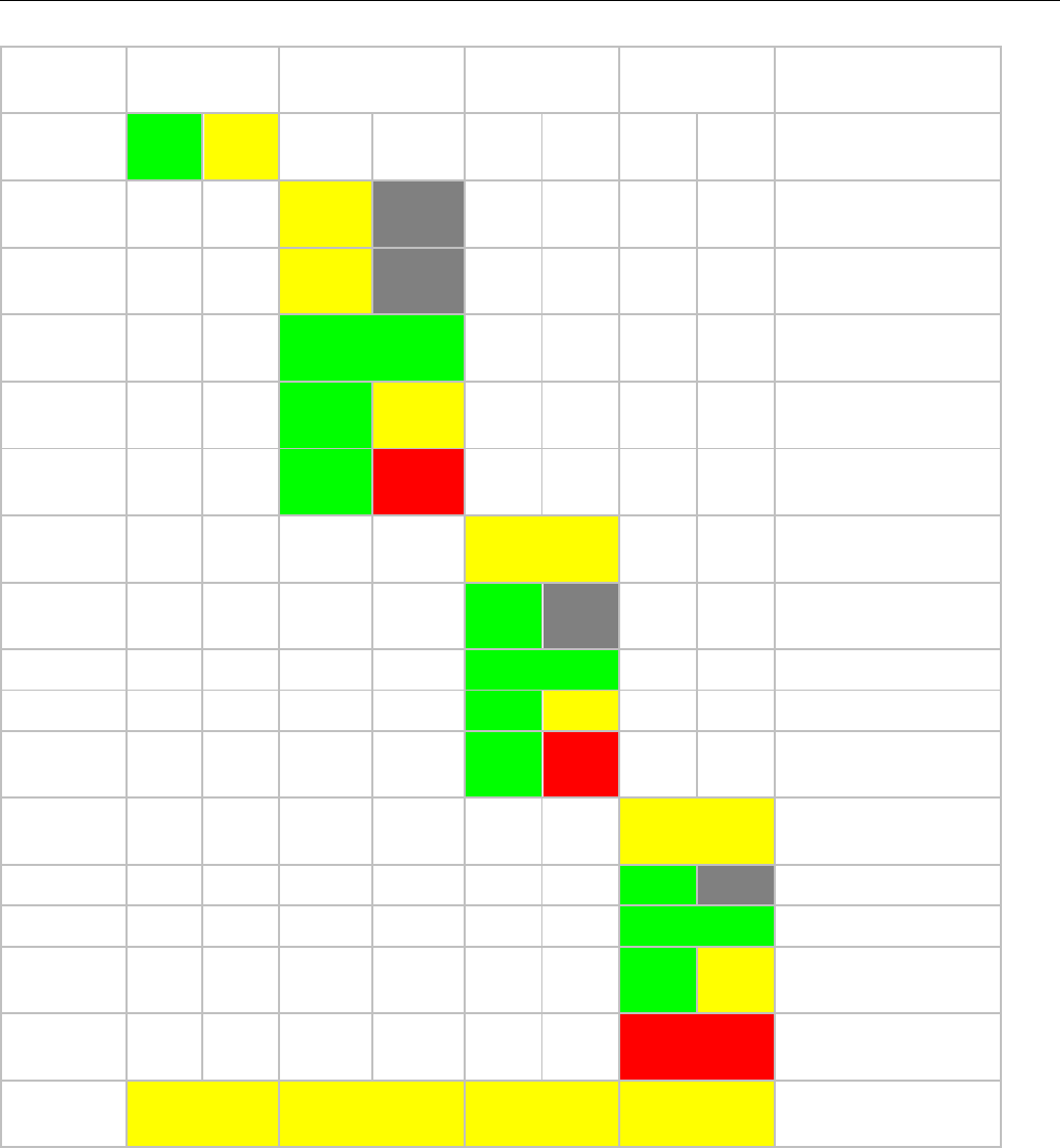
SIP-DECT OM System Manual
232
LED1 (INFO)
LED2 (OMM /
SYSTEM)
LED3 (DECT) LED4 (WLAN)
1,85s
0,15s
Up
& running + RFP
houses OMM
RFP
general
1s 1s
OMM connect phase
1,85s 0,15s
OMM connection
failure (idle loop)
cont.
Up
& running (OMM
connected)
1,85s 0,15s
Up & running
+ OMM
warning
1,85s 0,15s
Up & running
+ OMM
failure
RFP DECT
cont.
DECT not configured
on this RFP
1,85s 0,15s
DECT inactive (not
synced yet)
cont
DECT 'on air'
1,85s 0,15s
DECT + ca
ll active
1,85s 0,15s
DECT + call active
+busy bit
RFP WLAN
cont.
WLAN not configured
on this RFP
1,85s
0,15s
WLAN inactive yet
cont.
WLAN 'on air'
1,85s
0,15s
WLAN + assoc.
clients
cont.
WLAN failure (
e.g.
10
MB uplink)
Reboot
request
cont.
cont. cont. cont.
RFP will reboot
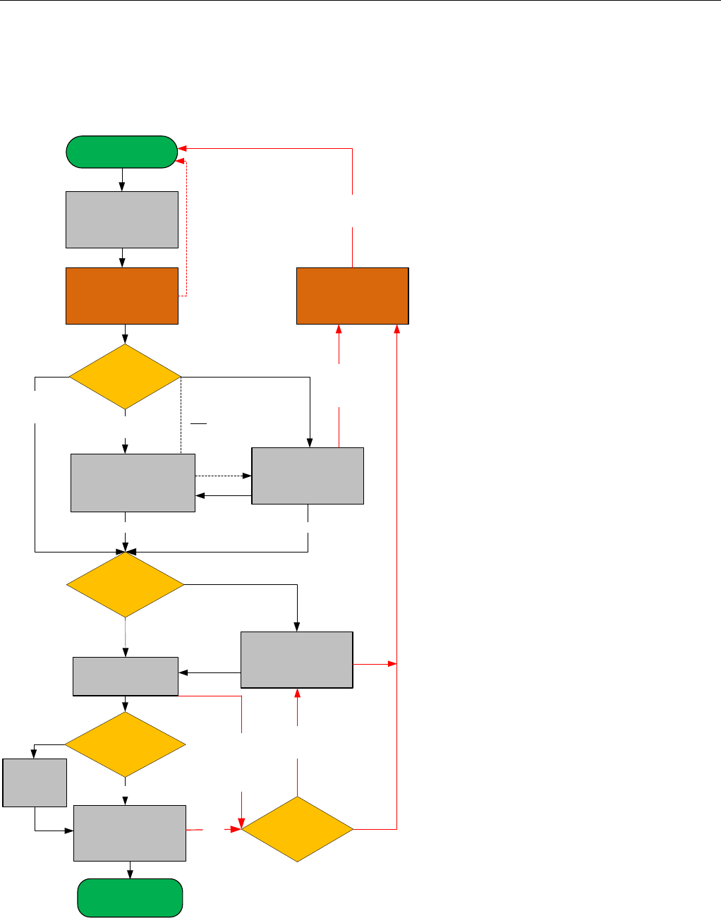
Configuration and Administration
233
7.6 STATE GRAPH OF THE START-UP PHASES
The following figure illustrates the start-up phase for older 2nd generation RFPs. 3rd generation RFPs use
a similar start-up sequence, but they start with the application phase (see below).
wait until
Ethernet link is up
DHCP
Check for Local
Configuration Inactive
active and
VLAN configured
If DHCP
offer with
VLAN code
received Offer is validVLAN ID is in use
wait 6 seconds for
OMM Configurator
input
No OMM Configurator input
wait 60 seconds for
OMM Configurator
input
no offer
or offer
not ok.
after retry.
Timeout or OMM
Configurator
input received
TFTP Download
contact Servers
from List
Server offer
Multicast TFTP
TFTP Server
list
failed
no
IGMP
join group
yes
No other
Server
available
other TFTP
Server
configured
Download failed.
retry other
configured servers
active but
no VLAN
configured
multiple Servers
are configured
Only one server
is configured
contact this server
Power ON
Start
Application Phase
base station reboot
if new configuration
is received by
OMM Configurator
TFTP Download
send read request
failed / timeout
Download failed
only one Server
configured
If only VLAN
is configured
enable
configured
VLAN ID
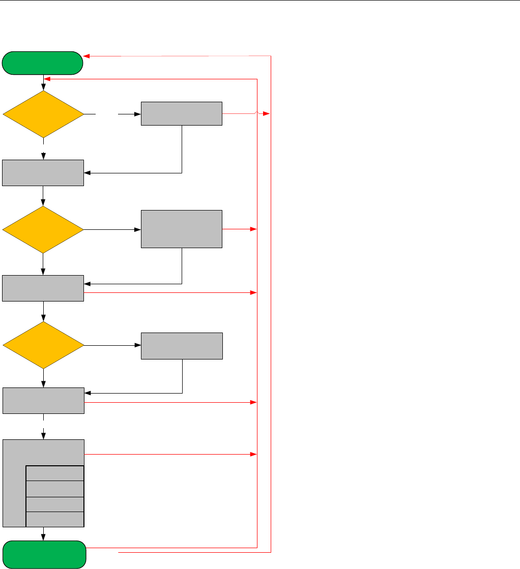
SIP-DECT OM System Manual
234
DHCP
Check for Local
Configuration
Start Application
Phase
enable configured
parameter
Check for RFP
config file
download and
apply RFP
config files
Application
init
connect to OMM
SNMP
start OMM
application
Check for
OMM IP
WLAN
active
inactive
valid offer received
config file server
is set
failed if no valid config
is available on this RFP
not set apply config files
(overwrite local parameter)
this RFP is OMM
failed
apply config from OMM
syslog
DECT
failed
failed
major config change of local configuration
Failure e.g. connection to OMM lost
up & running
DHCP no answer
or offer not okay
(try 3 minutes)
init configured
applications
*
any time
RFP application
connect to OMM
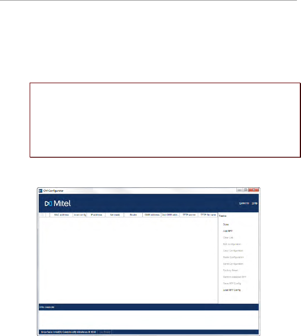
Configuration and Administration
235
7.7 LOCAL DECT BASE STATION CONFIGURATION (OM
CONFIGURATOR)
As an alternative to DHCP configuration, you can use the OM Configurator tool to statically configure the
DECT base stations individually. RFP settings configured through the OM Configurator tool are saved
permanently in the internal flash memory of the RFP. The OM Configurator version must match the
installed SIP-DECT software version to be used for the local configuration of RFPs.
Please note: The OM Configurator requires the Java Runtime Environment version 1.7 or
higher.
Please note: An initial configuration of the RFPs 35/36/37 IP / RFP 43 WLAN via the OM
Configurator tool requires a login and password. The default login and password is “omm”
and “omm”. No login is required for the initial configuration of the previous RFP family
(RFPs 32/34 / RFP 42 WLAN. If the RFP is configured by the OMM later on, the OMM
also sets the configuration password. You must enter the OMM’s full access user and
password in the OM Configurator tool then.
At start-up of the OM Configurator displays a table with configuration data for all RFPs. The task bar on
the right side shows permitted actions. The Info console in the lower part of the window shows
information and errors as they occur during OM Configurator operation
7.7.1 SELECTING THE NETWORK INTERFACE
You can select the network interface of the computer used by the OM Configurator via the General ->
Options menu. The selected interface is shown on the status line of the program.
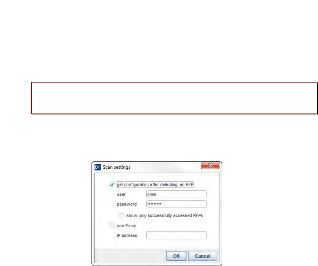
SIP-DECT OM System Manual
236
7.7.2 ADDING RFPS FOR CONFIGURATION
Before you can configure an RFP, you must add the RFP to the OM Configurator database. You can add
an RFP record by:
• scanning for RFPs that are already attached to the network
• entering the MAC address of the RFP
• loading a configuration file that contains RFP MAC addresses and configuration parameters
Please note: Adding an RFP to the OM Configurator database does not modify the RFP
configuration. Configuration data must be transmitted explicitly to the RFP(s) through the
Send Configuration option.
7.7.3 SCANNING FOR RFPS
The OM Configurator tool can scan for RFPs on the LAN segment.
• If get configuration after detecting an RFP is enabled, the OM Configurator attempts to fetch the
local configuration settings from all RFPs that are detected during the scan. The program uses the
user/password combination if an access without login data fails.
• If show only successfully accessed RFPs is enabled, the OM Configurator adds only RFPs that
provide configuration information to its database, and displays those RFPs in the OM Configurator
table.
• The use Proxy parameter allows access to RFPs that are located in network segments other than
the segment that hosts the OM Configurator. The IP-address field must contain the address of a RFP
located in the network segment to be scanned. This RFP works as proxy and must be up and running.
You initiate the scan process by clicking OK button. The OM Configurator adds the results to the table.
In rare cases, it is possible that a RFP is expected to appear in the table after the scan operation but
does not. If this occurs, repeat the scan operation.
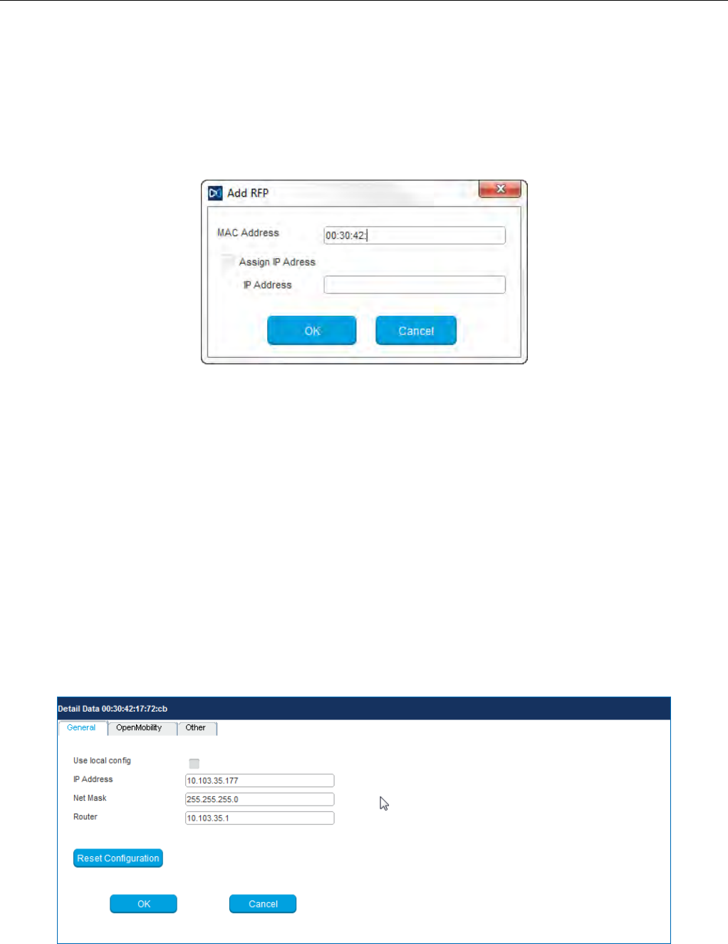
Configuration and Administration
237
7.7.4 ADDING RFPS MANUALLY
You can add an RFP to the OMM Configurator database manually.
When you click the Add RFP option in the task bar, the OM Configurator displays the “Add RFP” dialog.
You must specify the MAC address of the RFP in the MAC Address field.
Optionally, you can also specify an IP address. If an IP address is assigned, the OM Configurator
automatically proposes an incremented IP address the next time the “Add RFP” function is invoked.
7.7.5 LOADING RFP DATA FROM FILE
You can import an RFP configuration file to the OM Configurator.
When you click on the Load RFP Config option, the OM Configurator opens a dialog window that
prompts you to browse for the configuration file. All found valid RFP entries in the file are added to the
OM Configurator database and displayed in the table.
7.7.6 EDITING RFP CONFIGURATION DATA
You can edit the configuration of an RFP stored in the OM Configurator database. When you double-
click on a table row, the OM Configurator displays a Detail Data window below the table, with the
“General” panel activated. You can also access this window by selecting one or more entries in the table
and clicking the Edit configuration option in the task bar.
You can change parameters for multiple RFPs by selecting more than one RFP in the table. Parameter
settings that differ between the selected RFPs are shown as “***” and retain their values if you do not
make any modifications.

SIP-DECT OM System Manual
238
You cannot change the IP address value when you select more than one RFP.
If more than one parameter value is allowed (e.g. Router, DNS addresses), you must separate the
values by a space.
If you click the Reset Configuration button, all configuration parameters are removed and local
configuration in the OM Configurator is disabled. The Send Configuration option is also needed in this
case in order to update the configuration of the RFP locally.
When you click the OK button, changed parameter values are committed to the database. The system
performs validation checks for some parameter values. If this check fails, the system displays an error
message in the Info console and the misconfigured parameter value is marked with a red frame (allowing
you to correct the value). Modified RFP records are marked ( ) beside the corresponding table row.
If you press Cancel or select another RFP in the table, any changes are discarded.
When you press either OK or Cancel, the Detail Data panel disappears and a number of task bar
options (e.g. Send Configuration) are re-enabled.
7.7.6.1 Other parameter panel
You can set and edit less frequently used parameters on the Other panel of the Detail Data window.
If the parameter you want to add or edit is listed in the table on the Other panel, click on it to display the
parameter name and value in the fields on the top-right side of the panel. Click the Change button to
commit the changed value.
If the parameter value field is empty, the parameter is cleared on the RFP when you click Send
Configuration.
You can add a new parameter by selecting a parameter name from the drop-down list and clicking the
New button.
7.7.6.2 Copy and Paste
You can assign parameter values from one RFP to one or more other RFPs.
To perform this operation, you must ensure that the Detail Data window is not active. If the Detail Data
window is open, commit your changes or cancel to close the window.
Select an RFP in the table and click the Copy Configuration option in the task bar. Next, select one or
more RFPs as destination RFP(s) and click the Paste Configuration option. The system displays the
Paste Data dialog window.
If the Assign IP Addresses option is enabled, you must provide a valid IP address in the Start Address
field. The system may display a suggested address, based on a previous paste or Add RFP operation.
The IP address is incremented by one for each RFP.

Configuration and Administration
239
If the Overwrite existing addresses parameter is not enabled, an IP address is only assigned if the IP
address field of the target RFP is empty.
7.7.6.3 Configuration Parameters
The following table lists the available configuration parameters for the RFP.
Parameter Mandatory/Optional Description
Use local configuration Mandatory Specifies whether the local configuration settings should
be used at boot-up or not
IP address Mandatory IP address of the RFP
Net mask Mandatory Subnet mask of the IP network
TFTP server address Mandatory IP address of the TFTPO server (set to 0.0.0.0 if not used)
TFTP file name Mandatory The boot file to be read from the TFTP server
TFTP server list Used only by:
RFP 32/34
RFP 42 WLAN
Optional
List of additional TFTP servers to load the boot file
Preferred TFTP server Used only by:
RFP 32/34
RFP 42 WLAN
Optional
TFTP server from which to load the boot file first
IP address Mandatory IP address of the OpenMobility Manager
Router Optional IP address of the default gateway
DNS address Optional IP address of the DNS server
DNS domain Optional Domain name of the network
Broadcast address Optional Broadcast address for the network
Standby OMM address Optional IP address of the standby OMM
VLAN ID Optional VLAN identifier
Use VLAN and DHCP Optional Specifies whether only the local VLAN configuration
settings should be used when booting or not
Syslog server address Optional Destination IP address for the syslog file
Syslog server port Optional Destination port address for the syslog file
RFP configuration file
server Optional URL of a server with RFP configuration files
(ipdect.cfg|<MAC>.cfg) alternatively or in addition to OM
Configurator settings.
Syntax:
{ftp|ftps|http|https}://[user:password@]server/[directory/]
or
tftp://server/[directory/]

SIP-DECT OM System Manual
240
7.7.7 APPLYING CONFIGURATION CHANGES
To apply new or changed configuration to RFP devices, select one or more RFP entries from the table
and click the Send Configuration option in the task bar.
Note: You must close the Detail Data window to apply configuration
changes to an RFP. If the Detail Data window is open, the Send
Configuration option is disabled.
The OM Configurator displays the Protocol settings dialog window.
The settings in the Protocol settings dialog are preset to the values used for the Scan operation or the
last Send Configuration operation. If the values are correct, click OK to transfer the data to the RFP
device.
Before sending the data, the system performs a check on mandatory parameters and the validity of
some parameter values. If this check fails, an error is reported in the Info console.
The system displays a message in the Info console window indicating success or failure of the data
transfer operation for each RFP.
If data is transferred successfully, the OM Configurator displays a checkmark beside the row for the
corresponding RFP.
The OM Configurator attempts data transfer three times (two seconds apart) before reporting an error.
Depending on the network environment and current RFP status, the data transfer may fail in rare cases.
If a failure to transfer data occurs, click the Send Configuration option again to re-initialize the data
transfer.
If the data transfer fails, the OM Configurator displays an “X” beside the row for the corresponding RFP.
7.7.8 FACTORY RESET
RFPs are protected against unauthorized configuration changes by user authentication (user and
password), which are also used to configure the OMM via web service or OMP.
To reset a RFP’s configuration, select the RFP entry in the table and click the Factory Reset option in
the task bar. This option is only enabled when a single RFP entry is selected. The option is disabled if
multiple RFPs are selected.
The system displays the Factory reset settings dialog window. Set the correct login data (user and
password) and RFP proxy address (if required). The system auto-fills the fields with the values used for
previous Scan, Send Configuration or Factory Reset operations.
If the specified login (“omm”/”omm”) does not work and the login credentials of the last system the RFP
was used with are unknown, you can reset the RFP to factory settings by sending a cookie string to the
OpenMobility manufacturer support and entering the received reset key. The OM Configurator copies
the cookie string to the clip board.
7.7.9 SAVING AND LOADING AN RFP LIST
You can save the configuration of one or more RFPs to a RFP configuration file. Select the RFP entries
in the table and click the Save RFP Config option in the task bar. (Note that if the Detail Data window is
active, the Save RFP Config option is disabled.)

Configuration and Administration
241
RFP configuration data is loaded from the file and added to the OM Configurator database via the Load
RFP config option. You must initiate the Send Configuration operation after executing the Load RFP
config operation for the configuration to take effect on the select RFPs.
Please note: The data sequence has been changed from previous releases of the SIP-
DECT OM Configurator. Import of files based on the old data sequence format may result
in import errors or the incorrect assignment of parameter values.
7.7.10 REMOVING RFP ENTRIES
You can remove all RFP data records from the OM Configurator database through the Clear List option
in the OM Configurator task.
You can remove one or more RFP records from the OM Configurator database by selecting one or more
entries in the table and clicking on the Remove selected RFP option.
Ensure that you do not remove data records before configuration is sent to the RFP device (via the Send
Configuration operation). Changes made to RFP configuration data but not sent to RFP device are lost
on the remove operation.
You can add RFP configuration data again through the operations described above.
7.7.11 COMPATIBILITY WITH OLDER SIP-DECT RELEASES
It is not recommended to use the SIP-DECT 6.1 OM Configurator for configuration of RFPs with software
from an earlier SIP-DECT release.
Configured parameters of an RFP which are unknown to actual OM Configurator are shown in the “Other
parameter” panel with the name used at the protocol level. In most cases, this name will be different from
the display name known from previous versions of OM Configurator.
You can edit or remove such parameters and new values will be transferred to the RFP when you
execute the Send configuration operation.
7.8 OMM CONFIGURATION AND RESOURCE FILES
The OMM supports certain configuration files containing commands in AXI style, to support auto-
configuration of small and simple installations in provider environments. It is assumed that the
configuration files are automatically generated in a standardized way, to prevent configuration failures.
The following list summarizes all of the configuration and resource files related to the provisioning of a
SIP-DECT system:
• ipdect.cfg / <MAC>.cfg / <PARK>.cfg
These files contain configuration parameters and are used to configure the OMM automatically. There
is one common file “ipdect.cfg” for all RFPs and one file “<MAC>.cfg” for every single IP-RFP. The
RFP specific <MAC>.cfg is requested if indicated in the common “ipdect.cfg” file. It is possible that all
RFPs request “ipdect.cfg” and only selected RFPs request the <MAC>.cfg (for specific configuration
on some RFPs).
• usr_common.cfg / <user>.cfg

SIP-DECT OM System Manual
242
These files are related to the “External User Data Provisioning” feature, whereby <user> refers to
<Number/SIP user name> or <LoginID>.
<user>.cfg can also refer to user.cfg, a common file name for all users. This concept allows a
provisioning server to provide user-specific settings on demand using one file name based on the
specific user credentials.
• ima.cfg
This file includes the configuration for Integrated Messaging & Alerting Application, and can be loaded
permanently.
• iprfp3G.dnld
This file includes the software image for RFP 35/36/37 IP / RFP 43 WLAN. This file also includes the
software images for the Mitel 600 DECT phone family. RFPs can load their software image directly
from the RFP OMM.
• license.xml
This file includes the license for a specific SIP-DECT system.
• customer_image.png
This resource file can include a customer logo displayed to display on the OMM Web service.
With SIP-DECT 6.0 or later, all of these files can be loaded from the same external file server, if
configured (see section 7.8.1).
7.8.1 CONFIGURATION FILE URL
SIP-DECT supports provisioning through external configuration files. With SIP-DECT 6.0 or later, you
can configure a URL for an external file server, from which all configuration files can be downloaded.
The configuration file server URL (ConfigURL) can be configured in the OMM (System -> Provisioning
-> Configuration file URL), via DHCP or the Redirection and Configuration Service (RCS).
Note: If the external file server requires credentials for authentication,
the credentials must be configured using the DECT phone or the
Web service.
The following files are automatically requested if a provisioning server is set:
• Configuration files supporting startup parameters and OM AXI code for the OMM configuration
- ipdect.cfg
- <mac>.cfg (note that if a standby OMM is set, two MACs are present)
- <PARK>.cfg (PARK in MAC address format: e.g. 001F11234001)
• User configuration files (for user login on DECT phone)
- user_common.cfg
- <user.cfg>
- user.cfg
• Integrated Messaging and Alerting Service (IMA) (for alarm scenarios, email accounts, RSS feeds) -
ima.cfg
• OMM license file - license.xml
• Logo for OM Web-Portal (Branding) - customer_image.png

Configuration and Administration
243
You can also configure individual URLs for most configuration files. If present, the individual URL is used
for the configured feature.
At startup, the OMM tries to retrieve the configuration file URL (ConfigURL) from the following sources,
in the order listed. The OMM uses the first URL it finds to load the configuration and resource files.
The URL can be set through the following methods (in order of priority):
1 OMM database (e.g. System > Provisioning > Configuration file URL in either OMM Web service
or OMP)
2 DHCP vendor specific option 43 - code 2
3 DHCP option 234
4 Redirection and Configuration Service (RCS) – on initial setup only
Once a URL is set, it is stored in the OMM database. The URL can be overwritten at a later time e.g.
during provisioning after authentication.
Note: The ConfigURL only applies to the RFP OMM, which must be
running SIP-DECT 6.0 or higher.
Other DECT Base stations only apply the ipdect.cfg and <mac>.cfg files without OM AXI.
7.8.1.1 Syntax
The ConfigURL has the following syntax:
<protocol>://<user>:<password>@<server>/<path>&<parameter>
• Supported protocols: ftp,ftps,tftp,sftp,http,https
• Credentials should be secured by transport protocol or digest authentication.
The ConfigURL supports additional parameters to modify the certificate validation behavior for the
configuration file server:
• cm: <https client method > - TLS1.0, TLS1.1, TLS1.2 or AUTO (AUTO= all)
• vc: <validate certificates> - valid settings are: 0 or 1
The OMM includes a list of trusted CA’s (Mozilla CA certificate list )
• ve: <validate expires> - validation of certificate expiry: 0 or 1
• vh: <validate hostname> - validation of hostnames: 0 or 1
• uc: allow un-configured trusted certificates> - allow untrusted certs: 0 or 1
If set to 1, validation is disables as long as no trusted certificate was imported.
• ic: <import certificate> - import server certificate as trusted: 0 or 1
If ic=1 + uc=1, the trusted certificate will be imported without any validation, as long as no trusted
certificate was imported previously.
You can view and change the ConfigURL via the OMM Web service (see section 5.4.2) or the OMP (see
section 6.5.5.1).
7.8.2 SPECIFIC CONFIGURATION URLS
In addition to the common ConfigURL, you can configure specific URLs for individual configuration and
resource files in the OMM database. As soon as a specific URL is set, the OMM uses that URL to load
the appropriate configuration/resource file during startup.

SIP-DECT OM System Manual
244
Note that the user_common.cfg file is loaded from the ConfigURL and the specific URL when both URLs
are set.
Configuration /
Resource
File
Location of Specific URL
OMM Web Service OMP
user_common.cfg / <user>.cfg N/A System > Data management > User data
import
See section 6.5.7.2.
ima.cfg System > System settings > OM
Integrated Messaging & Alerting service
See section 5.4.1.
System > Advanced settings > IMA
See section 6.5.2.4.
iprfp3G.dnld System > System settings > Software
update URL
See section 5.4.1.10.
System > Basic settings > Software
Update URL
See section 6.5.1.4.
600.dnld System > System settings > DECT
phone’s firmware update
See section 5.4.1.6.
System > Advanced settings > PP
firmware
See section 6.5.2.3.
customer_image.png N/A System > Advanced settings > Special
Branding
See section 6.5.2.7
7.8.3 RELOAD OF CONFIGURATION AND RESOURCE FILES
The OMM automatically tries to load all configuration and resource files (ipdect.cfg, <MAC>.cfg,
PARK.cfg, ima.cfg, user_common.cfg, update check for iprfp3G.dnld, etc) from the retrieved ConfigURL
or specific URL (if present in the OMM database) at startup.
In addition, the OMM supports several mechanisms for updating the configuration by triggering a reload
of the configuration and resource files:
• DHCP lease time
If the OMM is running on a RFP and DHCP is used, all configuration and resource files are reloaded
when half of the DHCP lease time has elapsed.
• Daily automatic reload of configuration and firmware files
You can enable this option and specify a specific time of day to reload configuration files via the OMM
Web service or the OMP (System -> Provisioning -> Daily automatic reload of configuration and
firmware files).
• Manual reload via Update button
You can trigger a manual reload of all configuration and resource files by clicking the Update button
in the OMM Web service (System ->System settings page ) or OMP (System -> System settings
-> General tab).
• 600 DECT phone Administration menu
- When a user with a 600 DECT Phone selects the Sync system data option in the Administration
menu, the OMM reloads all configuration and resource files.
- When a user with a 600 DECT Phone selects the Sync user data option in the Administration
menu, the OMM reloads the <user>.cfg file for that user.
• SIP Notify message

Configuration and Administration
245
- When the OMM receives a SIP Notify message with the “check-sync” event for a user, the OMM
reloads the configuration file <user>.cfg for that user.
- When the OMM receives a SIP Notify message with the “prov-sync” or ”resync” event for any
user, the OMM reloads all configuration and resource files. The SIP Notify with ”prov-sync” or
”resync” can be also addressed to the OMM (without the user portion in the request URI).
7.8.4 AXI COMMANDS IN CONFIGURATION FILES
With SIP-DECT 6.0 or later, the OMM supports configuration files containing commands in AXI style, for
OMM configuration.
The OMM attempts to load the following files from the Configuration File URL, and processes them in
this order:
1 ipdect.cfg
2 <MAC>.cfg (RFP OMM only)
3 <PARK>.cfg (PARK in MAC address format: e.g. PARK: 1F11234001; MAC address format
001F11234001)
Note that the actual file name of the <MAC>.cfg depends on MAC address of the RFP where the OMM is
running.
The active OMM and the standby OMM request different files, even if they belong to one system. To
ensure that both OMMs can retrieve the same file independent of which one is active, each OMM
requests the <PARK>.cfg. The PARK identifies a SIP-DECT system in a unique way.
None of the files are mandatory and they can be empty. The AXI commands can be all in one file or split
up as needed.
Example configuration file
The following example shows how to include AXI commands in a configuration file.
### SIP-DECT OMM Config example – pls. be aware that some commands cannot be applied to
SIP-DECT with Cloud-ID e.g. request PARK from server, set regulatory domain etc. and some
commands depend on the actual use case/setup
### Confirm EULA
<SetEULAConfirm confirm="1" />
### Set full access account
<SetAccount plainText="1" > <account id="1" password="Sip!12" active="1" aging="none" />
</SetAccount>
### Set root account
<SetAccount plainText="1" > <account id="2" password="Sip!12" active="1" aging="none" />
</SetAccount>
### Set system name
<SetSystemName name="6.1 NB" />
### Tone scheme
<SetSysToneScheme toneScheme="DE" />
### OMP web start #####
<SetOMPURL> <url enable="1" protocol="FTP" host="ber-rd5014" path="/pub/SIP-DECT/Linux"
/></SetOMPURL>
### Enable SSH ###

SIP-DECT OM System Manual
246
<SetRemoteAccess enable="1" />
### Request a valid PARK from a Server ####
<PARKFromServer />
### Set DECT Regulatory Domain ###
<SetDECTRegDomain regDomain="EMEA" />
### Set WLAN Domain/contry ###
<SetWLANRegDomain regDomain="DE" />
### Enable Auto-create on subscription ####
<SetDevAutoCreate enable="1" />
### Set DECT AC ####
<SetDECTAuthCode ac="35239" />
### Set specific user data URL ####
<SetUserDataServer plainText="1" useCommonFileNameOnServer="1" ><url enable="1"
protocol="HTTPS" host="wwww.domain.de" path="/lpueschel/test/" username="lpueschel"
password="lpueschel" validateCerts="0" /></SetUserDataServer>
### Set SIP Proxy and Registrar ###
<SetBasicSIP transportProt="UDP" proxyServer="172.30.206.9" proxyPort="5060"
regServer="172.30.206.9" regPort="5060" regPeriod="3600" />
### use addId="" for Login at DECT DECT phone ####
<SetDECT phoneLoginVariant login="ID" />
#### Set Portrange 17000 - 32767 ####
<SetPortRangeSIP ><userUdpTcp startPort="17000" endPort="17511" /><userTls
startPort="18000" endPort="18511" /></SetPortRangeSIP>
#### Set SOS/ManDown emergency number ####
<SetAlarmTrigger><trigger id="0" triggerId="SOS" fac="SOS" comment="" num="110"
/></SetAlarmTrigger>
<SetAlarmTrigger><trigger id="1" triggerId="MANDOWN" fac="MANDOWN" comment="" num="112"
/></SetAlarmTrigger>
### Set common voice mail number ###
<SetSysVoiceboxNum voiceboxNum="6333" />
WARNING: Configuration files must be automatically generated in a standardized way to avoid
configuration failures. Configuration failures could cause a S IP-DECT system
outage.
Note that this configuration file approach has limitations. For example:
• insufficient for managing data objects that are dynamically created and addressed by an index (e.g.
RFPs)
• no administrator feedback for commands that cannot be processed (e.g., unknown commands, invalid
parameter, conflicts which other configuration settings)
7.8.4.1 User Data in Configuration Files
Configuration files are generally insufficient for managing data objects that are dynamically created and
addressed by an index. Therefore, it is necessary to configure user data also. This allows providers to
manage the user data (to a limited extent) without using the <user>.cfg files.

Configuration and Administration
247
The <user>.cfg concept supports the complete range of user-related SIP-DECT functions, including a
user-specific DECT phone configuration. The user data in configuration files as described here supports
only a limited set of parameters.
To allow user data in configuration files, the following rules must be applied:
1 Initialize all possible data sets with default values Number/SIP user name is automatically set to
uid<X> (e.g,. uid1):
<CreatePPUser plainText=1 replaceData=1><user uid="1" name="" num="" addId=""
sipAuthId="" sipPw="" pin="" fixedSipPort="0" /> </CreatePPUser>
…
<CreatePPUser plainText=1 replaceData=1><user uid="512" name="" num="" addId=""
sipAuthId="" sipPw="" pin="" fixedSipPort="0" /> </CreatePPUser>
2 To “add” a user, set appropriate data:
<CreatePPUser plainText=1 replaceData=1><user uid="1" name="Account004 Mitel"
num="040226332195" addId="195" sipAuthId="040226332195" sipPw="broadnet.01" pin="195"
fixedSipPort="0" /> </CreatePPUser>
3 To “remove” a user, set to default data:
<CreatePPUser plainText=1 replaceData=1><user uid="1" name="" num="" addId=""
sipAuthId="" sipPw="" pin="" fixedSipPort="0" /></CreatePPUser>
This supports the use of templates such as the following:
<CreatePPUser plainText=1 replaceData=1><user uid="1" name="%BWNAME-1%" num="%BWLINEPORT-
1%" addId="%BWEXTENSION-1%" sipAuthId="%BWAUTHUSER-1%" sipPw="%BWAUTHPASSWORD-1%"
pin="%BWEXTENSION-1%" fixedSipPort="0" /></CreatePPUser>
7.8.5 USER CONFIGURATION FILES
The user configuration files (user_common.cfg and <user>.cfg) enable the “External User Data
Provisioning” feature, which allows customers to import user data from a provisioning server. See the
SIP-DECT OM DECT Handset Sharing & Provisioning Installation & Administration User Guide for a full
description of that feature.
In addition <user>.cfg can also refer to user.cfg, a common file name for all users.
SIP-DECT 6.0 introduced the UDS_CommonUserFileName configuration attribute. When enabled, the
OMM tries to fetch the same user.cfg file from the provisioning server for each user executing the login
procedure, such that the login credentials of each user are used to access the provisioning server. This
means that the provisioning server executes user authentication and provides a user-specific user.cfg
when the user is authorized.
The UDS_CommonUserFileName attribute is enabled/disabled via the user_common.cfg file.
Please note: The common user file name feature is only applicable in combination with the
file transfer protocols FTP, FTPS, HTTP, HTTPS or SFTP, which may require
user/password credentials. Changing this attribute might cause login/logout problems for
the users, because of changed authentication. It is up to the administrator to force user
logouts (delete users) optionally. In any case, the administrator must publish new
authentication data to users for their logins and logouts.

SIP-DECT OM System Manual
248
Note that the OM_UniqueId=NUMBER/UID variable in the user_common.cfg file is no longer supported.
The following table summarizes the combinations of provisioning server access and type of user
validation supported:
Provisioning Server access Requested files User validation Supported DECT
phones
• User data import URL
• User data import credentials
• No certificate validation
• <number | SIP
user name>.cfg
• <loginID>.cfg
OMM authenticates user
against PIN from .cfg files
• GAP
• Mitel 142d
• Mitel 600
• User data import URL
• User data import credentials
• System Provisioning Certificate
validation
• <number | SIP
user name>.cfg
• <loginID>.cfg
OMM authenticates user
against PIN from .cfg files
• GAP
• Mitel 142d
• Mitel 600
• System Provisioning URL
• System Provisioning credentials
• System Provisioning Certificate
validation
• <number | SIP
user name>.cfg
• <loginID>.cfg
OMM authenticates user
against PIN from .cfg files • GAP
• Mitel 142d
• Mitel 600
• User data import URL
• User credentials
(UDS_CommonUserFIleName=Y
ES)
• No certificate validation
• user.cfg
Provisioning server
authenticates user at file
request with user
credentials
• Mitel 600
• User data import URL
• User credentials
(UDS_CommonUserFIleName=Y
ES)
• System Provisioning Certificate
validation
• user.cfg
Provisioning server
authenticates user at file
request with user
credentials
• Mitel 600
• System provisioning URL
• User credentials
(UDS_CommonUserFIleName=Y
ES)
• System Provisioning Certificate
validation
• user.cfg
Provisioning server
authenticates user at file
request with user
credentials
• Mitel 600
7.8.6 DIGEST AUTHENTICATION AND CERTIFICATE VALIDATION
The OMM supports system credentials for provisioning to retrieve configuration and resource files from a
server that requires user/password authentication.

Configuration and Administration
249
System credentials are used to retrieve files from the external provisioning server defined by the
configuration file URL, for protocols supporting authentication or servers requesting authentication. For
HTTP/HTTPS, basic and digest authentication are supported.
You can set the system credentials via:
• OMM Web service System -> Provisioning -> System credentials page (see section 5.4.2.2)
• OMP System -> Provisioning -> System credentials tab (see section 6.5.5.4)
• Mitel 600 DECT phone user interface (through Feature Access Code or the Administration menu)
System credentials are also inherited if sources other than the configuration file URL are configured for
specific configuration or resource files, without credentials. The system credentials are used only if
requested by the file server.
7.8.6.1 System credentials via Mitel 600 DECT Phone user interface
A Mitel 600 DECT phone user can set, change or delete system credentials from the Mitel 600 DECT
phone via:
• a configured feature access code (FAC)
• the Administration menu on the user interface
Note: The user must log in to OMM before being allowed to change
valid credentials. If credentials are not set or are invalid
(indicated by a health state), the OMM login is omitted.
Setting the credentials via feature access codes requires configuration of a FAC number through the
System Features -> Feature Access Codes menu of the OMM web service (see section 5.9.3) or the
OMP (see section 6.12.2).
When the user dials the configured feature access code, the user can select between the
“Create/Change” and “Delete” options. The Administration menu additionally offers a health indication
(ok or not ok). Depending on the health state, the user may be forced to login to the OMM first.
7.8.7 RFP SOFTWARE IMAGE FROM RFP OMM
To simplify the upgrade process for existing SIP-DECT installations in provider environments, SIP-DECT
6.0 and later provides support for a feature that allows the RFP 35/36/37 IP / RFP 43 WLAN to load their
software image directly from the connected OMM.
If the RFP 35/36/37 IP / RFP 43 WLAN has no valid URL from which to load the software, they attempt
to load the software from the connected OMM. If the OMM is running on a RFP, the RFP OMM delivers
the software to the connected RFPs.
A new software image for the RFP OMM can be provided as a iprfp3G.dnld file on an external file server.
The software update URL can be configured via the OMM Web service (see section 5.4.1.10) or OMP
(see section 6.5.1.4).
7.8.8 REDIRECTION AND CONFIGURATION SERVICE (RCS)
The Redirection and Configuration Service (RCS) simplifies SIP DECT installation and management.
When the MAC address or the PARK of a SIP-DECT OMM is entered in the RCS server, a SIP-DECT
OMM is routed to its assigned server for configuration upon initial start-up.
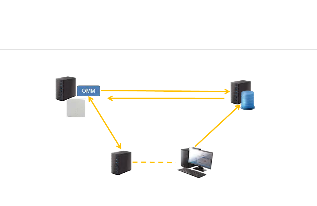
SIP-DECT OM System Manual
250
If the OMM does not find a ConfigURL during initial setup, the OMM contacts the RCS to request a
ConfigURL, using its RFP MAC address. If the RFP MAC Address is configured in the RCS, the RCS
provides a ConfigURL that points to an external provisioning server. The OMM attempts to load all
configuration and resource files from the ConfigURL received from RCS.
Note: The SIP-DECT OMM only uses the ConfigURL from RCS. Other
information provided from RCS is not supported.
The OMM requests information from RCS only if no information has been retrieved from RCS prior to the
request. The response is stored permanently in the OMM. To force a new RCS request, the OMM must
be reset to default settings, through the Discard OMM DB and configuration files or Reset OMM
RFP(s) to factory defaults on restart (see section 5.4.1.15).
7.8.9 CUSTOMER LOGO ON OMM WEB SERVICE
SIP-DECT 6.0 and later supports the integration of a customer-specific logo on the OMM Web service
interface. If a customer_image.png file is available on an external file server, customers can integrate
their own logo into the OMM. This logo is displayed beside the Mitel logo on the top bar.
This image can be imported by:
• configuration of a branding image URL to a file server using OMP (see section 6.5.2.7)
• automatic search for a file named ‘customer_image.png’ on the provisioning server
The branding image is stored permanently in the OMM database, ensuring that the image is available
even if a configured file server or provisioning server is not reachable. The file is deleted automatically
from the server on a “file not found” response or by disabling the branding image URL configuration.
The picture should not be larger than 50 pixels high and 216 pixels wide.
Service Provider
SIP-DECT RCS
1. Registration of
RFP’s MAC
address or
SIP-DECT
System’s PARK
2. OMM inquiry upon start-up
3. Re-direction to Configuration Server
4. SIP-DECT OMM
Configuration

Configuration and Administration
251
7.9 RFP CONFIGURATION FILES
IP-RFPs support two RFP configuration files (downloaded from a server) to get configuration settings.
There is one common file “ipdect.cfg” for all RFPs and one file specific file “<MAC>.cfg” for every IP-
RFP. The RFP requests the “ipdect.cfg” file if a URL is provided. The RFP specific <MAC>.cfg is
requested if this is indicated in the common “ipdect.cfg” file. It is possible that all RFPs request
“ipdect.cfg” and only selected RFPs request the <MAC>.cfg to obtain a specific configuration on some
RFPs.
7.9.1 STANDARD IP SETTINGS
Standard IP settings (which are necessary for access to the RFP configuration files) are configured via
DHCP (see section 7.5) or OM Configurator (see section 7.6). These are:
• IP address
• Net mask
• Gateway (i.e. router)
• Boot file name
• TFTP server
• Public option 224: “OpenMobility” or “OpenMobilitySIP-DECT” (to identify the relevant DHCP offer)
• Domain Name Server (optional)
• Domain Name (optional)
• URL to the RFP configuration files
All other parameters can be set by using an RFP configuration file even if standard DHCP options or OM
Configurator parameters exist.
7.9.2 CONFIGURATION FILE SOURCE
A TFTP / FTP(S) / HTTP(S) URL specifies the protocol, server and path to access the RFP configuration
files. The URL can include account data if appropriate.
Syntax:
{ftp|ftps|http|https}://[user:password@]server/[directory/]
or
tftp://server/[directory/]
The URL configuration is done via DHCP option code 223 (prio1) or DHCP option code 66, or the OM
Configurator.
• “ipdect.cfg” is mandatory if an URL is given by DHCP option code 66 or local static configuration via
the OM Configurator.
• “<MAC>.cfg” is mandatory if it is indicated in the “ipdect.cfg” that a “<MAC>.cfg” exists for the RFP.
(There is a key word to indicate that a “<MAC>.cfg” exists for every RFP.)
Mandatory means that if a file cannot be loaded, the RFP will not start. This is relevant for the following
scenarios:
• RFP boot / startup (after power on, software update, etc)
• a change of the URL

SIP-DECT OM System Manual
252
7.9.3 PARAMETER SETTINGS PRIORITY
Some parameters can be set via DHCP / OM Configurator or by using the files “ipdect.cfg” or
“<MAC>.cfg”. If a parameter is provided through more than one of the possible ways, the last setting has
priority. There is the following order:
• DHCP / OM Configurator
• ipdect.cfg
• <MAC>.cfg
It is also possible to remove settings.
7.9.4 SOFTWARE UPDATE SETTINGS FOR 3RD GENERATION RFPS
A configuration parameter specifies the location of the software that will be installed into the flash of an
RFP 35/36/37 IP / RFP 43 WLAN and activated by the OpenMobility Manager.
OM_SwImageUrl=ftp://172.30.207.21/openmobility/iprfp3G.dnld
TFTP, FTP(S), HTTP(S) are supported for an RFP 35/36/37 IP / RFP 43 WLAN software update.
7.9.5 TIMES WHEN RFP CONFIGURATION TIMES ARE READ
The configuration files are read by the RFP application e.g. during startup as shown in the following
figure.
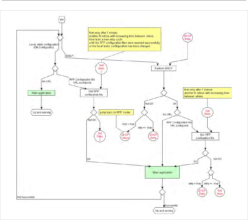
Configuration and Administration
253
Configuration files are read by the RFP application at the following times:
• RFP reboot
• Restart of an application e.g. OMM
• DHCP renew and DHCP bound
• Configuration changes via OM Configurator
• RFP configuration file update check
7.9.6 RFP CONFIGURATION FILE UPDATE CHECK
RFP configuration file update check has the following characteristics:
• The interval is configurable in the RFP configuration files (minimum interval: 5 minutes; maximum
interval: 7 days).
• Default interval: 24 hours.
• Both RFP configuration files are checked if relevant.

SIP-DECT OM System Manual
254
If the configuration file(s) cannot be retrieved …
• The RFP continues operation with the last successfully retrieved configuration file(s).
• The RFP will try to retrieve the configuration files again, starting with an interval of one minute and
doubling this interval with each retry, not exceeding the update check interval (either default or
configured).
• If the RFP is using DHCP, a renewal of the lease is scheduled so that possible changes in DHCP
configuration will be detected.
• Failure to retrieve the configuration files is reported via Syslog.
7.9.7 HANDLING OF PARAMETER CHANGES
A change of a parameter (DHCP / OM Configurator, RFP configuration files) does not necessarily mean
a change to the RFP’s configuration because the parameter could be covered up or previously set using
an alternative way.
Example 1:
IP address of a Syslog Daemon has been changed in “ipdect.cfg” but is covered up by “<MAC>.cfg” in
which this parameter has not been changed.
Example 2:
A parameter is new in “<MAC>.cfg” but has been set previously in “ipdect.cfg” with the same
parameter value.
Only if a parameter change causes a change in RFP configuration (as a sum of e.g. DHCP / OM
Configurator, “ipdect.cfg” and “<MAC>.cfg” files) will the RFP perform a configuration update procedure.
Depending on the changed parameter, an RFP configuration update is done:
• On the fly without any service interruption e.g. IP address of a Syslog Daemon has been changed.
• With an application restart e.g. OMM IP address has been changed.
7.9.8 CONFIGURATION FILE SYNTAX
################################################################################
# sample configuration file for the OpenMobility system
# retrieved via the net using file transfer protocols
# like tftp, ftp, http, https, ftps
#
################################################################################
# comments start with the hash sign: "#"
#
################################################################################
# BOOL variables support the following values
# YES Y 1 TRUE (case does not matter)
# NO N 0 FALSE (case does not matter)
# other values are interpreted as false
#

Configuration and Administration
255
################################################################################
# personal configuration files
#
# personal configuration files have the following name
# <OWN-MAC>.cfg, where <OWN-MAC>.cfg is of the form
# e.g. 003042ABCDEF.cfg
# all RFPs will also load the <OWN-MAC>.cfg file
OM_PersonalConfigAll=1 # BOOL
# DO load the individual file for the RFP with mac 003042FFF0D0
# no matter what OM_PersonalConfigAll says
OM_PersonalConfig_003042FFF0D0=y
# DO NOT load the individual file for the RFP with mac 003042ABCDEF
# no matter what OM_PersonalConfigAll says
OM_PersonalConfig_003042ABCDEF=n # BOOL
# time interval for checking the remote cfg files in seconds
# minimum value is 300 (5 minutes)
# maximum value is 604800 (7 days)
OM_ConfigCheckInterval=500
################################################################################
# OpenMobility system
#
# the OpenMobilityManager ip addresses
OM_ManagerIpAddress1=172.30.205.17
OM_ManagerIpAddress2=172.30.205.18
# path to the software image
OM_SwImageUrl=ftp://172.30.207.21/openmobility/sw/iprfp3G.dnld
################################################################################
# SYSLOG
#
OM_SyslogIpAddress=172.30.207.20
OM_SyslogPort=10115
################################################################################
# transfer core files to the following directory
#
OM_CoreFileSrvUrl=ftp://10.103.35.20/corefiles

SIP-DECT OM System Manual
256
7.10 CONSOLIDATED CERTIFICATE MANAGEMENT
SIP-DECT has various secured interfaces to support secure connections for file imports from local
servers or provisioning servers. By default, the OMM Web server uses the hardcoded self-signed OMM
certificate as local certificate for encrypted AXI connections, for provisioning (mutual authentication), and
for SIP-over-TLS connections.
Certificate and authentication validation settings for these secure connections can be inherited from the
configuration file URL (see section 7.8.1).
7.10.1 SIP OVER TLS CERTIFICATES
SIP over TLS certificates are used for secure SIP connections. The hard coded self-signed OMM
certificate is used by default, however you can import trusted certificates, a local certificate chain and a
private key file (optionally password-protected) via:
• OMP (System -> SIP -> Security tab)
• OMM Web service (System -> SIP -> Security)
• a certificate server (usually running on a Mitel call server)
7.10.2 OMM CERTIFICATE (WEB SERVICE / AXI)
The OMM Web server uses the hard coded self-signed OMM certificate by default as the local certificate
for encrypted AXI connections.
You can overwrite the hard coded OMM certificate by importing a local certificate chain and a private key
file (optionally password-protected) via the OMP (System -> Advanced settings -> OMM Certificate
tab). You can also configure an OMM certificate server (System -> Advanced settings -> OMM
Certificate server tab) to enable provisioning of OMM certificate files.
The OMM certificate will be used for incoming AXI and HTTPS connections to the OMM services. If the
OMM can be reached from the internet by a domain and an appropriate CA certificate has been
imported, no security warnings are displayed in web browsers trusting the CA root certificate.
7.10.3 PROVISIONING CERTIFICATES
Provisioning certificates are used for secure connections to configuration or firmware file servers with
support for mutual authentication (i.e., for FTP, FTPS, and HTTPs protocols).
The OMM uses a trusted certificate chain to validate the server. This is required if the server has no
certificate derived from a trusted CA root certificate, where the OMM uses the Mozilla CA Certificate List.
If no server certificate is available, you can disable the validation against trusted and CA certificates.
By default, the hard-coded self-signed OMM certificate is used for mutual authentication. You can
overwrite the hard coded OMM certificate by importing trusted certificates, a local certificate chain and a
private key file (optionally password-protected) via:
• OMM Web service System -> Provisioning -> Certificates page (see section 5.4.2.5)
• OMP System -> Provisioning -> Provisioning Certificates tab (see section 6.5.5.2)

Configuration and Administration
257
• a provisioning certificate server through OMP System -> Provisioning -> Certificates server tab
(see section 6.5.5.3)
The OMM provides the local certificate chain and the private key to servers requesting mutual
authentication. The private key file may be password protected.
The system credentials can be inherited if specific sources for configuration and resource files are
configured, where the ‘Use common certificate configuration’ option is enabled.
7.10.4 CERTIFICATE VALIDATION
If the HTTPS or FTPS protocol is used to retrieve files from the configured provisioning server, the OMM
validates the server certificates according to the certificate validation settings.
You can configure the certificate validation settings via OMP (System -> Provisioning -> Provisioning
– SSL settings) or the OMM Web service (System -> Provisioning -> Certificates). Certificate
validation settings can also be part of the ConfigURL provided by the RCS or via DHCP.
If you want to use the same validation settings for a specific URL (i.e., other than the configuration file
URL), enable the “Use common certificate configuration” parameter when configuring the URL (unless
the “Import certificates with first connection” parameter is enabled).
7.11 RFP 35/36/37 IP / RFP 43 WLAN SOFTWARE UPDATE
The DECT base station checks several locations for a software update. If found, the software is copied
to the flash memory, leaving the current software intact. After successful installation, the OMM is notified
about the new software. Activation of the software is then managed by the active OMM. DECT base
stations that do not have a connection to the OMM activate and start the software immediately.
Locations for software updates:
• Attached USB mass storage device with a software image iprfp3G.dnld in its root directory. The USB
mass storage device must be formatted using the vfat32 file system.
• If ipdect.cfg supplies the OM_SwImageUrl variable, the URI is used to get the boot image. Please
see section 7.7.7.
• TFTP server, path and file configured using the OM Configurator or via DHCP.
• OMM (SIP-DECT 6.0 or later): If the RFP 35/36/37 IP / RFP 43 WLAN have no valid URL from which
to load the software, they attempt to load the software from the connected OMM. If the OMM is
running on a DECT base station, the RFP OMM delivers the software to the connected base stations.
See section 7.8.7 for more information.
7.12 802.1Q SUPPORT
The IP RFPs support VLANs according to IEEE 802.1Q. VLAN can be administered
• on a per port basis of the LAN switch assuming that the IP RFPs are connected to a single port of a
switched Ethernet environment, or
• by assigning a VLAN ID to the IP RFP matching the VLAN they should operate in.
VLAN tagging has only to be set to IP RFPs’ in the last case. The whole section refers to that case. With
this, also 802.1p priority within Ethernet frames is enabled.

SIP-DECT OM System Manual
258
The scope of the following description is restricted to VLAN tagging and obtaining the VLAN ID. Quality
of Service mechanisms like 802.1p priority and DiffServ are not described in this section.
VLAN implementation notes referring to IP RFPs:
• IP RFPs are not able to support VLAN ID 0 as described later in this section. Any other valid VLAN ID
can be configured.
• If a VLAN ID is configured, all traffic from an IP RFP will be tagged with this VLAN ID.
• The VLAN ID configured for an IP RFP is also used for the OMM running on this IP RFP.
• Once a VLAN ID is set to the IP RFP, incoming frames are only accepted if they are tagged as well.
Therefore the switch port must be configured as a tagged trunk for this VLAN.
• The VLAN configurations can be done using DHCP or the interface for the local static configuration,
the OM Configurator.
• The use of VLAN does influence the boot up process of the IP RFP because the VLAN configuration
takes place during the boot up phase.
• The default setting is not to tag the traffic. 802.1Q tagging is enabled if the VLAN ID is set. If no VLAN
ID is set 802.1Q is disabled.
Why not VLAN ID 0 ?
VLAN ID 0 means that the IP RFP’s traffic belongs to the port/native VLAN. The Ethernet switch port to
which the IP RFP is connected must be configured to accept 802.1Q tagging for this to work and the
switch must interpret VLAN ID 0 as the port/native VLAN ID per the IEEE 802.1Q standard.
The packets from the IP RFP are tagged with VLAN ID 0 and the packets sent to the IP RFP are tagged
with the port/native VLAN ID. This scenario does not work, because the IP RFP supports only one VLAN
ID in both directions. That means the VLAN ID in the receive direction must be the same as the send
direction.
7.12.1 BOOT PHASE OF IP RFPS (DHCP)
Because the IP RFP does not know about VLAN at the beginning of the start up, two DHCP scopes are
required. This applies regardless of the Ethernet switch being used. The following scenario with arbitrary
VLAN Ids’ details the steps an IP RFP would go through in a typical dual-VLAN implementation.
Step A. DHCP scope within the native VLAN:
1 IP RFP boots up and obtains an address on the native VLAN.
2 The data VLAN DHCP option 132 directs the IP RFP to go to voice VLAN.
Step B. DHCP scope within the voice VLAN:
1 IP RFP releases the data VLAN address and obtains an address on the voice VLAN and all other
parameters.
The voice VLAN does not have the DHCP option 132, because an IP RFP already on the voice VLAN
does not need to be directed to go there.
2 IP RFP is operational on the voice VLAN.
If a reboot or power cycle occurs, the IP RFP returns to step A.
If an IP RFP cannot obtain an address on the voice VLAN, due to network or DHCP problems then the
IP RFP falls back automatically to untagged frames (native VLAN).

Configuration and Administration
259
To avoid the DHCP scope within the native VLAN the VLAN ID to be used can be set permanently via
OMC without losing the ability to provide other parameter via DHCP, please see section 7.7.
7.12.2 BOOT PHASE OF IP RFPS (LOCAL CONFIGURATION)
The PC running the OM Configurator must be a member of the native VLAN for the first configuration,
later on within the voice VLAN set.
If a wrong or unknown VLAN ID is set, you can overwrite or read the configuration using no VLAN tag on
the switch port in the first six seconds after the RFP is connected to a power supply / PoE. After six
seconds the RFP applies the local configuration and starts using the parameters.
7.13 INSTALLING OMM IN HOST MODE
In this case, the OMM software must be installed on a PC running Red Hat Enterprise Linux 6 or
CentOS 6. The network parameters with which the OMM works in this mode depend on this PC’s
network configuration.
Once started, OMM works permanently on the PC. In case of fatal error or PC restart, OMM will restart
automatically.
Please note: Check that the versions of the OMM and RFP software on your SIP-DECT
installation are the same.
7.13.1 SYSTEM REQUIREMENTS
The OMM application is a 32-bit/x86 application that can be installed on a 32-bit or 64-bit
(recommended) operating system. The PC-based OMM requires the following configuration:
• Red Hat Enterprise Linux 6 or CentOS 6 operating system
• Server hardware minimum:
- Processor : Dual Core Intel® Xeon® 3065, 2.33GHz, 4MB cache
- Bus 1333 MHz
- Memory : 2GB DDR2 SDRAM 667 MHz
- Hard disk: 80 GB SATA 7200 rpm
- 1 GB/s Ethernet interface
7.13.2 INSTALLING THE OMM SOFTWARE
The OMM software for the Linux Redhat server is provided as a self-extracting executable file (e.g., SIP-
DECT_6.1.bin). This binary file contains two Red Hat packages:
• SIP-DECT-OMM-<SIP-DECT-version>.i586.rpm
OpenMobility Manager software.
• SIP-DECT-HANDSET-<DECT phone-version>.i586.rpm
Software for Mitel 600 DECT phones

SIP-DECT OM System Manual
260
The Mitel 600 DECT phone software can be updated via the Air interface, see section 7.20. A separate
software package can also be provided for specific updates of the DECT phone software.
IMPORTANT : Log in as “root” to install and/or update OMM. If you do not login as root
to open the OMM console, the path to ommconsole is not set. You must enter the
whole path “/usr/sbin/ommconsole” to start the OMM console.
Command syntax
For extraction and automatic standard installation
sh SIP-DECT_<version>.bin
For extraction and automatic standard installation
sh SIP-DECT_<version>.bin -f
For extraction of RFP packages only
sh SIP-DECT_<version>.bin –x
RPM packages can also be installed manually.
For a first OMM type installation
rpm –i SIP-DECT-OMM-<version>.i586.rpm
For an OMM software update (see section 7.14)
rpm –U SIP-DECT-OMM-<version>.i586.rpm
For Mitel 600 DECT phone software installation
rpm –i SIP-DECT-HANDSET-<version>.i586.rpm
To delete a software release
rpm –e SIP-DECT-HANDSET and
rpm –e SIP-DECT-OMM
To check an installed release
rpm –qi SIP-DECT-OMM
or
rpm –qi SIP-DECT- HANDSET
After the installation phase, start OMM by running the command
“/etc/init.d/sip-dect-omm start”
7.13.3 CONFIGURING THE START PARAMETERS
The basic data for initializing OMM is stored in the file “/etc/sysconfig/SIP-DECT”. It can be edited to
modify the OMM interface.
##############################################
# OMM configuration file
##############################################
# if you use a different interface for omm activate/correct parameter below
#OMM_IF="eth0"
#
OMM_CONFIG_FILE=/opt/SIP-DECT/tmp/omm_conf.txt
#
#if you use OMM resiliency for OMM activate parameter below with OMMs IP adresses
#OMM_RESILIENCY="192.168.0.1:192.168.0.2"

Configuration and Administration
261
#
# Automatic OMM database import:
# TFTP / FTP / HTTP(S) URL specifies the import server and file
Parameters Description
OMM_IF Interface for communicating with the RFPs (by default: eth0)
OMM_CONFIG_FILE File that contains the OMM configuration (by default: /opt/SIP-
DECT/tmp/omm_conf.txt)
OMM_RESILIENCY In case of OMM redundancy, enter the two IP addresses of the
OMMs. See also section 7.15.
7.13.4 SPECIFIC COMMANDS – TROUBLESHOOTING
The OMM software is installed but does not work automatically when the PC starts. The command below
stops or starts OMM manually (User root):
/etc/init.d/sip-dect [start|stop|restart].
The command line interface for OMM is accessible via telnet on port 8107.
Malfunction
To check whether OMM is working, see the list of procedures for the “SIP-DECT” process. If OMM does
not start, delete the lock file “/var/lock/subsys/SIP-DECT”.
To delete the OMM configuration remove the OMM configuration file “/opt/SIP-DECT/tmp/omm_conf.txt”
(by default).
7.14 UPDATING THE OMM
The procedures for updating an existing DECT installation with new software depend on
• whether a single OMM or standby OMM installation is used
• whether the OMM is running on an RFP or PC
The OMM “standby” feature is described in section 7.15.
The update mechanism allows an update of the RFPs with minimum impact to DECT services,
especially for installations with a standby OMM.
All RFPs check the availability of a new boot image file automatically when:
• the DHCP lease is refreshed,
• the RFP lost the connection to the OMM,
• one of the service applications running on the RFP must be restarted, and
• an RFP configuration file update check is done (see section 7.7.7).
Please note: Make sure that all configured software sources point to the same software
version, so that the OMM and all RFPs are running the same software version.

SIP-DECT OM System Manual
262
Please note: RFPs without a configured software image URL (via DHCP, OMC or
ipdect.cfg/<mac>.cfg) retrieve their software directly from the OMM. In this case, the RFP
activates the software immediately. This feature is only available with 3G RFPs.
As soon as an RFP detects a new boot image file on the TFTP server (or the software download server
using FTPS or HTTPS), it notifies the OMM. The OMM keeps track when it is safe to restart an RFP in
order to leave the DECT service synchronized.
RFPs scheduled for restart are marked with a yellow sign within the Web service (see section 5.6.1) or in
a separate column within the OM Management Portal (OMP), see section 6.7.1.
Please note: Only software upgrades from the preceding two releases are tested for
upgrade to the current release. Additional steps may be required to upgrade systems with
software that is three or more releases behind the current release.
7.14.1 UPDATING A SINGLE OMM INSTALLATION
In the case of a single OMM installation, a DECT network outage during the update procedure is
unavoidable.
Please note: Updating a single OMM installation results in a DECT network outage during
the update procedure.
For the update, replace the boot image file on the TFTP server(s) with the new one.
OMM in RFP mode
If the OMM is running on an RFP, force the update of this RFP by pressing the Update button on the
System settings web page (see section 5.4.1.16). The RFP checks the boot image file on the TFTP
server and reboots if a new one is found.
OMM in host mode (on Linux server)
If the OMM is running on a dedicated Linux server, install the new software as described in section
7.13.2 on the PC with the command “SIP-DECT_<version>.bin”. This stops the running OMM
automatically and installs the new software. After the installation phase, restart the OMM by executing
the command “/etc/init.d/sip-dect-omm start”.
As soon as the RFPs lose the connection to the OMM (because of the update), the RFPs detects that a
new image file is on the TFTP server and reboot with the new image file.
7.14.2 UPDATING A STANDBY OMM INSTALLATION
Please note: Updating a standby OMM installation causes a switch over between both
OMMs. All active calls will be dropped.
For the update replace the boot image file on the TFTP server(s) with the new one.

Configuration and Administration
263
OMM in RFP mode
Force the update by pressing the Update button on the System settings web page (see section
5.4.1.16). The OMM-RFP checks the boot image file on the TFTP server and initiates an update
procedure, if a new image file has been found.
The automated update procedure performs the following steps:
1 Reboot the RFP residing the standby OMM.
2 Reboot the RFP residing the active OMM which causes a failover to the standby OMM.
3 Reboot all other RFPs that are able to find the new boot image file one by one. This is managed by
the new active OMM.
This procedure reduces the downtime of the SIP-DECT system to a minimum due to the optimized
failover.
Please note: Please be aware that a minimum downtime of the system can only be reached
if the system was in a stable working state when initiating the update and the IP
infrastructure guarantees a fast update of the OMM RFPs (e.g., no 64kbit/s line to
download the SW into the RFP).
OMM in host mode (on Linux server)
For an update with a minimum impact to the DECT service do the following:
1 Replace the boot image file on the TFTP server(s).
2 Manually update the standby OMM.
a) Stop the OMM service.
b) Install the new software.
c) Start the OMM service.
d) Wait at least 30 seconds before you go on with updating the active OMM.
3 Manually update the active OMM.
a) Stop the OMM service.
b) Install the new software.
c) Wait at least 30 seconds.
d) Start the OMM service.
Please note: A one-by-one update of RFPs is not possible if the signaling interface between
the OMM and the RFP has been changed. Please see the release notes delivered with
the software.
To enforce an update of the whole DECT system at once, deactivate / update both OMMs
simultaneously. The RFPs will lost the connection to both OMMs and will automatically restart with the
new boot image file.

SIP-DECT OM System Manual
264
7.15 OMM STANDBY
To perform OMM standby, two OpenMobility Managers must be provided in an OMM network. One
operates as the active OMM, and the other operates as the standby OMM.
In the event that the RFP designated as the OMM fails, the other RFP, designated as the secondary
OMM automatically assumes the role of the OpenMobility Manager.
How OMM Standby works
During system start-up, each RFP retrieves either one (if no standby OMM is configured) or two (if OMM
Standby is configured) OMM IP addresses and both try to connect to each other. The active OMM
serves all connections from RFPs or DECT phones.
During normal operations, both the active and the standby OMM are in contact and monitor each other’s
operational state. They continually exchange their current standby states and the standby OMM receives
a copy of any configuration changes on the active OMM. As long as both OMMs are in contact, their
databases are synchronized automatically.
If the primary OMM fails, the OMM responsibilities are taken over by the standby OMM to maintain
operation. A “No Standby” warning is displayed on the OMM web interface, indicating that there are no
longer two functioning OMMs in the network or cluster. Configuration changes are made unsafely in this
situation.
If the active OMM fails, the inactive OMM recognizes this and begins to act as the active OMM, and
starts the web service.
If the connection between the two OMMs fails, the network or cluster essentially breaks into two
operational parts. The standby OMM becomes the active OMM. At this point, the two OMMs cannot
detect one another and, therefore, cannot synchronize. When the connection between the two OMMs is
re-established, the synchronization of the OMMs forces one OMM to become the standby OMM again.
Once the recently failed OMM returns to service and becomes the inactive OMM, it does not resume the
role of active OMM.
7.15.1 CONFIGURING OMM STANDBY
Each RFP of the DECT system must be configured with two OMM IP addresses. Both OMM addresses
can be either configured via DHCP (see section 7.5.1) or with the OM Configurator (see section 7.6).
7.15.2 FAIL OVER SITUATIONS
Fail over occurs when:
• an OMM error occurs on the active OMM.
• the RFP acting as the active OMM is shut down or rebooted at the SSH console.
• the OMM is rebooted in the web browser menu.
• the active OMM is unreachable.
The standby OMM becomes the active OMM when:
• the configured SIP Proxy/Registrar is reachable.
• the other OMM has a larger IP Address while no OMM is active and both OMMs are in contact with
each other (normally at system startup).
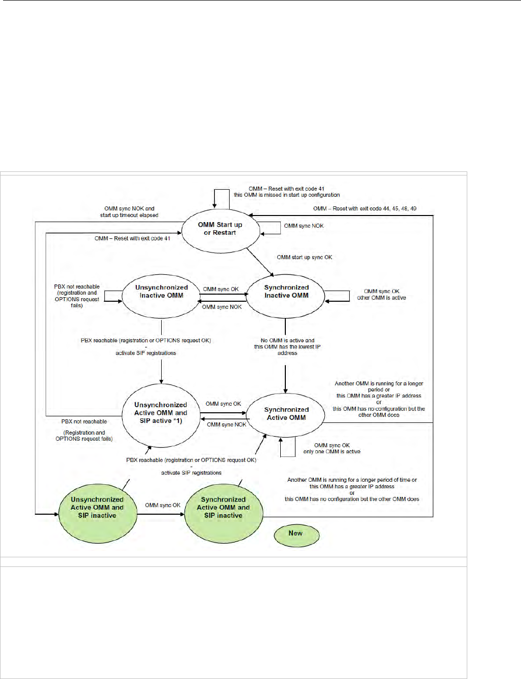
Configuration and Administration
265
When the OMMs get in contact again:
• Both OMMs check which one ran for a longer period. That one will become the active OMM. The
other one falls back to the standby one.
7.15.3 FAILOVER FAILURE SITUATIONS
Failover failure occurs when the connection between OMMs fails and the configured SIP Proxy/Registrar
is unreachable. In this case the active OMM waits until the SIP Proxy/Registrar is reachable.
The following state diagram shows the OMM Standby states:
“OMM sync OK”: OMMs are synchronized and are able to exchange their operational states
“OMM sync NOK”: OMMs are not synchronized and are not able to exchange their operational states
*1) In this state the DECT air interface might not be in a definite state as both OMMs are active but cannot
connect with each other! This is caused by IP network failures and cannot be handled by the SIP-DECT system in
a proper automatic way. In such a scenario it is not predetermined which RFP connects with which of the 2
OMMs. The DECT network can split-up into two unsynchronized DECT sub-networks. This can cause voice
quality and handover problems.

SIP-DECT OM System Manual
266
With these states (“… SIP inactive”) the OMM standby mechanism takes care in the start up phase that
all SIP users does not become active if the PBX is not reachable. This avoids a possible double SIP
registration when the PBX and the other OMM is reachable again before both OMMs negotiate which
OMM becomes the active one.
The double SIP registrations might cause a user not to be reachable when his latest SIP registration
came from that OMM that was negotiated to be the inactive one and the SIP registrar cannot handle two
or more simultaneous registrations (non-forking proxy).
Similarly, it could happen in rare cases that both OMMs become temporarily active. In such a situation all
SIP-DECT users would be SIP registered from both OMMs to the configured PBX. This can cause
problems, if the PBX accepts only one registration per user (non-forking proxy).
To prevent such problems a mechanism is implemented to detect situations with two active OMMs. If
such a situation is detected the remaining active OMM SIP re-registers all users to the PBX if the OMM
SIP reRegister after 2 active OMM failover parameter is set (see section 5.4.3.6).
7.15.4 SPECIFIC STANDBY SITUATIONS
Some aspects must be described in case of OMM state changes when they are unsynchronized.
7.15.4.1 How a standby OMM becomes active
In an unsynchronized OMM state, the standby OMM must decide whether to become active or not.
The OMM tries to contact the configured SIP proxy and registrar. If a specific user account has not been
designated to use for visibility checks (see section 7.20.7), the OMM starts a SIP registration for the
DECT phone with the lowest phone number and sends an OPTIONS request to the configured proxy. If
there is an answer the SIP proxy/registrar is considered reachable and the OMM becomes active.
7.15.4.2 When OMMs are not synchronized
In an unsynchronized OMM Standby state, the connection between the OMMs is broken. In case of a
network problem, both OMMs might be in this state. During this time an inconsistent OpenMobility
system is operational with some constraints.
The OMM Web service issues a warning with the message “No Standby” for both OMMs and it is
possible that configuration changes made are not saved.
When both OMMs are in contact again, the longer running OMM becomes the active OMM and
overwrites the database file in the standby OMM. Configuration changes made in this OMM instance are
lost.
7.15.4.3 Two DECT air interfaces
When both OMMs are in an unsynchronized and active state, they are fully operational. DECT base
stations that lose their connection to the OMM because of a network outage might connect to the other
OMM. Two DECT air interfaces are present and work in parallel.
Note: Since both air interfaces use the same PARK, it is impossible to
determine on which OMM a location registration succeeds.
For DECT phones different situations are possible:
• They do not notice this situation:

Configuration and Administration
267
- active calls stay established, depending on network conditions;
- DECT phones can make and receive new calls, depending on an available PBX connection;
- DECT phones can do handover to RFPs connected to the same OMM;
- DECT phones can call DECT phones that are registered to the other OMM
• They lose their RFP base station and perform a new location registration:
- active calls are broken;
- DECT phones can make and receive new calls, depending on an available PBX connection;
- DECT phones can do handover to RFPs connected to the same OMM;
- DECT phones can call DECT phones that are registered to the other OMM;
• They lose their RFP base station and search the DECT network without finding another one:
- active calls are broken;
- DECT phones stay in searching for network until an air interface is available again.
Note: Handover between DECT phones located to RFPs that are
controlled by different OMMs is not possible.
When the OMMs are in contact again, the inconsistencies are resolved.
7.16 USER DATA SYNCHRONIZATION (MIVOICE 5000 DUAL
HOMING SUPPORT)
SIP-DECT 6.1 introduces support for user data synchronization to ensure that SIP-DECT telephony
services survive if the network connection to the OMM goes down. The feature ensures user and device
database redundancy among all OMM instances in the system.
When user data synchronization is enabled on an OMM instance, the OMM propagates changes in user,
device, Configuration over Air (CoA) profiles or SARI configuration to a central OMM. AXI is used to
distribute configuration changes between the central and peripheral OMMs.
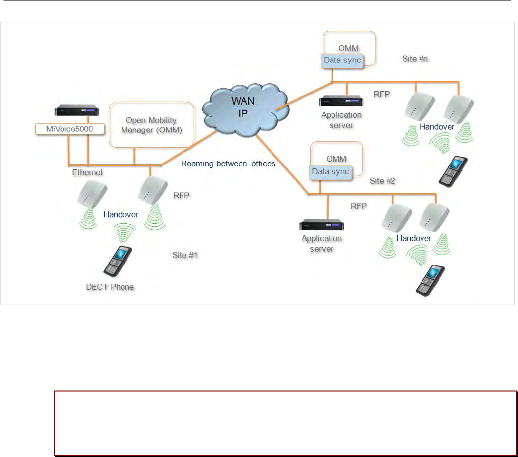
SIP-DECT OM System Manual
268
Instead of subscribing to the standard Primary Access Rights Key (PARK) of a single OMM when
registering with the system, the DECT phones subscribe using the Secondary Access Rights Identifier
(SARI) that applies to multiple OMMs in the system. All DECT phones that are subscribed to the system
using the SARI can roam between sites (and OMMs). The PARK of the central OMM is defined to be the
SARI.
Please note: Subscription to the SARI and successful roaming is only supported for Mitel
600 DECT phones. Behavior of third party GAP phones is not guaranteed. It is
recommended that you add 3rd party GAP phones as fixed devices and configure them to
subscribe to the “PARI only”. See section 6.10.4.5 for more information.
All DECT phone users are registered to a central SIP proxy, used by all OMM sites (as long as the
network environment is stable). OMM sites may implement local secondary SIP proxies, where local
DECT phones register in case of a failed network connection.
7.16.1 ROAMING
The following sections describe the roaming concepts supported with the user data synchronization
feature.
7.16.1.1 Device roaming
All DECT phones that subscribe successfully to the system SARI can roam between sites. Subscription
to the system SARI is enabled by default when a DECT phone is created. SIP registration is renewed
automatically with the OMM at the new site so that users can make and receive calls from all sites.
Unbound devices can also roam, but they are not SIP registered.

Configuration and Administration
269
7.16.1.2 User roaming
Users with existing DECT phones can go to another site and log into an unbound DECT phone. The
login to the old DECT phone is removed, and when the SIP registration is renewed, the DECT phone is
registered with the OMM at the new site, so that the user can make and receive calls from there.
7.16.1.3 Move of SIP registration
The SIP registration follows the user's location, according to the following rules:
• When the change in site location is detected, the new OMM initiates a SIP registration.
• All other OMM sites are notified of the change, such that the OMM for the previous site does not
renew the DECT phone SIP registration and broadcasts the change to all other OMMs.
• When the new OMM receives the update from the previous OMM, the SIP registration is repeated.
If there is any interruption in the user data synchronization, other OMMs are not notified of the
change. In this case, the OMM at the new site initiates a SIP registration a soon as the change in site is
detected. If the OMM does not receive an update within 30 seconds, the new OMM renews the SIP
registration anyway.
When user data synchronization is restored, the appropriate notifications resume:
• The previous OMM does not renew SIP registration for the DECT phone and broadcasts the
information to all other OMMs.
• The OMM at the new site repeats the SIP registration when the update is received.
Please note: If the OMM hosting an active Mitel DECT phone does not receive an updated
location registration for the device for more than two hours, the OMM does not renew the
SIP registration until the location registration is refreshed.
7.16.2 SETTING UP USER DATA SYNCHRONIZATION
Data synchronization is only implemented for user, DECT phone, and Configuration over Air (CoA) data.
The SARI is copied from the central OMM to the peripheral OMMs. All other data must be configured on
each OMM individually. If there are any configuration conflicts due to network connection failure, the user
and device changes (that have the same key id) with the most recent time stamp are used.
To set up user data synchronization for your SIP-DECT system, you must:
• define the central OMM and generate a SARI for all OMMs to use when registering to the system
• configure links to the central OMM from every peripheral OMM in the system
• create a dedicated user account to verify standby OMM availability
7.16.2.1 Defining the central OMM
You must select an OMM to act as the central OMM for user data synchronization. When you have
selected the OMM, generate the SARI from the OMM's PARK value (via the OMP System -> Basic
settings -> DECT tab). See section 6.5.1.2 for configuration details.
All Mitel 600 DECT phones registered with the OMM can then roam to all other OMM sites (which may
be added later).

SIP-DECT OM System Manual
270
7.16.2.2 Configuring links to the the central OMM
Each peripheral OMM in the system must connect to the AXI interface of the central OMM for user data
synchronization. If a standby configuration is used for the central system, both OMMs must be
configured in the peripheral OMMs. You configure the connection to the central OMM via the OMP
System -> Data management -> DECT phones synchronization tab (see section 6.5.7.3 for
configuration details).
Before you link a peripheral OMM to the central OMM, you must delete all user and device data, and
CoA profiles from the local OMM. After the connection is established, verify that the user and device
data from the central OMM have been received, then reconfigure the deleted users and devices.
Please note: Concurrent configuration of user and device data may cause conficts. This
can happen if one or more OMMs are not visible due to network issues. If conflicts are
detect for user or devices with the same key Id, those with the most recent timestamp are
kept.
SIP-DECT provisioning mechanisms ensure that there are no conflicts with user data synchronization.
However, the system cannot regulate operations such as "auto-create on subscription". Under rare
circumstances, conflicts can arise with the result that a user action may be ignored. Repeat the action to
ensure it is registered by the system.
You must also ensure that the calling party numbers do not conflict with any conference room, FAC
prefix or alarm trigger number across all OMMs in the system.
Please note: The user data synchronisation mechanism does not validate conference room,
FAC prefix or alarm trigger numbers. If such numbers conflict with a user's calling number,
synchronisation terminates immediately.
7.16.2.3 Creating a user account for standby visibility checks
If the active or standby OMM loses connectivity, each OMM checks connectivity to the SIP proxy. By
default, a real SIP user account is used to check the availability of the OMM (via a SIP registration to the
SIP proxy). In a dual homing environment, this may impact the user’s telephony services due to the data
synchronization.
To avoid this issue, you must create a virtual SIP user to be used exclusively for checking OMM
availability (one account for the entire system). See 7.20.7 for more information on this feature.
7.16.3 USER DATA SYNCHRONIZATION MODES
The user/device synchronization runs on every peripheral OMM with a configured link to the central
OMM. The synchronization function requires an internal AXI connection and an external AXI connection
to the central OMM.
There are two synchronization modes: system startup or reconnection to resolve conflicts and copy new
or changed datasets, and dynamic synchronization mode.
7.16.3.1 Start-up / reconnection mode
In start-up/reconnection mode, the user data synchronization service reconciles the data in the
peripheral OMMs and central OMM. The steps in the user data synchronization mechanism are:

Configuration and Administration
271
1 Read user/device data and profiles from internal AXI.
2 Read SARI from external AXI.
3 Set SARI on internal AXI.
4 Read user/device data and profiles from external AXI.
5 Resolve conflicts.
- Inconsistent associations (one device bound to two different users): association is deleted on the
system with the older user/device timestamps. An unbound user remains.
- Inconsistent number (two different user datasets using the same number): the user with the older
timestamp is deleted (including any existing device associations)
- Inconsistent additional ID (two different user datasets with the same additional ID): the user with
the older timestamp is deleted (including any existing device associations)
- Inconsistent association (one user bound to two different devices): association is deleted on the
system with older user/device timestamps. An unbound device may remain if an IPEI was
configured, otherwise the device is deleted.
- Inconsistent IPEI (two different device datasets with the same IPEI): the device with the older
timestamp is deleted (including any existing user associations)
6 Copy data.
Data with the most recent timestamp is copied to either the peripheral OMM (if data in the central
OMM is more recent) or the central OMM (if data in the peripheral OMM is more recent), including:
- profile datasets with newer timestamps
- changed users with newer timestamps (with the device dataset, if bound)
- new users (with the device dataset, if bound)
- changed unbound devices with newer timestamps
- new unbound devices
7.16.3.2 Dynamic mode
In dynamic synchronization mode, events related to new, changed, or deleted users/devices received
from one OMM are applied on the other OMM.
In rare cases, when configuration changes are made on multiple OMMs simultaneously (e.g. by
configuration via OMP/Web, login/logout on devices, auto-create on subscription, etc), thereby creating
new conflicts, the user data synchronization service closes the AXI connections and restarts after a
minute to initiate a new synchronization.
7.17 MANAGING ACCOUNT DATA FOR SYSTEM ACCESS
Each RFP provides different independent access types:
• the OMM Web service/HTTPS interface (see section 5);
• the OMP (see section 6);
The OMM Web service and the OMP are mainly used for configuration and administration.
• the OM Configurator (see section 7.6);
The OM Configurator is mainly used for static local configuration of an RFP.
• the SSH user shell (see section 8.3.5).
The SSH user shell is mainly used from experts for diagnosis.

SIP-DECT OM System Manual
272
Each of this these access types uses the same account data.
The account data can be altered at the User account page of the OMM Web.
The OMM delivers all the necessary account data to all connected RFPs. The RFPs save the account
data inside their permanent memory. This has some implications:
• An RFP out of the box uses the default account data as long as this RFP is not connected to the
OMM.
• An RFP which was connected for at least one time with the OMM uses the account data from the
OMM.
• When the account data are changed on the OMM, any not connected RFPs will continue to use the
older passwords.
7.17.1 ACCOUNT TYPES
There are three different account types:
• Full access: This access type is the “normal” access for the configuration. Using this access it is
allowed to configure the OMM and each RFP. On the SSH interface of an RFP this access type
allows login for debug information e. g. “pinging” another RFP to check visibility.
The factory setting for this account is
Name: 'omm'
Password: 'omm'
Active: 'n/a'
• Read-only access: As the name suggests this access type is not allowed to configure any item of the
OMM installation. This access type can only be used on the OM Web service. The account can be
deactivated.
The factory setting for this account is
Name: 'user'
Password: 'user'
Active: 'yes
• Root (SSH only) access: This access type is only applicable on the SSH interface of an RFP. Its
purpose is to get detailed information e. g. parameters from the kernel. The access using this account
type is not reachable from other hosts hence a login using the full access type is necessary.
The factory setting for this account is
Name: 'root'
Password: '22222'
Active: 'n/a'
Please note: It is highly recommended not to use the “Root (SSH only) access” account
type. It is meant for technical support only.
7.17.2 POTENTIAL PITFALLS
When an RFP is configured via the OM Configurator and is taken out of an installation, the RFP may
become unusable:
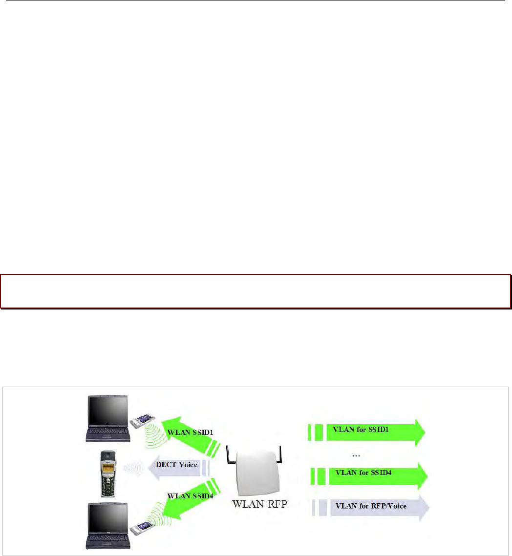
Configuration and Administration
273
• When this RFP comes up, it finds a valid configuration in its permanent memory. It will hence skip
DHCP for booting.
• But when this configuration is not valid anymore (e.g. the TFTP server has a new IP address
meanwhile), the RFP isn't able to complete the boot and is hence not able to connect to the OMM.
• The RFP will not get newer passwords from the OMM.
It is therefore recommended to switch of the OM Configurator before taking an RFP out of an installation.
But nevertheless the OM Configurator allows to reset the permanent memory of an RFP (the Mitel
support must be connected).
7.18 WLAN CONFIGURATION (RFP 42 WLAN / RFP 43 WLAN ONLY)
7.18.1 WLAN CONFIGURATION STEPS
The correct configuration of an RFP with a WLAN interface requires the correct configuration of the
DECT part. The second step is to specify the Regulatory domain of the WLAN network at the System
settings page of the OMM web service (see section 5.4.1.3).
WARNING: Please note that selecting the incorrect regulatory domain may result in a violation
of applicable law in your country!
Select one of the two-letter country codes. This setting depends on the country and is prescribed by the
laws of that country. Only the setting prescribed for that country must be used.
The third step is to specify the WLAN parameters in a profile (see section 5.8.1). The WLAN profile
determines the name (SSID) of the WLAN network and other parameters. The encryption and
authentication procedures are especially important and must be planned carefully beforehand.
The access point can be assigned to a VLAN that conforms to 802.1q. All the data that is received from
and that is to be forwarded to the WLAN clients is then carried by the configured VLAN. All other data,
such as VoIP packets, configuration data or authentication data (Radius), is given the VLAN tag
configured for the RFP. The switch port of the network component to which the access point is
connected must be configured as a trunk port.
Note: The RFP 42 WLAN and RFP 43 WLAN must be connected at
least via a 100BaseT Ethernet link in order to activate the RFP’s
WLAN function.

SIP-DECT OM System Manual
274
As a forth step, you must assign a WLAN profile to a configured RFP. This can be done on the DECT
base stations page of the OMM web service or on the OMP DECT base stations -> Device list page.
Note that specific radio settings for the RFP, such the channel-, 802.11abgn mode-, or antenna settings,
are also done in this step.
7.18.2 OPTIMIZING THE WLAN
Beacon Interval
Transmitting beacons requires transmission channel capacity. A shorted beacon interval increases the
WLAN network's ability to detect signals, thus improving its availability. At the same time, it increases the
network's ability to adjust the mutually negotiated signal strength. A longer beacon interval saves WLAN
air time and also reduces the power consumption of mobile WLAN clients.
RTS Threshold
If the network throughput is low or if many retransmissions occur, the RTS/CTS handshake can be
activated by reducing the RTS threshold value below 1500 byte. This can improve throughput, especially
in environments where reflection and attenuation cause problems for HF.
Fragmentation Threshold
In environments where there is lot of interference and poor radio quality, reducing the fragment size
below 1500 bytes can improve the effective throughput. However, transmitted data frames must be
fragmented, which means a higher load on the RFP’s processor.
DTIM Period
The DTIM period specifies the interval between transmissions of the broadcast and multicast packets. All
WLAN clients must be active during this interval. Increasing the DTIM period lowers the client’s power
consumption slightly. Not all programs can manage the increase in response times, however.
Channel Allocation
Every WLAN RFP must be configured to a channel. You should ensure that the channel settings do not
overlap. WLAN RFPs within range of each other should be configured at least five channels apart. When
the radio field is planned, the WLAN RFPs of foreign WLANs that may be operating in the vicinity must
be taken into account.
When planning the radio coverage for a two-dimensional area, please bear in mind that the distance
between any two base stations operating on the same frequency must be at least twice their range. The
range can be adjusted by lowering the output power level.

Configuration and Administration
275
802.11i: WPA2-Enterprise Pre-Authentication for fast Roaming
WLAN stations (e.g. laptop) which decide to roam to another WLAN access point (AP) must perform the
full authentication process with the new AP. In 802.1X (RADIUS) networks this can take a long time
resulting in network dropouts during the roam.
The AP share authentication information with other APs, so the station can authenticate faster (pre-auth)
when roaming to a new AP. This method reduces network dropouts significantly.
The RFP43 automatically enables pre-authentication for WPA-Enterprise enabled WLANs. The RFP42
does not support this feature.
Channel Configuration Feedback for HT40 and Transmit Power
The HT40 channel configuration in 802.11n enabled networks may not always become active because of
other access points that use channels that would overlap. In this case, the RFP43 will fall back to HT20.
The effective channel configuration and the transmit power are reported to the OpenMobility Manager.
Users can inspect these parameters using the WEB interface and the OMP and may change the channel
to a frequency without overlapping APs.
7.18.3 SECURING THE WLAN
In order to ensure that communication in the WLAN network is secure, several measures must be taken.
Firstly, data packets transmitted via the openly visible radio interface must be encrypted, and secondly,
all WLAN components that provide services must authenticate themselves.
There are different encryption methods available that you configure within the WLAN profile (see section
5.8.1). However, only the recent WiFi protected access (WPA) encryption offers sufficient security
against possible intruders. You should not use the (older) WEP encryption for your company LAN.
Especially with larger WLAN installations, the single shared secret offered by WPA-personal may not be
sufficient for your security requirements, because any person that connects to the WLAN needs to know
the same shared secret. For this reason, you should also setup RADIUS authentication that is supported
by all RFP 42 WLAN and RFP 43 WLAN devices.
A Radius Server (Remote Authentication Dial In User Service) handles 802.1x Authentication, thus
authorizing different WLAN clients with an individual username / password combination to log in. We
recommend a Radius Server with EAP-TLS (e.g. FreeRadius or MS Windows 2003 IAS Server) and a
Certificate Authority (CA).
The RADIUS authentication takes place between the RADIUS server and the RADIUS client, with the
WLAN RFP to pass-through this communication. You should refer to the documentation that comes with
your RADIUS product for details on how to setup, maintain and operate the RADIUS system.

SIP-DECT OM System Manual
276
7.19 SNMP CONFIGURATION
To manage a larger RFP network, an SNMP agent is provided for each RFP. This will give alarm
information and allow an SNMP management system (such as “HP Open View”) to manage this network.
The SNMP agents can be configured in the SNMP menu of the OM Web service (see section 5.4.6).
All SNMP agents are configured by the OMM. Additional parameters that are valid for the individual RFP
(e.g. “sysLocation” and “sysName”) are generated. The “sysLocation” parameter corresponds to the
location configured via the OMM web interface. The “sysName” parameter is generated using the MAC
address and the RFP device type (e.g. RFP 43 WLAN). The RFP uptime can be requested by reading
the “sysUpTime” parameter. This value indicates how long the RFP application software is running. It
does not indicate the uptime of the operating system which does not correspond to the operational RFP
state.
The SNMP agent responds to SNMPv1-read and SNMPv2c-read requests for the standard MIB-II
objects. The Management Information Base (MIB-II) contains 11 object groups. The agent receives both
SNMPv1 and SNMPv2c traps. It sends a “coldStart” trap when it first starts up. It also sends an
enterprise-specific trap “nsNotifyShutdown” when it stops. When the SNMP agent receives an SNMP
request using an unknown community name, it sends an “authenticationFailure” trap. The SNMP agent
also generates an enterprise-specific trap “nsNotifyRestart” (rather than the standard “coldStart” or
“warmStart” traps) after being reconfigured.
7.20 BACKUP SIP PROXY/REGISTRAR
This section provides an overview about the supported redundancy concepts with SIP-DECT to realize a
high availability solution together with IPBX redundancy mechanism.
The focus of this section is IPBX redundancy. For information regarding OMM redundancy, see section
7.15.
7.20.1 REGISTER REDIRECT
To allow IPBX systems to spread the registration and call traffic over different servers the OMM supports
301 (Moved Permanently) or 302 (Moved Temporarily) responses for registrations.
When a 301 or 302 response is received, the OMM follows the redirect and registers the concerning user
to the given address. If more than one contact address are given in the 301/302 response, the OMM
tries to contact the registrars successively until the registration succeeds.
If the redirected register succeeds and if the configured proxy and registrar are identical, all subsequent
INVITE requests are sent to the redirected server. In the other case all subsequent INVITE requests will
be sent to the (outbound) proxy or secondary/tertiary (outbound) proxy.
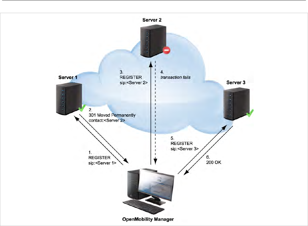
Configuration and Administration
277
7.20.2 DNS SRV
If a full qualified domain name is configured as proxy, outbound proxy or registrar server and the
respective port setting is set to zero (“0”), the OMM performs a DNS SRV query before an appropriate
SIP transaction is started. Herewith the OMM locates a list of servers responsible for the given SIP
domain. With this configuration, the default port (“5060”) is used for every server address acquired with
this mechanism.
The DNS SRV results are sorted by priority and weight in ascending order by the OMM. As soon as the
DNS SRV query succeeds, the OMM starts the appropriate SIP transaction by sending the request to the
server with the uppermost priority and weight of the DNS SRV result.
If there is no answer from the first SIP server in a configurable time frame (“Transaction Timer”
parameter), it will be assumed as unreachable and the OMM tries to contact the next server of the DNS
SRV result. Therefore the request will be send to the second server of the DNS SRV query result. If
there is also no answer in the given time frame from the second server, the request will be send to the
third server and so on. When there is an answer from one of the contacted servers, this server will be
used for this transaction.
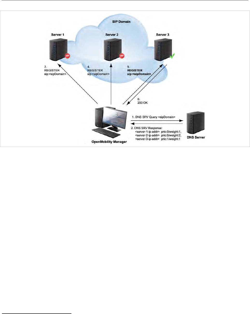
SIP-DECT OM System Manual
278
To prevent situations where the OMM tries to contact with each new transaction servers which are
unreachable (out of service), the OMM offers a blacklist feature. If there is no answer from a SIP server,
this specific server can be put into a blacklist and will not be contacted anymore for a configurable time
of “Blacklist time out” minutes by all adjacent SIP transactions.
In differentiation to the concepts described in the following sections note that independent of which SIP
server is used, all requests send by the OMM carry the same sender Address-of-Record (AOR)1. This
means that the sender URI consisting of user-ID and domain is not changed during a failover to another
server.
7.20.3 BACKUP SIP SERVERS
The SIP-DECT solution allows configuration of two additional levels of backup servers, in addition to the
primary proxy, outbound proxy and registrar server. These two additional levels of backup servers are
referred to as secondary and tertiary servers in the following sections.
1 RFC 3261: An address-of-record (AOR) is a SIP or SIPS URI that points to a domain with a location
service that can map the URI to another URI where the user might be available. Typically, the location
service is populated through registrations. An AOR is frequently thought of as the “public address” of the
user.
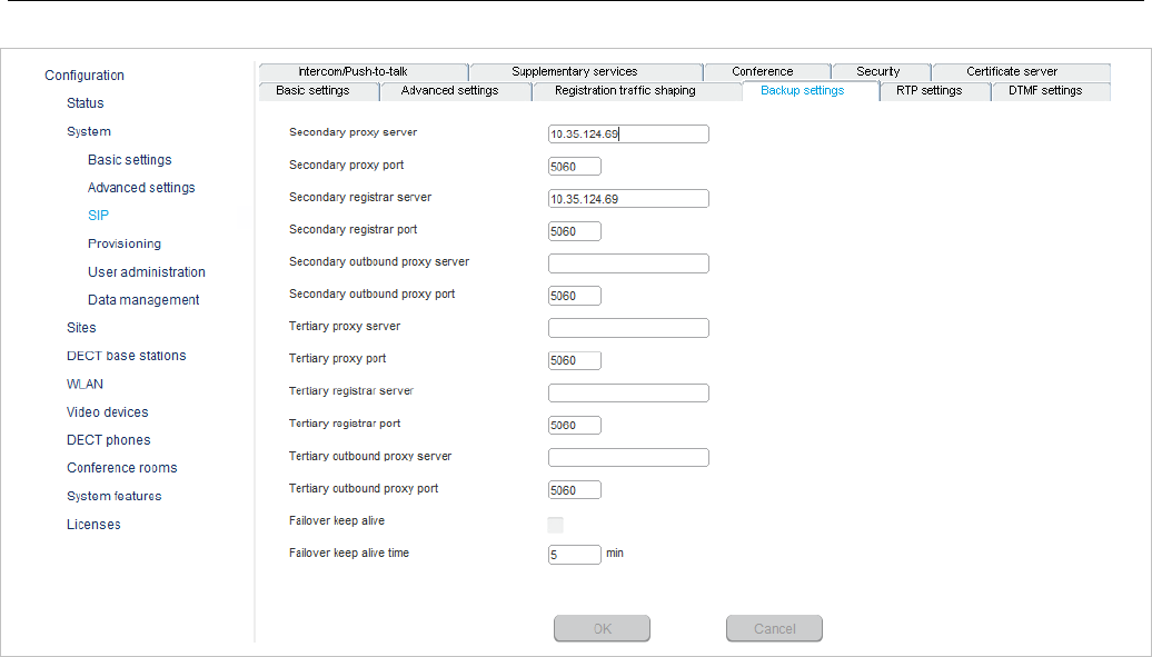
Configuration and Administration
279
SIP backup servers can be configured in the System -> SIP menu of the OM Management Portal
(OMP), see also section 6.5.4.
You can configure IP addresses, names or full qualified domain names as server addresses. It is also
possible to configure a mixture of IP addresses, names or full qualified domain names for the different
servers.
If fully qualified domain names are configured and the respective port setting is configured to zero (“0”),
DNS SRV queries are performed to locate a list of servers in the domain. It is assumed that all server
addresses are specified by name or IP address. With fully qualified domain names, the behavior
described in section 7.20.2 is performed in addition to contact the SIP servers in the given domain.
This redundancy mechanism is based on a failover concept where the OMM first tries to contact the
primary server. If the primary server fails, the OMM tries to contact the secondary server and if the
secondary server fails also, the OMM tries to contact the tertiary server.
The OMM failover behavior in detail depends on the backup server settings.
7.20.3.1 No Secondary/Tertiary Proxy, Outbound Proxy and Registrar Configured
In this case is no failover to a secondary/tertiary (outbound) proxy / registrar is possible.
7.20.3.2 Secondary/Tertiary Proxy and Registrar Configured
All REGISTER and re-REGISTER requests attempt to use the primary registrar first.
If the primary registrar fails (e.g. no answer in “transaction timer” time frame), the user is tried to register
with the secondary/tertiary registrar using as AOR the secondary/tertiary proxy address.
When the registration with the secondary/tertiary registrar succeeds:
• the MWI subscription is moved to the secondary/tertiary proxy,
• all subsequent INVITE requests attempt to use the secondary/tertiary proxy,
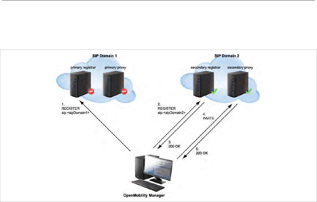
SIP-DECT OM System Manual
280
• the registration of all other users currently registered with the failed server will be automatically
refreshed if the “Failover keep alive” setting is enabled (see page 143). For this purpose, the re-
register requests will be queued and proceed according to the settings for “Registration traffic
shaping” (see section 5.4.3.5).
If a user was registered successfully with the secondary/tertiary registrar and can be registered again
with the primary registrar e.g. during a re-registration:
• the MWI subscription is moved back to the primary (outbound) proxy,
• all subsequent INVITE requests attempt to use the primary (outbound) proxy again,
• the registration of all other users currently registered with the secondary/tertiary registrar will be
automatically refreshed.
As long as no successful registration exists, all INVITE requests attempt to use the primary (outbound)
proxy as first.
If the INVITE request to the primary proxy fails, the INVITE request attempts to use the
secondary/tertiary proxy. If an INVITE request fails (no answer in “transaction timer” time frame) send to
a proxy identical with own registrar, the registration will be refreshed.
7.20.3.3 Secondary/Tertiary Proxy, Registrar and Outbound Proxy Configured
In this case, the OMM behavior is as described in section 7.20.3.2 but all requests for the
secondary/tertiary proxy/registrar are sent through the outbound proxy.
7.20.3.4 Secondary/Tertiary Proxy Configured Only
All REGISTER, INVITE and SUBSCRIBE requests attempt to use the primary proxy or registrar first.
If an INVITE/SUBSCRIBE request fails, the INVITE/SUBSCRIBE request attempts to use the
secondary/tertiary proxy.

Configuration and Administration
281
7.20.3.5 Secondary/Tertiary Outbound Proxy Configured Only
The OMM behavior is as described in section 7.20.3.2 but
• all requests for the secondary/tertiary proxy/registrar are send through the outbound proxy;
• if the registration with the primary registrar fails, the registration is re-tried using the primary proxy
address as AOR sent through the outbound proxy.
•
7.20.3.6 Secondary/Tertiary Registrar Configured Only
All REGISTER, INVITE and SUBSCRIBE requests attempt to use the primary proxy or registrar first.
If a REGISTER request fails, the request attempts to use the secondary/tertiary registrar.
7.20.4 KEEP ALIVE MECHANISM
A keep-alive mechanism implemented in the OMM allows the automatic failover to secondary/tertiary
servers or automatic coming back to primary servers. The keep-alive mechanism is based on the
registration process and utilizes the special behavior that all REGISTER and re-REGISTER requests are
sent to the primary registrar first.
The following configuration parameters are introduced: Failover keep alive and Failover keep alive
time. These parameters are set in the OM Management Portal (OMP) on the Backup settings tab of
the System: SIP menu (see page 143).
For each registration target, a user could be registered successful with, a keep alive procedure is
started. For this purpose the first user registered successful on a registration target will be selected to re-
register all “Failover keep alive time” before the registration period expires.
If the re-registration of this selected user detects that the current primary server fails, the registration of
all users registered on the same server will be refreshed automatically. For this purpose the re-register
requests are queued and proceed according to the registration traffic settings (see section 5.4.3.5 for
OMM Web or section 6.5.4.3 for OMP).
If the re-registration of a selected user detects that the primary server is available again, the registration
of all users registered on a secondary/tertiary registrar will be refreshed.
7.20.5 PRIORITIZED REGISTRATION
Depending on the settings for “Registration traffic shaping”, the registration of a high number of users
could need minutes. In effect single users could not be reachable for minutes during startup.
To guarantee a minimum blackout for very important people (e.g. emergency user) the registration of
such people can be prioritized. Therefore a special user attribute VIP (very important person) is
introduced. The corresponding option is set in the SIP tab of the DECT phone Detail Panel (see page
188).
7.20.6 MONITORING THE SIP REGISTRATION STATUS
The SIP registration status of a DECT phone user can be monitored by using the OpenMobility
Management Portal (OMP). In OMP monitor mode you can view on which registrar a specific DECT

SIP-DECT OM System Manual
282
phone user is registered and whether the server is a primary, secondary or tertiary server. To monitor
the SIP registration status proceed as follows:
1 Launch the OMP (see section 6.1) and navigate to the DECT Phones -> Overview menu.
2 Switch to Monitor Mode.
3 Activate the Registered, Registrar server type, Registrar server and Registrar port columns (see
section 6.10.9).
7.20.7 CONFIGURABLE USER ACCOUNT FOR STANDBY CHECK
The “Standby OMM” feature of SIP-DECT allows configuration of the user account to be used to check
iPBX availability. Such an availability check starts automatically in fail over situations.
Therefore, the OMM starts a SIP registration for a specific DECT phone user and sends an OPTIONS
request to the configured SIP proxy. If there is an answer, the SIP proxy/registrar is considered
reachable and the standby OMM becomes active.
With older SIP-DECT releases, the OMM used the user account with the lowest phone number for the
check procedure.
To select a specific user account for this purpose, enable the Used for visibility checks flag on the SIP
tab when creating or editing a DECT phone.
Please note: The “Used for visibility checks” flag can only be set for one user. The number
for visibility checks is shown in the OMP under Status -> Users -> Number.
If the flag is not set for a specific user, the OMM uses the user account with the lowest
phone number.
7.20.8 OMM STANDBY ENHANCEMENT
With SIP-DECT systems using the OMM standby feature it could happen in rare cases that both OMMs
become temporarily active. In such a situation all SIP-DECT users were SIP registered from both OMMs
to the configured PBX. This can cause problems, when the PBX accepts only one registration per user
(non-forking proxy).
To prevent such problems a mechanism is realized to detect situations with two active OMMs. When
such a situation is detected the remaining active OMM will SIP re-register all users to the PBX.
This mechanism can be enabled/disabled via the OMP SIP->Supplementary Services tab (see section
6.5.4.8).
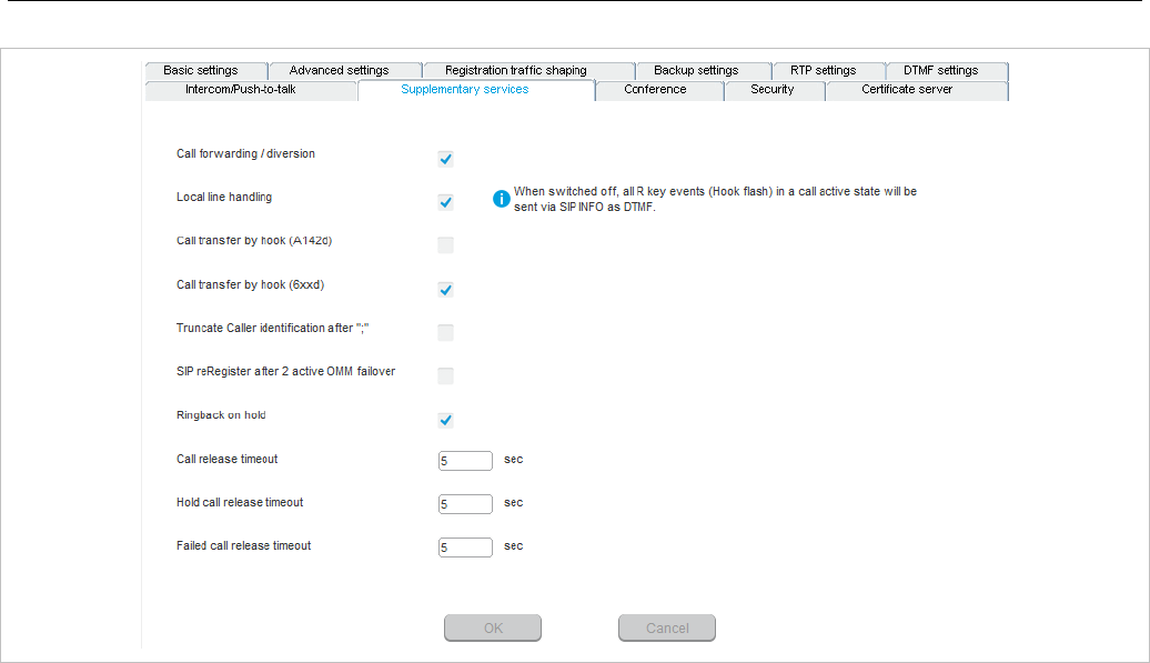
Configuration and Administration
283
7.21 CONFERENCING
Depending on the type of conference server used, SIP-DECT offers the following operational modes:
• None: neither external nor internal conference server is used.
• Integrated: the conference server integrated in SIP-DECT is used.
• External: an external conference server is used, e.g. Broadsoft or Sylantro.
• External – Blind Transfer: a MiVoice Business conference server is used, whose proprietary SIP
signaling requires that the initiation of the conference be signaled to the destination (as specified in
the URL parameter) as a blind transfer.
The conference mode can be configured globally for all SIP-DECT users on the OMP System -> SIP ->
Conference tab (see section 6.5.4.9). Alternatively, the conference mode for individual users can be
configured on the OMP DECT Phones -> Users -> Conference tab (see section 6.10.2). When the
Global setting is selected for a user, the global system conference mode will be used for this user.
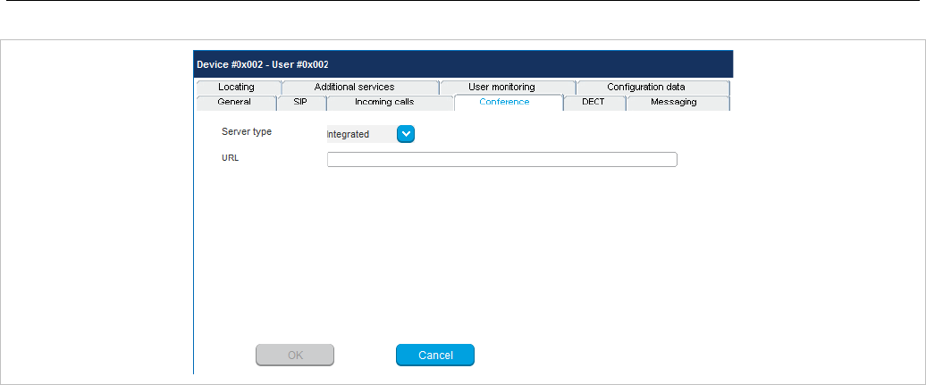
SIP-DECT OM System Manual
284
The default for the global system conference mode is None. For the user-specific mode, the default is
Global.
The global and/or user specific conference mode can also be configured via OMM configuration files or
the OMM application XML interface (AXI).
7.21.1 CENTRALIZED CONFERENCING
To enable SIP centralized conferencing on DECT phones select External as Server type for all users
on the OMP’s System -> SIP page or for specific users on the OMP’s DECT Phones -> Users page.
If there is specified a proxy / registrar server, then to reach the conference media server via the proxy
server, set the URI field to one of the following prefixes:
• conf (Sylantro server)
• Conference (Broadsoft server)
Examples
To set the URI field to “conf” or “Conference”, specify “conf@<proxy-server-address>:<proxy-port>” or
“Conference@<proxy-server-address>:<proxy-port>”.
To reach the conference media server using a different address/port then that is specified by the proxy,
set the URI field to “conf@<media-server-address>:<media-port>”
7.21.2 INTEGRATED CONFERENCE SERVER (ICS)
The conference server integrated in SIP-DECT is based on the SIP standard RFC 4579 and allows SIP-
DECT users the ad-hoc initiation of 3-way conferences.
If this feature is enabled, it allows SIP-DECT users having an active call and holding another call to
select 3 party in the Options menu of a Mitel 600 DECT phone to initiate an ad-hoc 3-way conference.
If a 3-way conference is initiated, the conference initiator and both connected parties are transferred to
the next free conference room hosted on one of the RFP 35 / 36 / 37 / 43 devices.
ICS provides the full range of voice codecs (G722, G711 µ-law, G711 a-law and G729) and supports
trans-coding for all parties in a three-way conference session.
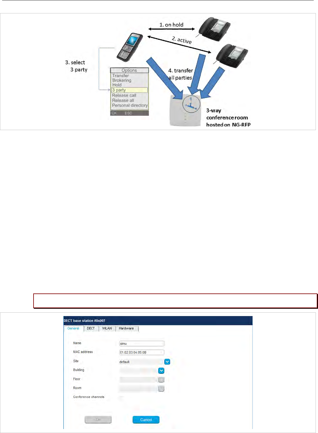
Configuration and Administration
285
Enabling the SIP-DECT integrated 3-way conferencing requires the following configuration steps:
• Enable internal conference mode
• Select RFP devices for conferencing
• Configure conference rooms
7.21.2.1 Enable internal conference mode
To enable SIP-DECT internal 3-way conferencing for DECT phones select Integrated as the Server
type setting for all users on the OMP’s System-> SIP page or for specific users on the OMP’s DECT
Phones -> Users page.
7.21.2.2 Select RFP devices for conferencing
Select some of the RFP devices from your SIP-DECT infrastructure to provide conferences. For this
enable the Conference cannels flag for each selected RFP on the OMP’s DECT base stations ->
Devices -> General tab (see section 6.7.1).
Please note: Only RFP 35 / 36 / 37 / 43 devices support 3-way conferences.
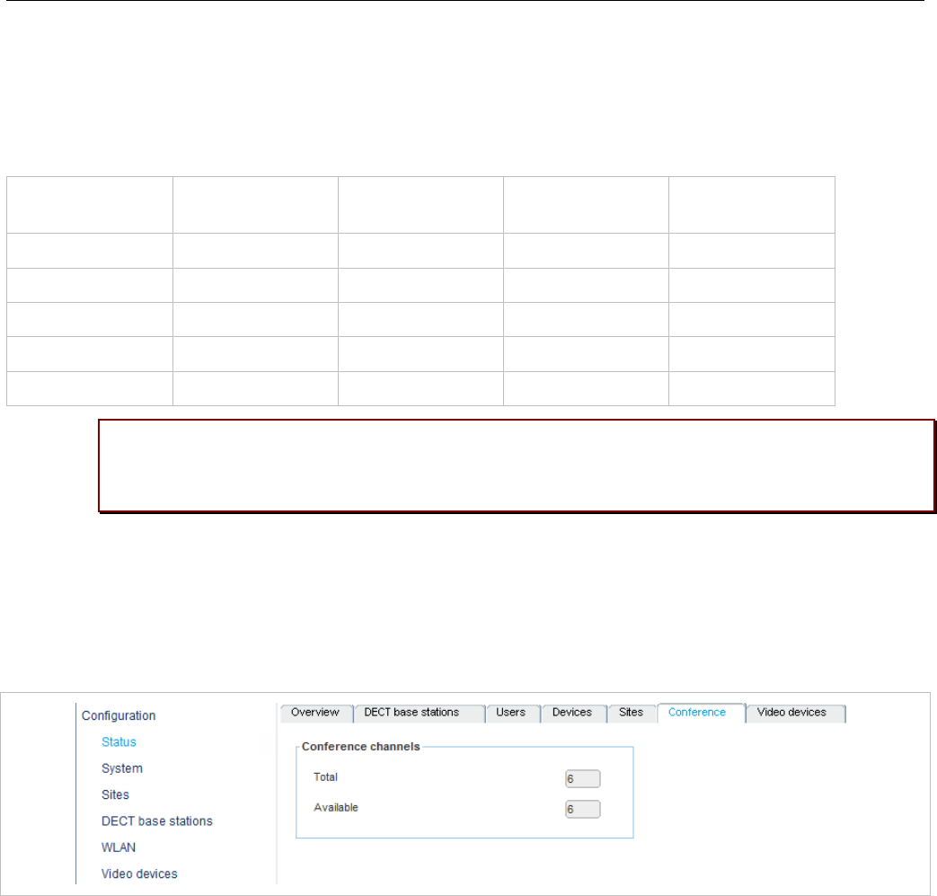
SIP-DECT OM System Manual
286
Depending on the DECT and G.729 configuration, an RFP device enabled for conferencing provides
between 3 and 24 conference channels. To compute one 3-way conference 3 conference channels are
necessary.
In particular, the G.729 codec, with its high consumption of computing time, reduces the number of
available conference channels according to the following table.
DECT enabled Conferencing
enabled
G.729 enabled Conference
channels
DECT voice
channels
Yes No Yes/No 0 8
Yes Yes No 15 8
Yes Yes Yes 3 5
No Yes No 24 0
No Yes Yes 9 0
Please note: Activating the Conference channels option on an RFP with enabled DECT
and in a system with enabled G.729 reduces the available DECT channels on that RFP
from 8 to 5.
If the G.729 codec is not necessary on your iPBX platform, disable the G.729 codecs on the OMP’s the
System: SIP page / RTP settings tab to obtain the maximum number of conference channels.
The total number of conference channels in the SIP-DECT system is presented the OMP’s Status ->
Conference tab. The Total parameter provides the total number of conference channels in the system
and the Available parameter provides the current number of available conference channels.
7.21.3 CONFIGURE CONFERENCE ROOMS
When a three-way conference is initiated by a SIP-DECT user, the initiator and the connected parties will
be transferred to the next free conference room using SIP signalling. These conference rooms must be
configured on the OMP’s Conference rooms page with their SIP user id and SIP password (see section
6.11).
Configure as many conference rooms as necessary and as conference channels are available (3
channels per conference).
These conference rooms will be SIP registered on the configured SIP registrar and must be reachable
via the configured SIP proxy for SIP signalling.
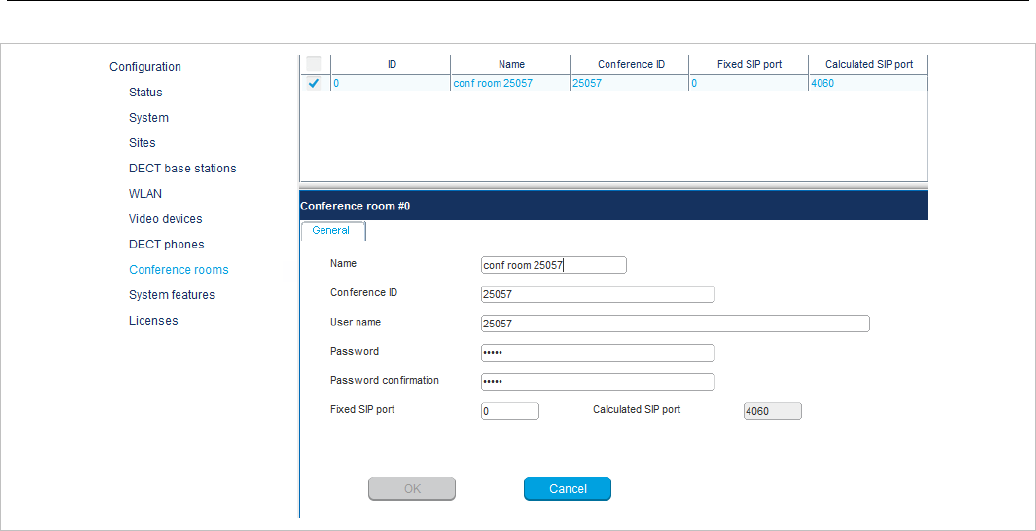
Configuration and Administration
287
The following parameters can be configured for each conference room
• Name: SIP display name
• Conference ID: SIP user id
• User Name: SIP authentication name
• Password: SIP password
• Fixed SIP port: port used explicitly for SIP signaling. If set to 0 (default), an automatically calculated
port is used for this conference room. See section 3.7 for more information.
• Calculated port: auto-calculated port used for SIP signaling (read-only). Only used if no value is
specified for Fixed SIP port.
All configured conference rooms will be registered on the registrar / iPBX configured in OMM. If the X-
Aastra-Id Info option is enabled on the OMP’s System: SIP -> Advanced settings tab, a private X-
Aastra-Id header is sent out which identifies that these are conference rooms.
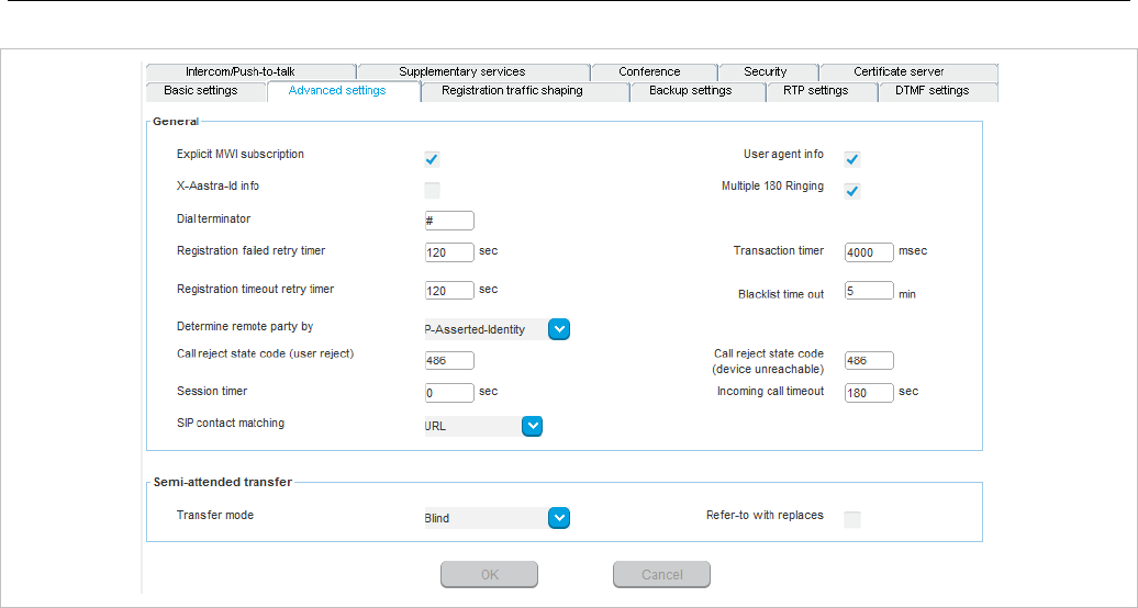
SIP-DECT OM System Manual
288
The X-Aastra-Id header has the following format for all conference rooms:
X-Aastra-Id: type="29" model="01" version="1.0.0"
The header’s attributes have the following properties:
type
• the type parameter contains the phone type
• the value for all SIP-DECT conference rooms is “29”
• type = DQUOTE (1*2HEXDIG) DQUOTE
model
• it’s the model of the terminal
• the value for all SIP-DECT conference rooms is “01”
• model = DQUOTE (1*2HEXDIG) DQUOTE
version
• the version is intended for later releases
• the value for all SIP-DECT conference rooms is “1.0.0”
• version = DQUOTE (1*16token) DQUOTE
7.22 DOWNLOAD OVER AIR
The “Download Over Air” feature allows updating the DECT phone firmware without any user interaction
or interruption of the telephony services over the existing DECT air interface. This feature is currently
available for the Mitel 600 DECT Phones.
With SIP-DECT 6.0 and later, the SIP-DECT RFP software image (iprfp3G.dnld) contains the Mitel 600
DECT phone software. If the RFP houses the OMM, the OMM uses this software to update the DECT
phones. The RFP OMM no longer automatically attempts to load a DECT phone software image from a
RFP software URL when provided via DHCP or local configuration.

Configuration and Administration
289
For specific maintenance purposes only, SIP-DECT allows configuration of a URL via the OMM Web
service or OMP to use an alternative DECT phone software image (see section 5.4.1.6). The Mitel 600
DECT phone firmware packages are delivered in the “600.dnld” file for the OMM running on an RFP.
7.22.1 HOW “DOWNLOAD OVER AIR” WORKS
If the “Download over Air” feature is activated (see section 5.4.1.6), the OMM acts as a download server
that provides the firmware for downloads.
The DECT phone sends its firmware version within the DECT attachment procedure. If the firmware
version does not match the version provided by the OMM, the DECT phone will be queued into the
update-queue. Later on the queued DECT phones will be paged to establish a download connection.
After the connection is established, the OMM sends its actual DECT phone firmware version and the
DECT phone will request a DECT phone description file. After receiving the DECT phone description file,
the DECT phone decides which files are missing or must be updated. If files are missing or must be
updated the DECT phone initiates the download procedure.
The OMM takes care of the following download scenarios automatically:
• If a DECT phones becomes unreachable e.g. when the DECT phone is switched off, the OMM will
update the DECT phone when the DECT phone becomes available again.
• The OMM will take care of the software download while the user is moving between base stations
(roaming) and location areas.
• The OMM has the capability of resuming a download from the point where it was last interrupted (e.g.,
the user leaves the coverage area during download or the DECT phone runs out of battery power).
• The OMM updates new DECT phones subscribed to the system.
• While the DECT phone is barred (e.g. low battery or “Download over Air“ is disabled at the local
menu), the download will be postponed.
The download happens without any user intervention. During the download, the telephony services, the
roaming- and handover procedures are still available. The download stops automatically when e. g. the
DECT phone leaves the coverage area or the RFP gets busy. The download resumes automatically
when the stop cause is solved.
The Mitel 600 DECT phones have two partitions in the internal flash memory to hold 2 different software
versions. During the download the new firmware is written to one partition and the DECT phone is
running from the other partition.
After the download is successfully completed, the new firmware will be activated when the DECT phone
is in the idle state.
The download of a single DECT phone with a firmware of 1 MB takes approximately 90 minutes. The
number of DECT phones which can be downloaded depends on the available system resources.
The number of simultaneous downloads is limited per OMM (RFP: 30, PC: unlimited) and per RFP (6,
decreased with each call).
The “Download over Air” service is delayed after a system startup for a while to allow the whole DECT
system to become active. This may last several minutes.
7.22.2 HOW TO CONFIGURE “DOWNLOAD OVER AIR”
This section describes configuration of the “Download Over Air” feature via the OM Web service. The
feature can also be configured using the OM Management Portal (OMP).
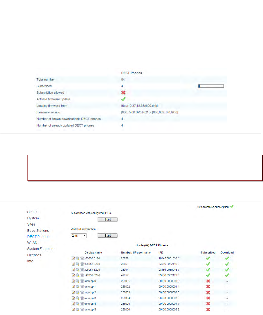
SIP-DECT OM System Manual
290
The “Download over Air” feature can be activated or deactivated on the System Settings web page (see
section 5.4.1.6).
In the OMP, you can enable the “Download over Air” feature in the System -> Advanced settings -> PP
firmware tab (see section 6.5.2.3).
If the “Download over Air feature” is activated, the status of the Activate firmware update parameter is
shown as enabled, service together with some statistics is displayed in the DECT phones section of the
Status web page.
The DECT phone firmware container for DECT phone firmware update over the air includes packages
for the Mitel 600 DECT phones. The available versions are also displayed on the Status web page.
Please note: The “Loading firmware from” on the OpenMobility Manager Status web page
is only updated on restart of the OpenMobility Manager. Changing the location while the
OpenMobility Manager is running has no effect.
The individual download status of each DECT phone is shown on the DECT Phones web page.

Configuration and Administration
291
The details in the Download column have the following meaning:
Icon Meaning
- Impossible to download the firmware to that DECT phone (e.g. not a Mitel 600 DECT
phone)
The DECT phone is paged to establish a download connection. In case of a successful
connection establishment the DECT phone calculates the number of bytes to download.
This may take several seconds.
xx kbytes left The download is ongoing and xx kbytes are left.
The firmware of this DECT phone is up to date.
The DECT phone is queued in the update-queue for updating (pending).
Warning
The download is barred because of one of the following reasons:
– The DECT phone is busy (temporary status).
– The battery power is lower than 50% and the DECT phone is not connected to the
docking station or the USB interface.
– This is not the master download system. A DECT phone can be enrolled on several
OpenMobility systems. The first system to which the DECT phone will be enrolled is the
“master system”. The DECT phone downloads only from the “master system”. A different
“master system” can be chosen inside the local menu of the DECT phone.
– The download is disabled in the local menu of the DECT phone.
The specific reason is shown as a tooltip.
Error
The download failed because of one of the following reasons:
– checksum error,
– file system error,
– error while writing firmware to flash,
– version mismatch,
– error while expanding firmware container.
The specific reason is shown as a tooltip.
Info
The download is not possible because:
– the DECT phone is not reachable
– the DECT phone is detached
The specific reason is shown as a tooltip.
In the OMP, the “Download over Air” service status is displayed in the Status menu (see section 6.4).

SIP-DECT OM System Manual
292
7.23 CENTRAL DECT PHONE CONFIGURATION OVER AIR (COA)
Centralized DECT phone configuration over the air is supported for Mitel 602 DECT phones.
Configurable parameters include:
• settings (loudness, contrast, etc)
• menu items (switch on or off, enable password protection)
• key assignments
• variable lists
DECT phone configuration over air (CoA) is useful for deployment of special configuration to a single
DECT phone or a large number of DECT phones. No local access to the DECT phone is required.
DECT phone CoA is implemented by providing additional configuration information to the well-known
configuration files or providing profiles via OMP. Configuration can be changed at the device level
(DECT subscription) or the user level (based on login).
Configuration of all DECT phones with a predefined default profile is also supported. Up to 20 DECT
phone profiles make it easy to adapt to different usage scenarios for heterogeneous user groups (e.g.,
nurses and doctors in hospital environments).
IMPORTANT : This feature requires 6.00 DECT phone software or later.
IMPORTANT : Centralized DECT phone conf iguration over the air is only available on
the Download over Air (DoA) master system.
7.23.1 CONFIGURATION FILES
You can use three kinds of configuration files:
• Default DECT phone configuration profile
Default configuration file used for all suitable DECT phones. The configuration is loaded into the
DECT phone when subscription is complete, even if a user has not logged in to the device.
• DECT phone configuration profiles
User-focused DECT phone configuration file used for a group of users. The configuration is loaded
into the DECT phone when a user belonging to this group logs in to the device.
• DECT phone user individual configuration settings
Individual DECT phone configuration settings used for a single user. The configuration is loaded into
the DECT phone when the user logs in to the device.
The system consolidates the DECT phone settings before loading the configuration settings for a logged-
in user into the DECT phone. Settings from DECT phone profiles overwrite default configuration settings,
and individual user configuration settings overwrite DECT phone profiles and default configuration
settings. For a complete list of supported settings, see section 9.7.
Configuration can be completed by using OMP (file import and download configuration settings) and user
configuration files (user_common.cfg and <user.cfg files), wherein a list of user friendly settings can be
used for the DECT phone configuration.

Configuration and Administration
293
Please note: Deleting or overwriting configuration files on a DECT phone does not restore
configuration to default or previous settings. Configuration elements that are not part of
the new downloaded configuration file persist. To restore all settings, the administrator
must initiate a power off/on at the DECT phone or use a default configuration file that
contains all relevant settings.
To avoid interfering with the telephony or message service (especially with respect to alarm messages
within the SIP-DECT system), only one configuration data download to the DECT phone is performed at
a time. Therefore, changing the default profile settings or other profile settings may take some time in a
large system, until all the related DECT phones are updated.
7.23.2 CONFIGURATION FILE DOWNLOAD TO DECT PHONES
Profiles are downloaded to the DECT phone via the messaging mechanism, in conjunction with the
internal message type “CONF_OVER_AIR”. This occurs in parallel with general message transfer to the
DECT phone, and the lowest priority is used to ensure that the download does not interfere with the
delivery of urgent messages. The message mechanism is also used to confirm a successful profile
download, through AXI events.
Profile downloads to DECT phones are limited system-wide to a maximum of one download at a time to
ensure no interference with OMM system operation. You can view the download on the OMM console
(console command hcm).The download state is also part of the system dump.
7.23.2.1 Download Triggers
The OMM maintains a profile download list for all DECT phones that have configuration data to be set.
These DECT phones are stored with the checksum of configuration data to be set. A DECT phone is
included in this list when:
• the OMM system starts up and the associated DECT phone has configuration data to be set
• the associated DECT phone’s configuration data changes (this is communicated via AXI), such as:
- change in the default configuration profile
- change in the configuration profile for the user of the associated DECT phone
- change in the individual user configuration profile for the user using the associated DECT phone
- change in the configuration profile assigned to the user using the associated DECT phone
Profile downloads to the DECT phones (as maintained in the profile download list) are scheduled at
regular intervals. A new download to DECT phones in the profile download list is scheduled when:
• a configuration change occurs on the DECT phone (via AXI notification)
• a location registration is received, and the checksum of the configuration data stored in the profile
download list is different from the checksum sent in the location registration
• a download to a DECT phone completes
7.23.3 COA CONFIGURATION USING OMP
OMP configuration of DECT phones is restricted. You can do the following through OMP:
• list the current user and device state via the DECT Phones -> Overview menu and DECT Phones ->
Devices -> Configuration data tab (in Monitoring mode)

SIP-DECT OM System Manual
294
• import the default profile and one to 20 individual profiles via the System features -> COA profiles
menu (see section 6.12.7)
• assign one of 20 profiles to an internal user via the DECT Phones -> Users -> Configuration data
tab (see section 6.10.4.10)
The syntax of the profiles that can be imported by the OMP is the same as that specified for the
user_common.cfg and <user>.cfg files.
Please note: CoA configuration via OMM Web service is not supported. You can only list
the current user and DECT phone state in the “User and DECT phone configuration and
status data summary”.
7.23.4 CONFIGURATION USING USR_COMMON.CFG/<USER>/CFG FILES
The user_common.cfg and <user>.cfg configuration files are used for DECT phone configuration. The
following configuration attributes in the user_common.cfg file control central DECT phone configuration:
• Default profile settings
OM_Profile.0.Default.<key>=<values>
…
OM_Profile.0.Default.<key>=<values>
Where “Default” is the reserved name for the default profile, and <key> is one of the configuration
settings with its <values> to be set.
Example:
OM_Profile.0.Default.UD_DispLang="en"
OM_Profile.0.Default.UD_DispFont="large"
OM_Profile.0.Default.UD_DispColor="black"
• one of up to 20 profile settings
OM_Profile.<no>.<name.<key>=<values>
…
OM_Profile.<no>.<name>.<key>=<values>
Where <no> is the number of the profile, <name> is the name of the profile to be configured, and
<key> is one of the configuration settings with its <values> to be set.
Example:
OM_Profile.5.Doctor.UD_DispLang="en"
OM_Profile.5. Doctor.UD_DispFont="large"
OM_Profile.5. Doctor .UD_DispColor="black"
Please note: To assign a profile to a user, you can use the UD_PpProfileId= <profileNo>
setting in <user>.cfg files. When <profileNo> is 0, no profile or (depending on
configuration) the default profile is used. The default profile is defined in
user_common.cfg.

Configuration and Administration
295
Please note: A complete removal of a profile from user_common.cfg does not remove the
profile in the OMM database. It must be explicitly deleted in the OMM database.
For individual user DECT phone configuration settings, the following configuration attributes are
available in the <user>.cfg file:
• User configuration settings
<key>=<values>
…
<key>=<values>
Where <key> is one of the configuration settings with its <values> to be set.
Example:
UD_DispLang=”en”
UD_DispFont=”large”
UD_DispColor=”black”
7.23.4.1 CoA Example
UD_ConfigurationName = "omm-test"
UD_DispLang="en"
UD_DispFont="small"
UD_DispColor="black"
UD_RingerMelodyIntern="ringing_1"
UD_RingerMelodyExtern="ringing_2"
UD_RingerVolumeIntern="increasing"
UD_RingerVolumeExtern="increasing"
Configuration file is named “omm-test”
Language is set to English
Display font is set to small
Display color scheme is set to black
Internal call melody is set to melody “ringing_1”
Internal call melody is set to melody “ringing_2”
Internal call ringer volume is set to increasing
External call ringer volume is set to increasing
See section 9.7 for a full list of supported CoA configuration parameters.
7.23.5 VARIABLE LISTS
The Mitel 602 DECT phone 6.1 firmware introduces the variable lists. A variable list includes a number of
items, each of which correspond to an action to be performed on the DECT phone.
A list item consists of an index identifier (1..10) and either a number (to be dialed) or a function/feature
that is supported by the DECT phone. Other attributes are optional. If there is a FunctionID, the entry
does not have a sub key line in the variable list. If there is a number and a FunctionID the DECT phone
executes the associated function (if available); otherwise, the DECT phone dials the Number.
Item Attribute Type Description Example
Index Decimal number Index of list item (1..10) 7
Number quoted UTF8-string Number to dial “\x2312*777*”
(use \x23 for # in configuration file)
Name quoted UTF8-string Text displayed for item “My Voice Box”
FunctionID Function-ID-string Function or feature to execute pbx_directory
ShortName/Icon quoted UTF8-string Short name and/or icon
displayed “\xEE808B VB”

SIP-DECT OM System Manual
296
Handsfree Boolean (“” or 1) Dial in hands-free mode 1
VisibleSpecifier 4 digit string of “0” or “1” Item visible in idle, dial, alerting
and active state 1000
The CoA profile supports two variable lists for each DECT phone. Each list can contain up to 10 items.
Use the UD_VListEntry configuration command to configure an item for one of the lists. The first
value specifies the index (1 or 2) of the list, followed by the attributes listed above.
Note that the values-attribute pairs must be separated by a space and their position in the configuration
command are fixed. Unused attributes must be indicated by empty strings if they are followed by
nonempty attributes. Unused attributes (empty strings) can be omitted at the end of the configuration
command.
A variable list can hold a name and/or short name (used to represent it in another list or near a
programmed soft key or side key). The ‘short name’ attribute also allows you to specific an icon. A third
attribute, ‘sub item’, determines whether or not are subitems (sub key lines) of a list are displayed. By
default, the subitem (sub key line) is only displayed if the item is selected.
List Attribute Type Description Example
Name quoted UTF8-string Text displayed for list “My Own Menu”
ShortName/Icon quoted UTF8-string Short name and/or icon
displayed “\xEE808B M1”
SubItems Boolean (0 or 1) Show sub-key line of
selected item 1
Examples:
#PBX Menu using COA variable list
UD_ConfigurationName=PBX Menu
#Key assignment (function: vlst1 and vlst2)
UD_KeyAssignmentIdle=esc vlst1
#Menu Design
UD_VListName = 1 "Call services" #Titel
UD_VListShortName = 1 "More" #Softkey
UD_VListSubItems = 1 0 #Display Details per Item
### PLACEHOLDERs to add into Number field:
#<no> will be replaced with a number from handset editor e.g. "*12*<no>#"
#<dial> will be replaced with a number from handset editor or directory, caller-list...
#<t=…> following dial-digits will be delayed for ... ms e.g. <t=3000ms>
#<inf=...> set info-box with ... string for (3000ms) continue dialing after info box e.g.
#<inf=Please wait>
#<r=...> call will be released after ... ms e.g. <r=10000>
#<close> will close this Menu.

Configuration and Administration
297
### Entry: UD_VListEntry = List Index "Number" "Name" FunctionID "ShortName" Handsfree
# Visible
#ITEM TYPE DESCRIPTION
#List decimal number item belong to variable list (1..2)
#Index decimal number index of list item (1..10)
#Number quoted UTF8-string number to dial "*1234" (use \x23 for #)
#Name quoted UTF8-string displayed text of item "My Voice Box"
#FunctionID function-ID-string function/feature to execute e.g. pbx_directory
# (if available, preference over number)
#ShortName quoted UTF8-string displayed short name and/or icon
#Handsfree Boolean (0 or 1) dial in hands-free-mode
#Visible 4-digit-string of 0 or 1 item visible in idle-, dial-, alerting- and
# active-state e.g.1000
#notice: to skip a parameter in the row use "" (even if the type is unquoted)
### idle menu functions
#Call Forward **8 (predial) + number
#Call Forward Cancel ##8 (dial)
#Do Not Disturb *5 (dial)
#Do Not Dist. Cancel #5 (dial)
#Call Pickup *6 (dial)
#Call Park Retrieve *8# (predial) + number
#Direct/Group Page *37 (predial) + number
#Loudspeaker Page **9 (dial)
UD_VListEntry = 1 1 "**8<dial>\x23<inf=Call FWD enabled><r=2000>" "Call Forward" "" "" ""
UD_VListEntry = 1 2 "\x23\x238<inf=CallFWD off><r=1000><close>" "Call Forward Cancel" ""
"" ""
UD_VListEntry = 1 3 "*5<inf=DND enabled><r=1000><close>" "Do Not Disturb" "" ""
UD_VListEntry = 1 4 "\x235<inf=DND off><r=1000><close>" "Do Not Dist. Cancel" "" ""
UD_VListEntry = 1 5 "*6<close>" "Call Pickup" "" "" ""
UD_VListEntry = 1 6 "*8\x23<dial>" "Call Park Retrieve" "" "" ""
UD_VListEntry = 1 7 "*37<dial>" "Direct/Group Page" "" "" ""
UD_VListEntry = 1 8 "**9<close>" "Loudspeaker Page" "" "" ""
7.23.5.1 Icon coding
The following table lists the UTF8-codes for Mitel 602 DECT phone icons.
ICON UTF8-Code Description
\xEE8083 Arrow Up
\xEE8084 Arrow Down
\xEE8085 Arrow Left
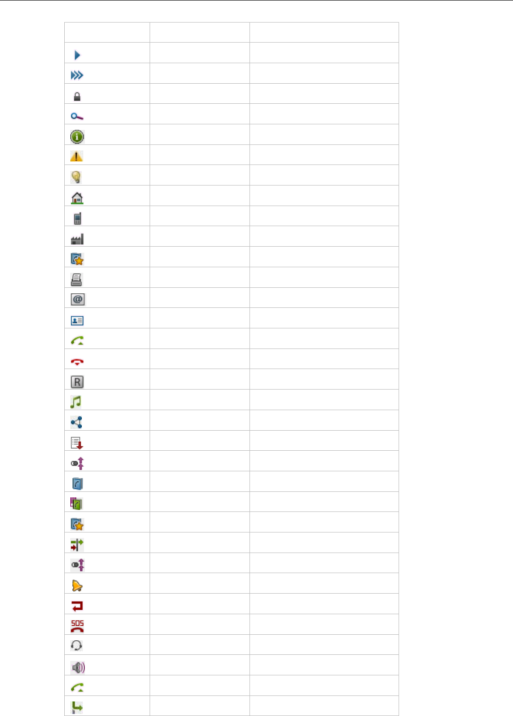
SIP-DECT OM System Manual
298
ICON UTF8-Code Description
\xEE8086
Arrow Right
\xEE8088 Fox Key
\xEE80B0 Locked
\xEE80BC
Search
\xEE80BE Info
\xEE81A5 Attention
\xEE80BA Tip
\xEE808A Telbook Private number
\xEE808B Telbook Mobile number
\xEE808C
Telbook Business number
\xEE818C VIP number
\xEE808D Telbook Fax number
\xEE808E Telbook Email address
\xEE808F Telbook Name
\xEE809B Hook off / Predial
\xEE809C Hook on / Release
\xEE81B0 Register recall
\xEE8092 DTMF
\xEE8182 3-party
\xEE80A0 List Incoming call list
\xEE80A1
List Outgoing call list
\xEE8196 List Private directory /
\xEE8199 List Central directory
\xEE818C List VIP
\xEE8181 List Filter / Call Filtered
\xEE80A1 Call outgoing
\xEE8099
Call Waiting
\xEE80A7 Call Rejected
\xEE81AD Call SOS
\xEE809D Call Headset autoanswer
\xEE8098 Call Loudspeaker autoanswer
\xEE809B Call Hook autoanswer
\xEE80B8 Call deflected

Configuration and Administration
299
ICON UTF8-Code Description
\xEE80A3 Call missed
\xEE80A4 Call answered
\xEE8195 Call on Voicebox
\xEE81AE Call VIP
\xEE81B1 Pickup
\xEE81B2 Pickup select
\xEE8296 Call Park
\xEE80BF
Call protection
\xEE8298 Call routing
\xEE8292 Callback
7.23.5.2 Number string coding
Note that the number specified in the list item may include one or more placeholders, so that, for
example, the user can enter a number before the number is dialed. The placeholder keywords are
specified in angle brackets ("< >").
If the dialed number includes angle brackets, you must use “<< >>”.
Number Placeholder Description
<no> If the number strings consists of <no>, it is replaced with a number from the DECT
phone editor
<dial> If the number string consists of <dial> it is replaced with a number from the DECT
phone editor or directory, caller-list. For example, "*12*<no>#" -> ok <edit-number>
send cc-info"*12*"<edit-number>"# (numbers may include letters like abcd... if the
system supports alpha dialing)
<close> All parents (e.g a list from witch this item is started) are closed
<t=…> Following dial-digits are delayed for ... ms e.g. <t=3000ms>
<inf=...> Set info-box with ... string for (3000ms) continue dialing after info box ( e.g.
<inf=Please wait>)
<r=...> Call is released after ... ms e.g. <r=10000>

SIP-DECT OM System Manual
300
7.24 EXTENDED DECT PHONE INTERFACE
With SIP-DECT 6.0 and later, the Mitel 600 DECT phones include an Administration menu that offers
administrative functions to the user such as login, logout, and configuration and status summary display.
The menu is available as an option under the System menu which can be accessed via the main menu
of the DECT phone, or directly by a long press of the right soft key “>>>”.
Please note: The Administration menu is only available on Mitel 600 DECT phones,
version 4.0 or higher.
The following table summarizes the options under the Administration menu. The menus allow basic
OMM configuration and require a login (the same account and password as used for administrative
access via OMP or Web service).
Menu option Description OMM login
1. Login User can log in to the DECT phone (free DECT phone only)
2. Logout User can log out of the DECT phone (free DECT phone only)
3. PP state Display user/device configuratoin and status data summary
(see section 5.7.6 for details)
4. Sync user data Refresh SIP registration and synchronize user data, if they are
stored externally
5. Sync system data Reload configuration and resource files Yes
6. System credentials Set authentication for provisioning servers (see section
7.8.6.1) Conditional
7. Status Display basic OMM network settings (e.g., DHCP, IP
addresses)
8. System Set basic OMM system data Yes
9. SIP users/devices Perform basic configuration of users and DECT phones Yes
10. Version Display current OMM software version
The options available depend on the DECT phone state and the OMM platform (i.e., RFP OMM or Linux
Server). The following table summarizes the options under the Administration menu according to
device state and OMM platform.
Menu option Fixed device Logged out Logged in RFP OMM Linux Server
OMM
1. Login √ √ √
2. Logout √ √ √
3. PP state √ √ √ √
4. Sync user data √ √ √ √

Configuration and Administration
301
5. Sync system data √ √ √ √ √
6. System credentials √ √ √ √ √
7. Status √ √ √ √
8. System √ √ √ √ √
9. SIP users/devices √ √ √ √ √
10. Version √ √ √ √ √
The following table summarizes the submenus available according to the OMM platform.
Submenu SIP-DECT RFP OMM Linux Server
OMM
1. System name √ √ √
2. Date and Time √ √
3. SIP √ √ √
4. User administration √ √ √
5. Restart √ √ √
7.25 OMM/DECT PHONE LOCK WITH BRANDING ID
With SIP-DECT 6.0 and later, customers can use a specific branding key to lock the OMM. The key must
be branded to all DECT phones before they can be subscribed.
Note: This feature is only available by special request. Please contact
your Mitel representative for more information.
You generate the branding key using the DECTSuiteBrandingInstallation.exe tool (provided by
Mitel on special request). When you have the generated keys, you set the branding key in the OMP, via
the System -> Advanced Settings -> Special branding tab (see section 6.5.2.7).
The branding key can be only removed from the OMM system by using a special key, also generated
with the DECT-Suite PC Tool and entered in the OMP Special branding tab. You must remove the
branding key before changing to a different brand.
7.25.1 SUBSCRIBING THE DECT PHONE
The user who subscribes the DECT phone must explicitly invoke the transfer of the branding key (done
in the AC-Editor).
Add “R*” (or “R<additional_id>” in one case) as a suffix to the typed AC code (or just R*, if there is no AC
code).
• Type R* for normal subscription for fixed devices.

SIP-DECT OM System Manual
302
• Type R* for auto-create by subscription.
• Type R* for wildcard subscription without DECT phone data record selection.
• Type R<additional_id> for wildcard subscription with record selection by the additional id.
7.26 DEVICE PLACEMENT
The OM Locating application uses small graphic maps for visualization of DECT base station placement.
From SIP-DECT release 3.1 on, these graphics can be created with the OMP in Planning Mode.
7.26.1 “PLACEMENT” VIEW
By using the mouse with drag and drop, you can move RFP icons to their correct mounting position on
the loaded background image. Note that you must provide background images first (see also /27/).
A DECT base station is drawn as green circle with its ID number inside.
Background images can be loaded into the application on the Image Management panel (see section
7.26.3).
The assignment of devices to the currently active image must be done on the DECT base stations
page.
7.26.1.1 Functionality of the “Placement” View
• Left mouse click selects/deselects the DECT base station the mouse is pointing to. A selected device
is shown with thicker border.
• Drag and drop functionality: a device can be moved while the left mouse button is pressed and hold.
• If left mouse button is hold and no device is selected, the complete view content gets moved.
• By turning the mouse wheel the view gets scaled up or down depending from the direction of turning.
• By pressing the right mouse button a pop-up menu is displayed:
- Move selected RFPs: All selected devices (drawn with a thick border) will be moved to the current
position of the mouse pointer. Distances between the devices are not changed as long as all
devices can be drawn inside the background image. Moving devices to the area outside the upper
or left border of the image is not possible.
- Reset selection: The selection is canceled for all currently selected devices.
- Remove selected device(s): Selected devices are removed from the current image after
confirmation in a dialog box. Those devices can be assigned to an image again via the DECT base
stations menu (see also section 7.26.2).
If no devices are selected but the mouse is pointing to a device, that device is removed from the
image without further inquiry.
- Reset view: The view is redrawn in its original appearance. Any translation and scaling applied to
the view is cancelled.
7.26.1.2 Activation of the “Placement View”
The Placement view can be activated by:
• Selecting the Placement view menu entry. The currently loaded image with its assigned devices is
displayed. If no image is currently loaded, the view is empty.

Configuration and Administration
303
• Double-clicking on a table row in the DECT base stations view. This activates the placement view
with the image the clicked device is assigned to.
• Selecting the Assign to active image task in the DECT base stations view. The selected devices
are assigned from the table to the current image.
If a selected device was already assigned to another image, the assignment is changed upon
confirmation in a dialog window.
• Selecting an entry in the Image management view (double-click or click on Show image task).
7.26.2 “DECT BASE STATIONS” VIEW
The view shows a table based list of RFP.
When you select table rows and click Assign to active image, the selected devices are assigned to the
currently active image. Devices already assigned are tagged with a green sign in the table column
Positioned.
If a selected device was already assigned to another image, the assignment will be changed when
confirmed through a confirmation dialog.
7.26.3 “IMAGE MANAGEMENT” VIEW
With the Image management view all background images assigned to the SIP-DECT system can be
managed. Also, the generation of the graphic maps used by the OM Locating application can be started
by this view.
If the user activates this view and a background image was loaded, the OMP automatically creates a
project file the current SIP-DECT system on the PC. This file contains references to the background
image files and the device assignment and placement coordinates. It automatically gets reloaded to the
application if the OMP user enters the Device Placement menu again during a connection to the same
SIP-DECT system.
The images and placement coordinates are stored only on the local PC and not together with the SIP-
DECT system configuration (due to storage size limitations). Therefore it is recommended to export the
project and save the project data at a secure place after finishing the placement of devices for a SIP-
DECT system.
7.26.3.1 “Show image” Task
After selecting an image entry from the table with a left mouse click and then selecting the Show image
task, the image will be displayed with its assigned devices in the Placement view.
A left mouse double click on a table entry also opens the Placement view.
7.26.3.2 “Add image” Task
With the Add image task, the user calls up a File Open dialog which allows the addition of one or more
background images stored on the PC to the system.
The OMP supports *.jpg and *.png image files. A maximum of 800 images can be managed by the OMP.
The maximum size per image is limited to 3000 pixel in both height and width.

SIP-DECT OM System Manual
304
7.26.3.3 “Remove image” Task
The selected image table entries will be removed from the current project after an inquiry dialog. All
devices which were already assigned to one of the removed images will be reset to unassigned state.
7.26.3.4 “Generate” Task
By choosing this task the user can start the generation of the graphics data needed by the OM Locating
application. The OMP will only create graphics data for selected image table.
In a file save dialog the user can select a storage directory for the generated graphics data. A progress
dialog informs about the actual status of the generation process. If the process is canceled by the user,
the OMP will finish generation of graphics data for the actual background image before stopping the
process.
7.26.3.5 “Import project” Task
With the Import project task the user can load a previously exported project. Images and device
placements done before importing a project will be substituted by the data contained in the project.
The system name and the PARK are not checked during this operation. It is possible to import a project
created for another system or after the system name or PARK was changed.
Devices are managed by their IDs. If a device ID from imported data cannot be matched with a device ID
from the system the OMP is currently connected to, the placement data for such a device will not be
imported.
The image files will not be copied. The actual project will save references to the storage place of the
images.
7.26.3.6 “Export project” Task
With the Export project task, the user opens a File Save dialog where the user can select a directory for
the exported data, or create a new one.
The OMP exports the project file and copies all background image files to the chosen destination.
A project exported with this task can be imported again via the Import project task.
7.26.3.7 “Adjust overview size” Task
The OM Locating application needs two graphic maps for each device:
• One detail map image showing the position of an RFP in same scale as the background image on
which the device was placed.
• An overview map showing a bigger area of the background image down scaled and the position of the
RFP.
There is no special requirement to the scale of the used background images. The selection of the
overview scale may differ depending from building or area proportions.
With the Adjust overview zoom task the user can adjust the down scale zoom factor for the overview
map images (2) individually for the currently selected background image.
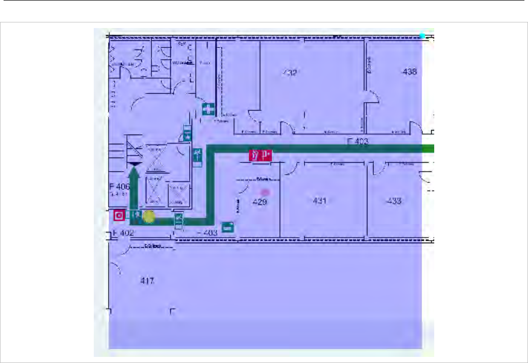
Configuration and Administration
305
The content of an area generated as overview map is shown by the transparent overlay square.
Changing the size of this area can be done by grabbing the light blue point at the right upper edge and
moving the edge to (or away from) the center of the area.
By grabbing the red point in the middle of the overlay square it is possible to move the overlay square
around.
For generation of the overview map images the position of overlay square does not matter. Only the size
is important to calculate the scale ratio for down scaling.
7.26.3.8 “Set overview size” Task
Instead of adjusting the scale factor for down scaling on generation of overview maps with the method
described in section 7.26.3.7 it is possible to set a scale factor for the selected images.
The value of the scale factor must be chosen with the slider Overview size in the task panel prior to
assign it to one, several or all images with the Set overview size task.
7.27 MONITORING WITH USB VIDEO DEVICES
To use an USB video device in interaction with the OM Locating application, a video user account must
to be configured. In addition the configuration and activation of a video device (“USB Web Cam”) itself is
needed.
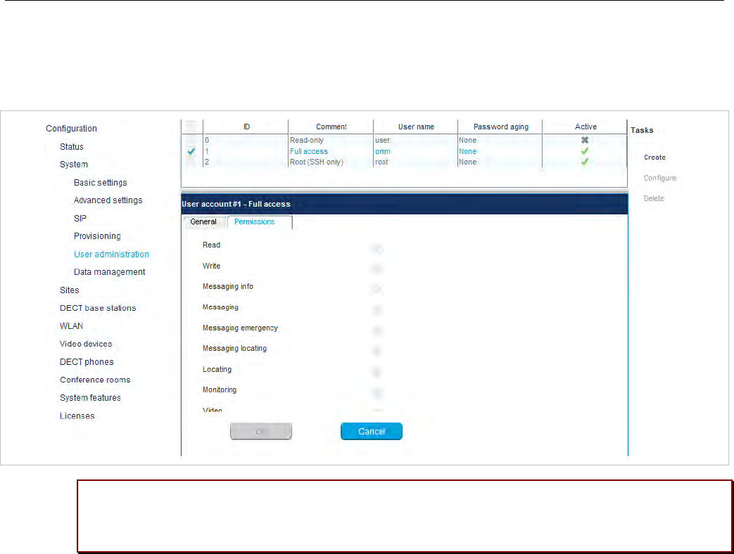
SIP-DECT OM System Manual
306
7.27.1 CONFIGURATION OF A VIDEO USER ACCOUNT
An active user account with at least read and video permissions must to be configured, to use it inside
the OM Locating application.
Please note: If you have already configured the OMM’s “Full access” account within the OM
Locating application to access OMM service, you must change this account to the video-
enabled account created in this step.
7.27.2 CONFIGURATION OF USB VIDEO DEVICES
You configure video devices on the OMP’s Video devices page (see section 6.9). The Video devices
page contains a list of known video devices and you can access the configuration window for the video
devices by double-clicking on an entry. Use the left side of the panel to enter a description of the camera
and its position. On the right side of the window, you can set the parameters for Resolution, Frame rate
and Rotation.
Keep in mind that the chosen parameters for resolution and frame rate must fit the parameter
specifications of the camera device and that changes on this parameters are not possible on cameras
which have the state “started” (i.e. viewed in the OM Location application).
If a camera is installed in a way that the images which are sent by the camera are rotated (e.g. upside
down), use the parameter Rotation to have the right view on the images inside the OM Locating
application. By setting the Active option the video device is permitted to send images.
7.27.3 MONITORING WITH USB VIDEO DEVICES
Using the OMP monitoring mode for a video device opens a window with two tabs, the General tab and
the Status tab. On the General tab the actual configuration of the video device will be shown. On the
Status tab the actual status of the camera device will be shown. The tag is an internal identifier of a
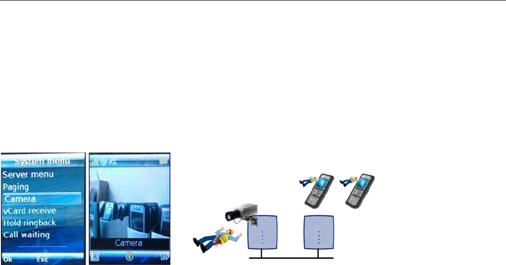
Configuration and Administration
307
video device, the RFP ID is the identifier of the RFP the video device is plugged in, USB path is an
identification of the plug-in position and State is the actual state of the video device.
7.28 TERMINAL VIDEO
As of SIP-DECT 5.0, Mitel 600 DECT phones support video streams from cameras connected to SIP-
DECT RFP 35/43 base stations. When a user has video stream permission, he can choose in the
system menu from a list of cameras to connect.
Video Streaming is only available when the DECT phone is connected to a RFP 35/36/37/43 and the
permission is set for the site and the DECT phone.
Video streams are treated like a call by the DECT phone, which require two (of eight) air channels on the
RFP for each stream. The DECT phone can also perform handover between RFPs with an active video
connection.
A video connection is automatically terminated by the system in case that any related capability (e.g.
video stream permission) is changed.
7.28.1 TECHNICAL DETAILS
Terminal video resolution and framerate are independent from the configured camera resolution and
framerate.
The resolution of the terminal video stream is automatically downscaled to 176 * 144 pixels (QCIF) with a
frame rate of approximately 2 frames per second.
The resulting overall delay is below 2 seconds.
The maximum number of simultaneous terminal video streams per camera is restricted to 10.
7.28.2 OMP CONFIGURATION STEPS
Connection and configuration of cameras is similar to the already known steps referring to the locating
application. Special steps necessary for terminal video are:
• Enable all sites, which have the technical capability (only RFP 35/36/37/43 are referred to it), via
OMP for terminal video.
• Enable via OMP (DECT Phones -> Users -> Additional services) by setting the “Video stream
permission” for those users who are allowed to use this feature.

SIP-DECT OM System Manual
308
Please note: It is strongly recommended to set the DECT base station attributes “building”,
“floor” and “room”, if you configure a huge system with a large number of cameras. This
will ease the selection of cameras on the DECT phone menu.
7.28.3 CAMERA SELECTION VIA HANDSET MENU
The selection of the menu “Cameras” is offered in the Mitel 600 DECT phone “System menu” (e.g. long
press on Menu >>>), if
• at least one camera is plugged and activated by the enable flag
• the DECT phone user has the permission to select cameras
• the DECT phone is located within a site, which allows terminal video
Navigation within the camera menu will be done by OK (and ESC) keys. To establish a video stream,
press “hook off” if the name of your camera is selected.
If the number of cameras exceeds the visible lines of the DECT phones display, the presentation is
arranged hierarchically. At least one sublevel must be selected in this case before camera names are
offered. The hierarchy of the referred radio fixed parts (site, building, …) is inherited for that purposes.
The destination of a video call is added to the DECT phone internal redial list.
Please note: During an established video link, audio calls or any system service activities
are not possible.
Any kind of auto callback (initiated by a message by a message or pushed by xml notification to direct
dial) is not supported.
7.29 USER MONITORING
To check the availability of a user in terms of the possibility to receive calls or messages, the OMM
monitors the status of the user’s DECT device.
7.29.1 OVERVIEW
With the “user monitoring” feature the following fixed set of status information is monitored:
Is a DECT phone assigned to the user? Handset assignment status (HAS)
Is the DECT phone subscribed to the DECT system? Handset subscription status (HSS)
Is the DECT phone currently registered /signed in? Handset registration status (HRS)
Are there DECT phone activities within a specific
timeframe? Handset activity status (HCS)
Is the user registered at the SIP registrar? SIP user registration status (SRS)
Is the DECT phone not in silent charging mode (silent
charging option active and in the charger cradle)? Silent charging status (SCS)
Is the feature “immediate call diversion” inactive? Call diversion status (CDS)
Is the battery charge higher than the configured
threshold? Handset battery state (HBS)
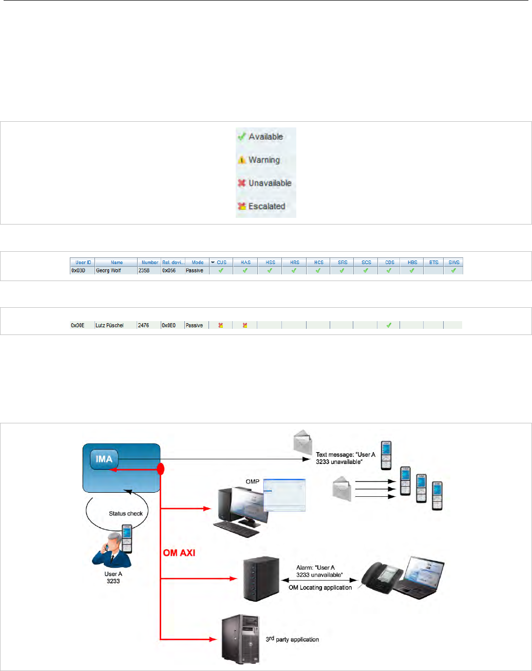
Configuration and Administration
309
Does the DECT phone have the minimum required
software version? Software Status (SWS)
If all questions can be answered with “Yes” then the user status is set to “Available”. This set of status
information is monitored if user monitoring is enabled for a user.
The status of all monitored users is displayed in the DECT Phones -> User monitoring menu (see also
section 7.29.7.3). The status information can have one of the following values:
The sum of all specific states is presented by the “Combined User Status”.
If one of the states is set to unavailable, the resulting Combined User Status is set to unavailable as well.
Because of dependencies between the states, some states cannot be determined if a higher level state
is not fulfilled. For example, if the user has no DECT phone assigned, the DECT phone registration
status cannot be determined. If a status cannot be determined, the status value is set to “Unknown”
(empty in OMP).
The status information is available via OM AXI and OMP.
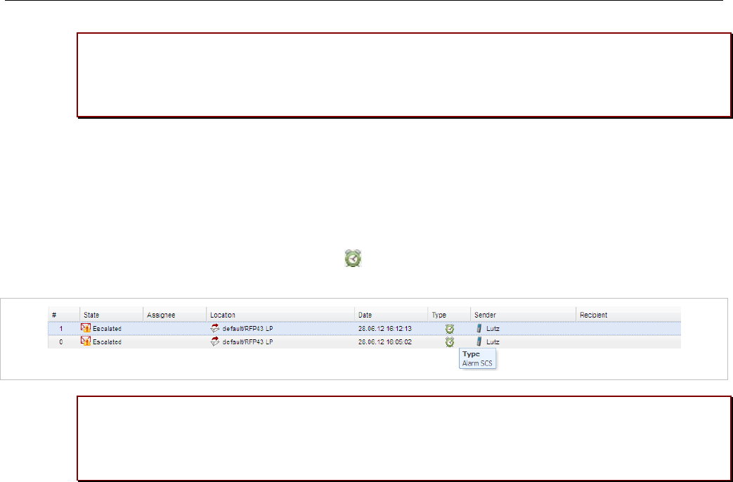
SIP-DECT OM System Manual
310
IMPORTANT : To address customer specific requirements, external applications (e.g.
3rd party software) can provide an addapted functionality of the user monitoring or
even more just by using OM AXI. This can be completed by the use of the XML
terminal interface.
In addition to the standard request, response and notification messages, the OMM generates alarm
triggers if a user becomes unavailable. The alarm triggers can be consumed by the OM IMA, OM
Locating or another application using OM AXI. If a user becomes available again, the OMM informs
about this status change by sending an additional alarm trigger.
The specific alarm trigger “LOC-ERR-USERSTATE” is defined for locating. This alarm trigger is
displayed in the OM Locating application with the icon.
IMPORTANT : The OM Locating application does not list users who are not locatable,
e.g. locating not enabled for the users or because they have no DECT phone
assigned. Therefore, the OM Locating application can no t handle the LOC-ERR-
USERSTATE with the escalation of the DECT phones assignment state (HAS).
7.29.2 STATUS ATTRIBUTES AND VALIDATION MECHANISMS
The combined user status (CUS) is the sum of the specific status information.
The CUS is calculated based on the flowing rules:
• Specific states which are set to “Unknown” are ignored.
• CUS is set to “Available” if none of the specific states is set to “Warning”, “Unavailable” or “Escalated”.
• CUS is set to “Warning” if at least one of the specific states is set to “Warning” and none of the other
states is set to “Unavailable” or “Escalated”.
• CUS is set to “Unavailable” if at least one of the specific states is set to “Unavailable” and none of the
other states is set to “Escalated”.
• CUS is set to “Escalated” if at least one of the specific states is set to “Escalated”.
The status “Unavailable” is changed to “Escalated” after the escalation timeout has elapsed and an
alarm trigger has been generated.
7.29.2.1 Handset Assignment Status (HAS)
A DECT phone must be assigned to the user otherwise the status is “Unavailable”.
Fixed user device relation
A DECT phone can be assigned permanently to a user (fixed user device relation). Then the status is
always “available”.

Configuration and Administration
311
Dynamic user device relation
A DECT phone can be dynamically assigned to a user (dynamic user device relation) and login and
logout on a DECT phone is used.
If the user is logged out (unbound), the status is “Unavailable”. If the user is logged in (dynamic), the
status is “available”. Login and logout also change the SIP registration.
Precondition: The user must exist in the OMM database.
7.29.2.2 Handset Subscription Status (HSS)
The DECT phone must be subscribed otherwise the status is “Unavailable”.
Precondition: A DECT phone must be assigned to the user.
7.29.2.3 Handset Registration Status (HRS)
The DECT phone must be attached / signed in (successful location registration) otherwise the status is
“Unavailable”
The DECT phone may sent a detach message if it is switched off.
Precondition: A DECT phone must be assigned to the user (fixed, logged in) and the DECT phone is
subscribed.
7.29.2.4 Handset Activity Status (HCS)
A communication over the air must occur regularly otherwise the status is “Unavailable”.
Passive monitoring
With every activity between DECT phone and the DECT system (e.g. call setup) the activity information
will be updated (last activity, current activity status). This indicates when the DECT phone was the last
time able to communicate with the DECT system i.e. within the area of coverage, sufficient battery level,
etc. There must be an activity within the timeframe defined by the Activity timeout 1 (min. 30 minutes,
max. 1440 minutes).
Any activity between the DECT phone and the systems sets the status to “available”.
Active monitoring
Each DECT phone, that shall be monitored actively, will refresh its registration automatically within the
“Activity timeout 2” (min. 5 minutes, max. 60 minutes). Each activity sets the status to “available”.
Active and passive monitoring
If the DECT phone was not active for the period of time defined by the activity timeout, the OMM
automatically initiates an activity between the DECT phone and the DECT system to check the DECT
connectivity. If this fails, the OMM sets the status to “Unavailable” but tries to connect to the DECT
phone two times more within the next 2 minutes.
The OMM then continues to check the DECT connectivity base on the configured time frame. If the
status is already “Unavailable”, the OMM does not verify the status by two additional tests within
2 minutes. If a check was successful, the status is set to “available”.
If a DECT phone could not be reached (e.g. during call setup or messaging delivery), the OMM tries to
connect to the DECT phone two times more within the next 2 minutes before the status is set to
“Unavailable”.

SIP-DECT OM System Manual
312
Precondition: A DECT phone must be assigned to the user (fixed, logged in). The DECT phone is
subscribed and attached (at least once).
7.29.2.5 SIP User Registration Status (SRS)
The user must be successfully registered at the configured SIP registrar otherwise the status is
“Unavailable”.
A SIP registration is initiated automatically by the OMM during start-up if the user’s DECT phone was
attached to the DECT system before restart/failover.
The SIP registration will not initiated automatically by the OMM during start-up if
• the user has no assigned DECT phone (fixed user device relation, login),
• the DECT phone is not subscribed or
• the DECT phone was detached (e.g. switched off) before restart/failover.
A user will be deregistered if
• the DECT phone subscription is deleted/terminated,
• the user logs off from a DECT phone or
• the DECT phone is detached (e.g. switch off).
Precondition: A DECT phone must be assigned to the user (fixed, logged in). The DECT phone is
subscribed and attached (at least once).
7.29.2.6 Silent Charging Status (SCS)
If silent charging is enabled and the DECT phone is put into the charger, the DECT phone is in silent
charging mode and does not indicate incoming calls with an audible signal. The DECT phone must not
be in silent charging mode otherwise the status is “Unavailable”.
Precondition: A DECT phone must be assigned to the user (fixed, logged in). The DECT phone is
subscribed and attached/signed in to the DECT system.
7.29.2.7 Call Diversion Status (CDS)
The user has no immediate call diversion (unconditional call forwarding) configured otherwise the status
is “Unavailable”.
If the user has configured a call diversion for “No answer” / “Busy no answer” with a forward time ‘0’, this
will be handled by user monitoring like unconditional call forwarding.
Precondition: The user must exist in the OMM database. The SIP supplementary service “Call
forwarding / Diversion” is enabled in the OMM (see pages 72 and 144).
7.29.2.8 Handset Battery Status (HBS)
The battery level of the DECT phone must be greater than the configured threshold value; otherwise the
status is set to “Warning”.

Configuration and Administration
313
Precondition: A DECT phone must be assigned to the user (fixed, logged in). The DECT phone is
subscribed and attached. Delivery of battery level is supported.1
7.29.2.9 Software Status (SWS)
The DECT phone software must provide the minimum of required features which could be controlled by
the current OMM version. Therefore the appropriate minimum DECT phone software version is hard
coded in the OMM and validated by user monitoring. The status will be set to “Warning” if the DECT
phone software version is less than the hard coded value of the OMM.
Delivery of the software version is supported only by Mitel 600 devices.
Precondition: A DECT phone must be assigned to the user (fixed, logged in). The DECT phone is
subscribed and attached.2
7.29.3 ESCALATION
If the OMM detects the unavailability of a user (marked as “unavailable”), this will be escalated only once
by submitting a warning alarm trigger via OM AXI.
If the OMM detects finally the unavailability of a user (marked as “unavailable/escalated”), this will be
escalated only once by submitting an alarm trigger via OM AXI.
The user must become available again before the unavailability of a user will be escalated the next time.
7.29.4 ALARM TRIGGERS
• The “UMON-WARNING-USERSTATE” alarm trigger is used to escalate the detection of the
unavailability.
• The alarm triggers “UMON-ERROR-USERSTATE” and “LOC-ERROR-USERSTATE” are used to
escalate the final detection of the unavailability.
• The “UMON-OK-USERSTATE” alarm trigger is sent by the OMM if a user becomes available again.
These are static, predefined alarm triggers like “SOS” and “MANDOWN” which do not have a telephone
number to call.
The alarm triggers “UMON-WARN-USERSTATE”, “UMON-ERR-USERSTATE” and “LOCERR-
USERSTATE” provide information about the cause why the user became unavailable (one or more of
status attribute IDs: HAS, HSS, HRS, HCS, SRS, SCS, CDS, …).
7.29.5 OM LOCATING APPLICATION
To be visible in the OM Locating application, the monitored user must be locatable. Tracking can be
enabled.
1 The Mitel 600 DECT phone family provides battery status information if the DECT phones are updated
to the current software version.
2 The Mitel 600 DECT phone family provides software version information if the DECT phones are
updated to the current software version.
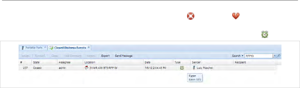
SIP-DECT OM System Manual
314
The alarm trigger “LOC-ERR-USERSTATE” is handled like SOS ( ), ManDown ( ) but no voice call
will be established.
The alarm trigger “LOC-ERR-USERSTATE” will be displayed as a Customer specific event ( ).
7.29.6 LICENSING AND SYSTEM CAPACITIES
The “User monitoring” feature does not require a specific license. However, if the OM Locating
application is used to receive the OML specific alarm trigger “LOC-ERR-USERSTATE”, the OML
application license (OM Locating Server License) must be available.
The number of monitored users is limited, as follows:
RFP OMM
• Passive monitored users: 30
• Active monitored users: 20
PC OMM
• Passive monitored users: 300
• Active monitored users: 200
An OMM system health state will be set if the number of monitored users exceeds the system
capabilities. In this case also an associated health state alarm trigger will be generated.
7.29.7 CONFIGURATION
User monitoring can be administered via the OMP.
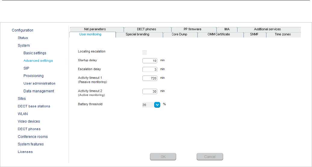
Configuration and Administration
315
7.29.7.1 “System settings: User monitoring” Menu
The following parameters can be configured on system level.
• Locating escalation: If this option enabled, the alarm trigger “LOC-ERR-USERSTATE” will be
generated by the OMM. Default setting is “off”.
• Start-up delay: The start-up delay defines the period of time the user monitoring start-up is delayed
(between 2 and 15 minutes) after failover or system start-up.
• Escalation delay: The escalation delay defines the period of time the user monitoring will wait before
the unavailable status is escalated.
• Activity timeout 1: The activity timeout 1 defines the maximum time (between 30 and 1440 minutes)
between user activities in passive monitoring mode.
• Activity timeout 2: The activity timeout 2 defines the maximum time (between 5 and 60 minutes)
between user activities in active monitoring mode.
• Battery threshold: The battery threshold defines the minimum battery load (between 0 and 100% in
steps of 5%).
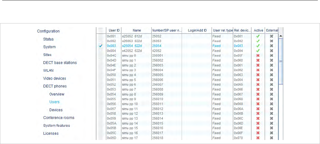
SIP-DECT OM System Manual
316
7.29.7.2 “DECT Phones” Menu
The following parameter can be configured on user level.
Monitoring mode: The user monitoring mode can be set to Off, Passive or Active. Off disables user
monitoring. Passive and Active enable user monitoring and control the mode of the DECT phone
activity status supervision. Default setting is Off.
If user monitoring is activated, the VIP option in the DECT Phones -> Users -> SIP tab for the user will
be set automatically (see page 188). The VIP option will not be reset if the user monitoring mode is set to
“Off”.
7.29.7.3 “DECT Phones -> User monitoring” Menu
The status of all monitored users is presented by the OMM in the DECT Phones -> User monitoring
menu.
7.29.7.4 User Configuration Files
The parameter “UD_UserMonitoring” controls the monitoring for a user. The parameter can be set to
“Off”, “Passive”, or “Active”.
7.29.7.5 OM IMA Application
If messages shall be sent out by the OM IMA application, the administrator must configure appropriate
alarm scenarios for the alarm triggers in the OM IMA configuration file:
• UMON-OK-USERSTATE
• UMON-WARN-USERSTATE
• UMON-ERR-USERSTATE
7.29.8 START AND FAILOVER
The availability status is set to “Unknown” at start-up.
The monitoring feature does not escalate any user status during start-up until a configurable delay of
min. 2 minutes and max. 15 minutes has elapsed.

Configuration and Administration
317
The start-up delay should be adjusted according to the system start-up. The system start-up depends on
the actual physical configuration, infrastructure components and parameter settings.
The statistic counter “Sync RFP start-up time” and “Sync Cluster start-up time” help to find an
appropriate value for the start-up delay.
As soon as the start-up delay has elapsed, the status attributes are checked and the availability status
will be determined. If the result is “Unavailable”, the status will be escalated.
The SIP registration process runs independently from the user monitoring start-up and infrastructure
start-up. Monitored users as well as other users, who have the VIP flag set, are registered first.
7.29.9 SUPPORTED DECT PHONES
The Mitel 600 DECT phone family is fully supported.1
The following states are managed independent of the DECT phone type:
• Handset assignment status (HAS)
• Handset subscription status (HSS)
• Handset registration status (HRS)
• Handset activity status (HCS)2
• SIP user registration status (SRS)
• Call diversion status (CDS)
Notes on Mitel 142d
The Mitel 142d DECT phones are supported by SIP-DECT and have an enhanced feature set compared
to GAP DECT phones. For Mitel 142d the availability status is always set to “Warning” because of the
limited feature set.
The following states are not supported:
• Handset battery state (HBS)
always set to “Unknown”
• Software Status (SWS)
always set to “Warning” to indicate the limited feature set
• Silent charging state (SCS)
always “Unknown”
If the DECT phone is put into silent charging mode then it sends a “Detach”, like it is switched off.
Comments on GAP DECT phones
GAP DECT phones are supported by SIP-DECT with a basic feature set. The availability status is always
set to “Warning” because of the limited feature set.
1 The DECT phones must be equipped with the software version that corresponds to the SIP–DECT®
release. Otherwise, functionality may be limited.
2 GAP devices do not support the active monitoring.

SIP-DECT OM System Manual
318
The following states are not supported:
• Handset battery state (HBS)
always “Unknown”
• Software Status (SWS)
always set to “Warning” to indicate the limited feature set
• Silent charging state (SCS)
always “Unknown”
GAP DECT phones do not support the active monitoring (Handset activity status /HCS). In general, there
is no guarantee for the correct interworking of the 3rd party DECT phone with SIP-DECT.
7.29.10 RESTRICTIONS
The described mechanisms check the status information in the OMM. Therefore the solution has certain
limitations.
The OMM determines the availability of the DECT device which does not necessarily represents the
availability of the user.
• It is not possible to determine whether a user actually carries his device with or not.
• The check of the availability does not include the infrastructure to which the OMM is connected (e.g.
call manager, etc.). A user appears as available even if the call manager fails.
• Feature (especially call diversion) when managed by the call server can undermine the monitoring.
• If a user is removed from the OMM, the monitoring stops without escalation. It cannot be checked if
the user belongs to an alarm scenario configured in the alarm server or any other application
scenario.
7.30 SRTP
Together with the new RFP 35/36/37 IP and 43 WLAN, SIP-DECT supports SRTP to encrypt the RTP
voice streams and SDES for the SRTP key exchange.
There are three options for SRTP:
• SRTP only: only SRTP calls will be accepted, all other will be rejected (the audio part of the SDP
contains RTP/SAVP)
• SRTP preferred: all calls will be initiated as secured, but accepted if they are not secured (the
audio part of the SDP contain RTP/AVP)
• SRTP disabled: only RTP calls will be initiated as not ciphered and incoming ciphering algorithm
will be not accepted. All communications are established unencrypted.
SIP-DECT provides the cipher suite AES_CM_128_HMAC_SHA1_80.
SRTP calls from DECT phones with DECT handover require that the SRTP functionality must be
homogenously available on all effected RFPs. To allow mixed installations with the older RFP types
32/34 and 42 WLAN, the SRTP feature can be enabled or disabled per site. Whereby, SRTP can only be
activated on sites with only RFPs 35/36/37/43 included.

Configuration and Administration
319
IMPORTANT : A handover of an S RTP call to a site with disabled SRTP will drop the
call.
IMPORTANT : SDES specifies as key exchange method the negotiation over SDP
included in the SIP signaling. Therefore, we recommend to use TLS to encrypt the
key exchange.
IMPORTANT : Please enable “SRTP = only” mode exclusively when all communication
can be established with SRTP. Depending on the call server some features or
gateways may not offer SRTP.
7.31 SIP OVER TLS
The transport protocol modes “TLS” or “Persistent TLS” enable a private and authenticated signaling,
including safe key exchange for SRTP encryption.
The transport protocol and all further security settings can be set via the OMP System -> SIP-> Security
tab and the OMP System -> SIP-> Certificate Server tab.
The following parameters can be set:
General
• Transport protocol: The protocol used by the OMM to send/receive SIP signaling. Default is “UDP”.
• Persistent TLS Keep alive timer active: When enabled and “Persistent TLS” is selected as transport
protocol, the OMM sends out keep alive messages periodically to keep the TLS connection open.
• Persistent TLS Keep alive timer timeout: Specifies the time, in seconds, between keep-alive
messages sent out by the OMM. Valid values are “10” to “3600”. Default is “30” seconds.
• Send SIPS over TLS active: When enabled and “TLS” or “Persistent TLS” is selected as transport
protocol, the OMM uses SIPS URIs in the SIP signaling. Default is “ON”.
• TLS authentication: When enabled and “TLS” or “Persistent TLS” is selected as transport protocol,
the OMM validates the authenticity of the remote peer via exchanged certificates and the configured
“Trusted certificates”. Default is “ON”.
• TLS common name validation: When enabled and “TLS authentication” is selected the OMM
validates the “Alternative Name” and “Common Name” of the remote peer certificate against the
configured proxy, registrar and outbound proxy settings. If there is no match an established TLS
connection will be closed immediately.
PEM file import
• Allows the manual import of Trusted, Local Certificates and a Private Key in PEM file format.
The following parameters can only be read and should ease the handling of certificates:
• Trusted Certificates: The number of imported trusted certificates.
• Local Certificate chain: The number of imported certificates in the local certificate chain.
• Private Key: Is a private key imported or not.

SIP-DECT OM System Manual
320
Certificate server
Optionally is also an automatic import of Trusted, Local Certificates and a Private Key files from an
external server possible. This can be configured on the “Certificate Server” tab.
The following parameters allow an automatic import:
• Active: Enable or disable the automatic import.
• Protocol: Selects the preferred protocol (FTP, TFTP, FTPS, HTTP, HTTPS, SFTP)
• Server: IP address or name of the server
• User Name / Password / Password confirmation: The server account data if necessary.
• Path: The path on the server to certificate files.
• Trusted certificate file: The name of the PEM file on the given server including the trusted
certificates.
• Local certificate file: The name of the PEM file on the given server including the local certificate or a
certificate chain.
• Private key file: The name of the PEM file on the given server including the local key.
7.31.1 CERTIFICATES
The use of “TLS” or “Persistent TLS” requires the import of certificates to become operational.
Item When Needed Setting
Trusted
Certificates
For TLS and Persistent
TLS
A PEM file with a list of all (self-signed) CA
certificates needed to verify remote certificates. May
also contain trusted intermediate certificates instead
of or in addition to self-signed certificates
In many cases there is only one certificate in this list:
The self-signed certificate which is used by the SIP
proxy and registrar or which was used to sign that
certificate.
Local
Certificate
For TLS: Always
For Persistent TLS: Only
if the server verifies the
client certificate
A PEM file with the OMM’s certificate chain
Private Key A PEM file with the OMM’s private key
All certificates and keys must be provided as X.509 certificates in PEM file format. They must use the
RSA algorithm for their keys and signatures and MD5 or SHA-1 for their hashes.
Although PEM files usually contain a textual description of the certificate, only the Base64-encoded
portions between
-----BEGIN CERTIFICATE-----
and
-----END CERTIFICATE-----

Configuration and Administration
321
are actually evaluated. However, the files can be uploaded to the OMM with their full content.
There are two sets of certificates which can be set up in the OMM, which are described in the following
sections.
Trusted Certificates
The trusted certificates are used to verify the signatures of certificates sent by remote hosts. The
corresponding PEM file may contain multiple certificates. Their order is not relevant. Certificates are
searched in the trust store according their subject name, the key identifier (if present), and the serial
number as taken from the certificate to be verified.
Local Certificates
The local certificate or local certificate chain is sent to remote hosts for authentication.
In corresponding PEM files the host certificate must be in the first position, followed by intermediate
certificates if applicable. The last certificate is the self-signed root-certificate of the CA. The root
certificate may be omitted from the list, as the remote host must possess it anyway to verify the validity.
This means that if there are no intermediate certificates, this file may contain only one single certificate.
7.31.2 PRIVATE KEY
The Private Key is also contained in a PEM file. The Local Certificate must match to the Private Key.
Although PEM files may contain a textual description of the key, only the Base64-encoded portions
between
-----BEGIN RSA PRIVATE KEY-----
and
-----END RSA PRIVATE KEY-----
is actually evaluated. However, the file can be uploaded to the OMM with its full content.
7.31.3 TLS TRANSPORT MODE
The OMM distinguishes the both TLS transport modes TLS and Persistent TLS.
When the OMM is configured to use TLS (Transport protocol: TLS), TLS connections to remote peers,
e.g. SIP proxies and registrars, are connected as needed. For TLS connections initiated by the OMM, it
is a TLS client. If a remote peer sets up a TLS connection, the OMM is the TLS server. Connections are
closed when they have not been in use for a certain time. The terms server and client refer to TLS
connections below, not to SIP transactions.
The OMM always verifies the server certificate when it sets up an outgoing connection and it verifies the
client certificate on incoming connections. Therefore following configuration parameters must be set for
this mode: Trusted Certificates, Local Certificate and Private Key.
When the OMM is configured to use persistent TLS (Transport protocol: Persistent TLS), it sets up TLS
connections to SIP Servers and keeps them connected. When a connection is closed for whatever
reason, the OMM tries to re-establish it immediately. It does not accept incoming connections from
remote ends. Thus the OMM is always TLS client when Persistent TLS is in use.
The advantage of Persistent TLS is a faster call setup time and lower processing power needed on both
sides.

SIP-DECT OM System Manual
322
The OMM always verifies the server certificate, therefore following configuration parameters must be set
for this mode: Trusted Certificates
If the server verifies the client certificate, additionally Local Certificate and Private Key must be set.
7.31.4 VERIFICATION OF REMOTE CERTIFICATES
When “TLS authentication” is “ON”, a remote certificate is verified by the OMM as follows:
The signature of the certificate is checked with the public key of the signing certificate. The certificate
chain is checked until a Trusted Certificate is found. If self-signed certificate is found which is not trusted,
the verification fails.
The current time must be in the validity period of the certificate. For this mechanism a correct system
time must be provided (e.g. NTP).
If one or more of these checks fail, the TLS connection will be closed.
Please note: All certificates are only valid for a limited time given by the issuer. As soon as
the validity is expired no further communication is possible. The certificates must be
replaced before to prevent a breakdown of call services.
When “TLS authentication” is “OFF”, the OMM verifies the remote certificates and logs any failure but the
established TLS connection will not be closed in case of verification failures.
IMPORTANT : To prevent man-in-the-middle attacks we recommend not to disable the
“TLS authentication” in unsecure environments. We recommend setting “TLS
authentication” and “TLS common name validation” to “ON” in any unsecure
environments for the best security.
7.31.5 ADDITIONAL SECURITY CONSIDERATIONS
For highest security requirements there are additional considerations to be taken into account when
enrolling an OpenMobility system.
To prevent manipulations during the initial upload of certificates and keys to the OMM completely, this
should be done in a small private network without a physical connection to an insecure network.
IMPORTANT : To prevent manipulation of certificates and keys in unsecure
environments we recommend not to use the automatic import of certificates and
keys. Especially the unsecure protocols TFTP, FTP and HTTP must be avoided. It is
also recommended to protect the selected protocol with a login to prevent
unauthorized access to the private key file.
Furthermore, it is important that the root and administrator passwords of the OpenMobility system are
safe, because with these passwords an attacker could change the configuration to manipulate the
system in various ways.
Although all keys and certificates in the database are encrypted, an automated database backup or
download could be a security leak if the network, transport protocol or servers used are not protected
against manipulations.

Configuration and Administration
323
7.32 DECT ENHANCED SECURITY
Security aspects in the DECT standard have been improved after concerns were raised in the market in
recent years. Therefore various enhancements have been introduced.
The usage of many security features, which were already available in the DECT standard (respectively
GAP) from the beginning, was left optional for the devices. These mechanisms became mandatory
together with CAT-iq. Almost each of these functionalities was present and used within SIP-DECT right
from the start.
Furthermore, some new features have been added to GAP:
• Encryption of all calls (not only voice calls)
• Re-keying during a call
• Early encryption
Each procedure brings additional guarantee on security and is an integral part of the SIP-DECT solution.
The feature set can be enabled or disabled per site. This distinction is necessary due to the fact, that
enhanced security is available with RFPs 35/36/37/43 only.
From release 5.0 on, when DECT enhanced security is enabled, every connection will be encrypted, not
only voice calls, but also such as service calls (e.g. list access) or messaging.
Additionally, the cipher key used for encryption during an ongoing call is changed every 60 seconds.
Finally, every connection is encrypted immediately upon establishment to protect the early stages of the
signaling such as dialing or CLIP information.
DECT enhanced security is only supported together with Mitel 602 DECT phones. Older terminals (e.g.
6x0d or 142d) or GAP phones will still operate as ever, but not provide the new security mechanisms.
7.33 MIGRATION OF RFP SL35 IP FROM SIP-DECT LITE 3.1 TO SIP-
DECT 6.1
The SIP-DECT Lite solution realized a single-cell DECT network that offered only limited radio coverage
and was operated with one RFP SL35 IP. The SIP-DECT Lite solution was part of the SIP-DECT product
family that offered larger radio coverage by realizing multi-cell DECT networks with up to 2.56 RFPs.
You can integrate the RFP SL35 IP to a multi-cell SIP-DECT network. The migration from SIP-DECT
Lite to the current release of the standard SIP-DECT system is supported. During the migration the SIP-
DECT Lite software is replaced by the standard SIP-DECT software on the RFP SL35 IP and a reset to
the factory setting is performed. All configuration data are removed from the base station.
The following migration process must be performed.
Precondition: Unique UNLOCK.xml file is available for the specific RFP SL35 IP.
1 Remove the USB flash memory from the RFP SL35 IP and plug it into your computer.
2 Copy the unlock.xml file onto the USB flash memory.
3 Copy the standard SIP-DECT SW (iprfp3G.dnld) onto the USB flash memory of the RFP.
4 Check if the following files are on the USB flash memory (no other files should be on the USB flash
memory except SIP-DECT™ Lite DB backup field “omm_conf.txt” which is not relevant).
a. PARK.xml
b. UNLOCK.xml
c. iprfp3G.dnld

SIP-DECT OM System Manual
324
5 Remove the USB flash memory from your computer and plug into the RFP SL35 IP.
6 The migration process starts automatically after plugging the USB flash memory into the RFP.
7 Wait for the RFP reboot and start-up. Do not interrupt the electric power during this process.
8 The SW update for RFPs in standard SIP-DECT installations are provided by other means than to
copy the SW on the USB flash memory. Therefore the iprfp3G.dnld must be removed from the USB
flash memory.
Make sure that the PARK.xml and UNLOCK.xml remain on the USB flash memory.
9 Also after the migration, make sure that the USB flash memory is always plugged in the RFP.
10 Now, the RFP SL35 IP has the standard SIP-DECT SW and the UNLOCK.xml file and can be
operated in standard SIP-DECT installations. Please follow the standard procedures to setup a SIP-
DECT installation.

Maintenance
325
8 MAINTENANCE
8.1 SITE SURVEY MEASUREMENT EQUIPMENT
If a SIP-DECT installation must be planned, a sufficient distribution of DECT base stations that meets the
requirements for reliable synchronization and connectivity to the DECT phones is necessary. The site
survey kit may help you. It comprises:
• One measuring RFP with its own power supply.
• A tripod and a battery for the RFP.
• Two reference DECT phones with chargers.
• Battery chargers.
• Optional a measuring DECT phone which can monitor other makers DECT radio sources.
8.2 CHECKING THE MITEL HANDSET FIRMWARE VERSION
You can display the version information of a Mitel 600 or Mitel 142d DECT phone with a few keystrokes.
Check the firmware version to determine whether an update is required to overcome any user issues.
1 Press the Menu soft key.
2 Select System (only to highlight).
3 Press OK.
4 Select Version Number.
5 Press OK.
The display shows the software and the hardware version of the Mitel DECT phone.
8.3 DIAGNOSTIC
8.3.1 MITEL DECT PHONE SITE SURVEY MODE
You can switch a Mitel 600 or Mitel 142d DECT phones into “site survey mode” with a few keystrokes. In
this mode the phone will display the RFPs and the actual field strength of the receiving signal in dBm.
1 Press the Menu soft key.
2 Enter the following key sequence “***76#” (Mitel 600 ) or “R***76#” (Mitel 142d).
3 Select Site Survey.
4 Press OK.
5 To leave the site survey mode, switch the phone off and on again.
The following display is shown on the Mitel DECT phone:
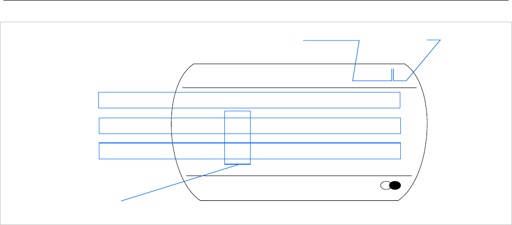
SIP-DECT OM System Manual
326
Menu
Phonebook
RFPI 10FFF21 02
FE PP: FP:
-dBm 50 57 50
RPN 02 01 00
PARK: 1F-10-FF-F0-21
RFP ID: 02*
RFP ID: 02*
*The ID of RFP to which the PP is currently associated to.
Frame error
Field strength
RFP ID
In this example the DECT phone is currently connected to the RFP with the number 02. The RFPs 01
and 00 are also visible. The number “10FFF221 02” on the upper right side refers to the PARK (Example
1F-10-F2-21) of the SIP-DECT system and to the RFP to which the phone is currently connected to.
8.3.2 MITEL HANDSET AUTO CALL TEST MODE
You can switch a Mitel 600 or Mitel 142d DECT phones into “auto call test mode” with a few keystrokes.
In this mode the phone will call a specified number cyclically. You can use this feature to generate traffic
for test purposes. This mode is also active if the phone is on the charger.
1 Press the Menu soft key.
2 Enter the following key sequence “***76#” (Mitel 600 ) or “R***76#” (Mitel 142d).
3 Select Auto Call Test.
4 Press OK.
5 Enter the phone number to call.
6 Press OK.
7 Enter a number of seconds between two calls.
8 Press OK.
9 Enter a number of seconds a call shall be active.
10 Press OK. The test will be started automatically.
11 To stop the test, switch the phone off and on again.
8.3.3 MITEL HANDSET AUTO ANSWER TEST MODE
You can switch a Mitel 600 or Mitel 142d DECT phone into “auto answer test mode” with a few
keystrokes. In this mode, the phone answers incoming calls automatically. You can use this feature
together with phones in the “auto call test mode” (see section 8.3.2) for test purposes. This mode is also
active if the phone is on the charger.
1 Press the Menu soft key.
2 Enter the following key sequence “***76#” (Mitel 600 ) or “R***76#” (Mitel 142d).
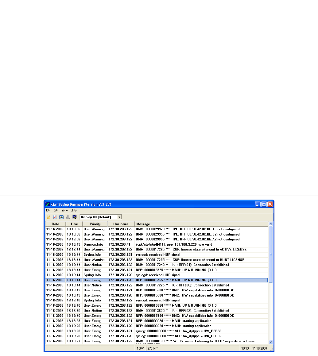
Maintenance
327
3 Select Auto Answer.
4 Press OK.
5 Enter a number of seconds the phone shall ring before it will answer the call.
6 Press OK.
7 Enter a number of seconds a call shall be active.
8 Press OK. The test will be started automatically.
9 To stop the test, switch the phone off and on again.
8.3.4 SYSLOG
The OpenMobility Manager and the RFPs are capable of propagating Syslog messages conforming to
RFC 3164 (see /13/). This feature together with the IP address of a host collecting these messages can
be configured.
Syslog must be enabled by:
• DHCP using the public options 227 and 228.
• Setting the syslog daemon server and port via the web interface.
To set up the syslog via DHCP or the OM Configurator has the advantage that syslogs are available in
earlier states of the RFP startup.
The level of syslog messages in the default state allows the user to have control over the general system
state and major failures.

SIP-DECT OM System Manual
328
8.3.5 SSH USER SHELL
Each RFP offers a lot of commands within the SSH shell. Most of them are useful for diagnostics and
may help experts to resolve failures.
Note: Some commands can harm the system operation.
The SSH access of an RFP is open if
• the RFP is connected to an OMM and the “Remote Access” is switched on or
• the RFP is not connected to an OMM.
To activate the SSH access of an RFP that has a connection to an OMM, enable the Remote access
checkbox on the OMM System settings web page (see section 5.4.1.1). In the OMP, the SSH access is
activated/deactivated in the General tab of the System -> Basic settings menu (see section 6.5.1).
8.3.5.1 Login
To log into the SSH user shell:
1 Open an SSH session to the IP DECT base station with the “Full access” user name.
2 Enter the password for the “Full access” account (see also 7.17.1).
The output should look like:
Welcome to IP RFP OpenMobility SIP Only Version 2.1.x
last reset cause: hardware reset (Power-on reset)
omm@172.30.206.94's password:
omm@172.30.206.94 >
8.3.5.2 Command Overview
Type help to get a command overview:
Command Description
exit,quit,bye Leave session
ommconsole OMM console
ip_rfpconsole RFP console
rfpm_console RFP manager console
wlan_console WLAN console
ics_console ICS console
ldb View / set local configuration (OmConfigurator)
setconsole Duplicate messages to console
noconsole Do not duplicate messages to console
dmesg Messages from last boot
logread Last messages
su Switch to user root

Maintenance
329
ping Well known ping
traceroute Well known traceroute
free Well known free
ps Well known ps
top Well known top
ifconfig Well known ifconfig
uptime Well known uptime
reboot Well known reboot
date Well known date (time in UTC)
8.3.5.3 OMM Console On Linux Server
You can call the OMM console on the Linux server which runs the OMM using the “ommconsole”
command. Log on as root as it is necessary to install and/or update OMM.
IMPORTANT : If you not login as root to open the OMM console then the path to
ommconsole is not set and you must enter the whole path “/usr/sbin/ommconsole”
to start the OMM console.
8.3.5.4 RFP Console Commands
If you type ip_rfpconsole you are able to use the following commands on each RFP:
Command Description
? Displays Command Help Table
bt Bluetooth commands
confmix Displays status of conference mixer
help Displays Command Help Table
logger Send a string to the syslog daemon
deftrc Resets all trace settings to default
runtime Reports the process runtime
mem Show memory and heap
exit Leave this console
heap Shows heap buffer statistics
heapcheck Verifies the guard space of all via doss allocated buffer. Heap
functions are locked during check
heapdetails Print detailed heap usage
jpeg Jpeg helper commands
lu10 Lu10 SDU <-> PDU converter
mclose Close a media channel

SIP-DECT OM System Manual
330
Command Description
mconf Configure IP settings for a media channel
media Display state of media channels
mopen Open a media channel
mroute Display media routes
mstart Start a media channel
mstop Stop a media channel
mswo Codec switch over for an active call
mtime Display media time statistics
mutex Lists all created MXP mutexes
omms Shows connection status to OMM(s)
otpdbCheck Check all OTP pages for valid elements
queues Lists all created MXP queues
reset Resets the IPRFP application
resume Resume bmc activity
sem Lists all created MXP semaphores
signals Print signal dwell time in queues
spy Set/display spy levels: [ <key #> <level #> ]
suspend Suspend bmc activity
tasks Lists all running MXP tasks
tickres Print tick resolution
timer Print running timer
video Video commands
Please note: The “spy” command enables you to increase the level of syslog messages.
This should be only used by instructions of the support organization because it can harm
the system operation.
8.3.5.5 OMM Console Commands
If you have opened the session on the OMM RFP and you type “ommconsole”, you are able to use the
following OpenMobility Manager (OMM) related commands:
Command Description
? Displays Command Help Table
adb Automatic DB export and import (ADB) console
axi AXI commands
axic Task console for AXI command processing of provisioning files

Maintenance
331
Command Description
cert Certificate import console
cmi CMI commands
cnf Show configuration parameters
cron Display pending cron jobs
help Displays Command Help Table
logger Send a string to the syslog daemon
deftrc Resets all trace settings to default
dlc DECT Data Link Control
dm Download Over Air Manager
dsip DSIP commands
epr External provisioning task (EPR) console and dynamic users console
runtime Report the process runtime
mem Show memory and heap
exit Leave this console
gmi DECTnet2 Inter Working Unit
hcm Handset configuration management task (HCM) console
heartbeat Configure heartbeat mechanism for IP-RFPs
ima IMA commands
inspect Display information of a user
ipc Display socket communication
ipl Display connected RFPs
iplfilter Configure which RFPs spy messages are generated for
lic LIC commands
loc Info about locating extension
mon Toggle monitor functionality
msm Display states within MediaStreamManagement
msmtrc Display / modify list of traced DECT phoneNs
mutex List all created MXP mutexes
nwk DECT network layer
prov Prov-related commands
queues List all created MXP queues
rcmd Remote command on RFPs shell
rfp Radio Fixed Part Control
rfpd Radio Fixed Part Debug
rfps Radio Fixed Part Statistic

SIP-DECT OM System Manual
332
Command Description
rping Request one or more RFPs to ping a host
rspy Remote configure spy levels on IP-RFPs
rsx Toggle RSX debug port on RFPs
rtt Set event flag for high RTT values / clear values
sem List all created MXP semaphores
spy Set/display spy levels: [ <key #> <level #> ]
standby Displays redundant OMMs
stat Statistic
sync Commands for RFP synchronization
sysdump Initiate system dump
tasks List all running MXP tasks
tickres Print tick resolution
trc Back trace task
tzone Time zone commands
uds UDS commands
umo UMO commands
upd Display update status of RFPs
update Force all connected RFPs to search for new software
uptime Display OpenMobility Manager uptime
ver Version information
video Command for video devices
wlan Display states within Wireless LAN Management
xml XML browser task (XML) console
xsc XSC commands
Please note: The “spy” command enables you to increase the level of syslog messages
especially for subsystems of the OMM. This should be only used by instructions of the
support organization because it can harm the system operation.
8.3.6 CORE FILE CAPTURING
Fatal software problems may result in memory dumps, so called core files. These core files are helpful in
analyzing the problem that caused the abnormal termination of the program. The IP RFP is capable of
transferring the core files to a remote fileserver. Without any special configuration the files are
transferred to the TFTP server that is used to get the system software. The path used is the directory of

Maintenance
333
the boot image. These two configuration items are retrieved from DHCP or via local configuration using
the OM Configurator.
You can configure the URL to a writable directory via the OMM (see section 5.4.1.12) or through the
“OM_CoreFileSrvUrl” variable in the ipdect.cfg configuration files.
Please note: The server must allow writing new files (not typically enabled by default).
8.3.7 DECT MONITOR
Please note: The DECT Monitor has been replaced by OMP but the DECT Monitor can still
be used without warranty for SIP-DECT installations with a standard PARK and up to 256
RFPs all within paging area 0.
For better error detection in the SIP-DECT system the DECT Monitor can be used. The DECT Monitor is
an MS Windows based stand-alone program. It provides the possibility to give a real-time overview of
the current IP DECT base station and telephone states in the SIP-DECT system.
The following features are provided by the DECT Monitor:
• Reading out of the DECT configuration of an SIP-DECT system.
• Configuration can be stored in an ASCII file.
• Display of DECT transactions IP DECT base station <–> telephone in clear tabular form with
highlighting of handover situations. Real-time display.
• Display of further events concerning the status or actions of IP DECT base stations and telephones of
the SIP-DECT system.
• All events can also be recorded in a log file.
• Display of the synchronization relations between the RFPs.
• Monitoring of systems with up to 256 IP DECT base stations and 512 DECT phones.
• Reading out and display of IP DECT RFP statistics data, either for a single IP DECT RFP or for all IP
DECT RFPs.
• Display of DECT central data of the SIP-DECT system.
The DECT Monitor program can only be used when the DECT monitor checkbox is activated on the flag
in the OMM System settings web page.
Please note: Because of security, the DECT monitor flag is not stored permanently in the
internal flash memory of the OMM/RFP. After a reset the DECT monitor flag is disabled.
The DECT monitor program is used together with the SIP-DECT system. When the program is started,
the user is requested to enter the IP address of the IP DECT RFP or the server running the OpenMobility
Manager (OMM) software.
There can be several reasons for an unsuccessful link establishment:
• Operation of DECT monitor is not enabled inside the OMM. Use the OMM web service to enable
DECT monitor operation.
• IP address is not correct. It must be the address of the RFP the OMM is running on.
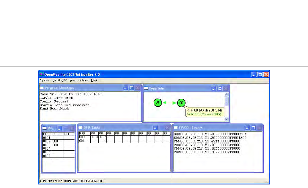
SIP-DECT OM System Manual
334
• A link routed to the RFP is not supported.
The program displays the IP address which was used last time. When the program is started, a link to
the OMM is automatically established and the program window shows all user configured child windows
and tables. When all links have been established, the DECT data of the system are automatically read
out and entered in the tables “RFP-Table” and “DECT phone-Table”. This procedure is called “Config
Request”.
Next, the defined trace options (Event Mask) are sent to the OMM. The options which are sent to the
OMM are always those which were active the last time the program was exited.
If the trace option “Transaction establish/release” is activated, the OMM will deliver all existing
transactions.
Following this, the OMM system delivers the desired trace data. The user can either communicate with
the program interactively (see below) or he can simply activate a log file in which to record the data.
Following this initialization, the user can carry out the following modifications:
• The trace settings can be modified using the menu item Options-Event Mask. Transmission to the
OMM takes place after confirmation of the settings with OK.
• A Config Request can be sent again to the OMM.
• A log file can be activated.
• By means of various dialogs, the configuration data of the telephones, RFPs and control modules can
be displayed and stored in ASCII files.
The following information is displayed dynamically in the tables:
• Transactions between telephone and DECT system. These are displayed in both tables. Simple
transactions are displayed in black on a white background; during handover, both transactions
involved are displayed in white on a red background.
• The Location Registration and Detach events are displayed in the tables for approx. 1-2s after their
occurrence (light green background), if possible. There is no display in the FP table if there is no
column free for display. If the event has already been displayed, it can be overwritten at any time. The
events are not displayed if they occur during an on-going transaction. Irrelevant of whether the events
are displayed in the tables, they are always entered in the FP/DECT phone-Events window and in
the log file (provided that this is open).
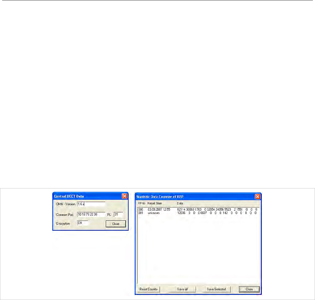
Maintenance
335
The following color scheme is used for display of the RFPs in the RFP table:
• RFP gray-blue: IP DECT base station is not active (not connected or disturbance).
• RFP black: IP DECT base station is active.
The data of an RFP are displayed in a dialogue box after clicking on the respective RFP field in the RFP
table. The statistics data of the RFP can be called up from this dialogue box.
The following color scheme is used for display of the telephone in the DECT phone table:
• DECT phone black: Handset is enrolled. It is assumed that the telephone can be reached.
• DECT phone blue: Handset can presumably not be reached. Detach was received, or when an
attempt was made to reach a telephone, the DECT phone did not answer.
• DECT phone gray blue: Handset not enrolled.
The data of a telephone are displayed in a dialog box after clicking on the respective telephone field in
the FP table.
The Sync Info child window contains all IP DECT base stations and shows their synchronization and
relation states to each other. Selecting the IP DECT base stations with the right mouse button, the user
can change visibility views and can even force a resynchronization of an IP DECT base station.
There are several optional child windows selectable. They are all listed below and give some more
information about the SIP-DECT systems. Mostly they are statistics and for internal use only.
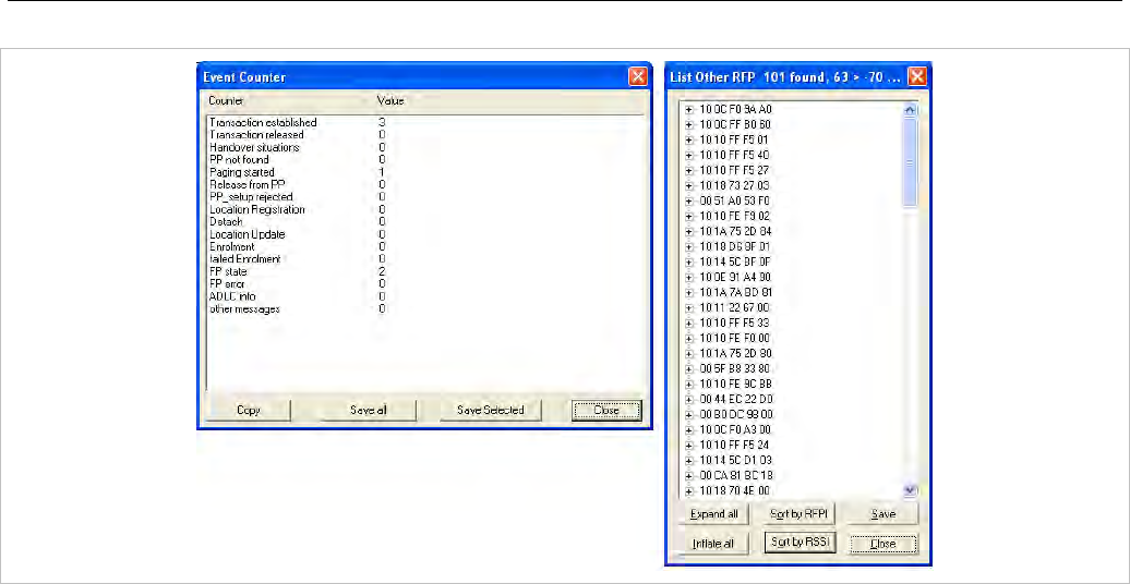
SIP-DECT OM System Manual
336

Safety Information
337
9 SAFETY INFORMATION
9.1 CE MARKING
This certifies the conformity of the product with the regulations which apply in accordance with the
directive R&TTE 1999/5/EC.
For a copy of the original signed declaration (in full conformance with EN45014) please contact the
Regulatory Approvals Manager at Mitel Networks Ltd., Castlegate Business Park, Portskewett,
Monmouthshire, NP26 5YR, United Kingdom.
9.2 COMMUNICATIONS REGULATION INFORMATION
The regulation information in this section applies to the following supported DECT base stations:
• RFP 32 IP
• RFP 34 IP
• RFP 35 IP
• RFP 36 IP
• RFP 37 DRC
9.2.1 FCC NOTICES (U.S. ONLY)
This device complies with part 15 of the FCC Rules. Operation is subject to the following two conditions:
(1) This device may not cause harmful interference, and (2) this device must accept any interference
received, including interference that may cause undesired operation.
Modifications not expressly approved by this company could void the user's authority to operate the
equipment.
NOTE: This equipment has been tested and found to comply with the limits for a Class B digital device,
pursuant to Part 15 of the FCC Rules. These limits are designed to provide reasonable protection
against harmful interference in a residential installation. This equipment generates, uses and can radiate
radio frequency energy and, if not installed and used in accordance with the instructions, may cause
harmful interference to radio communications. However, there is no guarantee that interference will not
occur in a particular installation. If this equipment does cause harmful interference to radio or television
reception, which can be determined by turning the equipment off and on, the user is encouraged to try to
correct the interference by one or more of the following measures:
• Reorient or relocate the receiving antenna.
• Increase the separation between the equipment and receiver.
• Connect the equipment into an outlet on a circuit different from that to which the receiver is
connected.
• Consult the dealer or an experienced radio/TV technician for help.

SIP-DECT OM System Manual
338
9.3 HEALTH AND SAFETY
9.3.1 EXPOSURE TO RADIO FREQUENCY (RF) SIGNALS:
The wireless phone is a radio transmitter and receiver. It is designed and manufactured not to exceed
the emission limits for exposure to radio frequency (RF) energy set by the Federal Communications
Commission (FCC) of the U.S. Government. These limits are part of comprehensive guidelines and
establish permitted levels of RF energy for the general population. The guidelines are based on the
safety standards previously set by both U.S. and international standards bodies. These standards
include a substantial safety margin designed to assure the safety of all persons, regardless of age and
health.
This device and its antenna must not be co-located or operating in conjunction with any other antenna or
transmitter.
The radiating element of the RFP should be installed during operating at a separation distance greater
than 20 cm between user and device. The device complies with the requirements for routine evaluation
limits.
9.3.2 INDUSTRY CANADA (CANADA ONLY)
Operation of this device is subject to the following two conditions: (1) this device may not cause
interference, and (2) this device must accept any interference, including interference that may cause
undesired operation of the device.
Privacy of communications may not be ensured when using this telephone.
Exposure to Radio Frequency (RF) Signals:
The wireless phone is a radio transmitter and receiver. It is designed and manufactured not to exceed
the emission limit for exposure to radio frequency (RF) energy set by the Ministry of Health (Canada),
Safety Code 6. These limits are part of comprehensive guidelines and established permitted levels of RF
energy for the general population. These guidelines are based on the safety standards previously set by
international standard bodies. These standards include a substantial safety margin designed to assure
the safety of all persons, regardless of age and health.
This device and its antenna must not be co-located or operating in conjunction with any other antenna or
transmitter.
The radiating element of the RFP should be installed during operating at a separation distance greater
than 20 cm between user and device. This device complies with the requirements for routine evaluation
limits.
9.4 INFORMATIONS RÉGLEMENTAIRES EN MATIÈRE DE
COMMUNICATIONS
Les informations dans cette section concerne les suivantes stations radio :
• RFP 32 IP
• RFP 34 IP
• RFP 35 IP
• RFP 36 IP
• RFP 37 DRC

Safety Information
339
9.4.1 NOTES FCC (USA UNIQUEMENT)
Cet appareil est conforme à la partie 15 des règles FCC. Son exploitation est soumise aux deux
conditions suivantes: (1) Cet appareil ne doit causer aucune interférence dommageable et (2) cet
appareil doit tolérer toute interférence reçue à l'inclusion des interférences susceptibles de causer une
opération non désirée. Les modifications non expressément agrées par cette entreprise pourraient
rendre caduque l'habilitation de l'utilisateur à exploiter cet équipement.
NOTA: Cet équipement a été testé et jugé conforme aux limitations pour un appareil numérique de
classe B en vertu de la partie 15 des règles FCC. Ces limitations ont été conçues pour garantir une
protection raisonnable contre les interférences dommageables dans les installations résidentielles. Cet
équipement génère, utilise et peut rayonner des ondes radio et peut causer des interférences
dommageables dans les communications par radio s'il n'est pas installé et utilisé conformément aux
instructions. Cependant, l'absence d'interférences dans une installation particulière n'est pas garantie. Si
cet équipement perturbe de façon importante la réception de la radio ou de la télévision (interférences
qui peuvent être déterminées en arrêtant et en remettrant l'appareil en marche), l'utilisateur est invité à
tenter de corriger les interférences en prenant une ou plusieurs des mesures suivantes:
• Réorienter ou déplacer l'antenne de réception.
• Éloigner l'équipement du récepteur.
• Raccorder l'équipement à une prise d'un circuit différent de celui auquel est raccordé le récepteur.
• Consulter le revendeur ou un technicien radio/TV.
9.5 SANTÉ ET SÉCURITÉ
9.5.1 EXPOSITION AUX SIGNAUX RADIO (RF)
Votre téléphone sans fil est un émetteur-récepteur radio. Il a été conçu pour ne pas dépasser les
limitations en matière d'exposition aux ondes radio établies par la Federal Communications Commission
(FCC) du gouvernement des États-Unis. Ces limitations font partie de directives complètes et établissent
des niveaux admissibles d'énergie RF pour l'ensemble de la population. Ces directives sont basées sur
des normes de sécurité établies par des organes de normalisation américains et internationaux. Ces
normes intègrent une importante marge de sécurité censée garantir la sécurité de toute personne, quels
que soient son âge et son état de santé.
Cet appareil et son antenne ne doivent pas être installés ou exploités conjointement avec d'autres
antennes ou émetteurs.
L'élément rayonnant de la station radio doit être installé à une distance de 20 cm ou plus entre
l'utilisateur et l'appareil. Cet appareil est conforme aux exigences relatives aux limites d'évaluation de
routine .
9.5.2 INDUSTRIE CANADA (CANADA UNIQUEMENT)
L'exploitation de cet appareil est soumise aux deux conditions suivantes: (1) Cet appareil ne doit causer
aucune interférence et (2) cet appareil doit tolérer toute interférence reçue à l'inclusion des interférences
susceptibles de causer une opération non désirée.
La confidentialité des communications risque de ne pas être garantie lorsque vous utilisez ce téléphone.

SIP-DECT OM System Manual
340
Exposition aux ondes radio (RF):
Votre téléphone sans fil est un émetteur-récepteur radio. Il a été conçu pour ne pas dépasser les
limitations en matière d'exposition aux ondes radio émises par le Ministère de la Santé (Canada,) Code
de sécurité 6. Ces limitations font partie de directives complètes et établissent des niveaux admissibles
d'énergie RF pour l'ensemble de la population. Ces directives sont basées sur des normes de sécurité
établies par des organes de normalisation internationaux.
Ces normes intègrent une importante marge de sécurité censée garantir la sécurité de toute personne,
quels que soient son âge et son état de santé.
Cet appareil et son antenne ne doivent pas être installés ou exploités conjointement avec d'autres
antennes ou émetteurs.
L'élément rayonnant de la station radio doit être installé à une distance de 20 cm ou plus entre
l'utilisateur et l'appareil. Cet appareil est conforme aux exigences relatives aux limites d'évaluation de
routine .

Appendix
341
10 APPENDIX
This Appendix contains additional information and examples for configuring your SIP-DECT system.
10.1 PRE-CONFIGURATION FILE RULES
The following file format description can be used to administrate the RFP and DECT phone configuration
with external applications, e.g. an external configuration management tool or a PBX communications
system.
The framework of the text file follows strictly defined rules. The main framework is divided in two parts:
1 An instruction section is used to drive a generic data creation for those fields not filled within data
sequence section.
2 A data sequence section defines data record fields. Each of them is explicitly set.
Layout rules in detail are:
• Comments start with “#”.
• Each record is terminated by the regular expressions “\r” or “\n”.
• Instruction settings are made like: <tag> = <value>.
• Data sequence sections start with the key word “data_sequence”. This key word is mandatory for file
processing to proceed. All instructions must be written before this row.
• Data sequence record fields are separated by colon “;”. Colons have also to be set for empty fields if
at least one follows which is not empty. Otherwise a position mismatch of fields will occur.
• If fields have several values assigned (that may be true for a few local RFP configuration fields like
“ntp_address”), they must be separated by comma “,”.
Notes:
• Because data sequence fields are separated by a colon, the content of that section can be generated
by a *.csv export of Excel Sheet and copied into the configuration file.
• Instructions are only processed on those fields that are left empty within the data sequence section.
10.1.1 DECT PHONE CONFIGURATION FILE (OMM DATABASE)
10.1.1.1 Supported Instructions
Instruction Explanation
start_number Numbers can be generated automatically. This instruction defines
the start value.
no_of_number If “start_number” is given, this instruction defines the maximum of
numbers which are generated.
ac (authentication code) If set to “number”, “ac” will be equal to number.
If a value is advised, it will be taken as a start number which will
be increased for each new record.
additional_pin
sip_user
sip_pw
sos_number If these instructions are set, the value will be taken as default
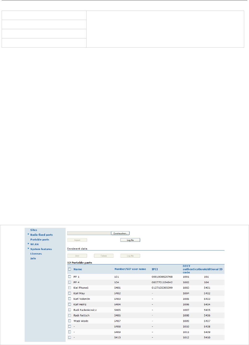
SIP-DECT OM System Manual
342
mandown_number
value for the empty corresponding field within the data sequence
section records.
SOS/Mandown denote the user specific numbers. The Locatable,
Localization, and Tracking flags are ignored by Web import.
locatable
localization
tracking
10.1.1.2 Data Section Fields
The data section contains the following field order:
1 Number
2 Name
3 AC
4 IPEI
5 Additional ID
6 Sip user name
7 Sip password
8 SOS number
9 Mandown number
10 Locatable (ignored by Web import and always set to “inactive”)
11 Localization (ignored by Web import and always set to “inactive”)
12 Tracking (ignored by Web import and always set to “inactive”)
13 Description1 (ignored by Web import and always set to “”)
14 Description2 (ignored by Web import and always set to “”)
10.1.1.3 Example
The following screen shot shows a DECT phone configuration. This corresponds to the given
configuration file.

Appendix
343
DECT phone configuration file:
# -----------------------#
# instruction section:
# -----------------------#
# -- start_number = {<start value for numbers to be generated>}
# -- no_of_number = {<maximum of generated numbers>}
# -- ac = {<""number"">, <start value for ac's to be generated>}
# -- additional_pin = {<""number"">, <start value for id's >}
# -- sip_user = {<""number"">, <start value for id's >}
# -- SIP password = {<""number"">, <start value for id's >}
# -- SOS number = {<common default>)
# -- Mandown number
# -- Locatable (ignored by Web import and always set to inactive)
# -- Localization (ignored by Web import and always set to inactive)
# -- Tracking (ignored by Web import and always set to inactive)
start_number = 5401
no_of_number = 10
ac = 1001
additional_pin = number
sip_user = number
sip_pw = number
sos_number=5002
mandown_number=5002
# ---------------------#
# data sequence:
# ---------------------#
# 1. number
# 2. name
# 3. AC
# 4. IPEI
# 5. additionalId
# 6. SIP user
# 7. SIP password
# 8. sos no
# 9. mandown no
# 10. locatable (ignored by Web import and always set to inactive)
# 11. localization (ignored by Web import and always set to inactive)
# 12. tracking (ignored by Web import and always set to inactive)
# 13. descr1 (ignored by Web import and always set to "")
# 14. descr2 (ignored by Web import and always set to "")

SIP-DECT OM System Manual
344
data_sequence;;;;;;;;;;;;;
# 1. number;2. name;3. AC;4. IPEI ;5. additionalId;6. SIP user;7. SIP password;8. sos
no;9. mandown no;10. locatable;11. localization;12. tracking;13. descr1;14. descr2
101;DECT phone 1;;0081008625768;;;;;;;;;;
104;DECT phone 4;;0007701154842;;;;;;;;;;
;Kiel Phone1;;0127105395099;5401;5401;5401;30;30;;;;;
;Karl May;;;;;;;;;;;;
;Karl Valentin;;;;;;;;;;;;
;Karl Heinz;;;;;;;;;;;;
;Radi Radenkowicz;;;;;;;;;;;;
;Radi Rettich;;;;;;;;;;;;
;Wadi Wade;;;;;;;;;;;;
Parse log about import / instruction processing
OK: start_number = 5401
OK: ac = 1001
OK: additional_pin = number
OK: sip_user = number
OK: sip_pw = number
OK: sos_number = 5002
OK: mandown_number = 5002
OK: no_of_number = 10
Section processing:
[…]

Appendix
345
10.2 RFP CONFIGURATION FILE / CENTRAL (OMM DATABASE)
You can import of DECT base station configurations using files via the OMP.
10.2.1.1 Supported Instructions
All instructions are taken as a common value and are applied to all records in the data sequence section
of that file if the corresponding field is empty.
Instruction Explanation
active Activation of DECT: {‘0’ or ‘false ’= inactive, ‘1’ or ‘true’ = active }
cluster Cluster, the RFP is referred to - RFP-OMM: {1..256}, PC-OMM: {1..4096}
paging_area Paging area, the RFP is referred to: {‘unassigned, ’0’..’127’}
Ignored by WEB import and always set to ‘0’ (Paging area 0)
sync_source Synchronization source: {‘0’ or ‘false ’= inactive, ‘1’ or ‘true’ = active }
refl_env Reflective environment: {‘0’ or ‘false ’= no, ‘1’ or ‘true’ = yes }
site Site Id: {1..250}
wlan_profile Reference key to an existing WLAN profile
wlan_antenna Antenna settings: {0=diversity, 1, 2}
wlan_channel_bg WLAN channel: {0..14 (size depends on regulatory domain) }
wlan_power WLAN power: {6, 12, 25, 50,100 (in percent)}
wlan_act Activation of WLAN: {‘0’ or ‘false ’= inactive, ‘1’ or ‘true’ = active }
10.2.1.2 Data Section Fields
The data section contains the following field order:
1 MAC address
2 Name
3 DECT activated
4 DECT cluster
5 Paging area (always set to “0”, PA0)
6 Preferred sync.
7 Reflective env.
8 Site ID (if left empty then set to the lowest Site ID)
9 Building (ignored by Web import and always set to “”)
10 Floor (ignored by Web import and always set to “”)
11 Room (ignored by Web import and always set to “”)
12 WLAN profile
13 WLAN antenna
14 WLAN channel
15 WLAN power
16 WLAN activated
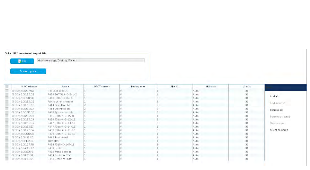
SIP-DECT OM System Manual
346
10.2.1.3 Example
The following figure shows the results of a DECT base station enrolment operation via the OMP DECT
base stations -> Enrolment page.
RFP configuration file/central:
##############################################################################
# instruction section:
##############################################################################
#active
# Activation of DECT:
# {'0' or 'false '= inactive, '1' or 'true' = active}
#cluster
# Cluster, the RFP is referred to:
# {1..256} (RFP OMM) or {1..4096} (PC OMM)
#paging_area
# Ignored by Web import and always set to "0" (PA0)
# Paging area, the RFP is referred to: {'unassigned, '0'..'127'}
#sync_source
# Synchronisation source:
# '0' or 'false '= inactive, '1' or 'true' = active}
#refl_env
# Reflective environment:
# '0' or 'false '= no, '1' or 'true' = yes}
#site
# Site Id: {1..250}
#wlan_profile
# Reference key to an existing WLAN profile
#wlan_antenna
# Antenna settings: {0=diversity, 1, 2}

Appendix
347
#wlan_channel_bg
# WLAN channel: {0..14 (size depends on regulatory domain) }
#wlan_power
# WLAN power = { 6, 12, 25, 50,100 (in percent)}
#wlan_act
# Activation of WLAN:
# '0' or 'false '= inactive, '1' or 'true' = active}
#Note: Web import allows only "0" or "1" for Boolean
##############################################################################
active=1
cluster=100
refl_evc=1
site=1
##############################################################################
data_sequence
##############################################################################
#MAC address;Name;DECT activated;DECT cluster;Paging area;Preferred sync.;
#Reflective env.;Site ID;Building;Floor;Room;WLAN profile;WLAN antenna;
#WLAN channel;WLAN power;WLAN activated
00:30:42:0D:97:1A;R451P31a03054;1;1;0;0;0;1;31;4;;;;;;
00:30:42:0D:95:D8;R439 SWT 31A-0-3-1-2;1;1;0;1;0;1;31;4;;;;;;
00:30:42:0C:BD:7B;R440 P31a-03-07-4;1;1;0;0;0;3;31;4
00:30:42:0D:95:CE;Patchschrank Kueche;1;1;0;0;0;3;31;4
00:30:42:0D:95:CC;R414 OpenMob lab;1;2;0;0;0;3;;
00:30:42:0D:95:CA;R414 OpenMob lab;1;2;0;0;0;3;31;4
00:30:42:0C:BD:DD;R403 System test lab;1;2;0;0;0;3;31;4
00:30:42:0D:95:DB;R451 P31a-4-2-15-8;1;1;0;0;0;1;31;4
00:30:42:0D:95:D9;R439 P31a-4-2-12-13;1;1;0;0;0;3;31;4
00:30:42:0D:95:D6;R447 P31a-4-2-13-18;1;1;0;0;0;3;31;4
00:30:42:0D:95:E7;R447 P31a-4-2-14-13;1;1;0;0;0;1;31;4
00:30:42:0D:22:5A;R433 P31a-4-2-11-10;1;1;0;0;0;3;31;4
00:30:42:0C:BD:68;R433 P31a-4-2-11-13;1;1;0;0;0;1;31;4
00:30:42:0B:92:FC;R443 Test board;1;1;0;0;0;1;31;4
00:30:42:FF:F0:D0;plexiglas;1;1;0;0;0;1;;
00:30:42:0D:27:7D;R434 P31M-0-1-5-19;1;1;0;0;0;3;31;4
00:30:42:0A:C9:62;R439 Decke re.;1;1;0;0;0;1;;
00:30:42:0D:E3:F6;R436 Wand oben ln;1;1;0;0;0;1;;
00:30:42:08:31:5F;R434 Decke ln. Tür;1;1;0;0;0;1
00:30:42:08:31:64;R440 Decke re Fnstr;1;1;0;0;0;1
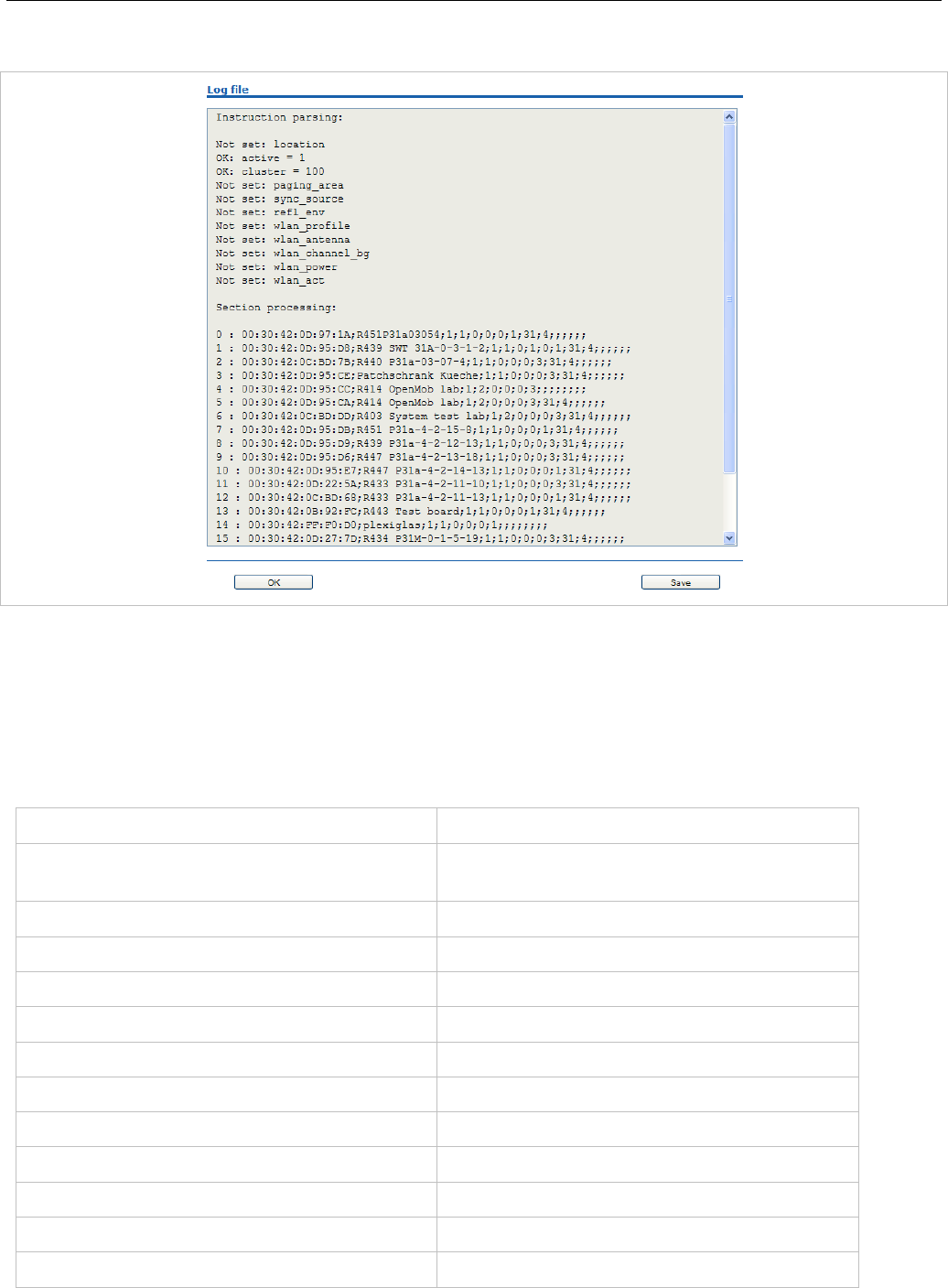
SIP-DECT OM System Manual
348
Parse log about import / instruction processing
10.2.2 RFP CONFIGURATION FILE / LOCAL (OM CONFIGURATOR)
10.2.2.1 Supported Instructions
All instructions are taken as a common value and are applied to all records in the data sequence section
of that file if the corresponding field is empty.
Instruction Explanation
active Local configuration active: {0=inactive(use
DHCP instead), 1=active}
net_mask Net mask
tftp_server IP address of TFTP server
tftp_file Path and name of boot file
omm_1 OMM IP address
omm_2 IP address of backup OMM
gateway Default gateway
dns_server Up to two DNS server IP addresses
dns_domain local DNS domain
syslog_addr IP address of syslog daemon
syslog_port Listen port of syslog daemon
use_vlan VLAN is enabled

Appendix
349
Instruction Explanation
srvlst List of further tftp server
broadcast_addr local broadcast address
vlan_id VLAN Id
preferred_tftp tftp_server is preferred
config_file_server configuration server
10.2.2.2 Data Section Fields
The data section contains the following field order:
1 MAC address of RFP
2 Local configuration active flag
3 IP address of RFP
4 Net mask
5 TFTP server
6 TFTP_FILE
7 OMM IP address
8 IP address of backup OMM
9 Default gateway
10 DNS server
11 DNS domain
12 Syslog daemon IP address
13 Syslog listen port
14 Use VLAN
15 Server list
16 Broadcast address
17 VLAN Id
18 Preferred TFTP server
19 Configuration file server
10.2.2.3 Example
RFP configuration file/local (OM Configurator):
# --------------------#
# instruction section #
# --------------------#
active = 1
net_mask = 255.255.0.0
tftp_server= 172.30.200.92
tftp_file = iprfp2G.tftp

SIP-DECT OM System Manual
350
omm_1 = 172.30.111.188
omm_2 = 172.30.11.181
gateway = 172.30.0.2
dns_server = 172.30.0.4,172.30.0.21
dns_domain = aastra.de
syslog_addr= 172.30.200.92
use_vlan = 1
srvlist = 172.30.0.4,172.30.0.21
broadcast_addr = 172.30.255.255
vlan_id = 4
preferred_tftp = 1
config_file_server = https://server/configfiles/
# --------------#
# data sequence #
# --------------#
# 1. MAC_ADDR ! no instruction supported !
# 2. ACTIVE_FLAG
# 3. RFPADDR ! no instruction supported !
# 4. NET_MASK
# 5. TFTP_SERVER
# 6. TFTP_FILE
# 7. OMM1
# 8. OMM2
# 9. GATEWAY
#10. DNS_SERVER
#11. DNS_DOMAIN
#12. SYSLOG_ADDR
#13. SYSLOG_PORT
#14. USE_VLAN
#15. SRVLIST
#16. BROADCAST_ADDR
#17. VLAN_ID
#18. PREFERRED_TFTP
#19. CONFIG_FILE_SERVER
data_sequence
00-30-42-01-01-01;;172.30.111.1
00-30-42-02-02-02;;172.30.111.2

Appendix
351
Parse log for import / instruction processing
ok: active = 1
ok: net_mask = 255.255.0.0
ok: tftp_server = 172.30.200.92
ok: tftp_file = iprfp2G.tftp
ok: omm_1 = 172.30.111.188
ok: omm_2 = 172.30.11.181
ok: gateway = 172.30.0.2
ok: dns_server = 172.30.0.4,172.30.0.21
ok: dns_domain = mitel.com
ok: syslog_addr = 172.30.200.92
not set: syslog_port
ok: use_vlan = 1
ok: srvlist = 172.30.0.4,172.30.0.21
ok: broadcast_addr = 172.30.255.255
ok: vlan_id = 4
ok: preferred_tftp = 1
ok: config_file_server = https://server/configfiles/
:parsing ok:
processing of section: data_sequence
[…]
create data:
[…]
RFP configuration:
[…]

SIP-DECT OM System Manual
352
10.3 RFP EXPORT FILE FORMAT
General
RFP export files are created by OMM Management Portal in ‘csv’-file format which can be easily viewed
by a spreadsheet application. Export file contains all or a part of the following parameters:
• MAC address
• Location name
• DECT active
• Cluster
• Paging area
• Synchronization source
• Reflective environment
• Site
• Building
• Floor
• Room
• WLAN profile reference
• WLAN antenna
• WLAN Channel_bg
• WLAN power
• WLAN active
Example
Following example RFP export file contains all exportable RFP parameters and is re-importable by OMM
Management Portal.
##################################################
# RFP data export file: '/home/user/example.csv'
# Date: 24.09.10 Time: 15:58:19
##################################################
#
# Exported parameters:
#
# MAC address
# Name
# DECT activated
# DECT cluster
# Paging area
# Preferred sync.
# Reflective env.
# Site ID
# Building
# Floor

Appendix
353
# Room
# WLAN profile
# WLAN antenna
# WLAN channel
# WLAN power
# WLAN activated
#
##################################################
MAC address;Name;DECT activated;DECT cluster;Paging area;Preferred sync.;Reflective
env.;Site ID;Building;Floor;Room;WLAN profile;WLAN antenna;WLAN channel;WLAN power;WLAN
activated
data_sequence
00:30:42:0E:71:41;License RFP 1;
true;1;0;false;true;1;B1;F1;R1;1;0;;100;false
00:30:42:0E:26:F1;License RFP 2;
true;1;0;false;false;1;B1;F2;R1;1;0;;100;false
00:30:42:0E:75:59;License RFP 3;
true;1;0;true;false;1;B1;F2;R2;1;0;;100;false
10.4 COA CONFIGURATION PARAMETERS
In addition to the information provided in section 7.23, the following sections provide an example of a
CoA configuration file, and an overview of all supported parameters.
10.4.1 EXTENDED COA EXAMPLE
UD_ConfigurationName = "omm-test" # name of the configuration file
### message options
UD_MessageMelodyNormal = basic_1
UD_MessageMelodyUrgent = basic_2
UD_MessageMelodyAlarm = basic_3
UD_MessageVolumeNormal = level_1
UD_MessageVolumeUrgent = level_2
UD_MessageVolumeAlarm = level_3
UD_MessageOverwrite = true
### ringer melody options

SIP-DECT OM System Manual
354
UD_RingerMelodyIntern = butterfly
UD_RingerMelodyExtern = barock
UD_RingerMelodyUnknown = ballade
UD_RingerMelodyCallback = fancy
UD_RingerMelodyRecall = comelody
UD_RingerMelodyVip = easy_groove
UD_RingerMelodySpecial = happy_fair
UD_RingerMelodyAlarm = kitafun
UD_RingerMelodyAppointment = latin_dance
### ringer volume options
UD_RingerVolumeIntern = off
UD_RingerVolumeExtern = increasing
UD_RingerVolumeUnknown = level_1
UD_RingerVolumeCallback = level_2
UD_RingerVolumeRecall = level_3
UD_RingerVolumeVip = level_4
UD_RingerVolumeSpecial = level_5
UD_RingerVolumeAlarm = level_6
UD_RingerVolumeAppointment = level_7
### ringer settings
UD_RingMode = repeat
UD_RingBuzz = true
UD_RingVibra = true
UD_RingHeadset = false
### attention tones
UD_ToneKey = inactive active
UD_ToneCnf = active
UD_ToneMnend = active no_speaker
UD_ToneAccu = active vibra
UD_ToneRange = inactive active no_speaker vibra
UD_ToneOutrange = inactive
### audio
UD_AudioNoisedetect = true
UD_AudioLoudenv = false
UD_AudioSpkCharger = handsfree
### Systems/Subscription/<System X>
UD_DialCharset = ABC_123
UD_DialCodeImax = 3

Appendix
355
UD_DialCodeSys = "6"
### display
UD_DispLang=en
UD_DispFont=large
UD_DispColor=black
### illumination
UD_LightDim = 2h
UD_LightDisp = 2m
UD_LightKey = 45s
UD_LightKeyoptIncom = true
UD_LightKeyoptAlarm = false
UD_LightKeyoptCharge = false
UD_LightCharge = 60s
UD_LightCall = 30s
UD_LightMsgMsg = 10s
UD_LightMsgInf = 20s
UD_LightMsgJob = 30s
UD_LightMsgSos = 60s
### led indications
UD_LedAlive = true
UD_LedIncom = true
UD_LedRange = false
UD_LedCharge = true
UD_LedInfo = false
UD_LedSpk = true
UD_LedAutoans = false
UD_LedAppoint = false
UD_LedAlarm = false
### list access
UD_ListmodeRedial = pbx
UD_ListmodeCaller = pbx
UD_ListmodeFilter = block_list
### device options
UD_ModeSilentcharge = true
UD_ModeChargeranswr = false
UD_ModeAutoanswr = true
UD_ModeAutoquickhook = false
UD_ModeKey = oem

SIP-DECT OM System Manual
356
### phone lock
UD_LockKeyAuto = true
UD_LockKeyTime = 30s
UD_LockKeyPin = true
UD_LockPin = "1234"
UD_LockAdmin = "4711"
### SOS call
UD_SosNumber = "4711"
UD_SosMelody = weekend
UD_SosVolume = increasing
UD_SosHandsfree = true
### alarm sensor
UD_SosMdNumber = "0815"
UD_SosMdAutoanswr = true
UD_SosMdModePre = false
UD_SosMdModeDown = true
UD_SosMdModeNomove = true
UD_SosMdModeEsc = false
UD_SosMdModeRep = false
UD_SosMdSenseAngle = flat
UD_SosMdSenseMove = high
UD_SosMdSenseEsc = medium
UD_SosMdNomoDown = conversation system_menu local_menu
UD_SosMdNomoNomove = conversation
UD_SosMdNomoEsc = idle conversation system_menu local_menu
UD_SosMdDelayDown = 20s
UD_SosMdDelayNomove = 30s
UD_SosMdDelayEsc = 45s
UD_SosMdTimePre = 30s
UD_SosMdTimeRep = 60s
UD_SosMdTone = true
UD_SosMdVibra = false
### function/feature access
UD_FunctionMenuHide=active_features true
UD_FunctionMenuHide=prog_x TRUE
UD_FunctionLocked=time_x true
UD_FunctionUserProtected=system_x true
UD_FunctionUserProtected=dir_x true
UD_FunctionAdminProtected=system_x true

Appendix
357
UD_FunctionGrayed=system_x true
### assignment of keys
UD_KeyAssignmentIdle=side1 caller
UD_KeyAssignmentIdle=ok MenuInfNew
UD_KeyAssignmentIdle=long.ok inf
UD_KeyAssignmentIdle=esc gappp_directory
UD_KeyAssignmentIdle=long.esc directories
UD_KeyAssignmentActive=esc nop
UD_KeyAssignmentIdle=side1 sos_loc
UD_KeyAssignmentIdle=side2 shock
UD_KeyAssignmentIdle=side3 sensor_menu
10.4.2 SUPPORTED COA PARAMETERS
The following keys and values are supported in the CoA configuration files.
UD_ConfigurationName= // <string>
// message melody options
UD_MessageMelodyNormal= // VAL_MELODY_xxx
UD_MessageMelodyUrgent= // VAL_MELODY_xxx
UD_MessageMelodyAlarm= // VAL_MELODY_xxx
// message volume options
UD_MessageVolumeNormal= // VAL_VOLUME_xxx
UD_MessageVolumeUrgent= // VAL_VOLUME_xxx
UD_MessageVolumeAlarm= // VAL_VOLUME_xxx
// message overwrite
UD_MessageOverwrite= // true/false
// ringer melody options
UD_RingerMelodyIntern= // VAL_MELODY_xxx
UD_RingerMelodyExtern= // VAL_MELODY_xxx
UD_RingerMelodyUnknown= // VAL_MELODY_xxx
UD_RingerMelodyCallback= // VAL_MELODY_xxx
UD_RingerMelodyRecall= // VAL_MELODY_xxx
UD_RingerMelodyVip= // VAL_MELODY_xxx
UD_RingerMelodySpecial= // VAL_MELODY_xxx
UD_RingerMelodyAlarm= // VAL_MELODY_xxx
UD_RingerMelodyAppointment= // VAL_MELODY_xxx
// melodies
"weekend" // Weekend
"butterfly" // Butterfly
"barock" // Barock
"ballade" // Ballade
"fancy" // Fancy
"comelody" // Comelody
"easy_groove" // Easy groove
"happy_fair" // Happy fair

SIP-DECT OM System Manual
358
"kitafun" // Kitafun
"latin_dance" // Latin dance
"little_asia" // Little asia
"mango_selassi" // Mango selassi
"parka" // Parka
"remember" // Remember
"rocky_lane" // Rocky lane
"ringing_1" // Ringing 1
"ringing_2" // Ringing 2
"ringing_3" // Ringing 3
"ringing_4" // Ringing 4
"ringing_5" // Ringing 5
"ringing_6" // Ringing 6
"ringing_7" // Ringing 7
"ring_vintage" // Ring vintage
"vibes" // Vibes
"attack" // Attack
"doorbell" // Doorbell
"boogie" // Boogie
"polka" // Polka
"classical_1" // Classical 1
"classical_2" // Classical 2
"classical_3" // Classical 3
"classical_4" // Classical 4
"alla_turca" // Alla turca
"entertainer" // Entertainer
"jollygood" // Jollygood
"in_the_saints" // In the saints
"drunken_sailor" // Drunken sailor
"mary_had" // Mary had
"shell_be_walking" // Shell be walking
"pippi_longstocking" // Pippi longstocking
"policehorn" // Policehorn
"synthesizer" // Synthesizer
"after_work" // After work
"beep" // Beep
"basic_1" // Basic 1
"basic_2" // Basic 2
"basic_3" // Basic 3
"basic_4" // Basic 4
"basic_5" // Basic 5
"basic_6" // Basic 6
"basic_7" // Basic 7
"basic_8" // Basic 8
"alarm_1" // Alarm 1
"alarm_2" // Alarm 2
"alarm_3" // Alarm 3
"alarm_4" // Alarm 4
"alarm_5" // Alarm 5
"alarm_6" // Alarm 6
"alarm_7" // Alarm 7
"6700_one" // 6700 One
"6700_two" // 6700 Two
"6700_three" // 6700 Three
"6700_four" // 6700 Four
"6700_five" // 6700 Five
"1_attention_tone" // 1 Attention tone
"2_attention_tones" // 2 Attention tones
"3_attention_tones" // 3 Attention tones
"4_attention_tones" // 4 Attention tones
"5_attention_tones" // 5 Attention tones

Appendix
359
"6_attention_tones" // 6 Attention tones
"7_attention_tones" // 7 Attention tones
"8_attention_tones" // 8 Attention tones
"9_attention_tones" // 9 Attention tones
"10_attention_tones" // 10 Attention tones
// ringer volume options
UD_RingerVolumeIntern= // VAL_VOLUME_xxx
UD_RingerVolumeExtern= // VAL_VOLUME_xxx
UD_RingerVolumeUnknown= // VAL_VOLUME_xxx
UD_RingerVolumeCallback= // VAL_VOLUME_xxx
UD_RingerVolumeRecall= // VAL_VOLUME_xxx
UD_RingerVolumeVip= // VAL_VOLUME_xxx
UD_RingerVolumeSpecial= // VAL_VOLUME_xxx
UD_RingerVolumeAlarm= // VAL_VOLUME_xxx
UD_RingerVolumeAppointment= // VAL_VOLUME_xxx
// volumes
"off" // off
"increasing" // increasing
"level_1" // Level-1
"level_2" // Level-2
"level_3" // Level-3
"level_4" // Level-4
"level_5" // Level-5
"level_6" // Level-6
"level_7" // Level-7
// ringer settings
UD_RingMode= // VAL_RING_MODE_xxx
UD_RingBuzz= // true/false
UD_RingVibra= // true/false
UD_RingHeadset= // true/false
"repeat" // repeat
"once" // once
// attention tones
UD_ToneKey= // VAL_TONE_xxx (up to 3 values)
UD_ToneCnf= // VAL_TONE_xxx (up to 3 values)
UD_ToneMnend= // VAL_TONE_xxx (up to 3 values)
UD_ToneAccu= // VAL_TONE_xxx (up to 3 values)
UD_ToneRange= // VAL_TONE_xxx (up to 3 values)
UD_ToneOutrange= // VAL_TONE_xxx (up to 3 values)
"inactive" // inactive
"active" // active
"no_speaker" // without Loudspeaker
"vibra" // Vibration
// audio
UD_AudioNoisedetect= // true/false
UD_AudioLoudenv= // true/false
UD_AudioSpkCharger= // VAL_AUDIO_SPK_CHARGER_xxx
"release" // Release
"handsfree" // Handsfree
// Systems/Subscription/<System X>
UD_DialCharset= // VAL_DIAL_ABC_xxx
UD_DialCodeImax= // VAL_DIAL_CODE_IMAX_xxx

SIP-DECT OM System Manual
360
UD_DialCodeSys= // <digit-string>
"123_" // 123...
"ABC_123" // ABC...123
"123_ABC_äöü" // 123...ABC...äöü
"ABC_äöü_123" // ABC...äöü...123
"123_ABC" // 123...ABC
"automatic" // automatic
"1" // 1
"2" // 2
"3" // 3
"4" // 4
"5" // 5
"6" // 6
"7" // 7
"8" // 8
// display
UD_DispLang= // VAL_DISP_LANG_xxx
UD_DispFont= // VAL_DISP_FONT_xxx
UD_DispColor= // VAL_DISP_COLOR_xxx
"default" // default
"de" // D - Deutsch
"en" // GB - English
"fr" // FR - Français
"es" // ES - Español
"it" // I - Italiano
"nl" // NL - Nederlands
"sv" // S - Svenska
"da" // DK - Dansk
"pt" // P - Português
"no" // N - Norsk
"cs" // Cz - Cesky
"sk" // SK - Sloven?ina - Slovensky
"fi" // Su - Suomi
"hu" // H - Magyar - Hungarian
"ru" // RU - ??????? - Russian
"tr" // TURK - Türkçe
"pl" // PL - Polski
"et" // EST - Esti
"small" // Small
"normal" // Normal
"large" // Large
"gray" // Gray
"black" // Black
"business" // Business
"future" // Future
"plain" // Plain
"sweet" // Sweet
// illumination
UD_LightDim= // VAL_LIGHT_DIM_xxx
UD_LightDisp= // VAL_LIGHT_DISP_xxx
UD_LightKey= // VAL_LIGHT_KEY_xxx
UD_LightKeyoptIncom= // true/false
UD_LightKeyoptAlarm= // true/false
UD_LightKeyoptCharge= // true/false

Appendix
361
UD_LightCharge= // VAL_LIGHT_CHARGE_xxx
UD_LightCall= // VAL_LIGHT_CALL_xxx
UD_LightMsgMsg= // VAL_LIGHT_MSG_MSG_xxx
UD_LightMsgInf= // VAL_LIGHT_MSG_INF_xxx
UD_LightMsgJob= // VAL_LIGHT_MSG_JOB_xxx
UD_LightMsgSos= // VAL_LIGHT_MSG_SOS_xxx
"off" // off
"1m" // 1 min
"10m" // 10 min
"1h" // 60 min
"2h" // 120 min
"4h" // 240 min
"10h" // 600 min
"on" // on
"10s" // 10 sec
"20s" // 20 sec
"30s" // 30 sec
"45s" // 45 sec
"60s" // 60 sec
"2m" // 120 sec
"4m" // 240 sec
"off" // off
"1s" // 1 sec
"3s" // 3 sec
"5s" // 5 sec
"10s" // 10 sec
"20s" // 20 sec
"30s" // 30 sec
"45s" // 45 sec
"60s" // 60 sec
"2m" // 120 sec
"4m" // 240 sec
"off" // off
"1s" // 1 sec
"3s" // 3 sec
"5s" // 5 sec
"10s" // 10 sec
"20s" // 20 sec
"30s" // 30 sec
"45s" // 45 sec
"60s" // 60 sec
"2m" // 120 sec
"4m" // 240 sec
"off" // off
"1s" // 1 sec
"3s" // 3 sec
"5s" // 5 sec
"10s" // 10 sec
"20s" // 20 sec
"30s" // 30 sec
"45s" // 45 sec
"60s" // 60 sec
"2m" // 120 sec
"3m" // 180 sec
"4m" // 240 sec
"on" // on

SIP-DECT OM System Manual
362
"nochange" // No change
"dimmed" // Light dimmed
"5s" // 5 sec
"10s" // 10 sec
"20s" // 20 sec
"30s" // 30 sec
"45s" // 45 sec
"60s" // 60 sec
"2m" // 120 sec
"4m" // 240 sec
"nochange" // No change
"dimmed" // Light dimmed
"5s" // 5 sec
"10s" // 10 sec
"20s" // 20 sec
"30s" // 30 sec
"45s" // 45 sec
"60s" // 60 sec
"2m" // 120 sec
"4m" // 240 sec
"nochange" // No change
"dimmed" // Light dimmed
"5s" // 5 sec
"10s" // 10 sec
"20s" // 20 sec
"30s" // 30 sec
"45s" // 45 sec
"60s" // 60 sec
"2m" // 120 sec
"4m" // 240 sec
"dimmed" // Light dimmed
"30s" // 30 sec
"60s" // 60 sec
"2m" // 120 sec
"3m" // 180 sec
"4m" // 240 sec
"5m" // 300 sec
// led indications
UD_LedAlive= // true/false
UD_LedIncom= // true/false
UD_LedRange= // true/false
UD_LedCharge= // true/false
UD_LedInfo= // true/false
UD_LedSpk= // true/false
UD_LedAutoans= // true/false
UD_LedAppoint= // true/false
UD_LedAlarm= // true/false
// list access
UD_ListmodeRedial= // VAL_LISTMODE_REDIAL_xxx
UD_ListmodeCaller= // VAL_LISTMODE_CALLER_xxx
UD_ListmodeFilter= // VAL_LISTMODE_FILTER_xxx
"local" // local
"automatic" // automatic
"pbx" // PBX

Appendix
363
"local" // local
"automatic" // automatic
"pbx" // PBX
"accept_list" // Accept list
"block_list" // Block list
"filter_off" // Filter off
// device options
UD_ModeSilentcharge= // true/false
UD_ModeChargeranswr= // true/false
UD_ModeAutoanswr= // true/false
UD_ModeAutoquickhook= // true/false
UD_ModeKey= // VAL_MODE_KEY_xxx
"emo" // Esc >>> Ok
"oem" // Ok Esc >>>
"eom" // Esc Ok >>>
"meo" // >>> Esc Ok
"EMO" // Esc Menu Ok
"OEM" // Ok Esc Menu
"EOM" // Esc Ok Menu
"MEO" // Menu Esc Ok
// phone lock
UD_LockKeyAuto= // true/false
UD_LockKeyTime= // VAL_LOCK_KEY_T_xxx
UD_LockKeyPin= // true/false
UD_LockPin= // <digit-string>
UD_LockAdmin= // <digit-string>
"5s" // 5 sec
"10s" // 10 sec
"20s" // 20 sec
"30s" // 30 sec
"40s" // 40 sec
"50s" // 50 sec
"60s" // 60 sec
"90s" // 90 sec
"120s" // 120 sec
// SOS call
UD_SosNumber= // <digit-string>
UD_SosMelody= // VAL_MELODY_xxx
UD_SosVolume= // VAL_VOLUME_xxx
UD_SosHandsfree= // true/false
// alarm sensor
UD_SosMdNumber= // <digit-string>
UD_SosMdAutoanswr= // true/false
UD_SosMdModePre= // true/false
UD_SosMdModeDown= // true/false
UD_SosMdModeNomove= // true/false
UD_SosMdModeEsc= // true/false
UD_SosMdModeRep= // true/false
UD_SosMdSenseAngle= // VAL_SOSMD_SENSE_ANGLE_xxx
UD_SosMdSenseMove= // VAL_SOSMD_SENSE_MOVE_xxx
UD_SosMdSenseEsc= // VAL_SOSMD_SENSE_ESC_xxx
UD_SosMdNomoDown= // VAL_SOSMD_NOMO_xxx (up to 4 values)
UD_SosMdNomoNomove= // VAL_SOSMD_NOMO_xxx (up to 4 values)

SIP-DECT OM System Manual
364
UD_SosMdNomoEsc= // VAL_SOSMD_NOMO_xxx (up to 4 values)
UD_SosMdDelayDown= // VAL_SOSMD_DELAY_DOWN_xxx
UD_SosMdDelayNomove= // VAL_SOSMD_DELAY_NOMOVE_xxx
UD_SosMdDelayEsc= // VAL_SOSMD_DELAY_ESC_xxx
UD_SosMdTimePre= // VAL_SOSMD_T_PRE_xxx
UD_SosMdTimeRep= // VAL_SOSMD_T_REP_xxx
UD_SosMdTone= // true/false
UD_SosMdVibra= // true/false
"steep" // Steep
"medium" // Medium
"flat" // Flat
"low" // Low
"medium" // Medium
"high" // High
"low" // Low
"medium" // Medium
"high" // High
"idle" // in idle
"conversation" // during conversation
"local_menu" // in local menu
"system_menu" // in system menu
"1s" // 1 sec
"2s" // 2 sec
"5s" // 5 sec
"10s" // 10 sec
"20s" // 20 sec
"30s" // 30 sec
"45s" // 45 sec
"60s" // 60 sec
"75s" // 75 sec
"10s" // 10 sec
"20s" // 20 sec
"30s" // 30 sec
"45s" // 45 sec
"60s" // 60 sec
"75s" // 75 sec
"1s" // 1 sec
"2s" // 2 sec
"5s" // 5 sec
"10s" // 10 sec
"20s" // 20 sec
"30s" // 30 sec
"45s" // 45 sec
"60s" // 60 sec
"75s" // 75 sec
"10s" // 10 sec
"20s" // 20 sec
"30s" // 30 sec
"45s" // 45 sec
"60s" // 60 sec
"75s" // 75 sec
"5s" // 5 sec

Appendix
365
"10s" // 10 sec
"20s" // 20 sec
"30s" // 30 sec
"45s" // 45 sec
"60s" // 60 sec
"75s" // 75 sec
"120s" // 120 sec
"240s" // 240 sec
// function/feature access
UD_FunctionMenuHide= // VAL_FUNCTION_xxx and true/false
UD_FunctionLocked= // VAL_FUNCTION_xxx and true/false
UD_FunctionGrayed= // VAL_FUNCTION_xxx and true/false
UD_FunctionUserProtected= // VAL_FUNCTION_xxx and true/false
UD_FunctionAdminProtected= // VAL_FUNCTION_xxx and true/false
// functions/features available on device
"pbx_unpark" // <<< Unpark call(*)
"pbx_park" // <<< Pickup/Park(*)
"gappp_pickup" // <<< Pickup call(*)
"pbx_take" // <<< Take call(*)
"gappp_call_forward" // <<< Call diversion(*)
"pbx_call_routing" // <<< Call routing(*)
"gappp_pickup_select" // Pickup select
"gappp_announcement" // Announcement
"gappp_intercom" // Intercom
"gappp_vip_call" // VIP call
"inf" // >>> Info (menu item only)
"caller" // Caller list
"redial" // Redial list
"box_x" // >>> Voice box
"box_set_x" // Voice box settings
"voice_box_menu" // Settings/Voice mail(*)
"active_features" // >>> Active features
"msg_x" // >>> Text message / Jobs / Mails(*)
"omm_def_msg" // Pre-defined messages
"msg_opt_x" // Message options
"mel_msg_x" // Melodies
"mel_msg" // Normal message
"mel_msgurg" // Urgent message
"mel_msgsos" // Alarm message
"vol_msg_x" // Volume
"vol_msg" // Normal message
"vol_msgurg" // Urgent message
"vol_msgsos" // Alarm message
"msg_pop" // Popup
"msg_ovwr" // Overwrite
"msg_del" // Delete/Delete all
"directory_x" // >>> Directories
"vip" // VIP list
"vip_x" // Edit/Add VIP list entry
"dir_x" // Personal directory
"book_x" // Edit/Add personal directory entry
"quick_x" // Quick call
"add_to" // Add to...(VIP/Filter/Personal/Central directory)
"pbx_directory" // Central directory(*)
"time_x" // >>> Time functions
"alarm_x" // Alarm clock 1...3
"appointment_x" // Appointment 1...3
"tea_timer" // Timer
"audio_x" // >>> Audio

SIP-DECT OM System Manual
366
"volume_menu" // Volume settings
"tone_menu" // Attention tones
"tone_key" // Key click
"tone_cnf" // Confirm tones
"tone_end" // End of menu
"tone_bat" // Battery warning
"tone_charger" // Charger beep
"tone_cov" // Coverage warning
"tone_range" // Out of range
"tone_wait" // Call waiting
"tone_sensor" // Pre alarm (63x only)
"load_environment" // Loud environment
"audio_hd" // Audio quality (only 650)
"ring_x" // >>> Ringing
"ring_mel_x" // Ringer melodies
"mel_int" // Internal call
"mel_ext" // External call
"mel_unk" // Unknown number
"mel_nym" // Anonymous
"mel_ccbs" // Callback
"mel_recall" // Recall
"mel_vip" // VIP call
"mel_special" // Special call
"mel_sos" // Emergency call
"mel_alarm" // Alarm
"mel_app" // Appointment
"ring_volume" // Ringer volume
"vol_int" // Internal call
"vol_ext" // External call
"vol_unk" // Unknown number
"vol_nym" // Anonymous
"vol_ccbs" // Callback
"vol_recall" // Recall
"vol_vip" // VIP call
"vol_special" // Special call
"vol_sos" // Emergency call
"vol_alarm" // Alarm
"vol_app" // Appointment
"ring_type_x" // Ringer type
"play_once" // Play melody once on/off
"silent_charging" // Silent charging
"noise_detection" // Noise detection on/off
"ring_device_x" // Ringer device
"ring_off" // Ringer/Buzzer on/off
"ring_hs" // Corded headset-ring on/off
"ring_vibra" // Vibrator-ring on/off
"datamanagment" // >>> Data management / SD Card
"filter_xx" // >>> Call filter
"filter_x" // Edit call filter
"system_x" // >>> System/Subscription
"start_enrol" // <New system>
"subs_auto" // Auto search
"subs_sel" // Select subscription
"subs_stop" // Stop searching
"subs_opt" // >Edit subscription
"no_plan" // Number plan
"ehs_x" // >>> Enhanced security
"bt_x" // >>> Bluetooth (only 62x/63x/65x)
"bt_edit_x" // >Edit Bluetooth
"set_xx" // >>> User settings
"prog_x" // Key programming

Appendix
367
"disp_x" // Display settings
"language" // Language
"font" // Font settings
"color" // Color schemes
"scheme" // Menu structure
"pic_x" // Idle picture
"illu_x" // Illumination/Light
"disp_dim" // Display dimming
"disp_light" // Display
"disp_key" // Keyboard
"disp_charger" // Charger
"disp_call" // Conversation
"disp_inf" // Info message
"disp_msg" // Text message
"disp_job1" // Job
"disp_sos" // SOS alarm
"disp_led" // LED indications
"led_alife" // Life indication
"led_incom" // Incoming call
"led_range" // Out of range
"led_charge" // Charge indication
"led_inf" // Infos
"led_spk" // Handsfree
"led_app" // Appointment
"led_alarm" // Alarm
"list_settings" // List access
"device_opt" // Device options
"security_x" // >>> Security
"lock_x" // >>> Lock
"keylock" // Key lock
"pinlock" // Phone lock
"change_pin" // Change PIN
"sos_x" // >>> SOS call
"tms_x" // >>> Alarm sensor (63x only)
"set_pre_alarm" // Pre alarm
"set_mandown" // Mandown
"set_no_move" // No movement alarm
"set_shock" // Shock alarm
"set_rep_alarm" // Repeate alarm
"tms_opt_x" // >Sensor options
"rst_x" // >>> Reset to default
"off_menu" // >>> Off menu
"off" // Power off
"menu" // Menu
"ring_toggle" // Ringer/Buzzer on/off
"profile_x" // >>> Profiles
"prof_no" // <No profile>
"prof_norm" // Normal
"prof_hs" // Headset
"prof_meet" // Meeting
"prof_loud" // Loud
"prof_my" // <Profile 05>
"prof_ed_x" // Edit profiles
"prof_ed_norm" // Edit Normal
"prof_ed_hs" // Edit Headset
"prof_ed_meet" // Edit Meeting
"prof_ed_loud" // Edit Loud
"usb_mode" // USB mode
"doa_master" // DOA master
"f_x" // <<< XML Applications / Functions 01..10(*)
"pbx_fkeys" // <<< List of applications / functions(*)

SIP-DECT OM System Manual
368
"f_1" // App/F01(*)
"f_2" // App/F02(*)
"f_3" // App/F03(*)
"f_4" // App/F04(*)
"f_5" // App/F05(*)
"f_6" // App/F06(*)
"f_7" // App/F07(*)
"f_8" // App/F08(*)
"f_9" // App/F09(*)
"f_10" // App/F10(*)
"vlstx" // Variable lists
"vlst1" // Variable list 1
"vlst1_1" // List 1 item 1
"vlst1_2" // List 1 item 2
"vlst1_3" // List 1 item 3
"vlst1_4" // List 1 item 4
"vlst1_5" // List 1 item 5
"vlst1_6" // List 1 item 6
"vlst1_7" // List 1 item 7
"vlst1_8" // List 1 item 8
"vlst1_9" // List 1 item 9
"vlst1_10" // List 1 item 10
"vlst2" // Variable list 2
"vlst2_1" // List 2 item 1
"vlst2_2" // List 2 item 2
"vlst2_3" // List 2 item 3
"vlst2_4" // List 2 item 4
"vlst2_5" // List 2 item 5
"vlst2_6" // List 2 item 6
"vlst2_7" // List 2 item 7
"vlst2_8" // List 2 item 8
"vlst2_9" // List 2 item 9
"vlst2_10" // List 2 item 10
"menu_x" // All menus
"opt" // All dial/call options
// assignment of keys
UD_KeyAssignmentIdle= // VAL_KEY_xxx and VAL_FKT_IDLE_xxx
UD_KeyAssignmentDial= // VAL_KEY_xxx and VAL_FKT_DIAL_xxx
UD_KeyAssignmentAlert= // VAL_KEY_xxx and VAL_FKT_ALERT_xxx
UD_KeyAssignmentActive= // VAL_KEY_xxx and VAL_FKT_ACTIVE_xxx
UD_KeyAssignmentIdleMaster= // VAL_KEY_xxx and VAL_FKT_IDLE_xxx
UD_KeyAssignmentDialMaster= // VAL_KEY_xxx and VAL_FKT_DIAL_xxx
UD_KeyAssignmentAlertMaster= // VAL_KEY_xxx and VAL_FKT_ALERT_xxx
UD_KeyAssignmentActiveMaster= // VAL_KEY_xxx and VAL_FKT_ACTIVE_xxx
// keys available on device
"sos" // SOS-key (sos)
"side1" // Side key up (side1)
"side2" // Side key middle (side2)
"side3" // Side key down (side3)
"vip" // Hotkey (vip)
"ok" // Softkey left (ok)
"esc" // Softkey middle (esc)
"opt" // Softkey right (opt)
"left" // Navi. left (left)
"right" // Navi. right (right)
"up" // Navi. up (up)
"down" // Navi. down (down)
"green" // Hook off (green)

Appendix
369
"red" // Hook on (red)
"long.sos" // SOS-key long (long.sos)
"long.side1" // Side key up long (long.side1)
"long.side2" // Side key middle long (long.side2)
"long.side3" // Side key down long (long.side3)
"long.vip" // Hotkey long (long.vip)
"long.ok" // Softkey left long (long.ok)
"long.esc" // Softkey middle long (long.esc)
"long.opt" // Softkey right long (long.opt)
"long.left" // Navi. left long (long.left)
"long.right" // Navi. right long (long.right)
"long.green" // Hook off long (long.green)
"long.red" // Hook on long (long.red)
"long.d0" // Key 0 long (long.d0)
"long.d1" // Key 1 long (long.d1)
"long.d2" // Key 2 long (long.d2)
"long.d3" // Key 3 long (long.d3)
"long.d4" // Key 4 long (long.d4)
"long.d5" // Key 5 long (long.d5)
"long.d6" // Key 6 long (long.d6)
"long.d7" // Key 7 long (long.d7)
"long.d8" // Key 8 long (long.d8)
"long.d9" // Key 9 long (long.d9)
"long.star" // Star key long (long.star)
"long.hash" // Hash key long (long.hash)
"d0" // Key 0 (d0)
"d1" // Key 1 (d1)
"d2" // Key 2 (d2)
"d3" // Key 3 (d3)
"d4" // Key 4 (d4)
"d5" // Key 5 (d5)
"d6" // Key 6 (d6)
"d7" // Key 7 (d7)
"d8" // Key 8 (d8)
"d9" // Key 9 (d9)
"star" // Star key (star)
"hash" // Hash key (hash)
"del" // C-key (del)
"spk" // Handsfree (spk)
"long.del" // C-key long (long.del)
"long.spk" // Handsfree long (long.spk)
// functions available in IDLE state
"nop" // <no function>
"prog" // <key programming>
"menu" // >>>Menu
"dyn_pbx_option" // >>>System options / main menu
"pbx_server_menu" // >>>Server menu
"alarm_time" // Time/Alarms
"alarm" // Alarm clock
"appointment" // Appointment
"tea_timer" // Timer
"directories" // Directories (Personal/Central/VIP-list)
"get_name" // Get name from personal directory
"book" // Personal directory
"gappp_directory" // Central directory (obsolete)
"pbx_directory" // Central directory(*)
"vip" // VIP list
"quick0" // Quick call list
"sos_menu" // SOS call: with confirmation
"sos" // SOS call

SIP-DECT OM System Manual
370
"sos_loc" // Localisation alarm
"shock" // Shock detection
"alarm_call" // Alarm call
"sensor_menu" // Alarm sensor
"navi" // Navigation key
"inf" // (i) Info menu
"MenuInfNew" // (i) New infos
"voice_box" // Voice box
"caller" // Caller list
"redial" // Redial list
"omm_jobs" // Job list
"BestMsg" // Text messages
"omm_inbox" // Inbox/Text messages
"omm_outbox" // Outbox/Text messages
"omm_def_msg" // Pre-defined messages
"txt_send" // Send new text message
"active_features" // Active Handset features
"feature_access_code" // Feature access codes(*)
"pbx_unpark" // Unpark call(*)
"gappp_pickup" // Pickup call(*)
"pbx_take" // Take call(*)
"locating_editor" // Locating(*)
"pbx_presence" // Presence(*)
"pbx_dnd" // Call protection(*)
"gappp_call_forward" // Call diversion(*)
"pbx_call_routing" // Call routing(*)
"profile" // Profile
"datamanagment" // Data managment
"keylock" // Key lock
"pinlock" // Pin/Phone lock
"light_toggle" // Light on/off
"bt" // Bluetooth settings
"bt_state" // BT status (on/off)
"ring_off" // Ringer on/off
"vol_ok" // Volume settings
"audio_hd" // HiQ audio on/off
"off" // Power off
"predial" // Please dial editor
"version" // Version info
"filter_menu" // Call filter
"filter_state" // Call filter state
"pbx_fkeys" // XML Applications
"f_1" // App 1
"f_2" // App 2
"f_3" // App 3
"f_4" // App 4
"f_5" // App 5
"f_6" // App 6
"f_7" // App 7
"f_8" // App 8
"f_9" // App 9
"f_10" // App 10
"vlstx" // Variable lists
"vlst1" // Variable list 1
"vlst1_1" // List 1 item 1
"vlst1_2" // List 1 item 2
"vlst1_3" // List 1 item 3
"vlst1_4" // List 1 item 4
"vlst1_5" // List 1 item 5
"vlst1_6" // List 1 item 6
"vlst1_7" // List 1 item 7

Appendix
371
"vlst1_8" // List 1 item 8
"vlst1_9" // List 1 item 9
"vlst1_10" // List 1 item 10
"vlst2" // Variable list 2
"vlst2_1" // List 2 item 1
"vlst2_2" // List 2 item 2
"vlst2_3" // List 2 item 3
"vlst2_4" // List 2 item 4
"vlst2_5" // List 2 item 5
"vlst2_6" // List 2 item 6
"vlst2_7" // List 2 item 7
"vlst2_8" // List 2 item 8
"vlst2_9" // List 2 item 9
"vlst2_10" // List 2 item 10
// functions available in DIAL state
"nop" // <no function>
"sk_dyn1" // <dynamic soft-key>
"caller" // Caller list
"redial" // Redial list
"get_name" // Get name from personal directory
"book_req" // Personal directory
"gappp_directory" // Central directory (obsolete)
"pbx_directory" // Central directory(*)
"vip" // VIP list
"add_to" // Add to... (VIP-, Filter-list, Personal directory)
"gappp_pickup_select" // Pickup select
"gappp_vip_call" // VIP call
"gappp_announcement" // Announcement
"gappp_intercom" // Intercom
"vlstx" // Variable lists
"vlst1" // Variable list 1
"vlst1_1" // List 1 item 1
"vlst1_2" // List 1 item 2
"vlst1_3" // List 1 item 3
"vlst1_4" // List 1 item 4
"vlst1_5" // List 1 item 5
"vlst1_6" // List 1 item 6
"vlst1_7" // List 1 item 7
"vlst1_8" // List 1 item 8
"vlst1_9" // List 1 item 9
"vlst1_10" // List 1 item 10
"vlst2" // Variable list 2
"vlst2_1" // List 2 item 1
"vlst2_2" // List 2 item 2
"vlst2_3" // List 2 item 3
"vlst2_4" // List 2 item 4
"vlst2_5" // List 2 item 5
"vlst2_6" // List 2 item 6
"vlst2_7" // List 2 item 7
"vlst2_8" // List 2 item 8
"vlst2_9" // List 2 item 9
"vlst2_10" // List 2 item 10
// functions available in ALERTING state
"nop" // <no function>
"na" // <not available>
"sk_dyn1" // <dynamic soft-key>
"opt" // >>>Call options
"acc" // Accept call / Hook off
"rej" // Reject call / Hook on

SIP-DECT OM System Manual
372
"ring_off" // Ringing off
"add_to" // Add to... (VIP-, Filter-list, Personal directory)
"opt_ccbs" // Callback CCBS
"opt_ccnr" // Callback CCNR
"opt_mcid" // Intercept MCID
"opt_pickup" // Pickup call
"opt_pickup_select" // Pickup select
"opt_park" // Park call/Unpark call
"opt_take" // Take call
"vlstx" // Variable lists
"vlst1" // Variable list 1
"vlst1_1" // List 1 item 1
"vlst1_2" // List 1 item 2
"vlst1_3" // List 1 item 3
"vlst1_4" // List 1 item 4
"vlst1_5" // List 1 item 5
"vlst1_6" // List 1 item 6
"vlst1_7" // List 1 item 7
"vlst1_8" // List 1 item 8
"vlst1_9" // List 1 item 9
"vlst1_10" // List 1 item 10
"vlst2" // Variable list 2
"vlst2_1" // List 2 item 1
"vlst2_2" // List 2 item 2
"vlst2_3" // List 2 item 3
"vlst2_4" // List 2 item 4
"vlst2_5" // List 2 item 5
"vlst2_6" // List 2 item 6
"vlst2_7" // List 2 item 7
"vlst2_8" // List 2 item 8
"vlst2_9" // List 2 item 9
"vlst2_10" // List 2 item 10
// functions available in ACTIVE state
"nop" // <no function>
"sk_dyn1" // <dynamic soft-key>
"opt" // >>>Call options
"pbx_server_menu" // >>>Server menu(*)
"feature_access_code" // >>>Feature access codes(*)
"dial_r" // (R) Register recall
"opt_ect" // Transfer call
"opt_brokering" // Brokering
"opt_hold" // Hold call
"opt_3pty" // Conference start/stopp
"opt_park" // Park call/Unpark call
"rel" // Release call / Hook on
"add_to" // Add to... (VIP-, Filter-list, Personal directory)
"book" // Personal directory
"gappp_directory" // Central directory (obsolete)
"pbx_directory" // Central directory(*)
"vip" // VIP list
"quick0" // Quick call list
"filter" // Call filter list
"caller" // Caller list
"redial" // Redial list
"txt_send" // Send new text message
"vol_ok" // Volume settings
"vol_up" // Volume +
"vol_down" // Volume -
"mute" // Microphone on/off
"audio_hd" // HiQ audio on/off

Appendix
373
"bt_toggle" // Transfer BT <-> Handset
"opt_mcid" // Intercept MCID
"opt_pickup" // Pickup
"opt_pickup_select" // Pickup select
"opt_take" // Take call
"vlstx" // Variable lists
"vlst1" // Variable list 1
"vlst1_1" // List 1 item 1
"vlst1_2" // List 1 item 2
"vlst1_3" // List 1 item 3
"vlst1_4" // List 1 item 4
"vlst1_5" // List 1 item 5
"vlst1_6" // List 1 item 6
"vlst1_7" // List 1 item 7
"vlst1_8" // List 1 item 8
"vlst1_9" // List 1 item 9
"vlst1_10" // List 1 item 10
"vlst2" // Variable list 2
"vlst2_1" // List 2 item 1
"vlst2_2" // List 2 item 2
"vlst2_3" // List 2 item 3
"vlst2_4" // List 2 item 4
"vlst2_5" // List 2 item 5
"vlst2_6" // List 2 item 6
"vlst2_7" // List 2 item 7
"vlst2_8" // List 2 item 8
"vlst2_9" // List 2 item 9
"vlst2_10" // List 2 item 10
UD_VListName= // <list-index 1..2> <utf8-string>
UD_VListShortName= // <list-index 1..2> <utf8-string>
UD_VListSubItems= // <list-index 1..2> <boolean>
// list-index item-index number-to-dial longname function-id
shortname/icon handsfree visible(idle,dial,alert,active)
// 1..2 1..10
VAL_FKT_VLIST_xxx true/false/1/0
UD_VListEntry= // <string> <string> <utf8-string> <utf8-string>
<string> <utf8-string> <boolean> <4-digit-string-of(0,1)>
// functions available in VLIST
"x" // Dummy-Function_ID
"vlst1" // Variable list 1
"vlst2" // Variable list 2
"menu" // Menu
"active_features" // Active Handset features
"alarm" // Alarm clock
"appointment" // Appointment
"tea_timer" // Timer
"show_time_date" // Date/Time
"bt" // Bluetooth settings
"bt_state" // BT status (on/off)
"datamanagment" // Data managment
"keylock" // Key lock
"pinlock" // Pin/Phone lock
"profile" // Profile
"predial" // Please dial editor
"off" // Power off
"off_menu" // Off menu
"ring_off" // Ringer on/off
"audio_hd" // HiQ audio on/off

SIP-DECT OM System Manual
374
"vol_ok" // Volume settings
"light_toggle" // Light on/off
"version" // Version info
"navi" // Navigation key
"inf" // (i) Info menu
"MenuInfNew" // (i) New infos
"voice_box" // Voice box
"caller" // Caller list
"redial" // Redial list
"pbx_email" // Email list
"pbx_fax" // Fax list
"omm_jobs" // Job list
"BestMsg" // Text messages
"omm_inbox" // Inbox/Text messages
"omm_outbox" // Outbox/Text messages
"omm_def_msg" // Pre-defined messages
"txt_send" // Send new text message
"gappp_cost" // Cost infos
"pbx_feature" // Active PBX features
"filter_menu" // Call filter
"filter_state" // Call filter state
"filter_list" // Call filter list
"directories" // Directories (Personal/Central/VIP-list)
"get_name" // Get name from personal directory
"book" // Personal directory
"gappp_intern" // Internal directory
"pbx_directory" // Central directory
"vip" // VIP list
"feature_access_code" // Feature access codes
"pbx_reception" // Hotel reception
"quick0" // Quick call list
"sos_menu" // SOS call: with confirmation
"sos" // SOS call
"sos_loc" // Localisation alarm
"shock" // Shock detection
"alarm_call" // Alarm call
"sensor_menu" // Alarm sensor
"dyn_pbx_option" // System options / Main menu
"pbx_server_menu" // Server menu
"pbx_options" // System Options
"gappp_call_forward" // Call diversion
"pbx_call_routing" // Call routing
"pbx_dnd" // Call protection
"pbx_presence" // Presence
"locating_editor" // Locating
"pbx_take" // Take call
"pbx_unpark" // Unpark call
"pbx_park" // Park/Pickup
"gappp_pickup" // Pickup call
"pbx_fkeys" // XML Applications
"f_1" // App 1
"f_2" // App 2
"f_3" // App 3
"f_4" // App 4
"f_5" // App 5
"f_6" // App 6
"f_7" // App 7
"f_8" // App 8
"f_9" // App 9
"f_10" // App 10
"gappp_door" // Door opener

Appendix
375
"gappp_door1" // Door 1
"gappp_door2" // Door 2
"gappp_pickup_select" // Pickup select
"gappp_announcement" // Announcement
"gappp_intercom" // Intercom
"gappp_vip_call" // VIP call
"suppress_no" // Suppress no on/off
"sel_line" // Select line
"line_1" // L1
"line_2" // L2
"line_3" // L3
"line_4" // L4
"line_5" // L5
"line_6" // L6
"line_7" // L7
"line_8" // L8
"line_9" // L9
"line_10" // L10
"sk_dyn1" // <dynamic soft-key>
"opt" // Call options
"add_to" // Add to... (VIP-, Filter-list, Personal directory)
"filter" // Call filter list
"opt_called_lines" // Called lines
"dial_r" // (R) Register recall
"opt_ect" // Transfer call
"opt_deflect" // Deflect call
"opt_ccbs" // Callback CCBS
"opt_ccnr" // Callback CCNR
"opt_mcid" // Intercept MCID
"opt_receive" // Receive call
"opt_reject" // Reject call
"opt_int" // DECT intern
"opt_brokering" // Brokering
"opt_hold" // Hold call
"opt_3pty" // Conference start/stopp
"opt_record" // Recording start/stopp
"opt_retrieve" // Retrieve call in hold
"opt_privious" // Previous call
"opt_release" // Release call
"rel" // Release call / Hook on
"pbx_park" // Park call/Unpark call
"opt_booking_no" // Booking no
"vol_up" // Volume +
"vol_down" // Volume -
"mute" // Microphone on/off
"bt_toggle" // Transfer BT <-> Handset

SIP-DECT OM System Manual
376
10.5 PROTOCOLS AND PORTS
Protocol OpenMobility Manager
Server port Client port
HTTPS server tcp server 443 or as configured any
HTTP server (redirect to https) tcp server 80 or as configured any
HTTP/HTTPS client for the
SIP-DECT XML terminal
interface
tcp 80/443 > 1024
RFP control protocol tcp server 16321 any
OMM Standby tcp server 16322 any
OM AXI tcp server 12622 any
DECTnet monitor tcp server 8106 any
LDAP tcp client 389 or as configured >=1024 (see note)
TFTP client udp 69 / given by server >=1024 (see note)
HTTP client tcp 80 or as configured >=1024 (see note)
HTTPS client tcp 443 or as configured >=1024 (see note)
explicit FTPS client tcp 21 or as configured >=1024 (see note)
implicit FTPS client tcp 990 or as configured >=1024 (see note)
OM AXI server TCP tcp server 12621 Any
OM AXI server TLS tcp server 12622 Any
SIP udp 5060 as configured
Integrated Conference Server
(ICS) udp 5062 as configured
Telnet (OMM console, Linux
server based OMM only) tcp server localhost 8107 localhost any
Note: Unbound ports start at port 1024.
Protocol IP-RFP
Server port Client port
HTTP/HTTPS client for the
SIP-DECT XML terminal
interface
tcp 80/443 > 1024
RFP control protocol tcp client 16321 >=1024 (see note)
HTTP server (redirect to
OMM web server (http)) tcp server 80 or as configured Any
SSH server tcp server 22 Any
DHCP client udp 67 68

Appendix
377
Protocol IP-RFP
Server port Client port
TFTP client udp 69 / given by server >=1024 (see note)
OMCFG server udp 64000 64000
NTP client udp 123 123
Syslog client udp 514 or as configured 514
DNS client udp 53 >=1024 (see note)
SNMP agent (server) udp 161 Any
SNMP trap agent (client) udp >=1024 (see note) 162
RSXport (debug only) tcp server 38477 Any
RTP/RTCP (server) udp Range of [RTP port base +
71] even ports for RTP, odd
ports for RTCP. Port base is
16320 or as configured.
Any
RTP/RTCP (client) udp any Range of [RTP port base
+ 71] even ports for RTP,
odd ports for RTCP. Port
base is 16320 or as
configured.
Integrated Conference
Server (ICS)
RTP/RTCP (server)
Range of [ICS RTP port
base + 2 * no. conf.
channels] even ports for
RTP, odd ports for RTCP.
ICS Port base is end of RTP
range plus 1.
Any
Integrated Conference
Server (ICS)
RTP/RTCP (client)
any Range of [ICS RTP port
base + 2 * no. conf.
channels] even ports for
RTP, odd ports for
RTCP. ICS Port base is
end of RTP range plus 1.
Network Analysis Probe tcp server 18215 Any
Note: Unbound ports start at port 1024.

SIP-DECT OM System Manual
378
10.6 ABBREVIATIONS
AC Authentication Code
ADPCM Adaptive Differential Pulse Code Modulation
COA Configuration Over Air
DECT Digital Enhanced Cordless Telecommunication
DHCP Dynamic Host Configuration Protocol
DSP Digital Signal Processor
FCC Federal Communications Commission
FTP File Transfer Protocol
FTPS File Transfer Protocol Secure
GAP Generic Access Profile
HTTP Hyper Text Transfer Protocol
HTTPS Hyper Text Transfer Protocol Secure
IMA Integrated Messaging and Alerting Service
IPBX IP PBX, a telephony system using IP / VoIP
IPEI International Portable Equipment Identity
OAM&P Operation, Administration, Maintenance & Provisioning
OM OpenMobility
OM AXI OM Application XML Interface
OMC OM Configurator
OML OM Locating
OMM OpenMobility Manager
OMP OM Management Portal
PARK Portable Access Rights Key
PBX Private Branch Exchange, a customer premises telephony system
PP Portable Part (DECT phone or device)
RCS Redirection and Configuration Service
RFP Radio Fixed Part (DECT base station)
RTCP Real Time Control Protocol
RTP Real Time Protocol
SNMP Simple Network Management Protocol
TFTP Trivial File Transfer Protocol

Appendix
379
10.7 DEFINITIONS
Asterisk Asterisk is a complete Open Source PBX in software. It runs on Linux, BSD
and MacOSX and provides many features. Asterisk supports voice over IP in
many protocols, and can interoperate with almost all standards-based
telephony equipment.
Base station Please see: RFP or Radio Fixed Part
DECT Digital Enhanced Cordless Telecommunication
The standard (ETS 300 175) essentially specifies the air interface, known as
the radio interface. Voice and data can both be transmitted via this interface.
Its technical key characteristics for Europe are:
Frequency range: approx. 1880 – 1900 MHz (approximately 20 MHz
bandwidth)
carrier frequencies (1728 kHz spacing) with 12 time slots each
Doubling the number of time slots (to 24) using the TDMA process
Net data rate per channel of 32 kbps
(for voice transmission using ADPCM)
Voice coding using the ADPCM method
Its technical key characteristics for North American are:
Frequency range: approx. 1920 – 1930 MHz (approximately 10 MHz
bandwidth)
5 carrier frequencies (1728 kHz spacing) with 12 time slots each)
Doubling the number of time slots (to 24) using the TDMA process
Net data rate per channel of 32 kbps
(for voice transmission using ADPCM)
Voice coding using the ADPCM method
GAP Generic Access Profile
The GAP standard (ETS 300 444) is based on the same technology as DECT,
but is limited to the most important basic features. This standard was created
in order to allow telephones of different vendors to be used on any type of
DECT system. It thus represents the smallest common denominator of all
manufacturer-specific variants of the DECT standard.
An important limitation in the GAP standard is that external handover is not
possible. For this reason connection handover is used, which is supported by
GAP terminals.
The operation of GAP-capable telephones is comparable to that of analogue
terminals. For example, features can be called up via ‘*’ and ‘#’ procedures.
Handover A handover is similar to roaming, but occurs during an ongoing call. A
handover normally takes place “in the background”, without disrupting the call
(seamless handover).

SIP-DECT OM System Manual
380
IPEI International Portable Equipment Identity
13-digit identification code for DECT phones
Example: 00019 0592015 3
(the final digit is the checksum).
The code is represented in decimal form.
This code is globally unique.
PARK Portable Access Rights Key
Access code for the Portable Part. This code determines whether a DECT
phone can access a particular DECT system. Used for unique selection of a
dedicated the system from a DECT phone at enrolment/subscription time.
Provided via the PARK online service and unique to each SIP-DECT
deployment.
Radio Fixed Part
(RFP) An RFP provides a DECT radio cell and terminates the radio link from the
portable DECT device. One or more RFPs build the area of radio coverage.
Roaming While in motion, the DECT phone performs ongoing measurements to
determine which RFP is best received. The one that can be best received is
defined as the active RFP. To prevent the DECT phone from rapidly switching
back and forth between two RFPs that have similar signal strength, certain
threshold values are in effect.

Appendix
381
10.8 REFERENCES
/1/ RFC 1350, The TFTP Protocol, Revision 2, July 1992
/2/ RFC 2090, TFTP Multicast Option, February 1997
/3/ RFC 2347, TFTP Option Extension, May 1998
/4/ RFC 2348, TFTP Block size Option, May 1998
/5/ RFC 2349, TFTP Timeout Interval and Transfer Size Options, May 1998
/6/ RFC 2236, Internet Group Management Protocol, Version 2, November 1997
/7/ RFC 1889, RTP: A Transport Protocol for Real-Time Applications, January 1996
/8/ RFC 2030, Simple Network Time Protocol (SNTP) Version 4 for IPv4, IPv6 and OSI, October
1996
/9/ RFC 2131, Dynamic Host Configuration Protocol, March 1997
/10/ RFC 2327, SDP: Session Description Protocol, April 1998
/11/ RFC 2474, Definition of the Differentiated Service Field (DS Field) in the IPv4 and IPv6 Headers,
December 1998
/12/ RFC 2617, HTTP Authentication: Basic and Digest Access Authentication, June 1999
/13/ RFC 3164, The BSD Sys Log Protocol, August 2001
/14/ RFC 2833, RTP Payload for DTMF Digits, Telephony Tones and Telephony Signals, May 2000
/15/ RFC 3261, Session Initiation Protocol (SIP), June 2002
/16/ RFC 3264, An Offer/Answer Model with Session Description Protocol (SDP), June 2002
/17/ RFC 3326, The Reason Header Field for SIP, December 2002
/18/ RFC 3420, Internet Media Type message/sipfrag, November 2002
/19/ RFC 3515, The Session Initiation Protocol (SIP) Refer method, April 2003
/20/ RFC 3665, The Session Initiation Protocol (SIP) Basic Call Flow Examples, December 2003
/21/ RFC 3842, A Message Summary and Message Waiting Indication Event Package for the Session
Initiation Protocol (SIP), August 2004
/22/ RFC 3891, The Session Initiation Protocol (SIP) “Replaces” Header, September 2004
/23/ RFC 3892, The Session Initiation Protocol (SIP) Referred-By Mechanism, September 2004
/24/ RFC 4566, SDP: Session Description Protocol
/25/ RFC 5806, Diversion Indication in SIP, March 2010
/26/ Compendium “OpenMobility SIP-DECT 4.0 Solution; Installation & Administration”
/27/ SIP-DECT; OM Locating Application; Installation, Administration & User Guide
/28/ SIP-DECT; OM Integrated Messaging & Alerting Application; Installation, Administration & User
Guide
/29/ SIP-DECT; OM Handset Sharing & Provisioning; User Guide
/30/ SIP-DECT; OM User Monitoring; User Guide
/31/ SIP-DECT; Mitel 600 ; Messaging & Alerting Applications; User Guide
/32/ Mitel 600 series SIP-DECT User’s Guide
/33/ aad-0384 SIP_DECT OM Application XML Interface
/34/ RFC 2782, A DNS RR for specifying the location of services (DNS SRV)
/35/ RFC 3262, Reliability of Provisional Responses in the Session Initiation Protocol (SIP)

SIP-DECT OM System Manual
382
/36/ RFC 3311, The Session Initiation Protocol (SIP) UPDATE Method
/37/ req-0175 SIP-DECT XMLTerminal Interface for Mitel 600 DECT Phone Family
/38/ RFC 4579, Session Initiation Protocol (SIP) Call Control - Conferencing for User Agents
/39/ RFC 5589, Session Initiation Protocol (SIP) Call Control – Transfer
/40/ RFC 2246, The TLS Protocol Version 1.0
/41/ RFC 2459, Internet X.509 Public Key Infrastructure certificate
/42/ RFC 3711, The Secure Real-Time Transport Protocol (SRTP)
/43/ RFC 4346, The Transport Layer Security (TLS) Protocol Version 1.1
/44/ RFC 4568, Session Description Protocol (SDP); Security Description for Media Streams
/45/ RFC 5246, The Transport Layer Security (TLS) Protocol Version 1.2
/46/ RFC 5630, The Use of the SIPS URI Scheme in the Session Initiation Protocol (SIP)

Mitel.com
© Copyright 2015, Mitel Networks Corporation. All Rights Reserved. The Mitel word and logo are
trademarks of Mitel Networks Corporation. Any reference to third party trademarks are for reference only
and Mitel makes no representation of ownership of these marks.