Modular Mining Systems 301582 Spread Spectrum Transceiver User Manual
Modular Mining Systems Inc Spread Spectrum Transceiver Users Manual
Contents
Users Manual

3289 East Hemisphere Loop
Tucson, AZ 85706-5028 U.S.A.
520 746-9127 [tel]
520 889-5790 [fax]
http://www.mmsi.com
March 2001
Spread Spectrum
Radio System
User’s Manual

Note: This equipment has been tested and found to
comply with the limits for a Class A digital device,
pursuant to Part 15 of the FCC Rules. These limits are
designed to provide reasonable protection against
harmful interference when the equipment is operated in
a commercial environment. This equipment generates,
uses, and can radiate radio frequency energy and, if not
installed and used in accordance with the instruction
manual, may cause harmful interference to radio
communications. Operation of this equipment in a
residential area ia likely to cause harmful interference in
which case the user will be required to correct the
interference at his own expense.
Changes or modifications not expressly approved by
Modular Mining Systems could void the user’s authority
to operate this equipment.

3289 East Hemisphere Loop
Tucson, AZ 85706-5028 U.S.A.
520 746-9127 [tel]
520 889-5790 [fax]
http://www.mmsi.com
March 2001
Spread Spectrum
Radio System
User’s Manual

RESTRICTIVE COVENANT
AND
DISCLAIMER
Copyright © 2001 by Modular Mining Systems, Inc.
Tucson, Arizona, U.S.A.
All rights reserved.
Modular Mining Systems, Inc., makes no representation regarding the fitness, quality, design, condition,
capacity, suitability, or performance of the equipment or of the material or workmanship thereof and/or compliance
of the system with the requirements of any law or regulations, and disclaims all warranties, either express or implied,
including but not limited to any implied warranty of merchantability or fitness for any particular purpose. Modular
Mining Systems, Inc., shall not be responsible for any loss or damage to property or injury or death to persons caused
by any defect or failure in the system hardware and/or software regardless of the form of action, whether in contract
or in tort, including negligence, strict liability, or otherwise. Modular Mining Systems, Inc., is not responsible for any
losses, financial or otherwise, that the customer, purchaser, or end user (hereafter, collectively, user) incurs nor shall
it be liable for any damages whatsoever (including, without limitation, damages for loss of business or investment
profits, business interruption, loss of business information or the like) arising out of the use, interruption in the use of,
or performance of the system hardware and/or software. User expressly agrees to indemnify and hold harmless
Modular Mining Systems, Inc., from and against all claims, damages, losses, and expenses, including but not limited
to: (i) any loss resulting from general or particular requirements of needs of user as defined in user’s originating
purchase order; (ii) any damages from loss of use, loss of data, loss of profits, or loss of business arising out of or in
connection with the performance of system hardware and/or software; (iii) any loss or damage to property or injury
or death to persons proximately resulting from system hardware and/or software, even if entirely due in whole or in
part to negligent acts or omissions of Modular Mining Systems, Inc.; and (iv) attorney’s fees and costs.
The information described in this document is furnished as proprietary information and may not be copied or sold
without the written permission of Modular Mining Systems, Inc.
Trademarks
(distinctive font) and the Modular logo are trademarks of Modular Mining Systems, Inc.
and are registered U.S. trademarks of Modular Mining Systems, Inc.
All other brand names and product names used in this book are trademarks, registered trademarks, or trade names of
their respective holders.

Contents
iii March 2001
About This Manual . . . . . . . . . . . . . . . . . . . . . . . . . . . . . . . . . . . . .1
System Description . . . . . . . . . . . . . . . . . . . . . . . . . . . . . . . . . . . . .1
Mobile Equipment System . . . . . . . . . . . . . . . . . . . . . . . . . . . . . . .3
Radio Module. . . . . . . . . . . . . . . . . . . . . . . . . . . . . . . . . . . . . . .3
Hub. . . . . . . . . . . . . . . . . . . . . . . . . . . . . . . . . . . . . . . . . . . . . . .4
Major Circuit Boards. . . . . . . . . . . . . . . . . . . . . . . . . . . . . .5
Over and Undervoltage Protection. . . . . . . . . . . . . . . . . . .6
Connectors and Indicators . . . . . . . . . . . . . . . . . . . . . . . . .6
Mobile Equipment Options. . . . . . . . . . . . . . . . . . . . . . . . . . . .7
Repeater System . . . . . . . . . . . . . . . . . . . . . . . . . . . . . . . . . . . . . . .7
Hub. . . . . . . . . . . . . . . . . . . . . . . . . . . . . . . . . . . . . . . . . . . . . . .8
Major Circuit Boards. . . . . . . . . . . . . . . . . . . . . . . . . . . . . .9
Connectors and Indicators . . . . . . . . . . . . . . . . . . . . . . . .10
Repeater System Options . . . . . . . . . . . . . . . . . . . . . . . . . . . .11
Base Station. . . . . . . . . . . . . . . . . . . . . . . . . . . . . . . . . . . . . . . . . .12
System Installation and Checkout . . . . . . . . . . . . . . . . . . . . . . . .12
User Interface . . . . . . . . . . . . . . . . . . . . . . . . . . . . . . . . . . . . . . . .13
A Acronyms
B Radio Module Specifications
General Description . . . . . . . . . . . . . . . . . . . . . . . . . . . . . . . . . . . .1
Functional Specifications . . . . . . . . . . . . . . . . . . . . . . . . . . . . . . . .2
FCC Items . . . . . . . . . . . . . . . . . . . . . . . . . . . . . . . . . . . . . . . . . . . .4
Channel Definitions . . . . . . . . . . . . . . . . . . . . . . . . . . . . . . . . . . . .5
Power and Distance. . . . . . . . . . . . . . . . . . . . . . . . . . . . . . . . . . . . .6
Photographs. . . . . . . . . . . . . . . . . . . . . . . . . . . . . . . . . . . . . . . . . . .8
DSSS Channels and Regulations . . . . . . . . . . . . . . . . . . . . . . . . . .9
EL Antenna Pattern . . . . . . . . . . . . . . . . . . . . . . . . . . . . . . . . . . .11
AZ Antenna Pattern . . . . . . . . . . . . . . . . . . . . . . . . . . . . . . . . . . .12

March 2001
Spread Spectrum
Radio System
About This Manual This manual contains a description of the spread spectrum radio
(SSR) system designed by Modular Mining Systems (MMS). Its use is
intended for MMS personnel and clients who may be responsible for
the system’s operation. Detailed installation and checkout procedures
are provided in a separate installation guide. Detailed user interface
information is also provided separately. The definitions of acronyms
used in this manual are given in Appendix A. The radio module
specifications are provided in Appendix B.
System Description The MMS-designed SSR system is based on direct sequence spread
spectrum (DSSS) technology, which provides a substantial
improvement in signal-to-noise performance over conventional
modulation techniques. Operating in the ISM 2.4- to 2.4835-GHz
frequency band, the transmitted signal is spread within the frequency
domain by using an 11-bit Barker sequence chipping code to obtain a
transmission bandwidth of 22 MHz and data rates of 1 and 2 Mb/s.
The received signal is strengthened by a processing gain of 10.4 dB,
thereby increasing the signal’s resistance to interference.
The improved radio performance and increased bandwidth, as
compared with a 9600-b/s narrow-band system, reduces congestion in
mines with large equipment fleets. Intensive graphic images, such as
updates for the Color Graphics Console (CGC) screen, and large
amounts of diagnostic data can be efficiently transmitted.
The SSR system comprises two major subsystems: the mobile
equipment system and the repeater system. The primary hardware
includes Hubs, radio modules, and mobile repeater stations. Rather
than one or two conventional narrow-band repeaters, the SSR system
2 Spread Spectrum Radio System User’s Manual
March 2001
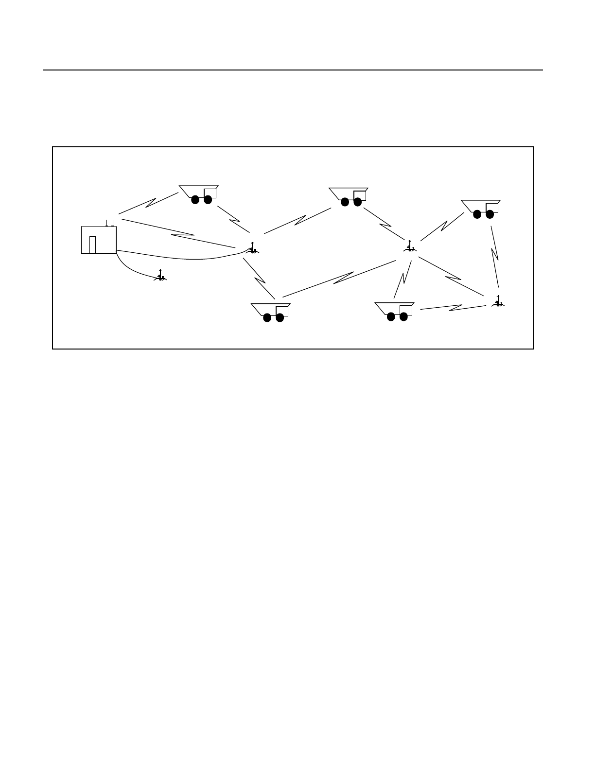
uses several small repeaters, as shown in the following simplified
diagram:
Figure 1 SSR System Configuration, Simplified
Each repeater extends the base station’s area of coverage and
communicates with the base station by way of other repeaters or
directly by way of a fiber optic cable.
The base station uses redundant radios to ensure continued operation
in case a radio fails. Likewise, primary routing paths between
repeaters incorporate alternative routing paths in case a repeater
fails. The mine can optionally add repeaters to provide redundancy to
whatever extent is desired.
Initial installation is expedient in part because the ISM frequency
band is license free, and there are no delays associated with license
applications. Nor are there licensing fees. The system’s inherent
architecture makes adding repeaters to an installed system
practically effortless, and mobile repeaters are easily deployed to
cover new work areas as the mine’s topography changes.
The mobile equipment system and the repeater system are described
in the following sections.
Base
Station
Redundant
Repeater
Ethernet

Spread Spectrum Radio System User’s Manual 3
March 2001
Mobile Equipment
System Each truck, shovel, dozer, drill, or other mine equipment in the
network requires the following major components:
• two 2.4-GHz radios
•a Hub
Although not integral to the SSR system, a CAN-based CGC and a
GPS antenna are also essential units of DISPATCH hardware
required on mine equipment.
Radio Module Two radios are needed per mine vehicle or machine so that 360-degree
coverage is obtained without having an antenna mounted above the
equipment. On a haul truck, the radios are typically mounted on the
front left and right deck or handrails.
Each radio module (Figure 2) consists of a molded plastic case
containing the radio electronics and antenna on the same circuit
board. An internal EMI shield protects the electronics.
Figure 2 Radio Module, External View
The overall dimensions of the unit are 22 by 16.5 by 34.3 centimeters
(8.7 by 6.5 by 13.5 inches) and it weighs only 1.6 kilograms
(3.5 pounds).
Each radio connects to the onboard Hub by way of a cable carrying
power and data signals. The cable connects to a single 6-pin connector
4 Spread Spectrum Radio System User’s Manual
March 2001
on the back of the radio module. The signals are identified in the
following table:
Shielded connections inside the radio encapsulate the LVDS lines so
that radiation is minimized.
Hub The Hub controls the high-speed LVDS links to the radios by way of
FPGAs inside the Hub and the radio modules. The Hub supplies
protected power to the radios as well as protected power to all other
DISPATCH hardware on the mine equipment, such as the CGC and
external Generic Serial Processor (GSP). This eliminates the need for
an external power supply and reduces the amount of input protection
circuitry the non-Hub devices require.
Figure 3 Mobile Equipment Hub
Table 1 Radio Module External Connector
Pin Signal Description
A DATA OUT + LVDS driven from radio +
B DATA OUT −LVDS driven from radio −
C DATA IN −LVDS received from Hub −
D DATA IN + LVDS received from Hub +
E PWR IN 24 V dc received from Hub*
*Acceptable input range is 8 to 38 volts.
F PWR GND Power ground connected to Hub
SLIP
GPS ANTENNA
CAN A
CAN A [RESERVED] RADIO A
RADIO B
POWER
DIGITAL I/OGSPETHERNET

Spread Spectrum Radio System User’s Manual 5
March 2001
The Hub is installed inside the equipment’s cab usually mounted to
the wall or on an upright bracket attached to the floor or rear dash. It
consistsofa rugged case andbaseplate made of castaluminum,which
hasbeenanodized and enameled to provide maximum protectionfrom
harsh environments. Its physical dimensions are approximately 35.4
by 26.2 by 9.4 centimeters (14 by 10.3 by 3.7 inches), and it weighs 4.3
kilograms (9.5 pounds).
Major Circuit Boards
The mobile equipment Hub houses the following major components:
• processor board
This board has an Intel SA1100 processor, DRAM, ROM, flash
memory, FPGA, Ethernet controller (10Base-T), CAN
controller, and other primary components. All transceivers and
isolation components are on the isolation interface board,
thereby making the processor board relatively stable. This
board is also small enough to allow full-size high-precision GPS
receivers to be mounted next to it inside the Hub cover.
• power board
This board distributes protected, isolated, and regulated power
to the system components. The input power source is nominally
12 or 24 V dc. The optional 12-V Hub has an operational range
of 10 to 19 volts; the optional 24-V Hub has an operational
range of 18 to 35 volts.
• connector board
This board provides the internal connections between the
power and isolation interface boards, and all connections to
external devices.
• isolation interface board
This board provides electrical protection and isolation to
signals coming from outside the Hub to the processor.
• location system (GPS) adapter board
This board provides the interface between the processor board
and the GPS receiver.

6 Spread Spectrum Radio System User’s Manual
March 2001
Over and Undervoltage Protection
The Hub power board has built-in protection from damage to the
electronics during a constant steady-state over or undervoltage
condition. When either condition occurs, the Hub shuts off by
disconnecting itself from the power source, and remains off as long as
the accessory switch is open. When the condition no longer exists, and
the accessory switch closes, the Hub turns itself back on.
When the accessory switch opens during normal operation, a soft
shutdown occurs, which permits the software to save data, complete
pending radio communications, and shut down in an orderly fashion.
Connectors and Indicators
There are 11 external connectors on the front of the Hub. A decal
affixed to the top of the Hub indicates the type of connection at each.
One of these connectors is reserved for future use. The other 10 are
briefly described in the following table:
Table 2 Equipment Hub Connectors
Connector Description
GPS ANTENNA type TNC coaxial cable connector for GPS
antenna
SLIP RS-232 service port for laptop during system
startup, update, and troubleshooting
CAN A
(2 connectors) provides power output to and data
communications with standard CAN devices
including CGC and external GSP units;
software configurable to support SAE
standard devices
RADIO A provides power and data link to radio A*
* The radios are configured A or B during software installation.
RADIO B provides power and data link to radio B*
POWER receives source power
DIGITAL I/O provides two digital inputs for contact-
closure-type devices such as foot switches
GSP provides 15-V isolated power to and two
communications ports (A and B) for serial
devices. The A port can be RS-232 or RS-485;
the B port is RS-232.
ETHERNET standard 10Base-T network connection

Spread Spectrum Radio System User’s Manual 7
March 2001
The five status lights on top of the Hub convey important information
to the user. The purpose of each is listed in the following table:
Mobile Equipment
Options The options available with each mobile equipment system include the
following:
• The Hub power system can be either 12 or 24 V dc.
• External multi-protocol CAN-based GSPs can be added to
support more than the two third-party serial devices that the
internal GSP on the Hub processor board satisfies.
• Future enhancements include an external unit that can provide
an analog/digital interface to third-party monitoring equipment
such as oil pressure systems.
Repeater System Several repeater units are required to provide coverage in the work
area. The actual quantity is determined by the user and largely based
on MMS-conducted site surveys. The desired level of redundancy also
impacts the quantity used.
Each repeater unit consists of the following standard components:
• an environmental enclosure containing a Hub with a 1-W,
DSSS, 2.4-GHz radio
• an omnidirectional antenna with a 12-, 18-, or 24-foot mast
• a lightning diverter
Optionally, the user may select
• a steel mounting base
• a wheel option
Table 3 Equipment Hub Status Indicators
Status Light Indication
PWR Hub is receiving power from source.
GPS Link with GPS is operating.
RADIO A Link with radio A is operating.
RADIO B Link with radio B is operating.
COMM Link with mine network is operating.
8 Spread Spectrum Radio System User’s Manual
March 2001
• a solar power system with backup batteries and surge
protection
• an ac-to-dc power system with surge protection
• GPS capability
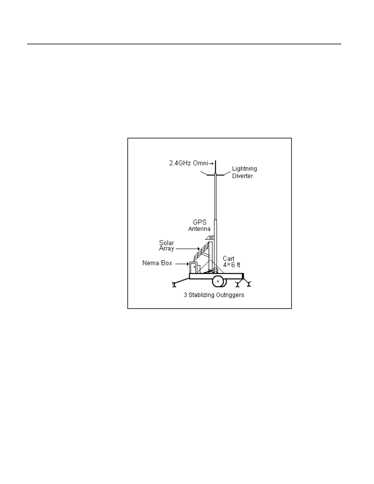
A repeater with optional solar panel and wheels is configured
similarly to the following example:
Figure 4 Example Mobile Repeater
Hub Like the Hub on the mobile equipment, the repeater Hub is made of
cast aluminum that has been anodized and enameled. It is also the
same size as the mobile equipment Hub but is mounted inside an
environmental enclosure that is 50.8 by 40.6 by 20.3 centimeters (20
by 16 by 8 inches) and made of powder-coated 14-gage steel.
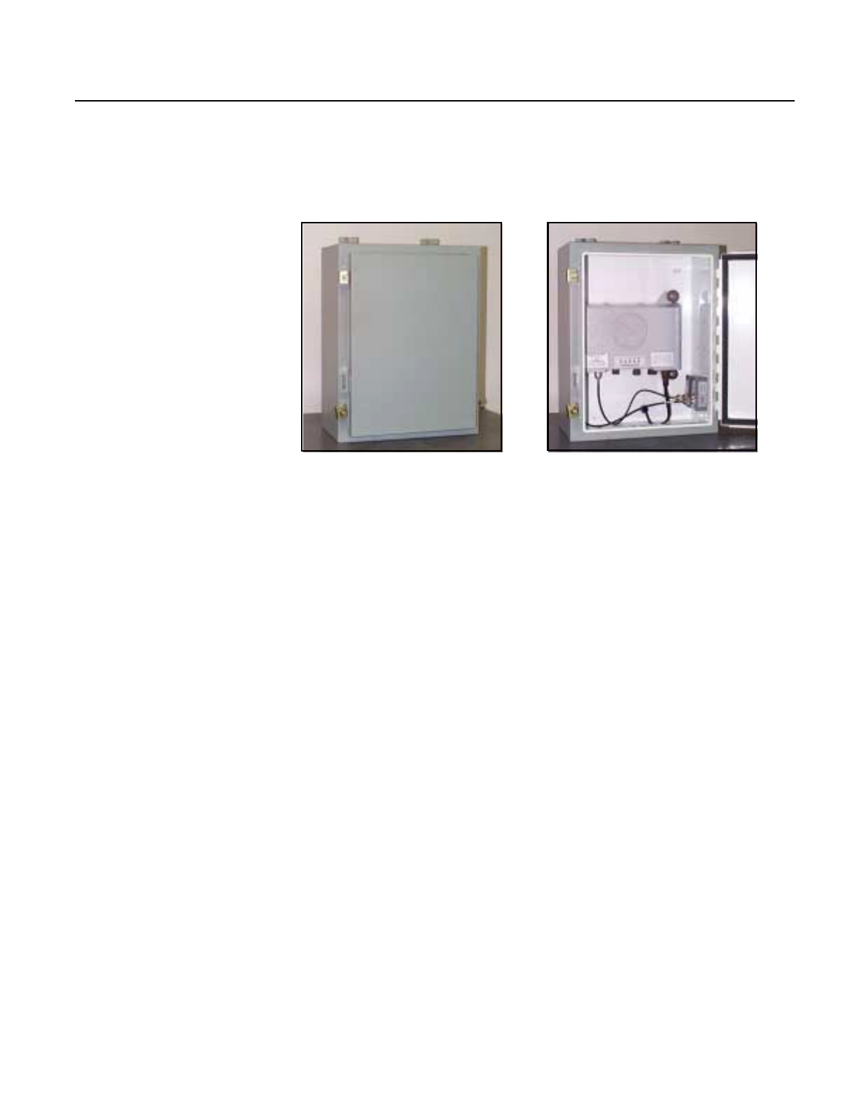
An access door is provided on the front of this NEMA enclosure, and
holes for the antenna coaxial cables and power are provided in the
rear. The enclosure also contains surge suppressors—on the incoming
Spread Spectrum Radio System User’s Manual 9
March 2001
coaxial cables—and the ac-to-dc converter with power line protection
if power is obtained from an ac source rather than the solar panel.
Figure 5 Repeater Hub Environmental Enclosure
A repeater equipped with a solar panel also has backup battery power.
The batteries are installed in a large environmental enclosure. Power
line protection from the solar panel to the Hub in its enclosure is
provided by surge suppressors inside a third enclosure attached to the
enclosure containing the batteries.
Major Circuit Boards
The repeater Hub houses the following major components:
• radio board
The electronics on this board are identical to those on the
mobile system’s radio module. However, this board does not
have an integrated antenna.
• processor board
This is the identical board used in the mobile equipment
system.
• connector board
This board provides the connections between the internal
components and external devices.
Closed Opened
10 Spread Spectrum Radio System User’s Manual
March 2001
• location system (GPS) adapter board
This board is present only if the repeater is equipped with the
GPS option. It provides the interface between the processor
board and the GPS receiver.
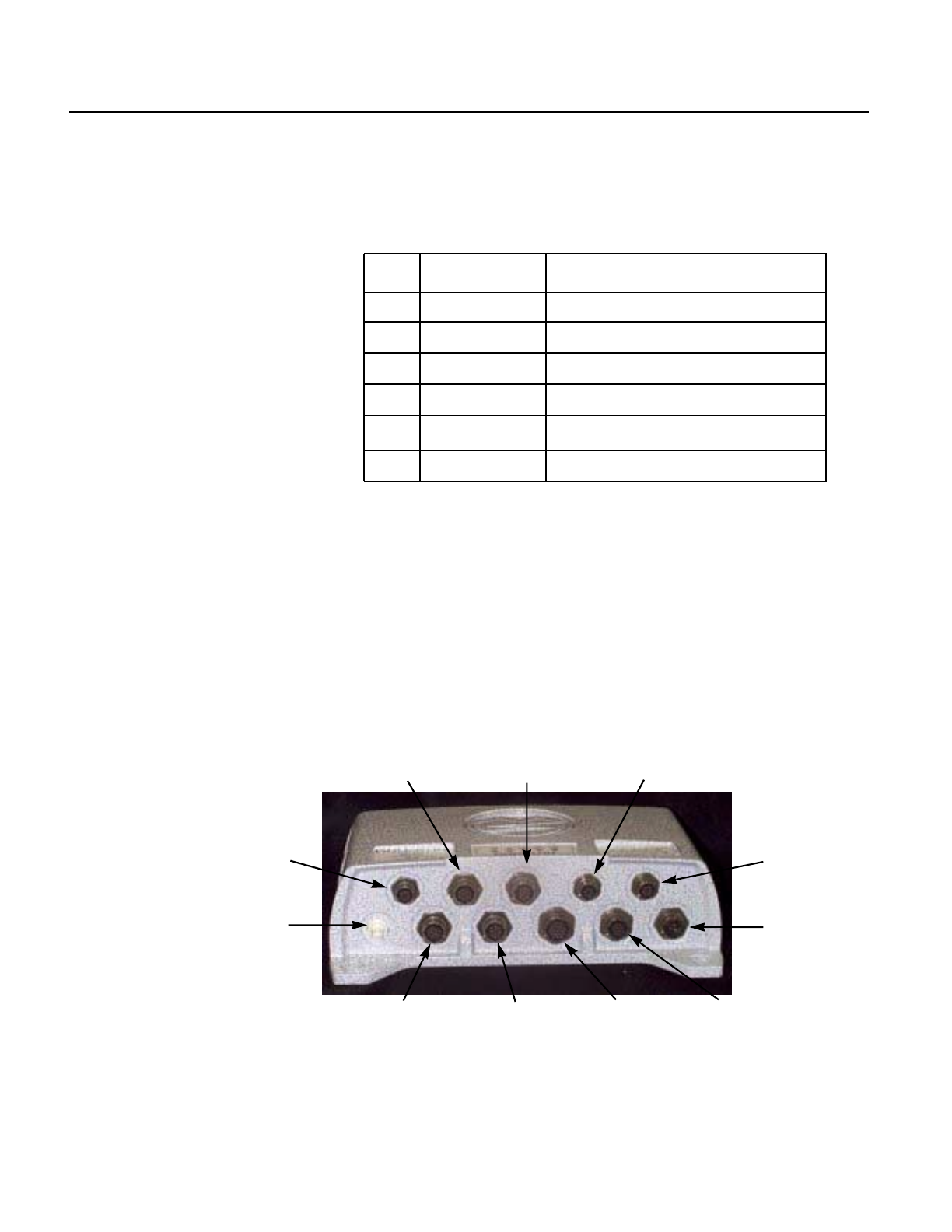
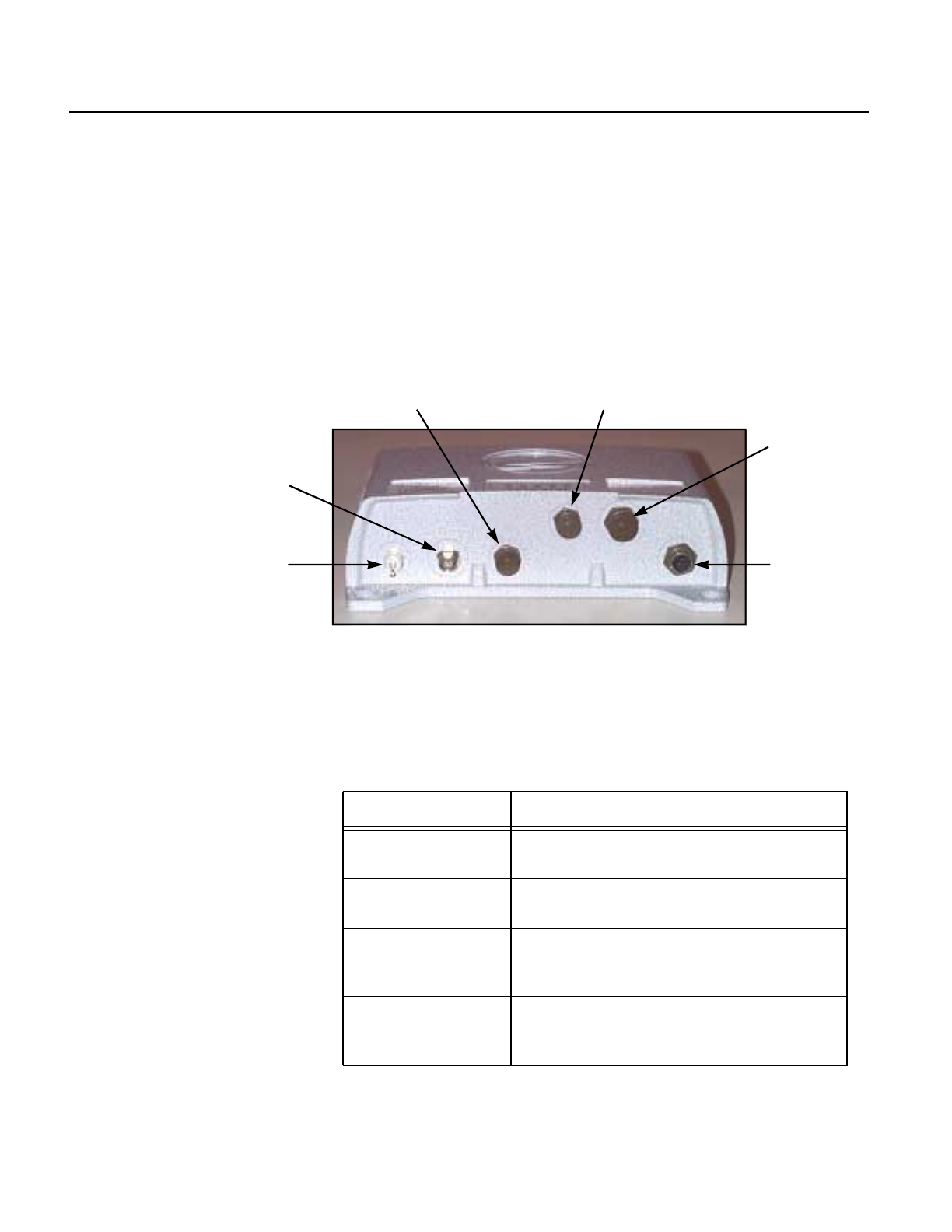
Connectors and Indicators
There are six external connectors on the front of the Hub. A decal
affixed to the top of the Hub indicates the type of connection at each.
Figure 6 Repeater Hub
The following table provides a brief description of each of the
connectors:
RF ANT
GPS ANT
EXT RADIO SLIP
ETHERNET
POWER
Table 4 Repeater Hub Connectors
Connector Description
GPS ANT type TNC coaxial cable connector for GPS
antenna
RF ANT type N coaxial cable connector for 2.4-GHz
radio antenna
EXT RADIO provides connection to an external SSR if an
internal radio is not used. This connector is
normally not used.
SLIP RS-232 service port for laptop connection
during system startup, update, and
troubleshooting
Spread Spectrum Radio System User’s Manual 11
March 2001
The purpose of each status light on top of the Hub is listed in the
following table:
Repeater System
Options The options available with each repeater are as follows:
• A steel base with three stabilizing outriggers and a support for
the antenna mast provides a means for mounting the
electronics, antenna mast, and solar-power system if
applicable. Each outrigger has a jack stand that can be
manually adjusted to suit the level of the terrain.
• A steel frame with two 15-inch wheels and a standard trailer
hitch converts the fixed configuration to a mobile configuration.
This frame mounts below the fixed base to which the
electronics, mast, and solar system are attached. In this
configuration, the repeater can be easily towed and relocated by
pickup or automobile.
ETHERNET fiber optic 10Base-T Ethernet connection
from/to base station
POWER receives 24-V dc operating power either
from solar panels or ac source through ac-to-
dc converter
Table 5 Repeater Hub Status Indicators
Status Light Indication
PWR Hub is receiving power from source.
GPS GPS is operating and LED is blinking the
number of satellites currently being tracked.
LINK The 10Base-T Ethernet link is operating.
LAN The 10Base-T Ethernet LAN is operating.
COMM Link with data radio communications
network in mine is operating.
Table 4 Repeater Hub Connectors (Continued)
Connector Description

12 Spread Spectrum Radio System User’s Manual
March 2001
• Solar power can be provided by way of panels, which are
available in 150-, 200-, and 300-W power ratings. The required
power rating is determined by the repeater’s geographic
location.
• Power can be provided by way of an ac-to-dc converter. When
this option is selected, the converter and surge protection are
physically located in the NEMA enclosure with the Hub. Both
50 and 60 Hz are supported as well as 100- to 120-V ac and 200-
to 240-V ac ranges, which are jumper selectable. The converter
requires 1.3 amps at 100 V ac.
• GPS capability to enable DISPATCH to track a relocated
repeater.
Base Station The repeater Hub is also used as the base station. In this case, the
environmental enclosure is not used because the base station is
normally inside a building, and the antennas are mounted outside.
The power source is hard wired to the Hub through an ac-to-dc
converter. A fiber optic Ethernet connection is used to isolate the base
station computers from the base station Hub, radio, and antennas.
System Installation
and Checkout Installation of the hardware on mine equipment consists of installing
mounting brackets in predesignated locations, and then mounting the
radios and Hubs to the brackets. Cables are then routed and the
connections are made and checked. Neither the Hub nor radios
require being opened.
The repeater base and trailer require some assembly; then the
antenna mast and brackets are installed. After all hardware is
mounted, cable connections are made and checked.
The batteries in the 24-V solar-powered repeater system are charged
by the panels until they reach 28.2 to 29.0 V, and must be charged to
25.4 to 26.6 V dc before the load may be applied. When the batteries
discharge to 22.4 to 23.6 V, the load disconnects. On a fully charged set
of batteries, the repeater can continue operation without sunlight for
several days.
As each mobile equipment system and repeater system is installed,
operating and application software is downloaded from a laptop
through the Hub SLIP port. Then the RF links to the base station or
another communications node are checked to verify throughput is
acceptable.

Spread Spectrum Radio System User’s Manual 13
March 2001
Details on installation and checkout procedures are provided in a
separate manual.
User Interface The status of any and all repeaters in the system configuration can be
monitored from the DISPATCH central computer.

March 2001
A
Acronyms
The acronyms listed in the following table are used in this manual:
Table A.1 Acronyms Used in This Manual
Acronym Definition
CAN Controller Area Network
CGC Color Graphics Console
DRAM dynamic random access memory
DSSS direct sequence spread spectrum
EMI electromagnetic interference
FPGA field-programmable gate array
GPS Global Positioning System
GSP Generic Serial Processor
ID identification
ISM Industrial, Scientific, and Medical
LVDS low-voltage differential signal
MMS Modular Mining Systems
NEMA National Electrical Manufacturers Association
PCB printed circuit board
ROM read-only memory
SAE Society of Automotive Engineers
SSR spread spectrum radio
VSMS Vital Signs Monitoring System

March 2001
B
Radio Module
Specifications
General
Description The 2.4-GHz DSSS spread spectrum radio is based on the Intersil
PRISM I chipset (Intersil was formally Harris). The Intersil PRISM I
information can be found at the following Web site:
www.intersil.com/prism/ (Select PRISM I * 2 Mb/s product link.)
Because MMS used the Intersil design for the radio, most of the
specifications in this appendix are directly from Intersil
documentation. However, two major areas differ and are reflected in
these specifications
• MMS replaced the Intersil PA/switch chip with a new amplifier
design and a separate antenna switch.
• The radio has no MAC (Media Access Controller) chip and,
instead, is controlled through a custom link with the Hub
(MMS computer).
MMS replaced the Intersil PA/switch chip to achieve 1 watt of output
power (the maximum permitted by the FCC) instead of just 18 dBm.
The additional power provides an increased range so that the radios
can be used in an open-pit mine with line-of-sight being
approximately 8 miles node to node. As required by the FCC for radios
with over 20 dBm (100 mW) of power, the power setting is adjustable.
The controlling link is a 22-Mb/s LVDS digital link between the radio
and the Hub. The radio must be connected to the Hub, and the radio
board has a built-in antenna. As an option, MMS would like to cut the
antenna off the board and use an omnidirectional antenna.
MMS plans to sell approximately 2100 of the PRISM I radio design
before exploring the PRISM II design from Intersil.

B-2 Spread Spectrum Radio System User’s Manual
March 2001
Functional
Specifications The radio operates in the license-free 2.400- to 2.4835-GHz ISM
(Industrial, Scientific, Medical) frequency band and is capable of two
data rates
• DBPSK Differential Binary Phase Shift Keying 1 Mb/s
• DQPSK Differential Quadrature Phase Shift Keying 2 Mb/s
Tables B.1 through B.4 list the radio module specifications:
Table B.1 Radio Supply Power
Specification Typical Unit
Power Voltage Input Range (acceptable) 9–38 volts DC
Radio Module Input Voltage from Hub (controlled via
Hub) 24 volts DC
Radio Module Power (receive mode only) 1.43 watts
Radio Module Power (full 98% TX duty cycle) 4.7 watts
Radio Module Power (typical 20% duty cycle)a2.1 watts
a. Power = 1.43 + (3.4 ∗ duty cycle) watts
Table B.2 Radio RF Performance and Operation
Specification Typical Unit
Output Power Range 2–30 dBm
Output Power Resolution (8-bit DAC) 256 steps
TX Distance Range (based on 2–30 dBm) 0.3–8.0 miles
B.E.R. 1 × 10-6 bits
Processing Gain (per 11-bit chipping code) 10.4 dB
Image Rejection 80 dB
Adjacent Channel Rejection >35 dB
Receiver Noise Figure 7 dB
Channel Noise (N=kTB where B=2 MHz despread) −110.97 dBm
Signal-to-Noise Ratio (SNR-Eb/No∗ R/BT) 11.1 dBm
Receiver Sensitivity (= noise floor + SNR) −92.87 dBm

Appendix B — Radio Module Specifications B-3
March 2001
Dynamic Range (TX power −receiver sensitivity) 122.87 dB
Transmit Spectral Mask (at 1st side-lobe) −30 dBr
TX & RX Data Rates Using DBPSK 1 Mb/s
TX & RX Data Rates Using DQPSKa2 Mb/s
Chipping Code (currently is a 802.11 compatible Barker) 11 chips
Key-up (synchronization − must be at DBPSK data rate) 128 bits (& µs)
Maximum Packet Sizeb1024 bytes
Output Power Resolution (8-bit DAC) 128 steps
Channels 12 —
Channel Separationc5MHz
IF Frequency 280 MHz
LO VCO Frequency (= 2 × IF) 560 MHz
a. Default operation will be DQPSK.
b. The 128-bit synchronization header is not counted.
c. Channels start at 2412 MHz and increment in 5-MHz steps (802.11 style).
Table B.2 Radio RF Performance and Operation (Continued)
Specification Typical Unit
Table B.3 Radio Physical Specifications
Specification Typical Unit
Overall Module Size (L × W × H) 8.7 × 6.5 × 13.5 inches
Overall Weight 3.5 pounds
Backplate (structural foam using Valox FV649) 0.75 pounds
Cover (Valox 357) 1.53 pounds
PCB Dimensions (W × H) 6.5 X 9.6 inches
PCB Construction – 0.093" FR4 6 layer —
Operational Temperature Range −30 to +60 Celsius
B-4 Spread Spectrum Radio System User’s Manual
March 2001
FCC Items To pass FCC regulations, the radio must pass a stringent set of
standards set forth in the following document:
FCC Title 47 part 15, in particular the following sections:
• section 203 – antenna requirement
• section 209 – radiated emissions outside of band (general)
• section 247 – operation within band (all aspects)
• section 249 – operation within band (field strength)
The following table presents several key test parameters that have
been verified:
Table B.4 Radio Antenna Performance
Specification Typical Unit
Antenna Type = Integrated Quad Vivaldi on FR4 — —
AZ 3-dB Beam width 190 degrees
EL 3-dB Beam width 28 degrees
Gain 6 dB
Feed Structure Losses (0.3 dB per inch on 0.030" FR4) 1.5 dB
Table B.5 Verified FCC Test Parameters
Parameter Typical Unit
Spectral Sideband Suppression 30 dBr
Max Antenna Gain 6 dB
Max Transmit Power 30 dBm
Outside of Frequency Band Emissions Attenuation ≥50 dB

Appendix B — Radio Module Specifications B-5
March 2001
Channel
Definitions The channel selection is identical to the 802.11 standard, which is as
follows:
See the “DSSS Channels and Regulations” section for detail.
Table B.6 Channel Definitions
Channela
a. Each channel has a 17-MHz bandwidth.
Onboard
RF VCOb
b. The onboard RF VCO output is always
the Transmit Freq − IF Freq (280 MHz).
Transmit
Frequency
1 2132 MHz 2412 MHz
2 2137 MHz 2417 MHz
3 2142 MHz 2422 MHz
4 2147 MHz 2427 MHz
5 2152 MHz 2432 MHz
6 2157 MHz 2437 MHz
7 2162 MHz 2442 MHz
8 2167 MHz 2447 MHz
9 2172 MHz 2452 MHz
10 2177 MHz 2457 MHz
11 2182 MHz 2462 MHz
Japan 2204 MHz 2484 MHz

B-6 Spread Spectrum Radio System User’s Manual
March 2001
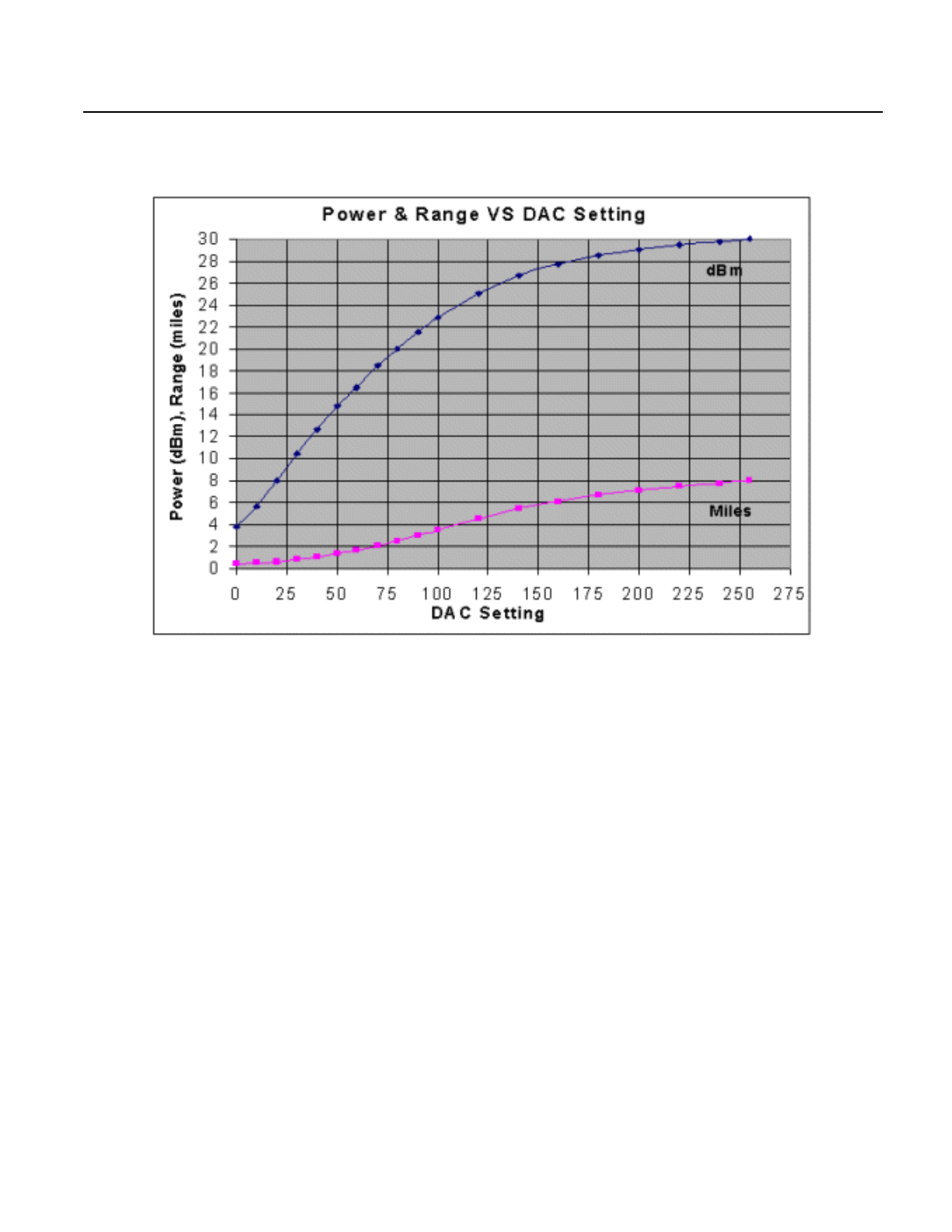
Power and
Distance The following table and diagram show data pertaining to the power
output versus gain control input:
Table B.7 Power vs. Range
Setting
DAC Power
dBm Power
mW Range
Miles Range
km
0 3.85 2.43 0.39 0.63
10 5.70 3.72 0.49 0.78
20 8.01 6.32 0.64 1.02
30 10.49 11.19 0.85 1.36
40 12.67 18.50 1.09 1.75
50 14.81 30.29 1.39 2.24
60 16.47 44.38 1.69 2.71
70 18.45 70.01 2.12 3.41
80 19.99 99.81 2.53 4.07
90 21.53 142.12 3.02 4.85
100 22.84 192.16 3.51 5.64
120 25.06 320.63 4.53 7.29
140 26.68 465.94 5.46 8.79
160 27.71 590.43 6.15 9.89
180 28.48 705.23 6.72 10.81
200 29.04 801.99 7.16 11.53
220 29.47 884.78 7.52 12.11
240 29.78 950.97 7.80 12.55
255 30.00 1000.00 8.00 12.87
Appendix B — Radio Module Specifications B-7
March 2001
B-8 Spread Spectrum Radio System User’s Manual
March 2001
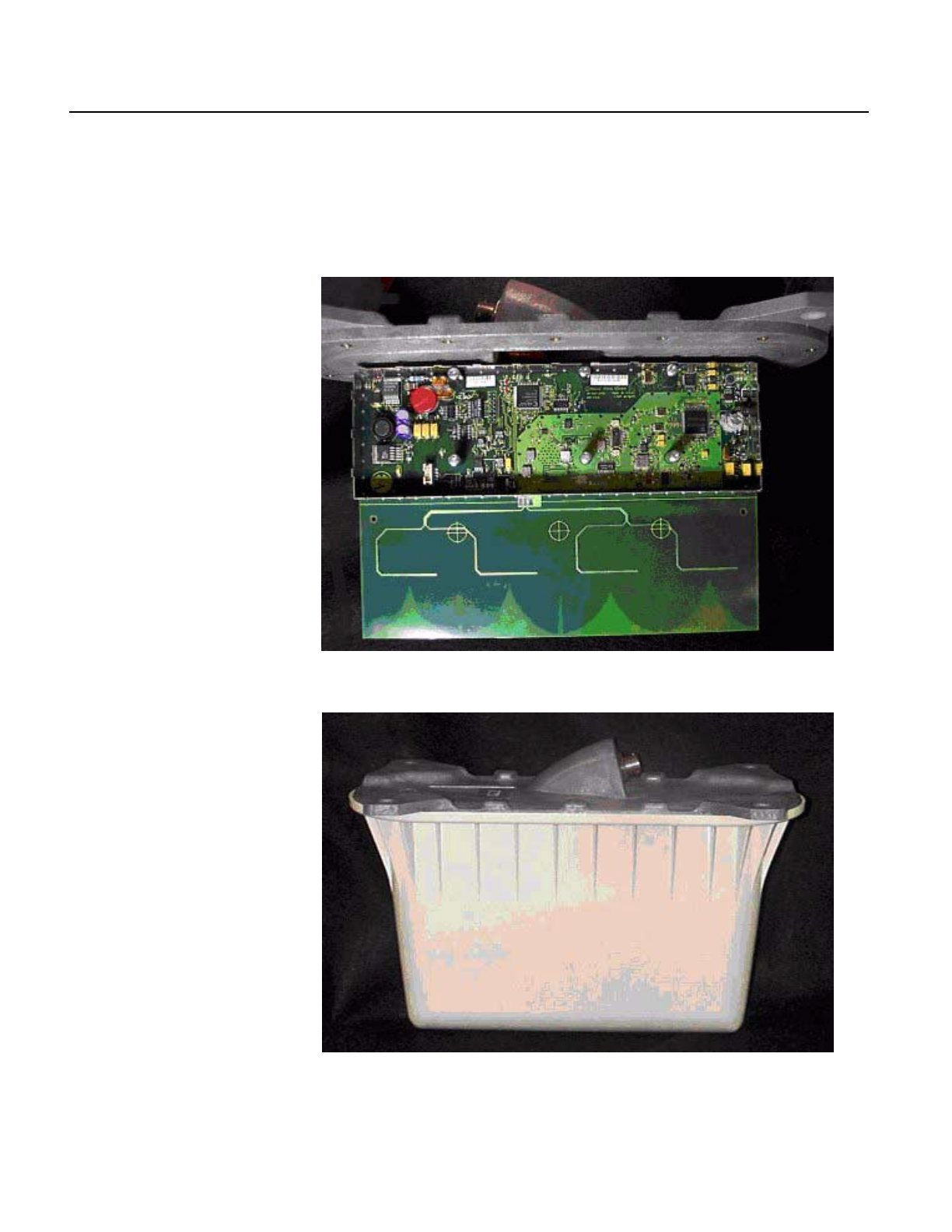
Photographs As shown in the following photograph, the radio is basically a
PRISM I chipset with a 1-watt amplifier and a power supply. The
FPGA controls the radio by way of the digital serial link from the Hub
computer.
The following photograph shows the radio with its plastic cover on.
Appendix B — Radio Module Specifications B-9
March 2001
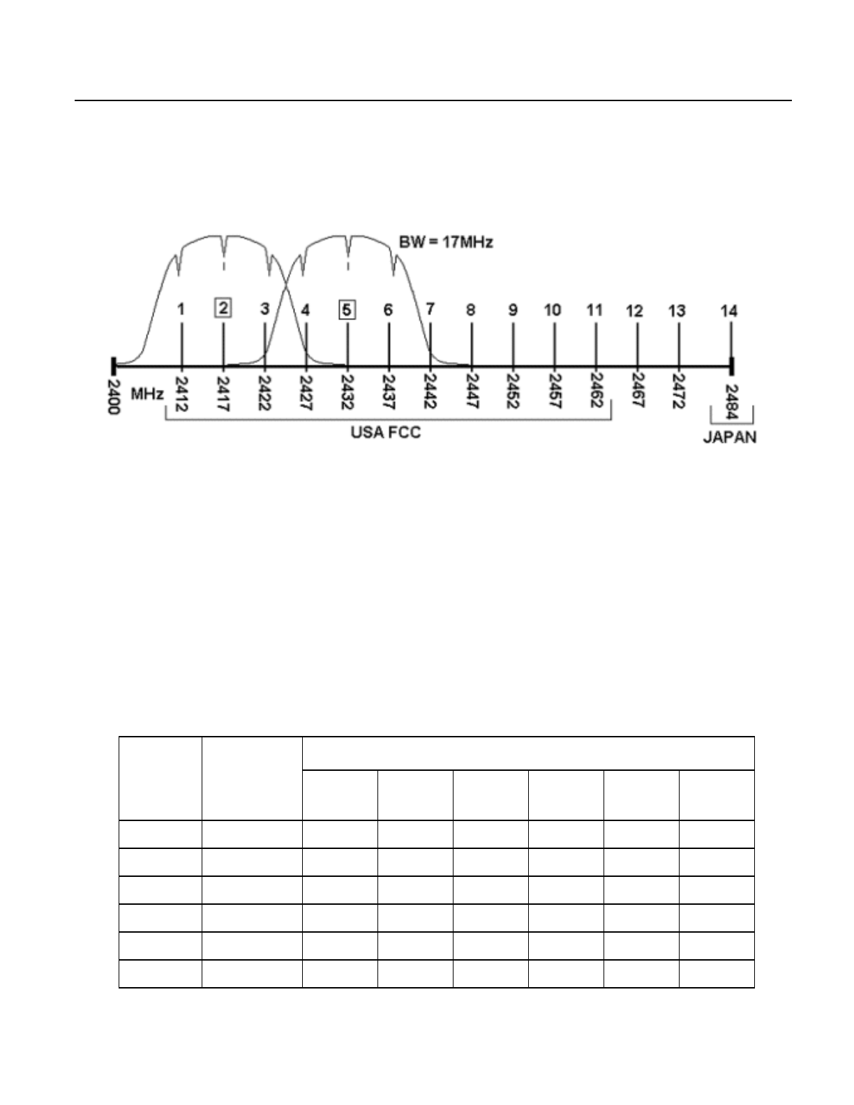
DSSS Channels and
Regulations The following diagram and table show frequency band allocation:
USA: ISM Band 2400-2483.5 MHz (Same for Europe – ETSI)
Power 1 watt maximum (30 dBm)
Directivity 6 dB antenna gain maximum
JAPAN: ISM Band 2471 – 2497 MHz
Power 10 mW / MHz
Note: The microwave oven operates at 2.43 GHz. Also, the two other ISM
bands in the U.S.A. are 902–928 MHz and 5725–5850 MHz.
Table B.8 Frequency Band Allocation
Channel
ID Frequency
(MHz)
Regulatory Domains
X'10'
FCC X'20'
IC X'30'
ETSI X'31'
Spain X'32'
France X'40'
MKK
1 2412 X X X - - -
2 2417 X X X - - -
3 2422 X X X - - -
4 2427 X X X - - -
5 2432 X X X - - -
6 2437 X X X - - -
0
Radio Module Specifications

B-10 Spread Spectrum Radio System User’s Manual
March 2001
7 2442 X X X - - -
8 2447 X X X - - -
9 2452 X X X - - -
10 2457 X X X X X -
11 2562 X X X X X -
12 2467 - - X - X -
13 2472 - - X - X -
14 2484 - - - - - X
Table B.8 Frequency Band Allocation (Continued)
Channel
ID Frequency
(MHz)
Regulatory Domains
X'10'
FCC X'20'
IC X'30'
ETSI X'31'
Spain X'32'
France X'40'
MKK
Appendix B — Radio Module Specifications B-11
March 2001
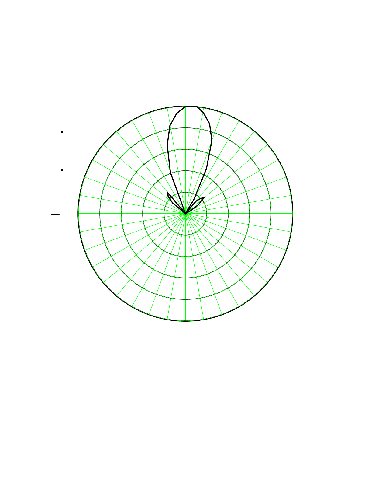
EL Antenna
Pattern
Antenna Parameters:
Plot File polar_data_74E_5ea.MCD
Title Quad Element Vivaldi
Radius 1.45"
Separation 2.400" per element (1/2 λ)
Element Gap 0.100"
Element 2.300"
0
10
20
30
40
50
60
70
80
90
100
110
120
130
140
150
160
170
180
190
200
210
220
230
240
250
260 270 280
290
300
310
320
330
340
350
17.5
14
10.5
7
3.5
0
17.5
0
ti
θi
B-12 Spread Spectrum Radio System User’s Manual
March 2001
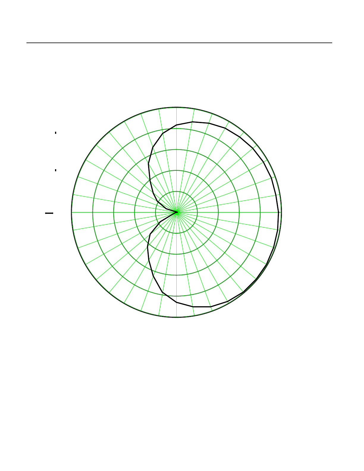
AZ Antenna
Pattern
Antenna Parameters:
Plot File polar_data_74H.MCD
Title Quad Element Vivaldi
Radius 1.45"
Separation 2.400" per element (1/2 λ)
Element Gap 0.100"
Element 2.300"
0
10
20
30
40
50
60
70
80
90
100
110
120
130
140
150
160
170
180
190
200
210
220
230
240
250
260 270 280
290
300
310
320
330
340
350
17.5
14
10.5
7
3.5
0
17.5
0
ti
θi

Revision History
Revision Date Comments
— March 2001 First issue