Modular Mining Systems 302230 Spread Spectrum Transmitter User Manual Manual Page 1 to 13
Modular Mining Systems Inc Spread Spectrum Transmitter Manual Page 1 to 13
Contents
Manual Page 1 to 13

Foreman
PC
Hardware Installation Guide
Revision A: October 2002
Part Number 201265

RESTRICTIVE COVENANT
AND
DISCLAIMER
Copyright © 2002 by Modular Mining Systems, Inc.
Tucson, Arizona, U.S.A.
All rights reserved.
Modular Mining Systems, Inc., makes no representation regarding the fitness, quality, design, condition,
capacity, suitability, or performance of the equipment or of the material or workmanship thereof and/or compliance of
the system with the requirements of any law or regulations, and disclaims all warranties, either express or implied,
including but not limited to any implied warranty of merchantability or fitness for any particular purpose. Modular
Mining Systems, Inc., shall not be responsible for any loss or damage to property or injury or death to persons caused
by any defect or failure in the system hardware and/or software regardless of the form of action, whether in contract or
in tort, including negligence, strict liability, or otherwise. Modular Mining Systems, Inc., is not responsible for any
losses, financial or otherwise, that the customer, purchaser, or end user (hereafter, collectively, user) incurs nor shall it
be liable for any damages whatsoever (including, without limitation, damages for loss of business or investment profits,
business interruption, loss of business information or the like) arising out of the use, interruption in the use of, or
performance of the system hardware and/or software. User expressly agrees to indemnify and hold harmless Modular
Mining Systems, Inc., from and against all claims, damages, losses, and expenses, including but not limited to: (i) any
loss resulting from general or particular requirements of needs of user as defined in user’s originating purchase order;
(ii) any damages from loss of use, loss of data, loss of profits, or loss of business arising out of or in connection with the
performance of system hardware and/or software; (iii) any loss or damage to property or injury or death to persons
proximately resulting from system hardware and/or software, even if entirely due in whole or in part to negligent acts
or omissions of Modular Mining Systems, Inc.; and (iv) attorney’s fees and costs.
The information described in this document is furnished as proprietary information and may not be copied or sold
without the written permission of Modular Mining Systems, Inc.
Trademarks
The Modular distinctive font, MasterLink, ProVision, and WebReports are trademarks of Modular Mining Systems, Inc.
The Modular logo, DISPATCH, and IntelliMine are registered U.S. trademarks of Modular Mining Systems, Inc.
All other brand names and product names used in this book are trademarks, registered trademarks, or trade
names of their respective holders.

MANDATORY SAFETY INSTRUCTIONS TO INSTALLERS AND USERS
Use only antennas supplied by Modular Mining Systems or dealer.
Antenna Minimum Safe Distance: 20 cm
Antenna Gain: Zero dBd referenced to a dipole.
The Federal Communications Commission has adopted a safety standard for
human exposure to RF (Radio Frequency) energy which is below the OSHA
(Occupational Safety and Health Act) limits.
Antenna Mounting: The antenna supplied by Modular Mining Systems or
dealer must not be mounted at a location such that during radio transmission,
any person or persons can come closer than the above minimum safe distance
to the antenna, i.e. 20cm.
To comply with current FCC RF exposure limits, the antenna must be installed at
or exceeding the minimum safe distance shown above, and in accordance with
the requirements of the Modular Mining Systems.
1. Mag Mount Roof-top Installation: The Mag mounted antenna assembly
should be placed on the roof of the automobile. The 5 foot extension rod
should not be modified.
2. Permanent Roof-top Installation: The magnetic base may be removed from
the antenna assembly, however, the base of the assembly should be mounted
to the top of the automobile so that the antenna is at least 4 feet over the roof.
The 5 foot extension rod should not be modified.
Antenna substitution: Do not substitute any antenna for the one supplied or
recommended by Modular Mining Systems. You may be exposing person or
persons to harmful radio frequency radiation. You may contact Modular Mining
Systems for further instructions.
WARNING: Maintain a separation distance from the antenna to person(s) of at
least 20cm.
You, as the qualified end-user of this radio device must control the exposure
conditions of bystanders to ensure the minimum separation distance (above) is
maintained between the antenna and nearby persons for satisfying RF Exposure
compliance. The operation of this transmitter must satisfy the requirements of
Occupational / Controlled Exposure Environment, for work-related use. Transmit
only when person(s) are a least the minimum distance from the properly
installed, externally mounted antenna.

Contents
iii Revision A: October 2002
About This Manual . . . . . . . . . . . . . . . . . . . . . . .v
Audience. . . . . . . . . . . . . . . . . . . . . . . . . . . . . . . . . . . . . . . . . . . . . .v
Chapter Table . . . . . . . . . . . . . . . . . . . . . . . . . . . . . . . . . . . . . . . . .v
1 Introduction . . . . . . . . . . . . . . . . . . . . . . . . . . . 1-1
What is the Foreman PC?. . . . . . . . . . . . . . . . . . . . . . . . . . . . . . 1-3
2 Hardware Installation . . . . . . . . . . . . . . . . . . 2-1
Tools Required. . . . . . . . . . . . . . . . . . . . . . . . . . . . . . . . . . . . . . . 2-3
Overview . . . . . . . . . . . . . . . . . . . . . . . . . . . . . . . . . . . . . . . . . . . 2-3
Installing the PC . . . . . . . . . . . . . . . . . . . . . . . . . . . . . . . . . . . . . 2-5
Installing the PC Pedestal . . . . . . . . . . . . . . . . . . . . . . . . . . 2-5
Using a Transmission Hump Assembly . . . . . . . . . . . . . 2-6
Using Floor Mount Bracket. . . . . . . . . . . . . . . . . . . . . . . 2-8
Installing the PC Mount and PC . . . . . . . . . . . . . . . . . . . . 2-11
Mounting the Electrical Box. . . . . . . . . . . . . . . . . . . . . . . . . . . . 2-8
Mounting the GPS Receiver (part of 302184) . . . . . . . . . . . . . . 2-9
Mounting the RF Antenna . . . . . . . . . . . . . . . . . . . . . . . . . . . . 2-10
Connecting Cables. . . . . . . . . . . . . . . . . . . . . . . . . . . . . . . . . . . 2-12
Connecting the RF Feedline (302255) to the RF Antenna 2-13
Running the RF Antenna and GPS Receiver Cables into the
Cab . . . . . . . . . . . . . . . . . . . . . . . . . . . . . . . . . . . . . . . . . . . . 2-13
Connecting Cable 302188 to PC . . . . . . . . . . . . . . . . . . . . . 2-14
Connecting the PC Power Cable (part of part number 302184)
. . . . . . . . . . . . . . . . . . . . . . . . . . . . . . . . . . . . . . . . . . . . . . . 2-14
Connecting the Electrical Box Power Cable (302203) . . . . 2-17
Connecting the Attenuator (105919) . . . . . . . . . . . . . . . . . 2-18
Connecting the RF Feedline (302255) to Electrical Box . . 2-20

Foreman PC Hardware Installation Guide
iv
Revision A: October 2002
Appendix A - Drawings and SCDs . . . . . . . . A-1
Appendix B - Bill of Materials . . . . . . . . . . . B-1
Appendix C - Installation Kit . . . . . . . . . . . . C-1

vRevision A: October 2002
About This Manual
Welcome to the Foreman PC Hardware Installation Guide. This
manual provides step-by-step instructions for installing the
IntelliMine Foreman PC hardware.
Audience This manual is written for mine technicians experienced in installing
Modular hardware.
Chapter Table This manual contains two chapters and three appendixes.
Chapter 1, Introduction, provides an overview of the Foreman PC.
Chapter 2, Hardware Installation, provides step-by-step
instructions for installing the PC hardware, including the vehicle-
specific mounting pedestal, touch-screen monitor and keyboard, and
GPS and RF antennas.
Appendix A, Drawings and SCDs, contains cable drawings and
SCDs.
Appendix B, Bill of Materials, contains the BOMs for the hardware
installation.
Appendix C, Installation Kit, contains the BOM of the installation
kit used to install the Foreman PC system hardware.

Revision A: October 2002
1
Introduction
What is the Foreman PC? . . . . . . . . . . . . . . . . . . . . . . . . . . . . . . . . .1-3

Revision A: October 2002
1
Introduction
What is the
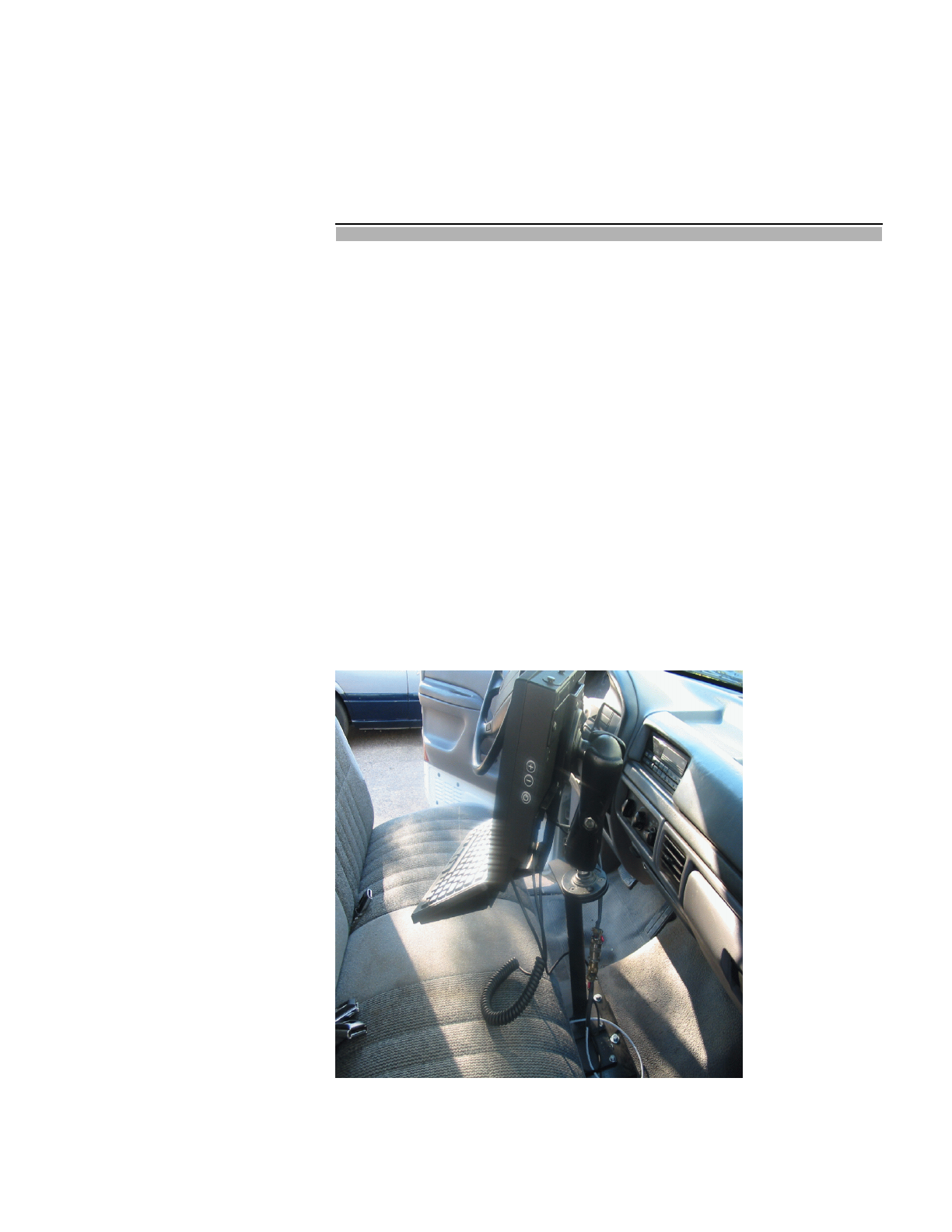
Foreman PC? The IntelliMine Foreman PC is a ruggedized PC installed in the cab
of a pickup truck or other designated foreman’s vehicle. The Foreman
PC provides
• IntelliMine dispatcher and foreman utilities for controlling and
monitoring the haulage operation
• MasterLink diagnostic utilities
• IntelliMine maintenance utilities (in mines using the
IntelliMine MineCare system)
• Corporate applications, such as mine email.
• Internet Explorer
Figure 1.1 Foreman PC

1-4 Foreman PC Hardware Installation Guide
Revision A: October 2002
The Foreman PC runs the Windows 2000 operating system and allows
both touch-screen and keyboard operation. It has a Pentium 3
processor (500 Mhz) and a solid state flash disk for high-vibration
applications. The PC’s chargeguard timer shuts down the computer
when the computer is not in use (after a user-defined interval) to
protect the vehicle’s battery.
For easy installation, the Foreman PC includes a vehicle-specific
mounting pedestal. The PC communicates with the IntelliMine
system via a 2.4 GHz Cisco 802.11 radio and a one watt RF power
amplifier.

Revision A: October 2002
2
Hardware Installation
Tools Required . . . . . . . . . . . . . . . . . . . . . . . . . . . . . . . . . . . . . . . . . .2-3
Overview. . . . . . . . . . . . . . . . . . . . . . . . . . . . . . . . . . . . . . . . . . . . . . .2-3
Installing the PC . . . . . . . . . . . . . . . . . . . . . . . . . . . . . . . . . . . . . . . .2-5
Installing the PC Pedestal. . . . . . . . . . . . . . . . . . . . . . . . . . . . . .2-5
Using a Transmission Hump Assembly . . . . . . . . . . . . . . . .2-6
Using a Floor Mount Bracket . . . . . . . . . . . . . . . . . . . . . . . .2-8
Installing the PC Mount and PC. . . . . . . . . . . . . . . . . . . . . . . .2-11
Mounting the Electrical Box (302230) . . . . . . . . . . . . . . . . . . . . . .2-12
Mounting the GPS Receiver (part of 302184). . . . . . . . . . . . . . . . .2-13
Mounting the RF Antenna (302189 ) . . . . . . . . . . . . . . . . . . . . . . .2-14
Connecting Cables . . . . . . . . . . . . . . . . . . . . . . . . . . . . . . . . . . . . . .2-16
Connecting the RF Feedline (302255) to the RF Antenna . . . .2-17
Running the RF Antenna and GPS Receiver Cables into the
Cab . . . . . . . . . . . . . . . . . . . . . . . . . . . . . . . . . . . . . . .2-17
Connecting Cable 302188 to PC . . . . . . . . . . . . . . . . . . . . . . . .2-18
Connecting the PC Power Cable (part of part number 302184). . . . 2-18
Connecting the Electrical Box Power Cable (302203) . . . . . . .2-21
Connecting the Attenuator (105919). . . . . . . . . . . . . . . . . . . . .2-22
Connecting the RF Feedline (302255) to Electrical Box. . . . . .2-24

Revision A: October 2002
2
Hardware Installation
Tools Required To install the Foreman PC system hardware, you need to use
Modular’s hardware installation kit (part number 200602). Tools
provided in the kit (see Appendix C) include:
• a 20AWG pin insertion tool
• a 20AWG pin extraction tool
• a coaxial wire stripper
• military pin crimpers
• a drill and bits
Overview The main hardware components of the Foreman PC system are:
• A ruggedized PC and keyboard mounted on an adjustable PC
mount in the cab
• An RF antenna on the cab roof that provides serial
communications to the PC
• A GPS receiver/antenna on the cab roof that provides GPS data
to the PC
• An electrical box (enclosure) behind the cab seat that, among
other things, provides power to the PC and relays information
to the PC from the RF antenna
Installing the Foreman PC entails mounting the above components in
place and connecting them with cables. The installation also includes
connecting the electrical box to an unswitched, continuous 12-volt
power source inside the cab or direct to the truck battery.
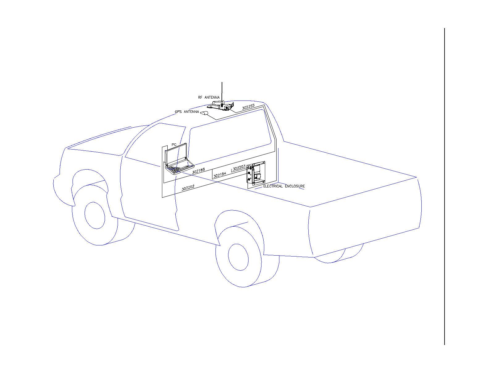
Figure 2.1 on the following page shows the hardware locations and
cable connections. Subsequent sections in this chapter provide step-
by-step instructions for installing the hardware and cables.

2-4 Foreman PC Hardware Installation Guide
Revision A: October 2002
Figure 2.1 Foreman PC Hardware Locations and Cable Connections
302184
(Connectors shown side exit
for illustration only. Connectors
exit down.)

Chapter 2 — Hardware Installation 2-5
Revision A: October 2002
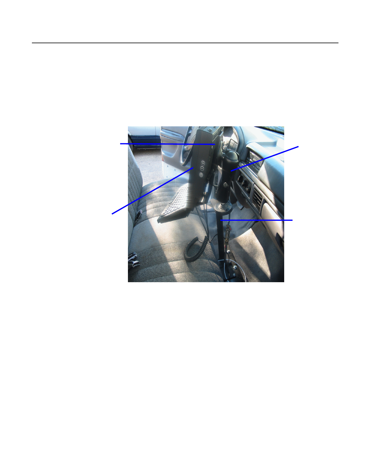
Installing the PC The Foreman PC comes with a vehicle-specific pedestal that serves as
a base for the PC. An adjustable PC mount attaches to the pedestal in
order to hold the PC in place. The mount swivels and allows virtually
any adjustment for optimum positioning of the PC. To connect the
adjustable mount to the PC, you install a bracket to the back of the PC
and then attach the mount to the bracket.
Figure 2.2 PC Installation Overview
Installing the PC comprises the following basic tasks:
• Installing the pedestal
• Installing the PC mount and PC
Installing the PC
Pedestal There are two ways to install the PC pedestal:
• You can mount the pedestal in the cab, using a transmission
hump assembly (this is typically for trucks with bench seats)
or
• You can mount the pedestal in the cab, using a floor mount
bracket, which attaches to one or two of the seat bolts (this
is for Ford F250/F350 series trucks)
PC mounting
bracket
PC
Adjustable
PC mount
Vehicle-specific
pedestal