Modular Mining Systems 302230 Spread Spectrum Transmitter User Manual Manual Page 31
Modular Mining Systems Inc Spread Spectrum Transmitter Manual Page 31
Contents
Manual Page 31
Chapter 2 — Hardware Installation 2-23
Revision A: October 2002
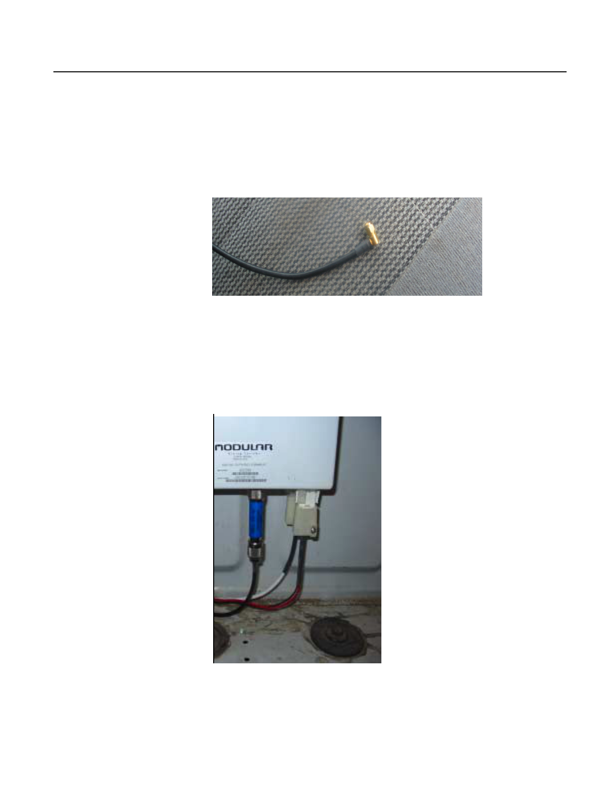
Once the attenuator is installed, you must connect cable 302202
(drawing 403516) to the attenuator and to the top of the PC to connect
the antenna to the built-in 2.4 GHz Cisco radio. Cable 302202 is
terminated at one end, as shown below. Minimize cable 302202 for
maximum power (six foot minimum for FCC compliance).
Figure 2.23 Terminated End of Cable 302202
2Terminate the other end of cable 302202, as shown in drawing
403516.
3Attach the terminated end to the attenuator and attach the other
end to the top of the PC. Make sure the bend radius is 3 - 4 inches.
Figure 2.24 Cable 302202 Attached to Attenuator