Motorola Solutions 89FT7623 5400xxyyzzab User Manual Operations guide pt 1
Motorola Solutions, Inc. 5400xxyyzzab Operations guide pt 1
UserManual.wiki
>
Motorola Solutions
>
89FT7623 User Manual
>
Operations guide pt 1
Contents
1.
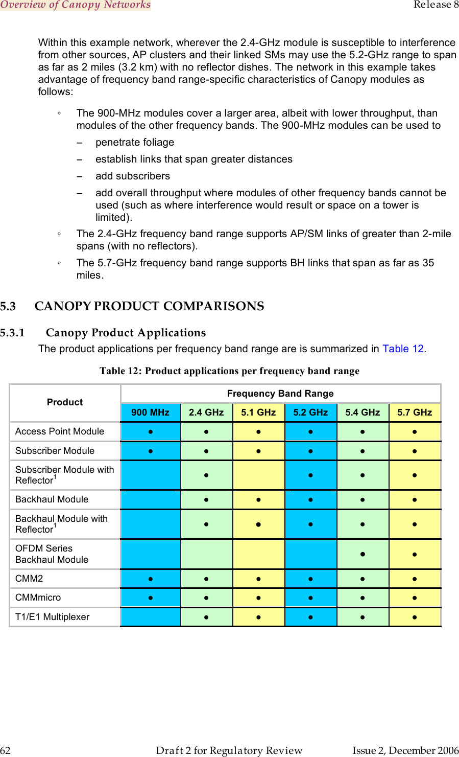
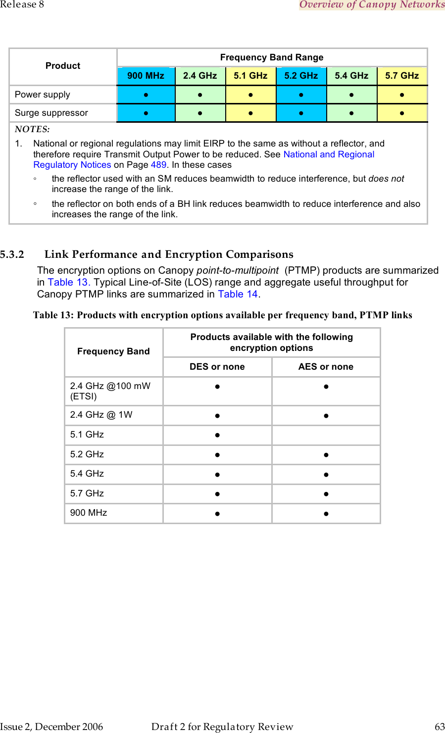
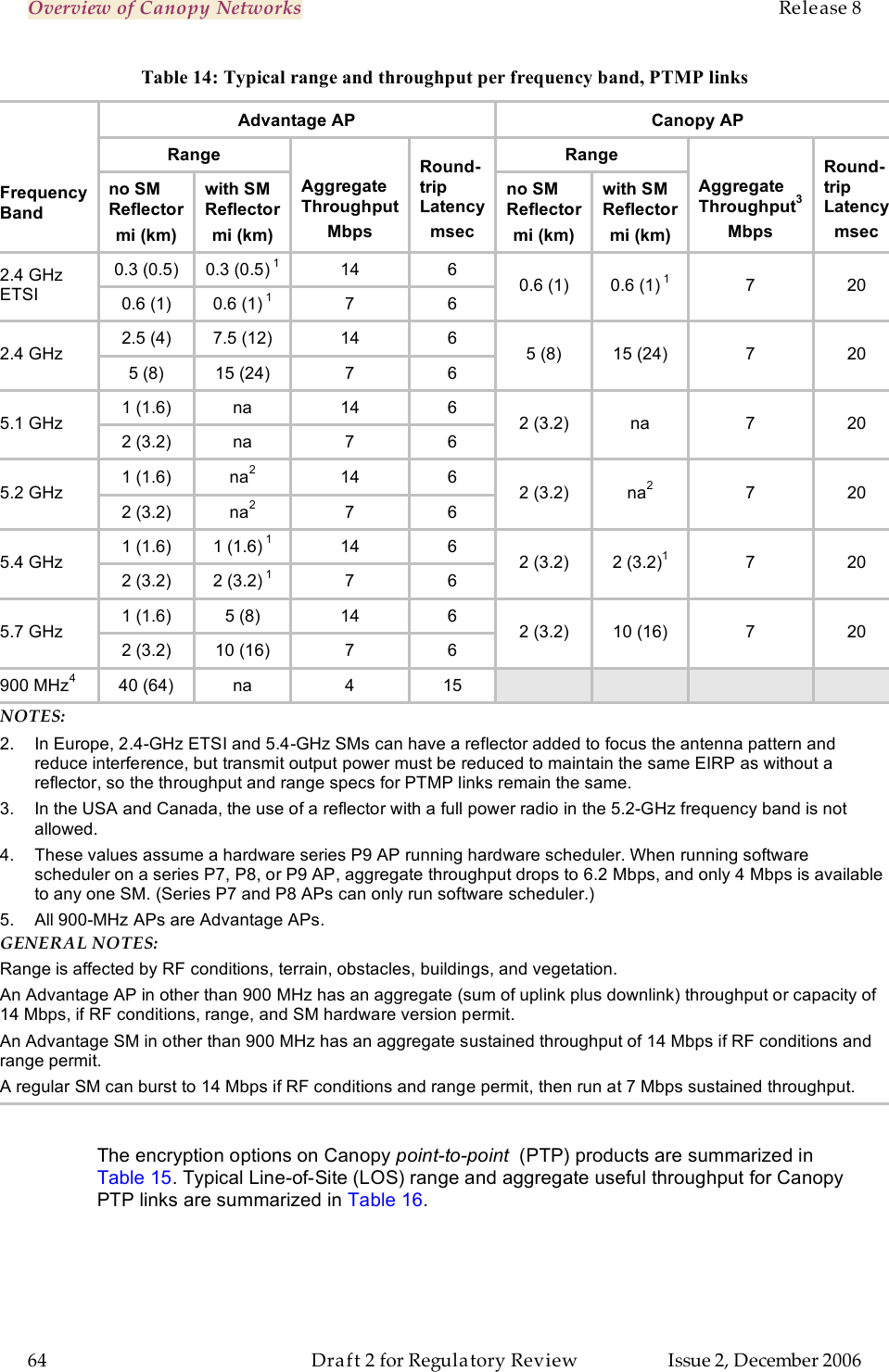
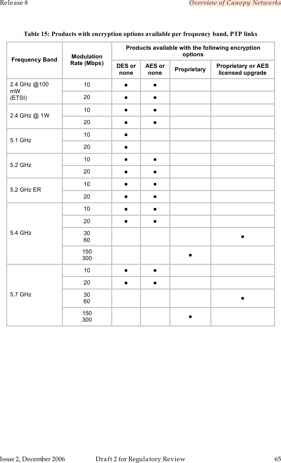
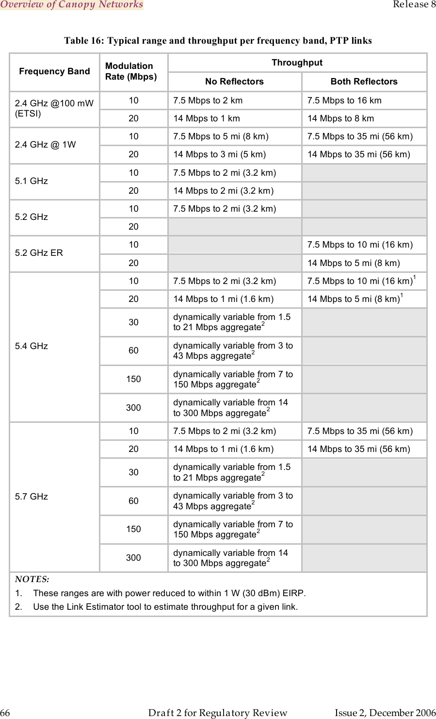
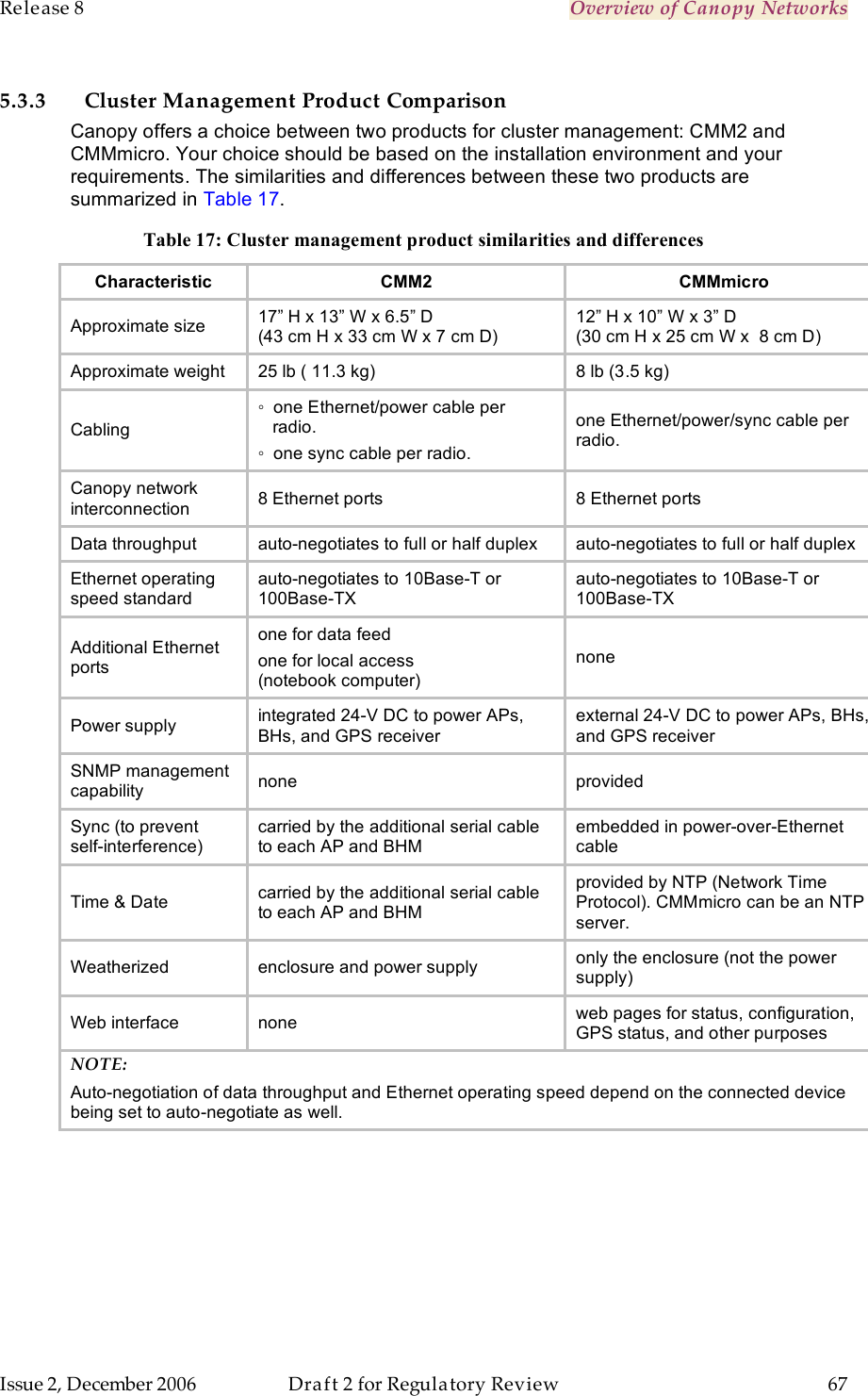
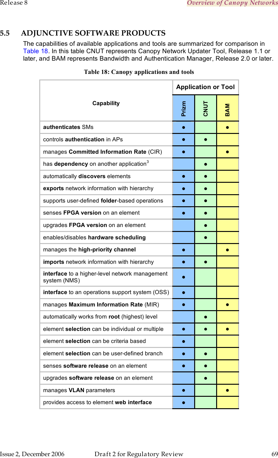
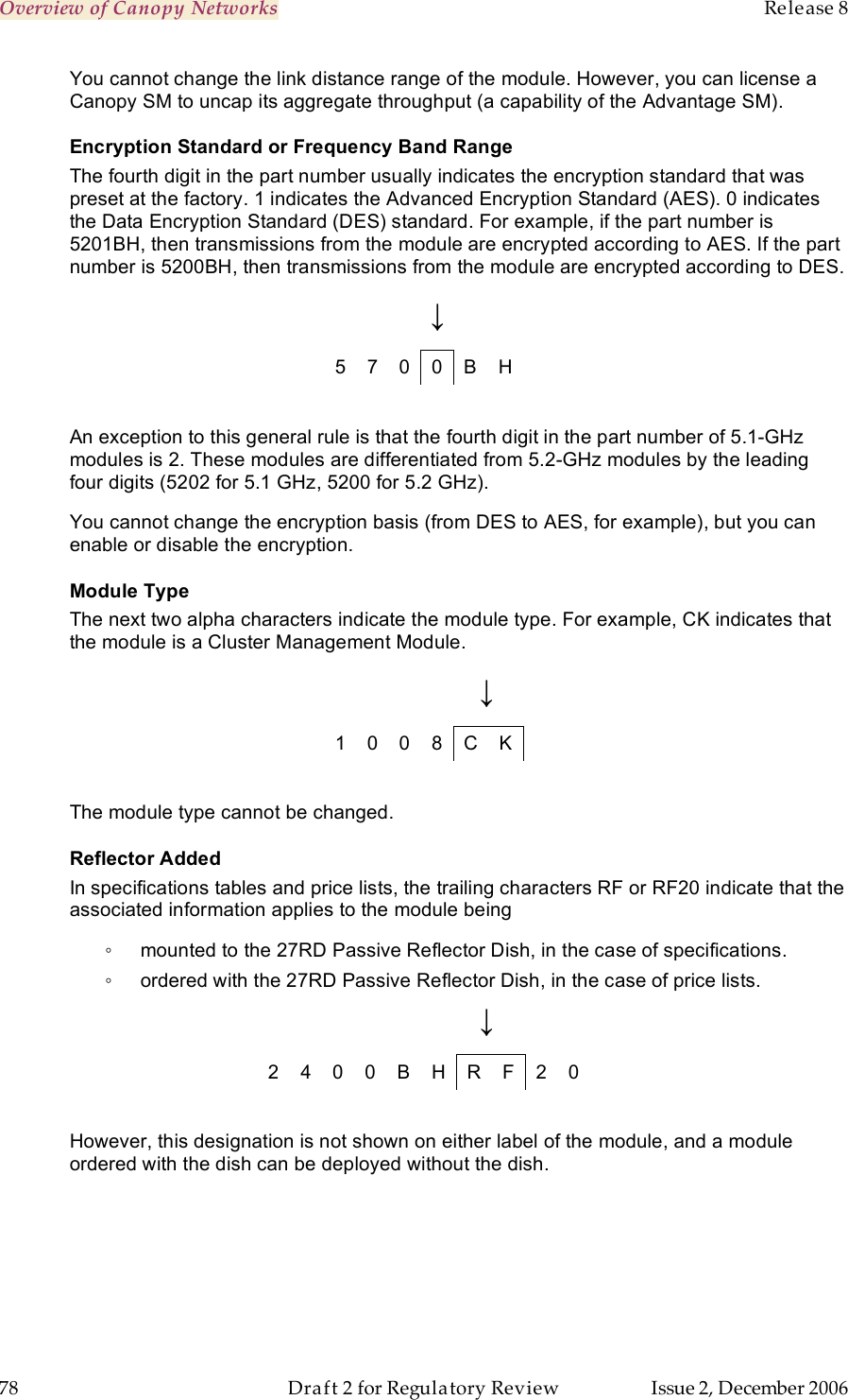
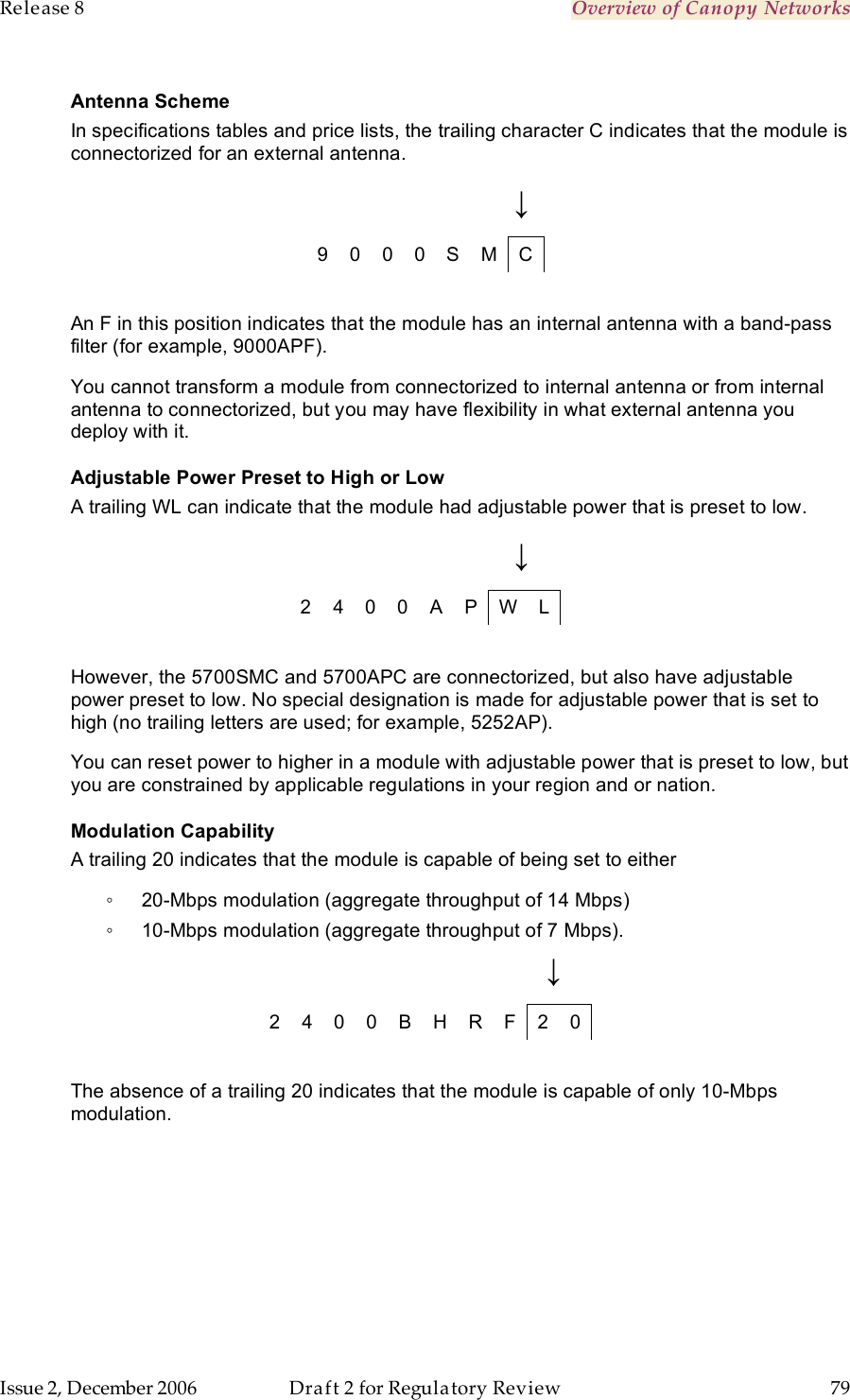
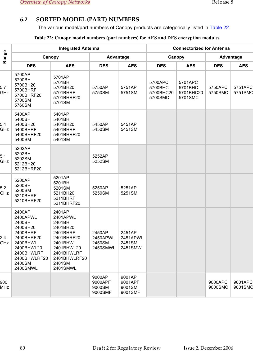
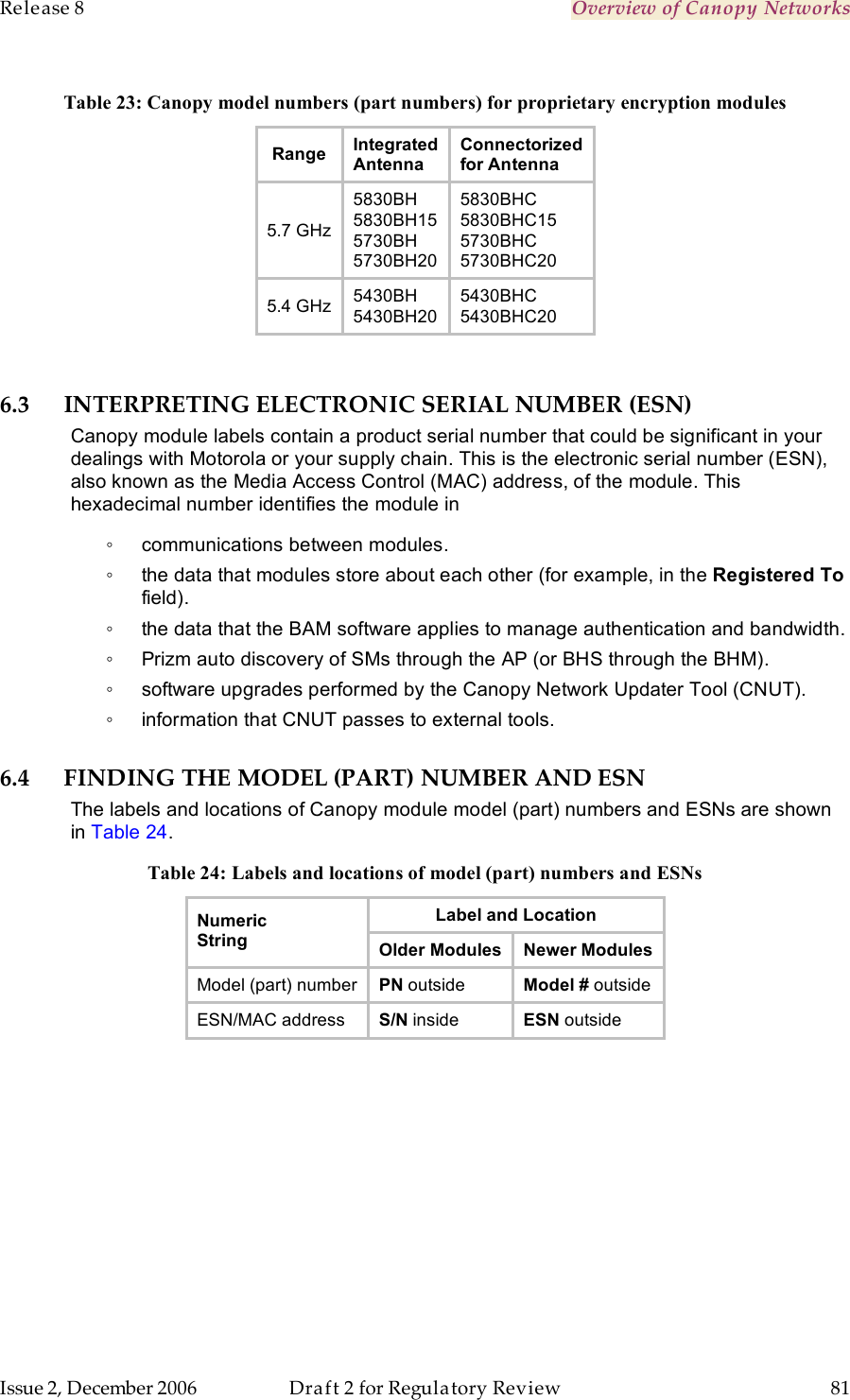
Operations guide pt 1
2.
operations guide pt 2
3.
Operations guide pt 2a
4.
Operations guide pt 3a
5.
Operations guide pt 3b
6.
Operations guide pt 3c
7.
Operations guide pt 3d
8.
Updated Professional install instructions
Operations guide pt 1
Navigation menu
Upload a User Manual
Namespaces
Wiki Guide
HTML
PDF
Info
Views
User Manual
Discussion / Help
Navigation