Motorola Solutions 89FT7623 5400xxyyzzab User Manual Operations guide pt 1
Motorola Solutions, Inc. 5400xxyyzzab Operations guide pt 1
Contents
Operations guide pt 1

March 200 Through Software Release 6.
Draft 3 - for Regulatory Review
Canopy® System
Release 8
User Guide
Sys8-UG-en
Issue 2
February 2007
includes…
Planning Guide
Installation and
Configuration Guide
Operations Guide
Reference
Information
R

Notices
See the following information:
◦ important regulatory and legal notices in Section 36 on Page 489.
◦ personal safety guidelines in Section 15 on Page 169.
Trademarks, Product Names, and Service Names
MOTOROLA, the stylized M Logo and all ot her trademarks indicated as such herein are
trademarks of Motorola, Inc.® Reg. U.S. Pat & Tm. Office. Canopy is a registered
trademark and MOTOwi4 is a trademark of Motorola, Inc. All other product or service
names are the property of their respective owners.
Adobe Reader is a registered trademark of Adobe Systems Incorporated.
Java and all other Java-based marks are trademarks or registered trademarks of Sun
Microsystems, Inc. in the U.S. and other countries.
Microsoft and Windows are registered trademarks of Microsoft Corporation, and Windows
XP is a trademark of Microsoft Corporation.
© 2007 Motorola, Inc. All rights reserved.
http://www.motorola.com/canopy

March 200 Through Software Release 6.
Draft 3 - for Regulatory Review
TABLE OF SECTIONS
Guide To This User Guide
31
Overview of Canopy Networks
43
Planning Guide
127
Installation and Configuration Guide
167
Operations Guide
363
Reference Information
485
Glossary
501
March 200 Through Software Release 6.
Draft 3 - for Regulatory Review
TABLE OF CONTENTS
G
GUIDE
UIDE T
TO
O T
THIS
HIS U
USER
SER G
GUIDE
UIDE .........................
......................... 31
31
1 New in This Issue .................................................................................................... 33
1.1 New Products and Features Described in Issue 2 .......................................... 33
1.2 New Descriptions and Revisions in Issue 2 .................................................... 33
1.3 MOTOwi4 Portfolio......................................................................................... 33
1.4 Products Covered by This User Guide ........................................................... 33
1.5 Products Not Covered by This User Guide..................................................... 34
1.6 Software Compatibility Described in This User Guide..................................... 34
2 Using This User Guide............................................................................................ 35
2.1 Finding the Information You Need .................................................................. 35
2.1.1 Becoming Familiar with This User Guide .......................................................... 35
2.1.2 Searching This User Guide................................................................................. 38
2.1.3 Finding Parameter and Field Definitions for Module Web Pages .................... 38
2.2 Interpreting Typeface and Other Conventions ................................................ 41
2.3 Getting Additional Help................................................................................... 42
2.4 Sending Feedback ......................................................................................... 42
O
OVERVIEW OF
VERVIEW OF C
CANO
ANO P Y
PY N
NETWORKS
ETWORKS ................
................ 43
43
3 Advancing from Research to Implementation ...................................................... 45
4 Realizing a Wireless Backhaul Network ................................................................ 47
5 Exploring the Scope of Solutions .......................................................................... 49
5.1 Components................................................................................................... 49
5.1.1 Canopy Access Point Module............................................................................. 49
5.1.2 Advantage Access Point Module ....................................................................... 49
5.1.3 Access Point Cluster ........................................................................................... 50
5.1.4 Canopy Subscriber Module ................................................................................ 50
5.1.5 Advantage Subscriber Module ........................................................................... 50
5.1.6 Canopy Lite Subscriber Module ......................................................................... 50
5.1.7 900-MHz AP and SM .......................................................................................... 51
5.1.8 Backhaul Module ................................................................................................. 52
5.1.9 OFDM Series Backhaul Modules ....................................................................... 52
5.1.10 Power Indoor Units for OFDM Series Backhaul Modules .............................. 53
5.1.11 Radio Adjustable Power Capabilities ............................................................... 54
5.1.12 T1/E1 Multiplexer............................................................................................... 54
5.1.13 Cluster Management Module-2 (Part 1008CK-2) ........................................... 55
5.1.14 Cluster Management Module micro (Part 1070CK)........................................ 56
5.1.15 GPS Antenna..................................................................................................... 56
5.1.16 Surge Suppressor (Part 300SS)....................................................................... 57
5.1.17 Accessory Components .................................................................................... 57
5.2 Frequency Band Ranges................................................................................ 61
5.3 Canopy Product Comparisons........................................................................ 62
5.3.1 Canopy Product Applications ............................................................................. 62
5.3.2 Link Performance and Encryption Comparisons............................................... 63
5.3.3 Cluster Management Product Comparison ....................................................... 67
5.4 Antennas for Connection to 900-MHz Modules .............................................. 68
5.4.1 Certified Connectorized Flat Panel Antennas ................................................... 68
5.4.2 Third-party Certified Connectorized Flat Panel Antenna .................................. 68
5.5 Adjunctive Software Products......................................................................... 69
5.6 Bandwidth and Authentication Manager ......................................................... 70
5.7 Prizm.............................................................................................................. 70
5.7.1 Network Definition and Element Discovery ....................................................... 70
5.7.2 Monitoring and Fault Management .................................................................... 71
5.7.3 Element Management ......................................................................................... 71
5.7.4 BAM Subsystem in Prizm ................................................................................... 72
5.7.5 Northbound Interface .......................................................................................... 72
5.8 License Management ..................................................................................... 72
5.9 Specifications and Limitations ........................................................................ 74
5.9.1 Radios .................................................................................................................. 74
5.9.2 Cluster Management Products........................................................................... 75
5.9.3 300SS and 600SS Surge Suppressors ............................................................. 76
6 Differentiating Among Components ...................................................................... 77
6.1 Interpreting Model (Part) Number ................................................................... 77
March 200 Through Software Release 6.
Draft 3 - for Regulatory Review
6.2 Sorted Model (Part) Numbers......................................................................... 80
6.3 Interpreting Electronic Serial Number (ESN) .................................................. 81
6.4 Finding the Model (Part) Number and ESN .................................................... 81
7 Canopy Link Characteristics .................................................................................. 83
7.1 Understanding Bandwidth Management......................................................... 83
7.1.1 Downlink Frame Contents .................................................................................. 83
7.1.2 Uplink Frame Contents ....................................................................................... 83
7.1.3 Frame Structure................................................................................................... 84
7.1.4 Media Access Control and AP Capacity ............................................................ 85
7.1.5 Canopy Slot Usage ............................................................................................. 85
7.1.6 Data Transfer Capacity ....................................................................................... 85
7.1.7 Maximum Information Rate (MIR) Parameters ................................................. 85
7.1.8 Committed Information Rate............................................................................... 87
7.1.9 Bandwidth from the SM Perspective.................................................................. 88
7.1.10 Interaction of Burst Allocation and Sustained Data Rate Settings................. 88
7.1.11 High-priority Bandwidth..................................................................................... 88
7.1.12 Hardware Scheduling ........................................................................................ 90
7.1.13 2X Operation...................................................................................................... 91
7.2 Understanding Synchronization...................................................................... 94
7.2.1 GPS Synchronization .......................................................................................... 94
7.2.2 Passing Sync in a Single Hop ............................................................................ 96
7.2.3 Passing Sync in an Additional Hop .................................................................... 97
8 Meeting Link Requirements ................................................................................... 99
8.1 AP-SM Links .................................................................................................. 99
8.2 BH-BH Links................................................................................................. 100
9 Previewing Network Configurations .................................................................... 103
9.1 Viewing Typical Layouts............................................................................... 103
9.2 Viewing Case Studies .................................................................................. 105
10 Accessing Features ............................................................................................ 107
10.1 Activating Features..................................................................................... 114
10.1.1 Fixed License Keys ......................................................................................... 114
10.2 Enabling Features ...................................................................................... 115
11 Acquiring Proficiencies ...................................................................................... 117
11.1 Understanding RF Fundamentals ............................................................... 117
11.2 Understanding IP Fundamentals................................................................. 117
11.3 Acquiring a Canopy Demonstration Kit ....................................................... 117
11.3.1 900-MHz with Integrated Antenna and Band-pass Filter Demonstration Kit117
11.3.2 900-MHz with Connectorized Antenna Demonstration Kit ........................... 117
11.3.3 2.4-GHz with Adjustable Power Set to Low Demonstration Kit .................. 118
11.3.4 2.4-GHz with Adjustable Power Set to High Demonstration Kit................... 118
11.3.5 5.1-GHz Demonstration Kit............................................................................. 119
11.3.6 5.2-GHz Demonstration Kit............................................................................. 119
11.3.7 5.4-GHz Demonstration Kit............................................................................. 119
11.3.8 5.7-GHz with Integrated Antenna Demonstration Kit.................................... 120
11.3.9 5.7-GHz with Connectorized Antenna and Adjustable Power Set to Low...120
11.3.10 Demonstration Kit Part Numbers ................................................................... 120
11.4 Acquiring a Canopy Starter Kit.................................................................... 121
11.4.1 900-MHz with Integrated Antenna and Band-pass Filter Starter Kit............ 121
11.4.2 900-MHz with Connectorized Antenna Starter Kit ........................................ 122
11.4.3 2.4-GHz with Adjustable Power Set to Low Starter Kit................................. 122
11.4.4 2.4-GHz with Adjustable Power Set to High Starter Kit................................ 122
11.4.5 5.1-GHz Starter Kit .......................................................................................... 123
11.4.6 5.2-GHz Starter Kit .......................................................................................... 123
11.4.7 5.4-GHz Starter Kit .......................................................................................... 123
11.4.8 5.7-GHz with Integrated Antenna Starter Kit.................................................124
11.4.9 5.7-GHz with Connectorized Antenna and Adjustable Power Set to Low...124
11.4.10 Starter Kit Part Numbers.................................................................................124
11.5 Evaluating Canopy Training Options........................................................... 125
11.6 Attending On-line Knowledge Sessions ...................................................... 125
P
PLANNING
LANNING G
GUIDE
UIDE ................................
........................................
........127
127
12 Engineering Your RF Communications ............................................................. 129
12.1 Anticipating RF Signal Loss........................................................................ 129
12.1.1 Understanding Attenuation .............................................................................129
12.1.2 Calculating Free Space Path Loss................................................................. 129
12.1.3 Calculating Rx Signal Level ............................................................................129
12.1.4 Calculating Fade Margin ................................................................................. 130
March 200 Through Software Release 6.
Draft 3 - for Regulatory Review
12.2 Analyzing the RF Environment ................................................................... 131
12.2.1 Mapping RF Neighbor Frequencies ............................................................... 131
12.2.2 Anticipating Reflection of Radio Waves......................................................... 132
12.2.3 Noting Possible Obstructions in the Fresnel Zone........................................ 132
12.2.4 Radar Signature Detection and Shutdown (Dynamic Frequency Selection –
DFS) ................................................................................................................. 132
12.3 Using Jitter to Check Received Signal Quality ............................................ 134
12.4 Using Link Efficiency to Check Received Signal Quality ............................. 135
12.4.1 Comparing Efficiency in 1X Operation to Efficiency in 2X Operation .......... 135
12.4.2 When to Switch from 2X to 1X Operation Based on 60% Link Efficiency... 135
12.5 Considering Frequency Band Alternatives .................................................. 136
12.5.1 900-MHz Channels.......................................................................................... 137
12.5.2 2.4-GHz Channels........................................................................................... 137
12.5.3 5.2-GHz Channels........................................................................................... 137
12.5.4 5.4-GHz Channels........................................................................................... 138
12.5.5 5.7-GHz Channels........................................................................................... 139
12.5.6 Channels Available for OFDM Backhaul Modules........................................ 140
12.5.7 Example Channel Plans for AP Clusters ....................................................... 140
12.5.8 Multiple Access Points Clusters ..................................................................... 141
12.6 Selecting Sites for Network Elements ......................................................... 142
12.6.1 Resources for Maps and Topographic Images .............................................143
12.6.2 Surveying Sites................................................................................................ 143
12.6.3 Assuring the Essentials...................................................................................144
12.6.4 Finding the Expected Coverage Area ............................................................ 144
12.6.5 Clearing the Radio Horizon............................................................................. 145
12.6.6 Calculating the Aim Angles............................................................................. 145
12.7 Collocating Canopy Modules ...................................................................... 146
12.8 Deploying a Remote AP ............................................................................. 147
12.8.1 Remote AP Performance ................................................................................ 148
12.8.2 Example Use Case for RF Obstructions........................................................148
12.8.3 Example Use Case for Passing Sync ............................................................ 149
12.8.4 Physical Connections Involving the Remote AP ...........................................150
12.9 Diagramming Network Layouts................................................................... 151
12.9.1 Accounting for Link Ranges and Data Handling Requirements................... 151
12.9.2 Avoiding Self Interference............................................................................... 151
12.9.3 Avoiding Other Interference............................................................................ 153
13 Engineering Your IP Communications .............................................................. 155
13.1 Understanding Addresses........................................................................... 155
13.1.1 IP Address ....................................................................................................... 155
13.2 Dynamic or Static Addressing..................................................................... 155
13.2.1 When a DHCP Server is Not Found .............................................................. 155
13.3 Network Address Translation (NAT) ........................................................... 156
13.3.1 NAT, DHCP Server, DHCP Client, and DMZ in SM ..................................... 156
13.3.2 NAT and VPNs ................................................................................................ 161
13.4 Developing an IP Addressing Scheme........................................................ 161
13.4.1 Address Resolution Protocol ..........................................................................162
13.4.2 Allocating Subnets........................................................................................... 162
13.4.3 Selecting Non-routable IP Addresses ............................................................ 162
14 Engineering VLANs............................................................................................. 165
14.1 SM Membership in VLANs.......................................................................... 165
14.2 Priority on VLANs (802.1p) ......................................................................... 166
I
INS TALLATION AND
NS TALLATION AND C
CONFIGURATION
ONFIGURATION G
GUIDE
UIDE 167
167
15 Avoiding Hazards ................................................................................................ 169
15.1 Preventing Overexposure to RF Energy ..................................................... 169
15.1.1 Details of Calculations for Separation Distances and Power Compliance
Margins............................................................................................................. 169
15.2 Grounding Canopy Equipment.................................................................... 171
15.2.1 Grounding Infrastructure Equipment..............................................................171
15.2.2 Grounding Canopy 30/60- and 150/300-Mbps Backhaul Modules.............. 172
15.2.3 Grounding SMs................................................................................................ 172
15.3 Conforming to Regulations ......................................................................... 174
15.4 Protecting Cables and Connections............................................................ 174
16 Testing the Components .................................................................................... 177
16.1 Unpacking Components ............................................................................. 177
16.2 Configuring for Test .................................................................................... 177
16.2.1 Configuring the Computing Device for Test .................................................. 177
16.2.2 Default Module Configuration ......................................................................... 178
16.2.3 Component Layout .......................................................................................... 178
March 200 Through Software Release 6.
Draft 3 - for Regulatory Review
16.2.4 Diagnostic LEDs ..............................................................................................179
16.2.5 CMM2 Component Layout.............................................................................. 180
16.2.6 CMMmicro Component Layout....................................................................... 180
16.2.7 Standards for Wiring .......................................................................................182
16.2.8 Best Practices for Cabling .............................................................................. 182
16.2.9 Recommended Tools for Wiring Connectors ................................................182
16.2.10 Wiring Connectors ........................................................................................... 182
16.2.11 Alignment Tone—Technical Details ............................................................... 184
16.3 Configuring a Point-to-Multipoint Link for Test ............................................ 184
16.3.1 Quick Start Page of the AP............................................................................. 185
16.3.2 Time Tab of the AP .........................................................................................191
16.3.3 Session Status Tab of the AP......................................................................... 193
16.3.4 Beginning the Test of Point-to-Multipoint Links............................................. 197
16.3.5 Remote Subscribers Tab of the AP ............................................................... 197
16.3.6 General Status Tab of the SM ........................................................................ 198
16.3.7 Continuing the Test of Point-to-Multipoint Links ........................................... 200
16.3.8 General Status Tab of the AP......................................................................... 201
16.3.9 Concluding the Test of Point-to-Multipoint Links........................................... 203
16.4 Configuring a Point-to-Point Link for Test ................................................... 204
16.4.1 Quick Start Page of the BHM ......................................................................... 205
16.4.2 Time Tab of the BHM ...................................................................................... 206
16.4.3 Beginning the Test of Point-to-Point Links .................................................... 210
16.4.4 Continuing the Test of Point-to-Point Links ................................................... 212
16.4.5 General Status Tab of the BHM ..................................................................... 213
16.4.6 Concluding the Test of Point-to-Point Links .................................................. 215
16.4.7 Setting up a CMMmicro ..................................................................................216
16.4.8 Status Page of the CMMmicro ....................................................................... 221
16.4.9 Configuration Page of the CMMmicro............................................................224
16.4.10 Configuring Modules for Connection to CMMmicro ...................................... 231
16.4.11 Event Log Page of the CMMmicro ................................................................. 231
16.4.12 GPS Status Page of the CMMmicro .............................................................. 231
16.4.13 Port MIB Page of the CMMmicro ................................................................... 232
17 Preparing Components for Deployment............................................................ 233
17.1 Correlating Component-specific Information ............................................... 233
17.2 Ensuring Continuing Access to the Modules............................................... 233
18 Configuring for the Destination.......................................................................... 235
18.1 Configuring an AP for the Destination......................................................... 235
18.1.1 General Tab of the AP ....................................................................................235
18.1.2 IP Tab of the AP .............................................................................................. 239
18.1.3 Radio Tab of the AP........................................................................................ 241
18.1.4 SNMP Tab of the AP....................................................................................... 246
18.1.5 Quality of Service (QoS) Tab of the AP ......................................................... 249
18.1.6 Security Tab of the AP .................................................................................... 251
18.1.7 VLAN Tab of the AP........................................................................................ 253
18.1.8 VLAN Membership Tab of the AP .................................................................. 255
18.1.9 DiffServe Tab of the AP .................................................................................. 256
18.1.10 Unit Settings Tab of the AP ............................................................................ 258
18.2 Configuring an SM for the Destination ........................................................ 259
18.2.1 General Tab of the SM.................................................................................... 260
18.2.2 NAT and IP Tabs of the SM with NAT Disabled ........................................... 262
18.2.3 NAT and IP Tabs of the SM with NAT Enabled ............................................ 268
18.2.4 Radio Tab of the SM .......................................................................................273
18.2.5 SNMP Tab of the SM ...................................................................................... 276
18.2.6 Quality of Service (QoS) Tab of the SM ........................................................279
18.2.7 Security Tab of the SM ................................................................................... 282
18.2.8 VLAN Tab of the SM .......................................................................................284
18.2.9 VLAN Membership Tab of the SM ................................................................. 286
18.2.10 DiffServe Tab of the SM..................................................................................287
18.2.11 Protocol Filtering Tab of the SM..................................................................... 289
18.2.12 NAT Port Mapping Tab of the SM .................................................................. 290
18.2.13 Unit Settings Tab of the SM............................................................................ 291
18.3 Setting the Configuration Source ................................................................ 292
18.4 Configuring a BH Timing Master for the Destination ................................... 294
18.4.1 General Tab of the BHM ................................................................................. 295
18.4.2 IP Tab of the BHM........................................................................................... 298
18.4.3 Radio Tab of the BHM.....................................................................................300
18.4.4 SNMP Tab of the BHM ...................................................................................303
18.4.5 Security Tab of the BHM................................................................................. 306
18.4.6 DiffServe Tab of the BHM............................................................................... 308
18.4.7 Unit Settings Tab of the BHM ......................................................................... 310
March 200 Through Software Release 6.
Draft 3 - for Regulatory Review
18.5 Configuring a BH Timing Slave for the Destination ..................................... 312
18.5.1 General Tab of the BHS.................................................................................. 312
18.5.2 IP Tab of the BHS ........................................................................................... 315
18.5.3 Radio Tab of the BHS ..................................................................................... 316
18.5.4 SNMP Tab of the BHS .................................................................................... 319
18.5.5 Quality of Service (QoS) Tab of the BHS ...................................................... 321
18.5.6 Security Tab of the BHS ................................................................................. 322
18.5.7 DiffServe Tab of the BHS ............................................................................... 324
18.5.8 Unit Settings Tab of the BHS.......................................................................... 325
18.6 Adjusting Transmitter Output Power ........................................................... 326
19 Installing Components........................................................................................ 331
19.1 PDA Access to Canopy Modules ................................................................ 331
19.2 Installing an AP........................................................................................... 334
19.3 Installing a Connectorized Flat Panel Antenna............................................ 335
19.4 Installing a GPS Antenna............................................................................ 336
19.4.1 Recommended Materials for Cabling the GPS Antenna .............................. 337
19.4.2 Cabling the GPS Antenna............................................................................... 337
19.5 Installing a CMM2 ....................................................................................... 337
19.5.1 CMM2 Installation Temperature Range.........................................................337
19.5.2 Recommended Tools for Mounting a CMM2 ................................................ 337
19.5.3 Mounting a CMM2 ........................................................................................... 338
19.5.4 Cabling a CMM2.............................................................................................. 338
19.5.5 Verifying CMM2 Connections .........................................................................342
19.6 Installing a CMMmicro ................................................................................ 342
19.6.1 CMMmicro Temperature Range..................................................................... 343
19.6.2 Recommended Tools for Mounting a CMMmicro ......................................... 343
19.6.3 Mounting a CMMmicro.................................................................................... 343
19.6.4 Installing the Power Supply for the CMMmicro .............................................343
19.6.5 Cabling a CMMmicro.......................................................................................344
19.6.6 Verifying CMMmicro Connections.................................................................. 345
19.7 Installing an SM .......................................................................................... 346
19.8 Verifying an AP-SM Link............................................................................. 349
19.9 Installing a Reflector Dish ........................................................................... 352
19.9.1 Both Modules Mounted at Same Elevation ................................................... 352
19.9.2 Modules Mounted at Different Elevations...................................................... 353
19.9.3 Mounting Assembly ......................................................................................... 353
19.10 Installing a BH Timing Master ..................................................................... 354
19.11 Installing a BH Timing Slave ....................................................................... 356
19.12 Upgrading a BH Link to BH20..................................................................... 357
19.13 Verifying a BH Link ..................................................................................... 357
20 Verifying System Functionality .......................................................................... 361
O
OPERATIONS
PERATIONS G
GUIDE
UIDE ................................
.....................................
.....363
363
21 Growing Your Network ....................................................................................... 365
21.1 Monitoring the RF Environment .................................................................. 365
21.1.1 Spectrum Analyzer ..........................................................................................365
21.1.2 Graphical Spectrum Analyzer Display ........................................................... 365
21.1.3 Using the AP as a Spectrum Analyzer...........................................................366
21.2 Considering Software Release Compatibility .............................................. 367
21.2.1 Designations for Hardware in Radios ............................................................ 367
21.2.2 CMMmicro Software and Hardware Compatibility ........................................368
21.2.3 MIB File Set Compatibility............................................................................... 368
21.3 Redeploying Modules ................................................................................. 369
21.3.1 Wiring to Extend Network Sync ...................................................................... 369
22 Securing Your Network....................................................................................... 371
22.1 Isolating APs from the Internet.................................................................... 371
22.2 Encrypting Canopy Radio Transmissions ................................................... 371
22.2.1 DES Encryption ............................................................................................... 371
22.2.2 AES Encryption ............................................................................................... 371
22.2.3 AES-DES Operability Comparisons ............................................................... 372
22.3 Managing Module Access by Passwords.................................................... 373
22.3.1 Adding a User for Access to a Module ..........................................................373
22.3.2 Overriding Forgotten IP Addresses or Passwords on AP, SM, or BH......... 375
22.3.3 Overriding Forgotten IP Addresses or Passwords on CMMmicro ............... 377
22.4 Requiring SM Authentication ...................................................................... 377
22.5 Filtering Protocols and Ports....................................................................... 378
22.5.1 Port Filtering with NAT Enabled ..................................................................... 378
22.5.2 Protocol and Port Filtering with NAT Disabled .............................................. 378
March 200 Through Software Release 6.
Draft 3 - for Regulatory Review
22.6 Encrypting Downlink Broadcasts................................................................. 380
22.7 Isolating SMs.............................................................................................. 380
22.8 Filtering Management through Ethernet...................................................... 381
22.9 Allowing Management from Only Specified IP Addresses........................... 381
22.10 Configuring Management IP by DHCP........................................................ 381
23 Managing Bandwidth and Authentication ......................................................... 383
23.1 Managing Bandwidth without BAM ............................................................. 383
23.2 Bandwidth and Authentication Manager (BAM) Services and Features ...... 383
23.2.1 Bandwidth Manager Capability....................................................................... 383
23.2.2 Authentication Manager Capability ................................................................ 385
24 Managing the Network From a Management Station (NMS) ............................ 387
24.1 Roles of Hardware and Software Elements ................................................ 387
24.1.1 Role of the Agent............................................................................................. 387
24.1.2 Role of the Managed Device .......................................................................... 387
24.1.3 Role of the NMS .............................................................................................. 387
24.1.4 Dual Roles for the NMS .................................................................................. 387
24.1.5 Simple Network Management Protocol (SNMP) Commands ...................... 387
24.1.6 Traps from the Agent ......................................................................................388
24.1.7 AP SNMP Proxy to SMs .................................................................................388
24.2 Management Information Base (MIB) ......................................................... 388
24.2.1 Cascading Path to the MIB.............................................................................388
24.2.2 Object Instances.............................................................................................. 389
24.2.3 Management Information Base Systems and Interface (MIB-II).................. 389
24.2.4 Canopy Enterprise MIB................................................................................... 390
24.3 Configuring Modules for SNMP Access ...................................................... 391
24.4 Objects Defined in the Canopy Enterprise MIB ........................................... 391
24.4.1 AP, SM, and BH Objects................................................................................. 391
24.4.2 AP and BH Timing Master Objects ................................................................ 394
24.4.3 SM and BH Timing Slave Objects.................................................................. 398
24.4.4 CMMmicro Objects.......................................................................................... 401
24.5 Objects Defined in the Canopy OFDM BH Module MIB .............................. 404
24.6 Objects Supported in the Canopy 30/60-Mbps BH...................................... 405
24.7 Objects Supported in the Canopy 150/300-Mbps BH.................................. 405
24.8 Interface Designations in SNMP ................................................................. 405
24.9 Traps Provided in the Canopy Enterprise MIB ............................................ 406
24.10 Traps Provided in the Canopy 30/60-Mbps BH Module MIB ....................... 406
24.11 Traps Provided in the Canopy 150/300-Mbps BH Module MIB ................... 406
24.12 MIB Viewers ............................................................................................... 407
25 Using the Canopy Network Updater Tool (CNUT) ............................................. 409
25.1 CNUT Functions ......................................................................................... 409
25.2 Network Element Groups............................................................................ 409
25.3 Network Layers........................................................................................... 409
25.4 Script Engine .............................................................................................. 410
25.5 Software Dependencies for CNUT.............................................................. 410
25.6 CNUT Download......................................................................................... 410
26 Using Informational Tabs in the GUI.................................................................. 411
26.1 Viewing General Status (All) ....................................................................... 411
26.2 Viewing Session Status (AP, BHM) ............................................................ 411
26.3 Viewing Remote Subscribers (AP, BHM) .................................................... 412
26.4 Interpreting Messages in the Event Log (All) .............................................. 412
26.4.1 Time and Date Stamp ..................................................................................... 412
26.4.2 Event Log Data Collection .............................................................................. 412
26.4.3 Messages that Flag Abnormal Events ........................................................... 414
26.4.4 Messages that Flag Normal Events ............................................................... 414
26.5 Viewing the Network Interface Tab (All) ...................................................... 415
26.6 Interpreting Radio Statistics in the Scheduler Tab (All) ............................... 416
26.7 Viewing the List of Registration Failures (AP, BHM) ................................... 417
26.8 Interpreting Data in the Bridging Table (All) ................................................ 418
26.9 Translation Table (SM) ............................................................................... 419
26.10 Interpreting Data in the Ethernet Tab (All)................................................... 419
26.11 Interpreting RF Control Block Statistics in the Radio Tab (All) .................... 422
26.12 Interpreting Data in the VLAN Tab (AP, SM)............................................... 423
26.13 Data VC (All)............................................................................................... 425
26.14 Filter (SM)................................................................................................... 426
26.15 NAT Stats (SM) .......................................................................................... 427
26.15.1 NAT DHCP Statistics (SM) ............................................................................. 428
26.15.2 Interpreting Data in the GPS Status Page (AP, BHM).................................. 429
March 200 Through Software Release 6.
Draft 3 - for Regulatory Review
27 Using Tools in the GUI ........................................................................................ 431
27.1 Using the Spectrum Analyzer Tool (SM, BHS)............................................ 431
27.2 Using the Alignment Tool (SM, BHS).......................................................... 431
27.3 Using the Link Capacity Test Tool (All) ....................................................... 434
27.4 Using the AP Evaluation or BHM Evaluation Tool (SM, BHS) ..................... 436
27.5 Using the Frame Calculator Tool (All) ......................................................... 440
27.6 Using the SM Configuration Tool (AP, BHM) .............................................. 445
27.7 Using the BER Results Tool (SM, BHS)...................................................... 446
28 Maintaining Your Canopy Software ................................................................... 447
28.1 History of System Software Upgrades ........................................................ 447
28.1.1 Canopy Release 8.1 Features........................................................................ 447
28.1.2 Canopy Release 8.1 Fixes.............................................................................. 447
28.2 History of CMMmicro Software Upgrades ................................................... 447
28.3 Typical Contents of Release Notes............................................................. 447
28.4 Typical Upgrade Process............................................................................ 447
28.4.1 Downloading Software and Release Notes................................................... 448
29 Rebranding Module Interface Screens .............................................................. 449
30 Toggling Remote Access Capability.................................................................. 453
30.1 Denying All Remote Access........................................................................ 453
30.2 Reinstating Remote Access Capability ....................................................... 453
31 Setting Up a Protocol Analyzer on Your Canopy Network ............................... 455
31.1 Analyzing Traffic at an SM .......................................................................... 455
31.2 Analyzing Traffic at an AP or BH with No CMM .......................................... 456
31.3 Analyzing Traffic at an AP or BH with a CMM ............................................. 456
31.4 Example of a Protocol Analyzer Setup for an SM ....................................... 457
32 Troubleshooting.................................................................................................. 465
32.1 General Planning for Troubleshooting ........................................................ 465
32.2 General Fault Isolation Process.................................................................. 465
32.3 Questions to Help Isolate the Problem........................................................ 466
32.4 Secondary Steps ........................................................................................ 466
32.5 Procedures for Troubleshooting.................................................................. 467
32.5.1 Module Has Lost or Does Not Establish Connectivity .................................. 467

32.5.2 NAT/DHCP-configured SM Has Lost or Does Not Establish Connectivity.. 468
32.5.3 SM Does Not Register to an AP..................................................................... 470
32.5.4 BHS Does Not Register to the BHM .............................................................. 471
32.5.5 Module Has Lost or Does Not Gain Sync...................................................... 472
32.5.6 Module Does Not Establish Ethernet Connectivity ....................................... 473
32.5.7 Module Does Not Power Up ........................................................................... 474
32.5.8 Power Supply Does Not Produce Power ....................................................... 474
32.5.9 CMM2 Does Not Power Up ............................................................................ 475
32.5.10 CMM2 Does Not Pass Proper GPS Sync to Connected Modules............... 475
32.5.11 Module Software Cannot be Upgraded ......................................................... 476
32.5.12 Module Functions Properly, Except Web Interface Became Inaccessible.. 476
33 Obtaining Technical Support ............................................................................. 477
34 Getting Warranty Assistance ............................................................................. 483
R
REFERENCE
EFERENCE I
INFORMATION
NFORMATION ............................
............................485
485
35 Administering Modules through telnet Interface .............................................. 487
36 Legal and Regulatory Notices ............................................................................ 489
36.1 Important Note on Modifications ................................................................. 489
36.2 National and Regional Regulatory Notices.................................................. 489
36.2.1 U.S. Federal Communication Commission (FCC) and Industry Canada (IC)
Notification ....................................................................................................... 489
36.2.2 Regulatory Requirements for CEPT Member States (http://www.cept.org) 490
36.2.3 European Union Notification ...........................................................................491
36.2.4 UK Notification ................................................................................................. 492
36.2.5 Belgium Notification.........................................................................................492
36.2.6 Luxembourg Notification .................................................................................492
36.2.7 Czech Republic Notification............................................................................ 492
36.2.8 Norway Notification ......................................................................................... 492
36.2.9 Greece Notification..........................................................................................493
36.2.10 Brazil Notification............................................................................................. 493
36.2.11 Australia Notification ....................................................................................... 493
36.3 Exposure .................................................................................................... 493
36.4 Equipment Disposal.................................................................................... 494
March 200 Through Software Release 6.
Draft 3 - for Regulatory Review
36.5 Legal Notices.............................................................................................. 494
36.5.1 Software License Terms and Conditions ....................................................... 494
36.5.2 Hardware Warranty in U.S.............................................................................. 496
36.5.3 Limit of Liability ................................................................................................496
37 Additional Resources ......................................................................................... 497
38 History of Documentation................................................................................... 499
G
GLOSSARY
LOSSARY ................................
...................................................
...................501
501
LIST OF FIGURES
Figure 1: Canopy Advantage Platform GUI logo.............................................................. 49
Figure 2: Pole-mounted AP cluster.................................................................................. 50
Figure 3: Structure-mounted SM ..................................................................................... 50
Figure 4: Examples of flat panel antennas with 900-MHz modules.................................. 51
Figure 5: Dish-mounted 10- or 20-Mbps BH .................................................................... 52
Figure 6: 30/60- or 150/300-Mbps Backhaul Module, integrated antenna........................ 52
Figure 7: 30/60- or 150/300-Mbps Backhaul Module, connected to external antenna..... 53
Figure 8: PIDU for 30/60-Mbps BH.................................................................................. 53
Figure 9: PIDU for 150/300-Mbps BH.............................................................................. 53
Figure 10: T1/E1 Multiplexer, front view .......................................................................... 54
Figure 11: T1/E1 Multiplexer, rear view ........................................................................... 54
Figure 12: CMM2 enclosure ............................................................................................ 55
Figure 13: CMM2 pole-mounted...................................................................................... 55
Figure 14: Motorola GPS antenna................................................................................... 56
Figure 15: 300SS surge suppressor................................................................................ 57
Figure 16: ACPS110-03A power supply .......................................................................... 58
Figure 17: ACPSSW-09A power supply .......................................................................... 58
Figure 18: 27RD with mounted module ........................................................................... 58
Figure 19: SMMB1 SM support bracket........................................................................... 59
Figure 20: ACATHS-01 alignment headset...................................................................... 61
Figure 21: HSG-01 Housing ............................................................................................ 61
Figure 22: Uplink data slot usage .................................................................................... 85
Figure 23: TDD dividing Canopy frames.......................................................................... 85
Figure 24: Uplink and downlink rate caps adjusted to apply aggregate cap..................... 87
Figure 25: Uplink and downlink rate cap adjustment example ......................................... 87
Figure 26: Canopy channel, 75% downlink, 0% high priority in uplink ............................. 90
Figure 27: One unsynchronized AP in cluster.................................................................. 95
Figure 28: GPS timing throughout the Canopy network................................................... 96
Figure 29: Additional link to extend network sync, Design 3 ............................................ 97
Figure 30: Additional link to extend network sync, Design 4 ............................................ 98
Figure 31: Additional link to extend network sync, Design 5 ............................................ 98
March 200 Through Software Release 6.
Draft 3 - for Regulatory Review
Figure 32: Canopy Path Profiler tool ............................................................................. 101
Figure 33: OFDM series BH Link Estimator tool ............................................................ 102
Figure 34: Typical network layout with no BH................................................................ 103
Figure 35: Typical network layout with BH..................................................................... 104
Figure 36: Typical multiple-BH network layout............................................................... 104
Figure 37: Determinants in Rx signal level .................................................................... 130
Figure 38: Example layout of 7 Access Point clusters ................................................... 142
Figure 39: Fresnel zone ................................................................................................ 144
Figure 40: Variables for calculating angle of elevation (and depression) ....................... 145
Figure 41: Double-hop backhaul links ........................................................................... 146
Figure 42: Remote AP deployment ............................................................................... 147
Figure 43: Example 900-MHz remote AP behind 2.4-GHz SM ...................................... 149
Figure 44: Remote AP wired to SM that also serves a customer ................................... 150
Figure 45: Remote AP wired to SM that serves as a relay............................................. 151
Figure 46: NAT Disabled implementation ...................................................................... 157
Figure 47: NAT with DHCP Client and DHCP Server implementation ........................... 158
Figure 48: NAT with DHCP Client implementation......................................................... 159
Figure 49: NAT with DHCP Server implementation ....................................................... 160
Figure 50: NAT without DHCP implementation.............................................................. 161
Figure 51: Example of IP address in Class B subnet..................................................... 162
Figure 52: Canopy base cover, attached and detached................................................. 178
Figure 53: Canopy CMM2, bottom view ........................................................................ 180
Figure 54: Cluster Management Module micro.............................................................. 181
Figure 55: RJ-45 pinout for straight-through Ethernet cable .......................................... 183
Figure 56: RJ-45 pinout for crossover Ethernet cable.................................................... 183
Figure 57: RJ-11 pinout for straight-through sync cable ................................................ 184
Figure 58: Quick Start tab of AP, example .................................................................... 186
Figure 59: Radio Frequency Carrier tab of AP, example ............................................... 187
Figure 60: Synchronization tab of AP, example............................................................. 188
Figure 61: LAN IP Address tab of AP, example............................................................. 189
Figure 62: Review and Save Configuration tab of AP, example..................................... 190
Figure 63: Time tab of AP, example .............................................................................. 191
Figure 64: Session Status tab data from AP, example .................................................. 193
Figure 65: Remote Subscribers tab of AP, example ...................................................... 197
Figure 66: General Status tab of SM, example.............................................................. 198
Figure 67: General Status tab of AP, example .............................................................. 201
Figure 68: Quick Start tab of BHM, example ................................................................. 205
Figure 69: Time tab of BHM, example ........................................................................... 207
Figure 70: Remote Subscribers tab of BHM, example................................................... 209
Figure 71: General Status tab of BHS, example............................................................ 210
Figure 72: General Status tab of BHM, example ........................................................... 213
Figure 73: CMMmicro layout ......................................................................................... 216
Figure 74: CMMmicro door label ................................................................................... 218
Figure 75: CMMmicro circuit board ............................................................................... 220
Figure 76: CMMmicro connections................................................................................ 220
Figure 77: Status page of CMMmicro, example............................................................. 221
Figure 78: Configuration page of CMMmicro, example.................................................. 224
Figure 79: GPS Status page of CMMmicro, example .................................................... 231
Figure 80: Port MIB page of CMMmicro, example ......................................................... 232
Figure 81: General tab of AP, example ......................................................................... 236
Figure 82: IP tab of AP, example................................................................................... 239
Figure 83: Radio tab of AP (900 MHz), example ........................................................... 241
Figure 84: SNMP tab of AP, example............................................................................ 246
Figure 85: Quality of Service (QoS) tab of AP, example................................................ 249
Figure 86: Security tab of AP, example ......................................................................... 251
Figure 87: VLAN tab of AP, example............................................................................. 253
Figure 88: VLAN Membership tab of AP, example ........................................................ 255
Figure 89: DiffServe tab of AP, example ....................................................................... 256
Figure 90: Unit Settings tab of AP, example.................................................................. 258
Figure 91: General tab of SM, example......................................................................... 260
Figure 92: NAT tab of SM with NAT disabled, example................................................. 263
Figure 93: IP tab of SM with NAT disabled, example..................................................... 266
Figure 94: NAT tab of SM with NAT enabled, example.................................................. 268
Figure 95: IP tab of SM with NAT enabled, example ..................................................... 272
Figure 96: Radio tab of SM, example ............................................................................ 273
Figure 97: SNMP tab of SM, example ........................................................................... 276
Figure 98: Quality of Service (QoS) tab of SM, example ............................................... 279
March 200 Through Software Release 6.
Draft 3 - for Regulatory Review
Figure 99: Security tab of SM, example......................................................................... 282
Figure 100: VLAN tab of SM, example .......................................................................... 284
Figure 101: VLAN Membership tab of SM, example...................................................... 286
Figure 102: DiffServe tab of SM, example..................................................................... 287
Figure 103: Protocol Filtering tab of SM, example ......................................................... 289
Figure 104: NAT Port Mapping tab of SM, example ...................................................... 290
Figure 105: Unit Settings tab of SM, example ............................................................... 291
Figure 106: General tab of BHM, example .................................................................... 295
Figure 107: IP tab of BHM, example ............................................................................. 298
Figure 108: Radio tab of BHM, example........................................................................ 300
Figure 109: SNMP tab of BHM, example....................................................................... 303
Figure 110: Security tab of BHM, example .................................................................... 306
Figure 111: DiffServe tab of BHM, example .................................................................. 308
Figure 112: Unit Settings tab of BHM, example............................................................. 310
Figure 113: General tab of BHS, example..................................................................... 312
Figure 114: IP tab of BHS, example .............................................................................. 315
Figure 115: Radio tab of BHS, example ........................................................................ 317
Figure 116: SNMP tab of BHS, example ....................................................................... 319
Figure 117: Quality of Service (QoS) tab of BHS, example ........................................... 321
Figure 118: Security tab of BHS, example..................................................................... 322
Figure 119: DiffServe tab of BHS, example ................................................................... 324
Figure 120: Unit Settings tab of BHS, example ............................................................. 325
Figure 121: PDA Quick Status tab, example ................................................................. 332
Figure 122: PDA Spectrum Analyzer tab of SM, example ............................................. 332
Figure 123: PDA Spectrum Results tab of SM, example ............................................... 333
Figure 124: PDA Information tab of SM, example.......................................................... 333
Figure 125: PDA AP Evaluation tab of SM, example ..................................................... 334
Figure 126: PDA Aim tab of SM, example ..................................................................... 334
Figure 127: Detail of GPS antenna mounting ................................................................ 337
Figure 128: Detail of pole mounting............................................................................... 338
Figure 129: Location of 115-/230-volt switch ................................................................. 339
Figure 130: Layout of logical connections in CMM2 ...................................................... 340
Figure 131: Canopy CMM2, front view .......................................................................... 341
Figure 132: Port indicator LED on Ethernet switch ........................................................ 342
Figure 133: SM attachment to reflector arm .................................................................. 346
Figure 134: SM grounding per NEC specifications ........................................................ 347
Figure 135: Internal view of Canopy 300SS Surge Suppressor ..................................... 348
Figure 136: Audible Alignment Tone kit, including headset and connecting cable ......... 349
Figure 137: AP/SM link status indications in the AP Session Status tab........................ 351
Figure 138: Correct mount with reflector dish ................................................................ 352
Figure 139: Incorrect mount with reflector dish.............................................................. 353
Figure 140: Mounting assembly, exploded view ............................................................ 354
Figure 141: BH attachment to reflector arm................................................................... 355
Figure 142: Session Status tab of BHM......................................................................... 359
Figure 143: Spectrum Analyzer tab of SM, example...................................................... 366
Figure 144: General Status tab view for GUEST-level account ..................................... 374
Figure 145: Add User tab of SM, example..................................................................... 375
Figure 146: RJ-11 pinout for the override plug .............................................................. 376
Figure 147: Categorical protocol filtering ....................................................................... 379
Figure 148: Session Status tab data, example .............................................................. 411
Figure 149: Event Log tab data, example...................................................................... 413
Figure 150: Network Interface tab of AP, example ........................................................ 415
Figure 151: Network Interface tab of SM, example........................................................ 415
Figure 152: Scheduler tab of SM, example ................................................................... 416
Figure 153: SM Registration Failures tab of AP, example ............................................. 417
Figure 154: Bridging Table tab of AP, example ............................................................. 418
Figure 155: Translation Table tab of SM, example ........................................................ 419
Figure 156: Ethernet tab of AP, example....................................................................... 420
Figure 157: Radio tab of Statistics page in SM, example............................................... 422
Figure 158: VLAN tab of AP, example........................................................................... 424
Figure 159: Data VC tab of SM, example ...................................................................... 425
Figure 160: Filter tab on SM, example........................................................................... 427
Figure 161: Nat Stats tab on SM, example .................................................................... 428
Figure 162: NAT DHCP Statistics tab in SM, example .................................................. 428
Figure 163: Alignment tab of BHS, example.................................................................. 431
Figure 164: Link Capacity Test tab with 1522-byte packet length, example................... 434
Figure 165: Link Capacity Test tab with 64-byte packet length, example....................... 435
March 200 Through Software Release 6.
Draft 3 - for Regulatory Review
Figure 166: AP Evaluation tab of SM, example ............................................................. 437
Figure 167: Frame Calculator tab, example................................................................... 441
Figure 168: Calculated Frame Results section of Frame Calculator tab, example ......... 444
Figure 169: SM Configuration tab of AP, example......................................................... 445
Figure 170: BER Results tab of SM, example ............................................................... 446
Figure 171: Example ftp session to transfer custom logo file ......................................... 450
Figure 172: Example telnet session to activate custom logo file .................................... 451
Figure 173: Example telnet session to clear custom files .............................................. 452
Figure 174: Protocol analysis at SM .............................................................................. 455
Figure 175: Protocol analysis at AP or BH not connected to a CMM ............................. 456
Figure 176: Protocol analysis at AP or BH connected to a CMM ................................... 457
Figure 177: IP tab of SM with NAT disabled and local accessibility ............................... 458
Figure 178: Local Area Connection Properties window ................................................. 459
Figure 179: Internet Protocol (TCP/IP) Properties window ............................................ 459
Figure 180: Ethereal Capture Options window .............................................................. 460
Figure 181: Ethereal Capture window ........................................................................... 461
Figure 182: <capture> - Ethereal window, Packet 1 selected ........................................ 462
Figure 183: <capture> - Ethereal window, Packet 14 selected ...................................... 463
Figure 184: NAT Table tab of SM, example................................................................... 469
Figure 185: NAT DHCP Statistics tab of SM, example .................................................. 470
Figure 186: Event Log tab of SM, example ................................................................... 472
LIST OF TABLES
Table 1: Canopy User Guide organization scheme ......................................................... 36
Table 2: Examples of where to find information in this user guide ................................... 37
Table 3: Locations of screen captures and associated documentation ............................ 38
Table 4: Font types ......................................................................................................... 41
Table 5: Admonition types............................................................................................... 41
Table 6: Essential user guide elements for new backhaul network implementation ......... 47
Table 7: Adjustable power radios .................................................................................... 54
Table 8: Power supply descriptions................................................................................. 57
Table 9: Recommended outdoor UTP Category 5E cables ............................................. 59
Table 10: Recommended indoor UTP Category 5E cables ............................................. 60
Table 11: Recommended antenna cables ....................................................................... 60
Table 12: Product applications per frequency band range............................................... 62
Table 13: Products with encryption options available per frequency band, PTMP links ... 63
Table 14: Typical range and throughput per frequency band, PTMP links ....................... 64
Table 15: Products with encryption options available per frequency band, PTP links ...... 65
Table 16: Typical range and throughput per frequency band, PTP links.......................... 66
Table 17: Cluster management product similarities and differences ................................ 67
Table 18: Canopy applications and tools......................................................................... 69
Table 19: Correct placement of license keys ................................................................... 73
Table 20: CMM2 specifications and limitations................................................................ 75
Table 21: CMMmicro specifications and limitations ......................................................... 76
Table 22: Canopy model numbers (part numbers) for AES and DES encryption modules80
Table 23: Canopy model numbers (part numbers) for proprietary encryption modules .... 81
Table 24: Labels and locations of model (part) numbers and ESNs ................................ 81
Table 25: Characteristics of hardware scheduling ........................................................... 91
Table 26: Effect of 2X operation on throughput for the SM .............................................. 92
Table 27: Effects of network conditions on PTMP throughput........................................ 100
Table 28: Comparison of SM products with Canopy Advantage AP .............................. 100
Table 29: Canopy features ............................................................................................ 107
Table 30: Demonstration Kit part numbers .................................................................... 121
Table 31: Starter Kit part numbers ................................................................................ 124
March 200 Through Software Release 6.
Draft 3 - for Regulatory Review
Table 32: Modules with DFS, by Region ....................................................................... 133
Table 33: Signal quality levels indicated by jitter ........................................................... 134
Table 34: Recommended courses of action based on Efficiency in 2X operation .......... 135
Table 35: Example 900-MHz channel assignment by sector ......................................... 140
Table 36: Example 2.4-GHz channel assignment by sector .......................................... 140
Table 37: Example 5.2-GHz channel assignment by sector .......................................... 140
Table 38: Example 5.4-GHz channel assignment by sector .......................................... 141
Table 39: Example 5.7-GHz channel assignment by sector .......................................... 141
Table 40: VLAN filters in point-to-multipoint modules .................................................... 166
Table 41: Exposure separation distances...................................................................... 169
Table 42: Calculated distances and power compliance margins.................................... 170
Table 43: Statistical incidence of current from lightning strikes...................................... 172
Table 44: LEDs in AP and BHM .................................................................................... 179
Table 45: LEDs in SM and BHS .................................................................................... 179
Table 46: Port Configuration selections for CMMmicro.................................................. 226
Table 47: When changes become effective in CMMmicro ............................................. 230
Table 48: Control slot settings for all APs in cluster....................................................... 243
Table 49: Recommended combined settings for typical operations ............................... 293
Table 50: Where feature values are obtained for an SM with authentication required ... 293
Table 51: Where feature values are obtained for an SM with authentication disabled ... 294
Table 52: Total gain per antenna................................................................................... 327
Table 53: Patch antenna and reflector gain................................................................... 327
Table 54: Transmitter output power settings, example cases ........................................ 329
Table 55: Wire size for CMMmicro power runs of longer than 9 feet (2.8 m) ................. 344
Table 56: Hardware series by MAC address ................................................................. 367
Table 57: Hardware series differences .......................................................................... 367
Table 58: AP/BH compatibility with CMMmicro.............................................................. 368
Table 59: Ports filtered per protocol selections.............................................................. 380
Table 60: Example times to download for arbitrary tiers of service with Canopy AP ...... 384
Table 61: Example times to download for arbitrary tiers of service with Advantage AP . 385
Table 62: Categories of MIB-II objects .......................................................................... 389
Table 63: Canopy Enterprise MIB objects for APs, SMs, and BHs ................................ 391
Table 64: Canopy Enterprise MIB objects for APs and BH timing masters .................... 394
Table 65: Canopy Enterprise MIB objects for SMs and BH timing slaves ...................... 398
Table 66: Canopy Enterprise MIB objects for CMMmicros ............................................ 401
Table 67: Canopy OFDM BH module MIB objects......................................................... 404
Table 68: Event Log messages for abnormal events..................................................... 414
Table 69: Event Log messages for normal events......................................................... 414
Table 70: Basic site information for technical support.................................................... 478
Table 71: Supported telnet commands for module administration ................................. 487
Table 72: US FCC IDs and Industry Canada certification numbers ............................... 490
March 200 Through Software Release 6.
Draft 3 - for Regulatory Review
LIST OF PROCEDURES
Procedure 1: Modifying a fixed license key for a module IP address ............................. 114
Procedure 2: Analyzing the spectrum............................................................................ 131
Procedure 3: Invoking the low power mode................................................................... 152
Procedure 4: Wrapping the cable .................................................................................. 175
Procedure 5: Setting up the AP for Quick Start ............................................................. 184
Procedure 6: Bypassing proxy settings to access module web pages ........................... 185
Procedure 7: Using Quick Start to configure a standalone AP for test ........................... 187
Procedure 8: Setting up the SM for test......................................................................... 192
Procedure 9: Retrying to establish a point-to-multipoint link .......................................... 193
Procedure 10: Verifying and recording information from SMs........................................ 200
Procedure 11: Verifying and recording information from the AP .................................... 203
Procedure 12: Setting up the BH for Quick Start ........................................................... 204
Procedure 13: Using Quick Start to configure the BHs for test ...................................... 206
Procedure 14: Setting up the BHS for test..................................................................... 208
Procedure 15: Verifying and recording information from the BHS.................................. 212
Procedure 16: Verifying and recording information from the BHM ................................. 215
Procedure 17: Setting up a CMMmicro.......................................................................... 217
Procedure 18: Setting CMMmicro parameters for test................................................... 225
Procedure 19: Installing the AP..................................................................................... 334
Procedure 20: Mounting the GPS antenna.................................................................... 336
Procedure 21: Mounting the CMM2............................................................................... 338
Procedure 22: Cabling the CMM2 ................................................................................. 339
Procedure 23: Verifying CMM2 connections.................................................................. 342
Procedure 24: Mounting the CMMmicro ........................................................................ 343
Procedure 25: Installing the Power Supply for the CMMmicro....................................... 344
Procedure 26: Cabling the CMMmicro........................................................................... 344
Procedure 27: Verifying CMMmicro connections........................................................... 345
Procedure 28: Installing the SM .................................................................................... 346
Procedure 29: Verifying performance for an AP-SM link ............................................... 349
Procedure 30: Installing the BHM.................................................................................. 354
Procedure 31: Installing the BHS .................................................................................. 356
Procedure 32: Verifying performance for a BH link........................................................ 357
Procedure 33: Verifying system functionality................................................................. 361
Procedure 34: Using the Spectrum Analyzer in AP feature ........................................... 366
Procedure 35: Extending network sync ......................................................................... 369
Procedure 36: Fabricating an override plug................................................................... 376
Procedure 37: Regaining access to a module ............................................................... 376
Procedure 38: Using the override switch to regain access to CMMmicro ...................... 377
Procedure 39: Installing the Canopy Enterprise MIB files .............................................. 390
Procedure 40: Performing a Link Capacity Test ............................................................ 435
Procedure 41: Using the Frame Calculator.................................................................... 443
Procedure 42: Replacing the Canopy logo on the GUI with another logo ...................... 449
Procedure 43: Changing the URL of the logo hyperlink ................................................. 451
Procedure 44: Returning a module to its original logo and hyperlink ............................. 452
Procedure 45: Denying all remote access ..................................................................... 453
Procedure 46: Reinstating remote access capability ..................................................... 453
Procedure 47: Setting up a protocol analyzer................................................................ 458
Procedure 48: Troubleshooting loss of connectivity....................................................... 467
Procedure 49: Troubleshooting loss of connectivity for NAT/DHCP-configured SM....... 468
Procedure 50: Troubleshooting SM failing to register to an AP...................................... 470
Procedure 51: Troubleshooting BHS failing to register to a BHM .................................. 471
Procedure 52: Troubleshooting loss of sync.................................................................. 472
Procedure 53: Troubleshooting loss of Ethernet connectivity ........................................ 473
Procedure 54: Troubleshooting failure to power up ....................................................... 474
Procedure 55: Troubleshooting failure of power supply to produce power..................... 474
Procedure 56: Troubleshooting CMM2 that malfunctions .............................................. 475
Procedure 57: Troubleshooting CMM2 not passing sync............................................... 475
Procedure 58: Troubleshooting an unsuccessful software upgrade............................... 476
Procedure 59: Restoring the web interface to a module ................................................ 476

Release 8 Guide To This User Guide
March 200 Through Software Release 6.
Issue 2, December 2006 Draft 2 for Regulatory Review 31
G
GUIDE
UIDE
T
TO
O
T
THIS
HIS
U
USER
SER
G
GUIDE
UIDE

Release 8 Guide To This User Guide
March 200 Through Software Release 6.
Issue 2, December 2006 Draft 2 for Regulatory Review 33
1 NEW IN THIS ISSUE
1.1 NEW PRODUCTS AND FEATURES DESCRIBED IN ISSUE 2
◦ Connectorized 5.7 GHz modules with FCC approval
1.2 NEW DESCRIPTIONS AND REVISIONS IN ISSUE 2
This section is a placeholder where other new descriptions, as wells as clarifications and
corrections, will be listed in future issues.
1.3 MOTOwi4 PORTFOLIO
Motorola has introduced the broad MOTOwi4™ portfolio of fixed, nomadic, and mobile
wireless broadband solutions, among which Canopy® products are significant. The
MOTOwi4 portfolio meets residential and enterprise data transport needs with the
following present and future solutions:
◦ residential access fixed solutions
− Canopy Access Point and Subscriber Modules in the following frequency
band ranges:
◦ 900 MHz
◦ 2.4 GHz
◦ 5.1 GHz
◦ 5.2 GHz
◦ 5.4 GHz
◦ 5.7 GHz
− WiMAX fixed and mobile solutions, based on the 802.16e (WiMAX) standard,
in the following frequency band ranges:
◦ 2.3 GHz
◦ 2.5 GHz
3.5 GHz
◦ Metro WiFi local area mesh network solutions, based on the 802.11 standard
◦ backhaul solutions, based on the 802.16e (WiMAX) standard or Canopy
protocols, in the following frequency band ranges:
− 2.4 GHz
− 5.2 GHz
− 5.4 GHz
− 5.7 GHz
1.4 PRODUCTS COVERED BY THIS USER GUIDE
Most Canopy products are covered by this user guide:
◦ radio-networked modules in the following frequency band ranges:
− 900 MHz
− 2.4 GHz
− 5.1 GHz
− 5.2 GHz
− 5.4 GHz
− 5.7 GHz
◦ Cluster Management Module-2 (CMM2)
◦ Cluster Management Module micro (CMMmicro)
◦ Surge Suppressor

Guide To This User Guide Release 8
34 Draft 2 for Regulatory Review Issue 2, December 2006
1.5 PRODUCTS NOT COVERED BY THIS USER GUIDE
Some specific-use Canopy products are referred to in this user guide but fully described
in their own separate user guides:
◦ 30-Mbps Backhaul Module. See Canopy 30 Mbps 60 Mbps Backhaul User Guide
and Motorola Canopy OFDM Backhaul Quick Start Guide.
◦ 30/60-Mbps Backhaul Module. See Canopy 30 Mbps 60 Mbps Backhaul
User Guide and Motorola Canopy OFDM Backhaul Quick Start Guide for (30/60
Mbps).
◦ 150/300-Mbps Backhaul Module. See Canopy 150 Mbps 300 Mbps Backhaul
User Guide and Motorola Canopy OFDM Backhaul Quick Start Guide
(for 150/300 Mbps).
◦ MOTOwi4 Ultra Light Access Point (ULAP) and Ultra Light Outdoor Subscriber
Unit (OSU). See Canopy 3500 System User Guide.
◦ Bandwidth and Authentication Manager. See Canopy Bandwidth and
Authentication Manager (BAM) Release 2.1 User Guide (or Canopy Bandwidth
and Authentication Manager (BAM) User Guide for earlier releases).
◦ License Manager. See Canopy Networks License Manager User Guide.
◦ Prizm. See Motorola Canopy Prizm User Guide.
◦ T1/E1 Multiplexer. See Canopy T1/E1 Multiplexer User Guide.
1.6 SOFTWARE COMPATIBILITY DESCRIBED IN THIS USER GUIDE
The following sections of this document provide details and caveats about the
compatibility of Canopy products:
◦ Designations for Hardware on Page 367
◦ CMMmicro Software and Hardware Compatibility on Page 368
◦ MIB File Set Compatibility on Page 368

Release 8 Guide To This User Guide
March 200 Through Software Release 6.
Issue 2, December 2006 Draft 2 for Regulatory Review 35
2 USING THIS USER GUIDE
This document should be used with Canopy features through Software Release 8 and
CMMmicro Release 2.1.1. The audience for this document includes system operators,
network administrators, and equipment installers.
2.1 FINDING THE INFORMATION YOU NEED
2.1.1 Becoming Familiar with This User Guide
This is a guide to the guide. A high-level overview of the guide and some examples of
where to look provide insight into how information is arranged and labeled.
The Table of Contents provides not only a sequential index of topics but also a visual
glance at the organization of topics in this guide. A few minutes spent with the Table of
Contents in either the paper or the electronic version of this guide can save much more
time in finding information now and in the future. The List of Procedures may be
especially useful in the paper version of this guide, particularly where you mark those
procedures that you wish to frequently see.
In contrast, the List of Figures and List of Tables are most useful for automated searches
on key words in the electronic version of this guide. If a match is present, the match is the
first instance that the search finds.

Guide To This User Guide Release 8
36 Draft 2 for Regulatory Review Issue 2, December 2006
Quick Reference
The Canopy User Guide comprises six sections, as described in Table 1.
Table 1: Canopy User Guide organization scheme
Section
Purpose
Guide to This User Guide
(this section)
Identifies
◦ products covered by this user guide.
◦ products covered by their own separate user guides.
◦ how this user guide is organized.
◦ where to find module web pages and parameter
descriptions.
◦ what the various typefaces and admonitions indicate.
◦ how to contact Canopy.
Overview of Canopy Networks
Provides
◦ references to RF and networking theory.
◦ a list of sections to see if you are building only a backhaul
network.
◦ overviews and comparisons of Canopy products and how
they communicate.
◦ descriptions of data handling and synchronization.
◦ a review of Canopy optional features.
◦ resources for developing familiarity and proficiencies with
Canopy networks.
Planning Guide
Provides essential information for
◦ evaluating an area for a Canopy network.
◦ specifying the IP addresses and frequency band ranges to
use for each type of link.
Installation and Configuration Guide
Provides systematic approaches for
◦ avoiding hazards from RF and natural causes.
◦ testing, storing, and deploying Canopy equipment.
Operations Guide
Provides guidance for
◦ expanding network coverage.
◦ improving the security of Canopy wireless links.
◦ distributing bandwidth resources.
◦ monitoring and changing variables through SNMP.
Reference Information
Provides supplemental information such as
◦ authorizations, approvals, and notices.
◦ a bibliography of adjunctive information sources.
◦ a history of changes in Canopy documentation.
Glossary
Defines terms and concepts that are used in this user guide.

Release 8 Guide To This User Guide
March 200 Through Software Release 6.
Issue 2, December 2006 Draft 2 for Regulatory Review 37
Examples
A list of common tasks and references to information that supports each task is provided
in Table 2.
Table 2: Examples of where to find information in this user guide
If you want to know…
then see…
because…
Avoiding Self Interference
on Page 151
this topic is important to RF
planning.
what the Spectrum Analyzer in
SM and BHS feature does
Monitoring the RF
Environment on Page 365
this topic is also important to
managing the network.
what types of slots compose the
Canopy frame
Understanding Bandwidth
Management on Page 83
this information is helpful for
understanding Canopy networks.
how to calculate whether an
object will interfere with a signal
Noting Possible
Obstructions in the Fresnel
Zone on Page 132
this topic is important to RF
planning.
Cables on Page 35
cables are accessory
components.
how long a cable you can use
from the GPS antenna to the
CMM
Procedure 20 on Page 336
or Procedure 24 on Page
343
the advisory applies to mounting
GPS antennas and CMMs.
how to react to a WatchDog
Event Log message
Messages that Flag
Abnormal Events on Page
414 and Messages that
Flag Normal Events on
Page 414
together, these two sections
document all significant Event
Log messages.
what beam angle the passive
reflector dish produces
Specifications and
Limitations on Page 73,
then downward to a table
for a Canopy Part Number
that includes “RF.”
the beam angle is a specification.
how to aim the passive reflector
dish
Installing a Reflector Dish
on Page 352
aiming is associated with
Backhaul Module installation.
how to set Differentiated
Services values so that traffic
with original ToS byte formatting
continues to be prioritized as it
was before DSCP fields.
High-priority Bandwidth
on Page 88
DSCP fields specify the level of
priority that the device is
requesting for the packet.

Guide To This User Guide Release 8
38 Draft 2 for Regulatory Review Issue 2, December 2006
2.1.2 Searching This User Guide
To search this document and the software release notes of supported releases, look in
the Table of Contents for the topic and in the Adobe Reader® search capability for
keywords that apply.1 These searches are most effective when you begin the search from
the cover page because the first matches may be in titles of sections, figures, tables, or
procedures.
2.1.3 Finding Parameter and Field Definitions for Module Web Pages
Because this user guide is sequentially arranged to support tasks, and various tasks
require different settings and readings, parameter and field definitions are scattered
according to the tasks that they support. The locations of these are provided in Table 3.
Table 3: Locations of screen captures and associated documentation
Tab or Web Page Displayed
Page
Add User tab of SM, example
375
Alignment tab of BHS, example
431
AP Evaluation tab of SM, example
437
BER Results tab of SM, example
446
Bridging Table tab of AP, example
418
Calculated Frame Results section of Frame Calculator tab, example
444
Configuration page of CMMmicro, example
224
DiffServe tab of AP, example
256
DiffServe tab of BHM, example
308
DiffServe tab of BHS, example
324
DiffServe tab of SM, example
287
Ethernet tab of AP, example
420
Event Log tab data, example
413
Event Log tab of SM, example
472
Frame Calculator tab, example
441
General Status tab of AP, example
201
General Status tab of BHM, example
213
General Status tab of BHS, example
210
General Status tab of SM, example
198
General Status tab view for GUEST-level account
374
General tab of AP, example
236
General tab of BHM, example
295
General tab of BHS, example
312
1 Reader is a registered trademark of Adobe Systems, Incorporated.

Release 8 Guide To This User Guide
March 200 Through Software Release 6.
Issue 2, December 2006 Draft 2 for Regulatory Review 39
Tab or Web Page Displayed
Page
General tab of SM, example
260
GPS Status page of CMMmicro, example
231
IP tab of AP, example
239
IP tab of BHM, example
298
IP tab of BHS, example
315
IP tab of SM with NAT disabled and local accessibility
458
IP tab of SM with NAT disabled, example
266
IP tab of SM with NAT enabled, example
272
LAN IP Address tab of AP, example
189
Link Capacity Test tab with 1522-byte packet length, example
434
Link Capacity Test tab with 64-byte packet length, example
435
NAT DHCP Statistics tab of SM, example
470
NAT Port Mapping tab of SM, example
290
NAT tab of SM with NAT disabled, example
263
NAT tab of SM with NAT enabled, example
268
NAT Table tab of SM, example
469
PDA Aim tab of SM, example
334
PDA AP Evaluation tab of SM, example
334
PDA Information tab of SM, example
333
PDA Quick Status tab, example
332
PDA Spectrum Analyzer tab of SM, example
332
PDA Spectrum Results tab of SM, example
333
Port MIB page of CMMmicro, example
232
Protocol Filtering tab of SM, example
289
Quality of Service (QoS) tab of AP, example
249
Quality of Service (QoS) tab of BHS, example
321
Quality of Service (QoS) tab of SM, example
279
Quick Start tab of AP, example
186
Quick Start tab of BHM, example
205
Radio Frequency Carrier tab of AP, example
187
Radio tab of AP (900 MHz), example
241
Radio tab of BHM, example
300
Radio tab of BHS, example
317
Radio tab of SM, example
273

Guide To This User Guide Release 8
40 Draft 2 for Regulatory Review Issue 2, December 2006
Tab or Web Page Displayed
Page
Remote Subscribers tab of AP, example
197
Remote Subscribers tab of BHM, example
209
Review and Save Configuration tab of AP, example
190
Scheduler tab of SM, example
416
Security tab of AP, example
251
Security tab of BHM, example
306
Security tab of BHS, example
322
Security tab of SM, example
282
Session Status tab data from AP, example
193
Session Status tab data, example
411
SM Configuration tab of AP, example
445
SM Registration Failures tab of AP, example
417
SNMP tab of AP, example
246
SNMP tab of BHM, example
303
SNMP tab of BHS, example
319
SNMP tab of SM, example
276
Spectrum Analyzer tab of SM, example
366
Status page of CMMmicro, example
221
Synchronization tab of AP, example
188
Time tab of AP, example
191
Time tab of BHM, example
207
Unit Settings tab of AP, example
258
Unit Settings tab of BHM, example
310
Unit Settings tab of BHS, example
325
Unit Settings tab of SM, example
291
VLAN Membership tab of AP, example
255
VLAN Membership tab of SM, example
286
VLAN tab of AP, example
253
VLAN tab of SM, example
284

Release 8 Guide To This User Guide
March 200 Through Software Release 6.
Issue 2, December 2006 Draft 2 for Regulatory Review 41
2.2 INTERPRETING TYPEFACE AND OTHER CONVENTIONS
This document employs distinctive fonts to indicate the type of information, as described
in Table 4.
Table 4: Font types
Font
Type of Information
variable width bold
Selectable option in a graphical user interface or settable
parameter in the web-based interface to a Canopy component.
constant width regular
Literal system response in a command-line interface.
constant width italic
Variable system response in a command-line interface.
constant width bold
Literal user input in a command-line interface.
constant width bold italic
Variable user input in a command-line interface.
This document employs specific imperative terminology as follows:
◦ Type means press the following characters.
◦ Enter means type the following characters and then press Enter.
This document also employs a set of consistently used admonitions. Each of these types
of admonitions has a general purpose that underlies the specific information in the box.
These purposes are indicated in Table 5.
Table 5: Admonition types
Admonition
Label
General Message
NOTE:
informative content that may
◦ defy common or cursory logic.
◦ describe a peculiarity of the Canopy implementation.
◦ add a conditional caveat.
◦ provide a reference.
◦ explain the reason for a preceding statement or provide prerequisite
background for what immediately follows.
RECOMMENDATION:
suggestion for an easier, quicker, or safer action or practice.
Guide To This User Guide Release 8
42 Draft 2 for Regulatory Review Issue 2, December 2006
Admonition
Label
General Message
IMPORTANT!
informative content that may
◦ identify an indication that you should watch for.
◦ advise that your action can disturb something that you may not want
disturbed.
◦ reiterate something that you presumably know but should always
remember.
CAUTION!
a notice that the risk of harm to equipment or service exists.
WARNING!
a notice that the risk of harm to person exists.
2.3 GETTING ADDITIONAL HELP
Help is available for problems with supported products and features. Obtaining Technical
Support on Page 477 provides the sequence of actions that you should take if these
problems arise.
2.4 SENDING FEEDBACK
We welcome your feedback on Canopy system documentation. This includes feedback
on the structure, content, accuracy, or completeness of our documents, and any other
comments you have. Send your comments to
technical-documentation@canopywireless.com.

Release 8 Overview of Canopy Networks
March 200 Through Software Release 6.
Issue 2, December 2006 Draft 2 for Regulatory Review 43
O
OVERVIEW OF
VERVIEW OF
C
CANOPY
ANOPY
N
NETWORKS
ETWORKS

Release 8 Overview of Canopy Networks
March 200 Through Software Release 6.
Issue 2, December 2006 Draft 2 for Regulatory Review 45
3 ADVANCING FROM RESEARCH TO
IMPLEMENTATION
Before you begin to research a possible Canopy implementation, you should have both
◦ basic knowledge of RF theory. See
− Understanding RF Fundamentals on Page 117.
− Engineering Your RF Communications on Page 129.
◦ network experience. See
− Canopy Link Characteristics on Page 83.
− Understanding IP Fundamentals on Page 117.
− Engineering Your IP Communications on Page 155.

Release 8 Overview of Canopy Networks
March 200 Through Software Release 6.
Issue 2, December 2006 Draft 2 for Regulatory Review 47
4 REALIZING A WIRELESS BACKHAUL NETWORK
Canopy backhaul modules (BHs) can connect Canopy access point clusters to the point
of presence or be the backbone of a Metro WiFi mesh network. In other applications,
the backhaul modules can be used to provide connectivity for
◦ cell sites, in lieu of leased T1/E1 telecommunications lines.
◦ buildings in corporate or institutional campuses.
◦ remote sites, including temporary sites set up for relief efforts.
These BHs are available in 10- or 20-Mbps modulation rates from the factory. The rate is
distinguished as BH10 or BH20 in the Software Version field of the General Status tab
(in the Home page) of the module GUI.
For these and any other backhaul networks, Table 6 provides a quick reference to
information that you would need to establish and maintain the Canopy wireless backhaul
network.
Table 6: Essential user guide elements for new backhaul network implementation
Element
Title
Page
Section 1.5
Products Not Covered by This User Guide
34
Section 5.1.8
Backhaul Module
51
Section 5.1.9
OFDM Series Backhaul Module
52
Section 5.1.10
Power Indoor Units for OFDM Series Backhaul Modules
53
Section 5.1.12
T1/E1 Multiplexer
54
Section 5.1.13
Cluster Management Module-2 (Part 1008CK-2)
55
Section 5.1.14
Cluster Management Module micro (Part 1070CK)
56
Table 15
Products with encryption options available per frequency band, PTP links
65
Table 16
Typical range and throughput per frequency band, PTP links
66
Section 8.2
BH-BH Links
99
Figure 36
Typical multiple-BH network layout
104
Section 12.2
Analyzing the RF Environment
131
Section 12.5
Considering Frequency Band
136
Section 15
Avoiding Hazards
169
Section 16.4
Configuring a Point-to-Point Link for Test
204
Section 17
Preparing Components for Deployment
233
Section 18.4
Configuring a BH Timing Master for the Destination
294
Section 18.5
Configuring a BH Timing Slave for the Destination
312
Section 19.4
Installing a GPS Antenna
336
Section 19.5
Installing a CMM2
337
Section 19.6
Installing a CMMmicro
342

Overview of Canopy Networks Release 8
48 Draft 2 for Regulatory Review Issue 2, December 2006
Section 19.9
Installing a Reflector Dish
352
Section 19.10
Installing a BH Timing Master
354
Section 19.11
Installing a BH Timing Slave
356
Section 19.13
Verifying a BH Link
357
Section 21.2.2
CMMmicro Software and Hardware Compatibility
368
Section 22.2
Encrypting Canopy Radio Transmissions
371
Section 22.3
Managing Module Access
373
Section 24.6
Objects Supported in the Canopy 30/60-Mbps BH
405
Section 24.7
Objects Supported in the Canopy 150/300-Mbps BH
405
Section 24.10
Traps Provided in the Canopy 30/60-Mbps BH Module MIB
406
Section 24.11
Traps Provided in the Canopy 150/300-Mbps BH Module MIB
406
Section 25
Using the Canopy Network Updater Tool (CNUT)
409
Section 28.3
Typical Contents of Release Notes
447
Section 28.4
Typical Upgrade Process
447
Section 31.2
Analyzing Traffic at an AP or BH with No CMM
456
Section 31.3
Analyzing Traffic at an AP or BH with a CMM
456
Section 32
Troubleshooting
465
Section 33
Obtaining Technical Support
477
Section 34
Getting Warranty
483

Release 8 Overview of Canopy Networks
March 200 Through Software Release 6.
Issue 2, December 2006 Draft 2 for Regulatory Review 49
5 EXPLORING THE SCOPE OF SOLUTIONS
Canopy wireless broadband applications include:
◦ local area network (LAN) extensions
◦ Internet subscriber service
◦ high-bandwidth point-to-point connections
◦ multicast video (for instruction or training, for example)
◦ private branch exchange (PBX) extensions
◦ point-to-multipoint data backhaul
◦ redundant network backup
◦ video surveillance
◦ voice over IP (VoIP)
◦ TDM over Ethernet (for legacy voice and data)
5.1 COMPONENTS
Canopy networks use some or all of the following components. For the components that
provide a graphical user interface (GUI), access to the GUI is through a web browser. In
Release 8 and later, cascading style sheets (CSS) configure the GUI. Thus an operator is
able to customize the GUI by editing these style sheets.
5.1.1 Canopy Access Point Module
The Canopy Access Point (AP) module distributes network or Internet services in a 60°
sector to not more than 200 subscribers or fewer and 4,096 MAC addresses, which may
be directly-connected PCs, IP appliances, gateways, Subscriber Modules (SMs), and the
AP, except that no limit applies behind subscriber network address translation (NAT)
gateways. The AP is configurable through a web interface. A Canopy AP can
communicate with only a Canopy SM, not also an Advantage SM or a Canopy Lite SM.
5.1.2 Advantage Access Point Module
The Canopy Advantage AP distributes services as broadly as the Canopy AP. However,
the Advantage AP provides greater throughput and less latency. Each tab in the GUI for
Canopy Advantage modules displays the distinctive branding shown in Figure 1.
Figure 1: Canopy Advantage Platform GUI logo
The Advantage AP communicates with all Canopy SMs in its frequency band range:
Canopy SMs, Advantage SMs, and Canopy Lite SMs.
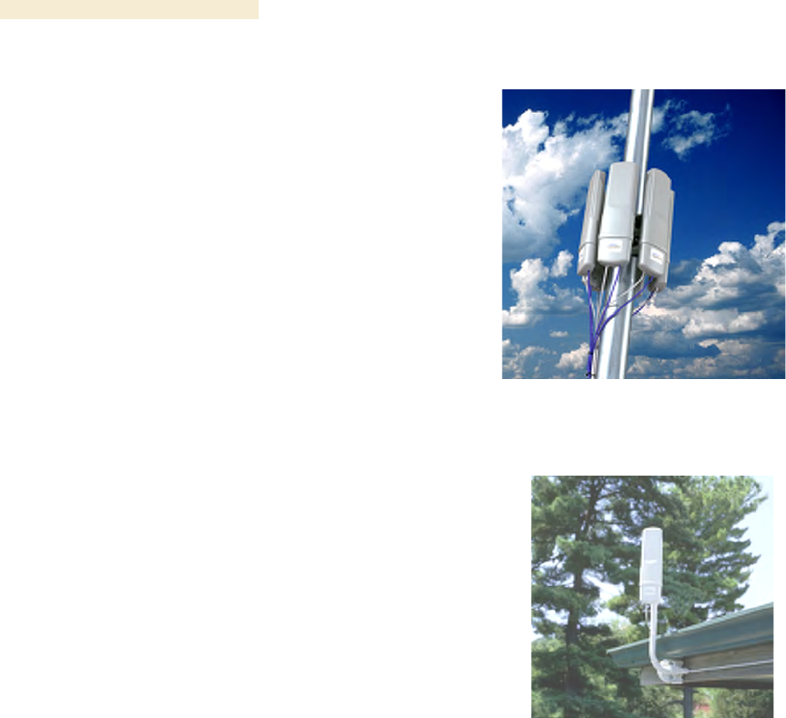
Overview of Canopy Networks Release 8
50 Draft 2 for Regulatory Review Issue 2, December 2006
5.1.3 Access Point Cluster
The AP cluster consists of two to six APs
that together distribute network or Internet
services to a community of 1,200 or fewer
subscribers. Each AP transmits and
receives in a 60° sector. An AP cluster
covers as much as 360°.
The variety of available APs and
Advantage APs in frequency band range,
power adjustability, and antenna
configuration is shown under Acquiring a
Canopy Demonstration Kit, beginning on
Page 117.
An AP cluster is pictured in Figure 2.
Figure 2: Pole-mounted AP cluster
5.1.4 Canopy Subscriber Module
The Subscriber Module (SM) is a customer premises
equipment (CPE) device that extends network or
Internet services by communication with an AP. The
SM is configurable through a web interface.
The variety of available SMs and Advantage SMs in
frequency band range, power adjustability, and
antenna configuration is shown under Acquiring a
Canopy Demonstration Kit, beginning on Page 117.
A Canopy SM can communicate with either a
Canopy AP or an Advantage SP.
An SM mounted directly to a structure is pictured in
Figure 3.
Figure 3: Structure-mounted SM
5.1.5 Advantage Subscriber Module
The Canopy Advantage SM provides the same configurability and services as the
Canopy SM. However, in a link with the Advantage AP, the Advantage SM provides
uncapped sustained throughput through the 2X operation feature. See 2X Operation on
Page 91. An Advantage SM can communicate with only an Advantage AP.
5.1.6 Canopy Lite Subscriber Module
Canopy Lite SMs cost less and provide less throughput than regular Canopy SMs. They
support the same radio frequencies, interference tolerance, and product reliability. They
give operators the additional option to serve cost-sensitive customers who want standard
services (web browsing, email, VoIP, and downloads), but do not require the higher
throughput that is available with a regular Canopy SM. Canopy Lite SMs support an
aggregate(uplink plus downlink) throughput of 512 kbps. Through purchased floating
licenses that Prizm manages, they are upgradeable to 1, 2, 4, or 7 Mbps aggregate
throughput. A Canopy Lite SM can communicate with only a Canopy Advantage AP.
A comparison of the Canopy Lite SM to the Canopy SM and Advantage SM is provided in
Table 28 on Page 100.
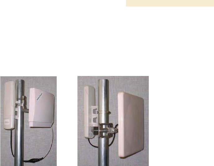
Release 8 Overview of Canopy Networks
March 200 Through Software Release 6.
Issue 2, December 2006 Draft 2 for Regulatory Review 51
5.1.7 900-MHz AP and SM
Canopy 900 MHz AP and SM modules operate at 3.3 Mbps (compared to 10 Mbps for
other Canopy frequency bands). With Downlink Data set to 75% in the AP, the AP
supports high throughput to an SM.
Figure 4: Examples of flat panel antennas with 900-MHz modules
These 900-MHz modules run the same software and provide the same parameters,
network features, and connections as all other Canopy APs and SMs. The physics of
longer-wavelength 900 MHz, the power allowed by regulatory authorities, and the low
required level of Canopy Carrier-to-Interference (C/I) ratio combine to support
◦ line of sight (LOS) range of up to 40 miles (over 64 km)
◦ increased non-line of sight (NLOS) range, depending on RF considerations such
as foliage, topography, and obstructions.
When collocated with a Canopy SM of another frequency band range, the 900-MHz AP
may serve, without a tower or BH, as a remote AP (see Deploying a Remote AP on
Page 147). 900-MHz AP/SM links are logical choices for extending radio networks where
you wish to
◦ add subscriber-handling capacity to a tower that is either
− fully used in the other frequency band ranges.
− not available to any other frequency band range.
◦ reach sparsely populated areas.
◦ penetrate foliage.
◦ add a remote AP behind an SM that operates in another frequency band range.

Overview of Canopy Networks Release 8
52 Draft 2 for Regulatory Review Issue 2, December 2006
5.1.8 Backhaul Module
A pair of Backhaul Modules (BHs) provide point-to-point
connectivity as either
◦ a standalone link
◦ a link through a cluster management module to an
AP cluster.
You must configure a BH as either a timing master (BHM)
or timing slave (BHS). The BHM provides synchronization
signal (sync) to the BHS.
A BH mounted to a passive reflector dish is pictured in
Figure 5. Carrier applications for these modules include
reaching remote AP clusters, interconnecting campus
buildings or remote branch offices, extending private
branch exchange (PBX) circuits, backhauling cell sites, and
extending central office T1s/E1s.
These BHs are supported by this user guide. See Realizing
a Wireless Backhaul Network on Page 47.
Figure 5: Dish-mounted
10- or 20-Mbps BH
5.1.9 OFDM Series Backhaul Modules
These high-speed BHs provide point-to-point
data connectivity via a 5.4- or 5.7-GHz wireless
Ethernet bridge that operates at broadband
data rates. They provide non-Line of Sight
(NLOS) operation through the use of
Orthogonal Frequency Division Multiplex
(OFDM) modulation and Transmit Diversity.
Transmissions penetrate foliage, such that
almost universal coverage is typical at short
range.
The link consists of a pair of identical BHs that
transmit and receive on an automatically
selected but configurable frequency. The
installer sets up one unit as the master and the
other as the slave. (Each unit is preconfigured
as master or slave but can be reconfigured to
the other.) These modules are available as
either connectorized for an external antenna or
equipped with an integrated antenna.
Each end of the link consists of both
◦ an outdoor transceiver (ODU) that
contains all the radio and networking
electronics (see Figure 6 and Figure 7)
◦ an indoor passive connection box
(PIDU) that contains status indicators
and network connection (see Figure 8
and Figure 9.
Available modulations are 30/60 Mbps and
150/300 Mbps. A 30-Mbps BH is software-
Figure 6: 30/60- or 150/300-Mbps
Backhaul Module, integrated antenna
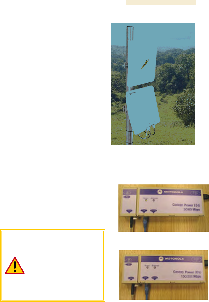
Release 8 Overview of Canopy Networks
March 200 Through Software Release 6.
Issue 2, December 2006 Draft 2 for Regulatory Review 53
upgradable to 60 Mbps, and a 150-Mbps BH is
likewise software-upgradable to 300 Mbps.
Products in this series are supported by
dedicated user guides.
By default, these BHs use a proprietary data
scrambling and encryption scheme. The 30/60-
Mbps BHs have AES encryption available as a
licensed option. The 150/300-Mbps BHs
support virtual private networking (VPN).
Carrier applications for these modules include
reaching remote AP clusters, interconnecting
campus buildings or remote branch offices,
extending private branch exchange (PBX)
circuits, backhauling cell sites, and extending
central office T1s/E1s.
(OFDM Series BHs were previously available
in 45-Mbps modulation, which can be upgraded
to 60 Mbps by software.)
Figure 7: 30/60- or 150/300-Mbps
Backhaul Module, connected to
external antenna
5.1.10 Power Indoor Units for OFDM Series Backhaul Modules
Canopy also offers the required power indoor
unit (PIDU) that generates the voltage for the
30/60- or 150/300-Mbps BHs. The PIDU
provides status indicators for the ODU.
Examples of these PIDUs are shown in Figure 8
and Figure 9.
CAUTION!
The PIDU for the 30/60-Mbps BH
and the PIDU for the
150/300-Mbps BH are clearly
distinguished by their front labels.
These units are unique and are not
interchangeable under any
circumstances. Their pinouts vary.
Using any power unit other than the
proper one of these two will destroy
the module.
Figure 8: PIDU for 30/60-Mbps BH
Figure 9: PIDU for 150/300-Mbps BH
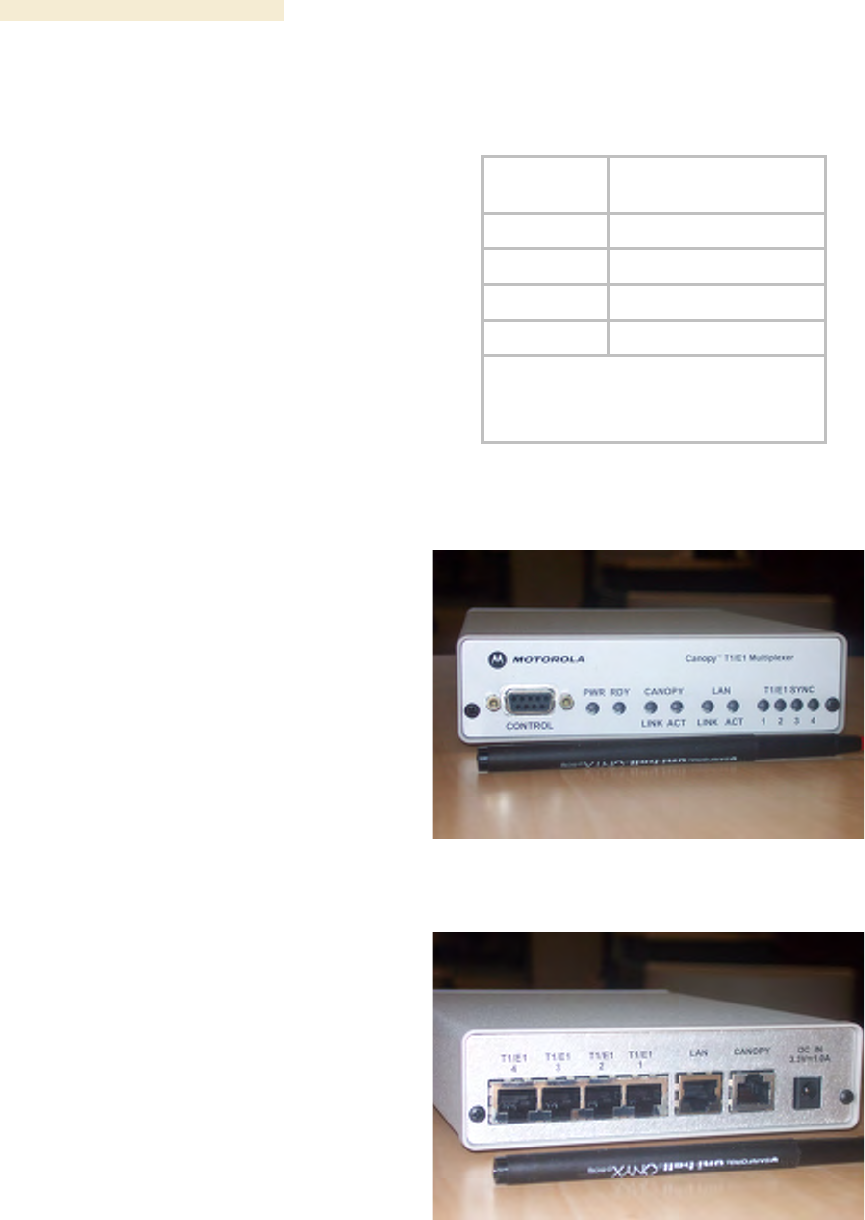
Overview of Canopy Networks Release 8
54 Draft 2 for Regulatory Review Issue 2, December 2006
5.1.11 Radio Adjustable Power Capabilities
To help network operators become or
remain compliant with applicable
regulations in their regions and nations,
Canopy offers adjustable power radios
in various frequency band ranges, as
indicated in Table 7.
See also Adjusting Transmitter Output
Power on Page 326 to ensure that your
radios do not exceed the maximum
permitted EIRP.
Table 7: Adjustable power radios
Frequency
Band Range
Introduced in Canopy
System Release
900 MHz1
7.0
2.4 GHz1
4.2.7
5.4 GHz2
4.2.7
5.7 GHz1
6.1
NOTES:
1. As a distinct part number.
2. In the base model.
5.1.12 T1/E1 Multiplexer
The Canopy T1/E1 Multiplexer
converts the data stream from T1/E1
ports into Ethernet packets that are
then transported over the Canopy BH
link. This enables up to three T1 (or
up to two E1) circuits to be extended
over Ethernet networks. The T1/E1
Multiplexer is available in two power
configurations:
◦ an external 3.3-v DC power
source from a 120/240-v AC
adapter (supplied by Canopy)
◦ an optional connection to an
external −48 v DC supply for
battery backup.
The T1/E1 Multiplexer supports
◦ synchronous TDM-based
services over wireless
Ethernet networks.
◦ CAS signaling transparent to
all other signaling protocols
on T1/E1.
◦ 10Base-T/100Base-TX uplink
to the network.
◦ management interfaces.
◦ simplified troubleshooting
through T1/E1 line loopback
test.
Figure 10: T1/E1 Multiplexer, front view
Figure 11: T1/E1 Multiplexer, rear view

Release 8 Overview of Canopy Networks
March 200 Through Software Release 6.
Issue 2, December 2006 Draft 2 for Regulatory Review 55
Applications include
◦ obviating leased lines.
◦ implementing wireless PBX networking.
◦ establishing cellular backhaul links.
◦ providing homeland security backup or emergency voice networks.
◦ routing LAN/WAN data on excess bandwidth.
This product is supported by the dedicated document Canopy T1/E1 Multiplexer User
Guide.
5.1.13 Cluster Management Module-2 (Part 1008CK-2)
The Cluster Management Module-2 (CMM2) provides power, GPS timing from an
antenna that is included, and networking connections for an AP cluster. The CMM2 can
also connect to a BH, in which case the CMM2 is the central point of connectivity for the
entire site. The CMM2 can connect as many as eight collocated modules—APs, BHMs,
BHSs—and an Ethernet feed.
The CMM2 requires two cables for each connected module:
◦ One provides Ethernet communications and power. This cable terminates in an
RJ-45 connector.
◦ The other provides synchronization (sync), GPS status, and time and date in a
serial interface. This cable terminates in an RJ-11 connector.
A CMM2 is pictured in Figure 12. A CMM2 as part of a mounted Canopy system is
pictured in Figure 13.
Figure 12: CMM2 enclosure
Figure 13: CMM2 pole-mounted

Overview of Canopy Networks Release 8
56 Draft 2 for Regulatory Review Issue 2, December 2006
5.1.14 Cluster Management Module micro (Part 1070CK)
The Cluster Management Module micro (CMMmicro) provides power, GPS timing, and
networking connections for an AP cluster. Unlike the CMM2, the CMMmicro is
configurable through a web interface.
The CMMmicro contains an 8-port managed switch that supports Power over Ethernet
(PoE)2 on each port and connects any combination of APs, BHMs, BHSs, or Ethernet
feed. The CMMmicro can auto-negotiate speed to match inputs that are either
100Base-TX or 10Base-T, and either full duplex or half duplex, where the connected
device is set to auto-negotiate. Alternatively, these parameters are settable.
A CMMmicro requires only one cable, terminating in an RJ-45 connector, for each
connected module to distribute
◦ Ethernet signaling.
◦ power to as many as 8 collocated modules—APs, BHMs, or BHSs. Through a
browser interface to the managed switch, ports can be powered or not.
◦ sync to APs and BHMs. The CMMmicro receives 1-pulse per second timing
information from Global Positioning System (GPS) satellites through an antenna
(included) and passes the timing pulse embedded in the 24-V power to the
connected modules.
GPS status information is available at the CMMmicro, however
◦ CMMmicro provides time and date information to BHMs and APs if both the
CMMmicro is operating on CMMmicro Release 2.1 or later and the AP/BHM is
operating on Canopy System Release 4.2 or later.
See Time Tab of the AP on Page 191.
◦ CMMmicro does not provide time and date information to BHMs and APs if either
the CMMmicro is operating on a release earlier than CMMmicro Release 2.1 or
the AP/BHM is operating on a release earlier than Canopy System Release 4.2.
5.1.15 GPS Antenna
The Motorola GPS antenna provides either
◦ timing pulses to the CMMmicro.
◦ timing pulses and positioning information to
the CMM2.
The GPS antenna is pictured in Figure 14.
Figure 14: Motorola GPS antenna
2 Through a proprietary scheme, different from IEEE Standard 803.af. Also, BHs in the OFDM
Series use yet another proprietary scheme.

Release 8 Overview of Canopy Networks
March 200 Through Software Release 6.
Issue 2, December 2006 Draft 2 for Regulatory Review 57
5.1.16 Surge Suppressor (Part 300SS)
The 300SS Surge Suppressor provides a path to
ground (Protective Earth
) that protects connected
equipment from near-miss lightning strikes. A
300SS is pictured in Figure 15.
Figure 15: 300SS surge suppressor
5.1.17 Accessory Components
In addition to the above modules, the following accessories are available.
Power Supplies
The various power supplies available for Canopy modules are listed in Table 8.
Table 8: Power supply descriptions
For Use With
Part
Number
Voltage (AC)
Cycles per
Second (Hz)
Includes
ACPS81WA
100 to 240
50 to 60
US IEC line cord
CMMmicro
ACPS81W-02A
100 to 240
50 to 60
no IEC line cord
ACPS110-03A1
120
50 to 60
US plug
ACPSSW-09A3
90 to 240
50 to 60
US, Euro, and UK
adaptors
ACPSSW-10A3
90 to 240
50 to 60
Argentina adaptor
ACPSSW-11A3
90 to 240
50 to 60
Australia adaptor
Canopy radio2
(except OFDM
backhauls)
ACPSSW-12A3
90 to 240
50 to 60
China adaptor
ACPSSW200-02A4
100 to 250 AC
or −48 DC
47 to 63
30/60-Mbps
OFDM BH
ACPSSW200-01A
100 to 250
47 to 63
150/300-Mbps
OFDM BH
ACPSSW200-03A5
100 to 250
47 to 63
US, Euro, and UK
leads
NOTES:
1. Pictured in Figure 16.
2. Single transceiver.
3. Pictured in Figure 17.
4. Pictured in Figure 8 on Page 53.
5. Pictured in Figure 9 on Page 53.
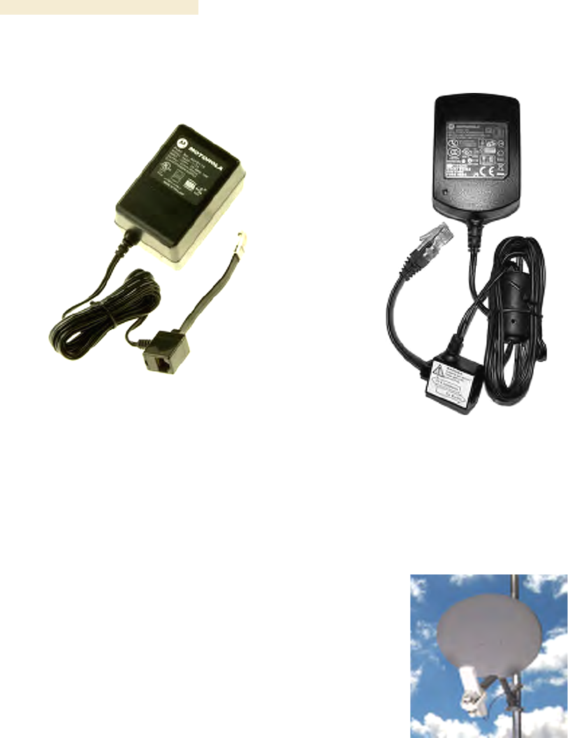
Overview of Canopy Networks Release 8
58 Draft 2 for Regulatory Review Issue 2, December 2006
Figure 16: ACPS110-03A power supply
Figure 17: ACPSSW-09A power supply
Passive Reflector Dish Assembly
The 27RD Passive Reflector Dish on both ends
of a BH link extends the distance range of the
link and focuses the beam into a narrower
angle to reduce interference. The 27RD on an
SM only helps to reduce interference. The
module support tube provides the proper offset
focus angle. See Figure 18.
For 5.n-GHz radios, the reflector gain is 18dB
and the beam width is 6° at 3 dB. For 2.4-GHz
radios, the reflector gain is 11dB and the beam
width is 17° at 3 dB. These beam width
statements apply to both azimuth and elevation
in each case.
Figure 18: 27RD with mounted module

Release 8 Overview of Canopy Networks
March 200 Through Software Release 6.
Issue 2, December 2006 Draft 2 for Regulatory Review 59
Module Support Brackets
The SMMB1 support bracket facilitates
mounting the SM to various surfaces of a
structure and has slots through which chimney
straps can be inserted. An SMMB1 is pictured
in Figure 19.
The SMMB2 is a heavy duty mounting bracket
for the 900-MHz connectorized SM and its
external antenna.
The BH1209 is a pole-mount bracket kit for
Canopy backhaul modules.
Figure 19: SMMB1 SM support bracket
Cables
Canopy modules that are currently or recently sold can auto-sense whether the Ethernet
cable is wired as straight-through or crossover. Some modules that were sold earlier
cannot. The MAC address, visible on the module, distinguishes whether the module can.
All CMMmicros can auto-sense the cable scheme.
Where a non auto-sensing module is deployed
◦ a straight-through cable must be used for connection to a network interface card
(NIC).
◦ a crossover cable must be used for connection to a hub, switch, or router.
Canopy-recommended Ethernet and sync cables can be ordered in lengths up to 328 ft
(100 m) from Best-Tronics Manufacturing, Inc. at
http://www.best-tronics.com/motorola.htm. These cables are listed in Table 9 and
Table 10.
Table 9: Recommended outdoor UTP Category 5E cables
Best-Tronics
Part #
Description
BT-0562
RJ-45 TO RJ-45; straight-through Ethernet cable
BT-0562S
RJ-45 TO RJ-45; shielded straight-through Ethernet cable
BT-0565
RJ-45 TO RJ-45; crossover Ethernet cable
BT-0565S
RJ-45 TO RJ-45; shielded crossover Ethernet cable
BT-0563
RJ-11 TO RJ-11; sync cable
BT-0563S
RJ-11 TO RJ-11; shielded sync cable

Overview of Canopy Networks Release 8
60 Draft 2 for Regulatory Review Issue 2, December 2006
NOTE:
Shielded cable is strongly recommended for all AP cluster and BH installations.
Table 10: Recommended indoor UTP Category 5E cables
Best-Tronics
Part #
Description
BT-0596
RJ-45 TO RJ-45; straight-through Ethernet cable
BT-0595
RJ-45 TO RJ-45; crossover Ethernet cable
Approved Ethernet cables can also be ordered as bulk cable:
◦ CA-0287
◦ CA-0287S (shielded)
Canopy-approved antenna cables can be ordered in lengths up to 100 ft (30.4 m),
as listed in Table 11.
Table 11: Recommended antenna cables
Best-Tronics
Part #
Description
BT-0564
N TO N GPS antenna cable for CMM2
BT-0716
BNC TO N GPS antenna cable for CMMmicro
Category 5 Cable Tester
For purchase within the U.S.A., the CTCAT5-01 Cable Tester is available.
Override Plug
An override plug (sometimes called a default plug) is available to provide access to a
module whose password and/or IP address have been forgotten. This plug allows the AP,
SM, or BH to be accessed using IP address 169.254.1.1 and no password. During the
override session, you can assign any new IP address and set either or both user
passwords (display-only and/or full access) as well as make other parameter changes.
This plug is available from Best-Tronics Manufacturing, Inc. at
http://www.best-tronics.com/motorola.htm as Part BT-0583 (RJ-11 Default Plug).
Alternatively if you wish, you can fabricate an override plug. For instructions, see
Procedure 36 on Page 376 and the pinout in Figure 146 on Page 376.
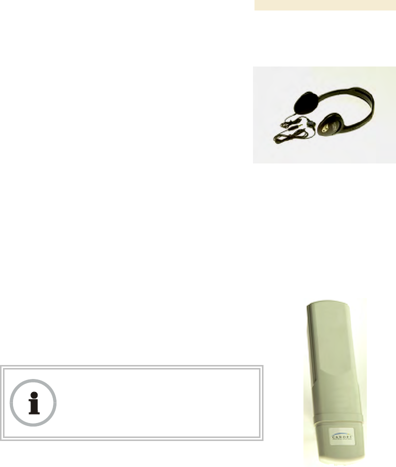
Release 8 Overview of Canopy Networks
March 200 Through Software Release 6.
Issue 2, December 2006 Draft 2 for Regulatory Review 61
Alignment Headset
The ACATHS-01 Alignment Headset facilitates the
operation of precisely aiming an SM toward an AP (or
a BHS toward a BHM). This device produces infinitely
variable
◦ pitch, higher when the received signal is
stronger.
◦ volume, louder when jitter is less.
An ACATHS-01 is pictured in Figure 20.
Pinouts for an alternative listening device are provided
under Alignment Tone—Technical Details on
Page 184.
Figure 20: ACATHS-01
alignment headset
Module Housing
The HSG-01 Canopy Plastic Housing is available for
replacement of a damaged housing on a module that is
otherwise functional. The HSG-01 is pictured in
Figure 21.
The HSG-01 and all module housings of this design
provide clearances for cable ties on the Ethernet and sync
cables.
RECOMMENDATION:
Use 0.14” (40-lb tensile strength) cable ties
to secure the Ethernet and sync cables to
the cable guides on the module housing.
For the Ethernet cable tie, the Ethernet cable groove is
molded lower at the top edge. For the sync cable tie,
removal of a breakaway plug provides clearance for the
sync cable, and removal of two breakaway side plates
provides clearance for the sync cable tie.
Figure 21: HSG-01 Housing
5.2 FREQUENCY BAND RANGES
In the 2.4-, 5.2-, 5.1-, 5.4-, and 5.7-GHz frequency band ranges, Canopy APs, SMs, and
BHs are available. Additionally, in the 900-MHz frequency band range, Canopy APs and
SMs are available. National restrictions may apply. See Legal and Regulatory Notices on
Page 489.
To avoid self-interference, a Canopy network typically uses two or more of these ranges.
For example, where properly arranged, all AP clusters and their respective SMs can use
the 2.4-GHz range where the BH links use the 5.7-GHz range. In this scenario,
subscriber links can span as far as 5 miles (8 km) with no reflector dishes, and the BH
links can span as far as 35 miles (56 km) with reflector dishes on both ends.
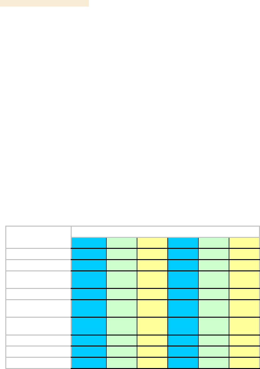
Overview of Canopy Networks Release 8
62 Draft 2 for Regulatory Review Issue 2, December 2006
Within this example network, wherever the 2.4-GHz module is susceptible to interference
from other sources, AP clusters and their linked SMs may use the 5.2-GHz range to span
as far as 2 miles (3.2 km) with no reflector dishes. The network in this example takes
advantage of frequency band range-specific characteristics of Canopy modules as
follows:
◦ The 900-MHz modules cover a larger area, albeit with lower throughput, than
modules of the other frequency bands. The 900-MHz modules can be used to
− penetrate foliage
− establish links that span greater distances
− add subscribers
− add overall throughput where modules of other frequency bands cannot be
used (such as where interference would result or space on a tower is
limited).
◦ The 2.4-GHz frequency band range supports AP/SM links of greater than 2-mile
spans (with no reflectors).
◦ The 5.7-GHz frequency band range supports BH links that span as far as 35
miles.
5.3 CANOPY PRODUCT COMPARISONS
5.3.1 Canopy Product Applications
The product applications per frequency band range are is summarized in Table 12.
Table 12: Product applications per frequency band range
Frequency Band Range
Product
900 MHz
2.4 GHz
5.1 GHz
5.2 GHz
5.4 GHz
5.7 GHz
Access Point Module
●
●
●
●
●
●
Subscriber Module
●
●
●
●
●
●
Subscriber Module with
Reflector1
●
●
●
●
Backhaul Module
●
●
●
●
●
Backhaul Module with
Reflector1
●
●
●
●
●
OFDM Series
Backhaul Module
●
●
CMM2
●
●
●
●
●
●
CMMmicro
●
●
●
●
●
●
T1/E1 Multiplexer
●
●
●
●
●
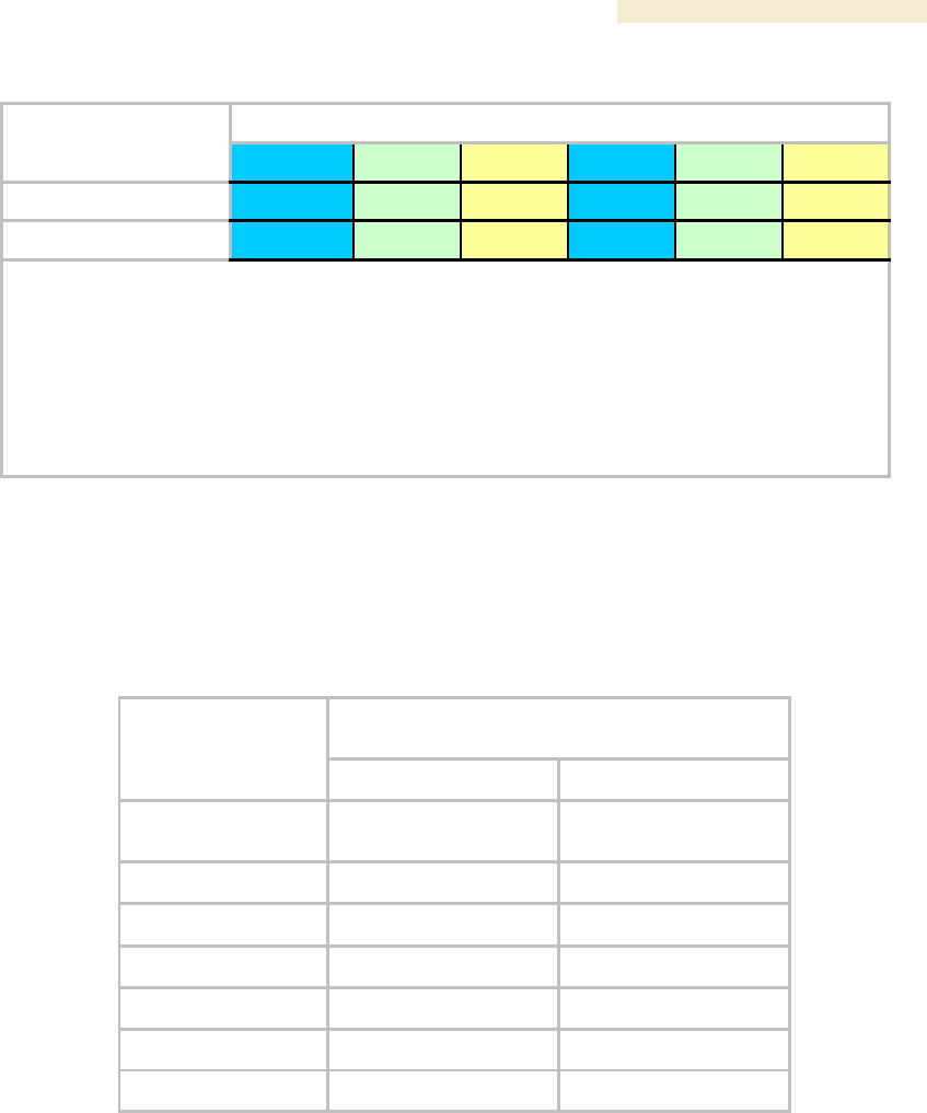
Release 8 Overview of Canopy Networks
March 200 Through Software Release 6.
Issue 2, December 2006 Draft 2 for Regulatory Review 63
Frequency Band Range
Product
900 MHz
2.4 GHz
5.1 GHz
5.2 GHz
5.4 GHz
5.7 GHz
Power supply
●
●
●
●
●
●
Surge suppressor
●
●
●
●
●
●
NOTES:
1. National or regional regulations may limit EIRP to the same as without a reflector, and
therefore require Transmit Output Power to be reduced. See National and Regional
Regulatory Notices on Page 489. In these cases
◦ the reflector used with an SM reduces beamwidth to reduce interference, but does not
increase the range of the link.
◦ the reflector on both ends of a BH link reduces beamwidth to reduce interference and also
increases the range of the link.
5.3.2 Link Performance and Encryption Comparisons
The encryption options on Canopy point-to-multipoint (PTMP) products are summarized
in Table 13. Typical Line-of-Site (LOS) range and aggregate useful throughput for
Canopy PTMP links are summarized in Table 14.
Table 13: Products with encryption options available per frequency band, PTMP links
Products available with the following
encryption options
Frequency Band
DES or none
AES or none
2.4 GHz @100 mW
(ETSI)
●
●
2.4 GHz @ 1W
●
●
5.1 GHz
●
5.2 GHz
●
●
5.4 GHz
●
●
5.7 GHz
●
●
900 MHz
●
●

Overview of Canopy Networks Release 8
64 Draft 2 for Regulatory Review Issue 2, December 2006
Table 14: Typical range and throughput per frequency band, PTMP links
Advantage AP
Canopy AP
Range
Range
Frequency
Band
no SM
Reflector
mi (km)
with SM
Reflector
mi (km)
Aggregate
Throughput
Mbps
Round-
trip
Latency
msec
no SM
Reflector
mi (km)
with SM
Reflector
mi (km)
Aggregate
Throughput3
Mbps
Round-
trip
Latency
msec
0.3 (0.5)
0.3 (0.5) 1
14
6
2.4 GHz
ETSI
0.6 (1)
0.6 (1) 1
7
6
0.6 (1)
0.6 (1) 1
7
20
2.5 (4)
7.5 (12)
14
6
2.4 GHz
5 (8)
15 (24)
7
6
5 (8)
15 (24)
7
20
1 (1.6)
na
14
6
5.1 GHz
2 (3.2)
na
7
6
2 (3.2)
na
7
20
1 (1.6)
na2
14
6
5.2 GHz
2 (3.2)
na2
7
6
2 (3.2)
na2
7
20
1 (1.6)
1 (1.6) 1
14
6
5.4 GHz
2 (3.2)
2 (3.2) 1
7
6
2 (3.2)
2 (3.2)1
7
20
1 (1.6)
5 (8)
14
6
5.7 GHz
2 (3.2)
10 (16)
7
6
2 (3.2)
10 (16)
7
20
900 MHz4
40 (64)
na
4
15
NOTES:
2. In Europe, 2.4-GHz ETSI and 5.4-GHz SMs can have a reflector added to focus the antenna pattern and
reduce interference, but transmit output power must be reduced to maintain the same EIRP as without a
reflector, so the throughput and range specs for PTMP links remain the same.
3. In the USA and Canada, the use of a reflector with a full power radio in the 5.2-GHz frequency band is not
allowed.
4. These values assume a hardware series P9 AP running hardware scheduler. When running software
scheduler on a series P7, P8, or P9 AP, aggregate throughput drops to 6.2 Mbps, and only 4 Mbps is available
to any one SM. (Series P7 and P8 APs can only run software scheduler.)
5. All 900-MHz APs are Advantage APs.
GENERAL NOTES:
Range is affected by RF conditions, terrain, obstacles, buildings, and vegetation.
An Advantage AP in other than 900 MHz has an aggregate (sum of uplink plus downlink) throughput or capacity of
14 Mbps, if RF conditions, range, and SM hardware version permit.
An Advantage SM in other than 900 MHz has an aggregate sustained throughput of 14 Mbps if RF conditions and
range permit.
A regular SM can burst to 14 Mbps if RF conditions and range permit, then run at 7 Mbps sustained throughput.
The encryption options on Canopy point-to-point (PTP) products are summarized in
Table 15. Typical Line-of-Site (LOS) range and aggregate useful throughput for Canopy
PTP links are summarized in Table 16.

Release 8 Overview of Canopy Networks
March 200 Through Software Release 6.
Issue 2, December 2006 Draft 2 for Regulatory Review 65
Table 15: Products with encryption options available per frequency band, PTP links
Products available with the following encryption
options
Frequency Band
Modulation
Rate (Mbps)
DES or
none
AES or
none
Proprietary
Proprietary or AES
licensed upgrade
10
●
●
2.4 GHz @100
mW
(ETSI)
20
●
●
10
●
●
2.4 GHz @ 1W
20
●
●
10
●
5.1 GHz
20
●
10
●
●
5.2 GHz
20
●
●
10
●
●
5.2 GHz ER
20
●
●
10
●
●
20
●
●
30
60
●
5.4 GHz
150
300
●
10
●
●
20
●
●
30
60
●
5.7 GHz
150
300
●

Overview of Canopy Networks Release 8
66 Draft 2 for Regulatory Review Issue 2, December 2006
Table 16: Typical range and throughput per frequency band, PTP links
Throughput
Frequency Band
Modulation
Rate (Mbps)
No Reflectors
Both Reflectors
10
7.5 Mbps to 2 km
7.5 Mbps to 16 km
2.4 GHz @100 mW
(ETSI)
20
14 Mbps to 1 km
14 Mbps to 8 km
10
7.5 Mbps to 5 mi (8 km)
7.5 Mbps to 35 mi (56 km)
2.4 GHz @ 1W
20
14 Mbps to 3 mi (5 km)
14 Mbps to 35 mi (56 km)
10
7.5 Mbps to 2 mi (3.2 km)
5.1 GHz
20
14 Mbps to 2 mi (3.2 km)
10
7.5 Mbps to 2 mi (3.2 km)
5.2 GHz
20
10
7.5 Mbps to 10 mi (16 km)
5.2 GHz ER
20
14 Mbps to 5 mi (8 km)
10
7.5 Mbps to 2 mi (3.2 km)
7.5 Mbps to 10 mi (16 km)1
20
14 Mbps to 1 mi (1.6 km)
14 Mbps to 5 mi (8 km)1
30
dynamically variable from 1.5
to 21 Mbps aggregate2
60
dynamically variable from 3 to
43 Mbps aggregate2
150
dynamically variable from 7 to
150 Mbps aggregate2
5.4 GHz
300
dynamically variable from 14
to 300 Mbps aggregate2
10
7.5 Mbps to 2 mi (3.2 km)
7.5 Mbps to 35 mi (56 km)
20
14 Mbps to 1 mi (1.6 km)
14 Mbps to 35 mi (56 km)
30
dynamically variable from 1.5
to 21 Mbps aggregate2
60
dynamically variable from 3 to
43 Mbps aggregate2
150
dynamically variable from 7 to
150 Mbps aggregate2
5.7 GHz
300
dynamically variable from 14
to 300 Mbps aggregate2
NOTES:
1. These ranges are with power reduced to within 1 W (30 dBm) EIRP.
2. Use the Link Estimator tool to estimate throughput for a given link.

Release 8 Overview of Canopy Networks
March 200 Through Software Release 6.
Issue 2, December 2006 Draft 2 for Regulatory Review 67
5.3.3 Cluster Management Product Comparison
Canopy offers a choice between two products for cluster management: CMM2 and
CMMmicro. Your choice should be based on the installation environment and your
requirements. The similarities and differences between these two products are
summarized in Table 17.
Table 17: Cluster management product similarities and differences
Characteristic
CMM2
CMMmicro
Approximate size
17” H x 13” W x 6.5” D
(43 cm H x 33 cm W x 7 cm D)
12” H x 10” W x 3” D
(30 cm H x 25 cm W x 8 cm D)
Approximate weight
25 lb ( 11.3 kg)
8 lb (3.5 kg)
Cabling
◦ one Ethernet/power cable per
radio.
◦ one sync cable per radio.
one Ethernet/power/sync cable per
radio.
Canopy network
interconnection
8 Ethernet ports
8 Ethernet ports
Data throughput
auto-negotiates to full or half duplex
auto-negotiates to full or half duplex
Ethernet operating
speed standard
auto-negotiates to 10Base-T or
100Base-TX
auto-negotiates to 10Base-T or
100Base-TX
Additional Ethernet
ports
one for data feed
one for local access
(notebook computer)
none
Power supply
integrated 24-V DC to power APs,
BHs, and GPS receiver
external 24-V DC to power APs, BHs,
and GPS receiver
SNMP management
capability
none
provided
Sync (to prevent
self-interference)
carried by the additional serial cable
to each AP and BHM
embedded in power-over-Ethernet
cable
Time & Date
carried by the additional serial cable
to each AP and BHM
provided by NTP (Network Time
Protocol). CMMmicro can be an NTP
server.
Weatherized
enclosure and power supply
only the enclosure (not the power
supply)
Web interface
none
web pages for status, configuration,
GPS status, and other purposes
NOTE:
Auto-negotiation of data throughput and Ethernet operating speed depend on the connected device
being set to auto-negotiate as well.

Overview of Canopy Networks Release 8
68 Draft 2 for Regulatory Review Issue 2, December 2006
5.4 ANTENNAS FOR CONNECTION TO 900-MHz MODULES
Like the 2.4-, 5.2-, 5.4-, and 5.7-GHz module, the 900-MHz connectorized module has
◦ the same housing.
◦ a covered Ethernet port.
◦ a utility port for alignment headset, sync cable to CMM2, or override plug.
The 900-MHz AP or SM is available either
◦ as a connectorized unit with a 16-inch (approximately 40-cm) cable with a male
N-type connector for connection to the antenna.
◦ with an integrated antenna in a different form factor.
5.4.1 Certified Connectorized Flat Panel Antennas
Motorola has certified through regulatory agencies four connectorized flat panel antenna
options. Motorola offers one of these, whose attributes include
◦ gain—10 dBi
◦ dimensions—8.8 x 8.1 x 1.6 inches (22.4 x 20.6 x 4.06 cm)
◦ weight—1.2 lbs (0.54 kg)
◦ polarization—vertical or horizontal
◦ cable—12-inch (30.5 cm)
◦ connector—female N-type
◦ beamwidth—approximately 60° vertical and 60° horizontal at 3 dBm
Motorola has certified three other antennas, which are available through Canopy
resellers. The attributes of one of these other certified antennas include
◦ gain—10 dBi
◦ dimensions—12 x12 x 1 inches (30.5 x 30.5 x 2.5 cm)
◦ weight—3.3 lbs (1.5 kg)
◦ polarization—vertical or horizontal
◦ connector—female N-type
◦ beamwidth—approximately 60° vertical and 60° horizontal at 3 dBm
Examples of these antennas are pictured in Figure 4 on Page 51.
5.4.2 Third-party Certified Connectorized Flat Panel Antenna
A third party may certify additional antennas for use with the Canopy connectorized
900-MHz module.

Release 8 Overview of Canopy Networks
March 200 Through Software Release 6.
Issue 2, December 2006 Draft 2 for Regulatory Review 69
5.5 ADJUNCTIVE SOFTWARE PRODUCTS
The capabilities of available applications and tools are summarized for comparison in
Table 18. In this table CNUT represents Canopy Network Updater Tool, Release 1.1 or
later, and BAM represents Bandwidth and Authentication Manager, Release 2.0 or later.
Table 18: Canopy applications and tools
Application or Tool
Capability
Prizm
CNUT
BAM
authenticates SMs
●
●
controls authentication in APs
●
●
manages Committed Information Rate (CIR)
●
●
has dependency on another application3
●
automatically discovers elements
●
●
exports network information with hierarchy
●
●
supports user-defined folder-based operations
●
●
senses FPGA version on an element
●
●
upgrades FPGA version on an element
●
enables/disables hardware scheduling
●
manages the high-priority channel
●
●
imports network information with hierarchy
●
●
interface to a higher-level network management
system (NMS)
●
interface to an operations support system (OSS)
●
manages Maximum Information Rate (MIR)
●
●
automatically works from root (highest) level
●
element selection can be individual or multiple
●
●
●
element selection can be criteria based
●
element selection can be user-defined branch
●
●
senses software release on an element
●
●
upgrades software release on an element
●
manages VLAN parameters
●
●
provides access to element web interface
●

Overview of Canopy Networks Release 8
70 Draft 2 for Regulatory Review Issue 2, December 2006
5.6 BANDWIDTH AND AUTHENTICATION MANAGER
Canopy Bandwidth and Authentication Manager (BAM) software allows you to use
◦ a primary server to distribute bandwidth resources per subscriber, require SMs to
authenticate per AP, and deny service to unauthorized SMs.
◦ a secondary server to redundantly store identical SM bandwidth and
authentication data and become governing if the primary server goes out of
service.
◦ an optional tertiary server to do the same if both the primary and secondary
servers go out of service.
In BAM Release 2.1, subscriber administration for an SM or batch of SMs is performed
as follows:
◦ Insert the ESNs.
◦ Specify MIR and Security attributes.
◦ Specify CIR attributes.
◦ Specify whether BAM should send its stored CIR attributes.
◦ Specify VLAN attributes.
◦ Specify whether BAM should send its stored VLAN attributes.
◦ Specify VLAN IDs to associate with the SM(s).
This product is supported by the dedicated document Canopy Bandwidth and
Authentication Manager Release 2.1 User Guide and associated release notes.
The upgrade path from BAM Release 2.1 is Prizm Release 2.0. See Motorola Canopy
Prizm User Guide, Issue 3, and Motorola Canopy Prizm Release 2.0 Release Notes.
5.7 Prizm
The product name PrizmEMS is changed to Prizm in Release 2.0 and later, to reflect that
the product capabilities are expanded beyond those of the element management system
(EMS). Throughout this user guide, the name change applies to text for Release 2.0 and
for multiple releases that include 2.0. It does not apply to text that is for a previous
release. Case by case, software elements such as the GUI in the client application and
XML files on the server may retain the PrizmEMS syntax.
5.7.1 Network Definition and Element Discovery
Prizm allows the user to partition the entire Canopy network into criteria-based subsets
that can be independently managed. To assist in this task of defining networks, Prizm
auto discovers Canopy network elements that are in
◦ user-defined IP address ranges
◦ SM-to-AP relationships with APs in the user-defined range
◦ BHS-to-BHM relationships with BHMs in the user-defined range.
◦ PLV Modem-to-PLV Bridge relationships with PLV Bridges in the user-defined
range.
For a Canopy AP, SM, BHM, BHS, PLV Bridge, PLV Modem, or CMMmicro, Prizm
◦ auto discovers the element to the extent possible.

Release 8 Overview of Canopy Networks
March 200 Through Software Release 6.
Issue 2, December 2006 Draft 2 for Regulatory Review 71
◦ includes the element in the network tree.
◦ shows general information.
◦ shows Canopy information.
◦ supports Canopy-specific operations.
For a generic element, Prizm
◦ auto discovers the element as only a generic network element.
◦ includes the element in the network tree.
◦ shows general information.
◦ shows events and alerts.
◦ charts port activity.
For passive elements (such as CMM2 or a non-manageable switch or hub), Prizm allows
you to enter into the network tree a folder/group with name, asset/owner information, and
descriptive information.
Supported element types include
Canopy Access Point Module
Canopy Backhaul Master Module
Canopy Backhaul Slave Module
Canopy PrizmEMS
Canopy Subscriber Module
Cluster Management Module micro
Cluster Management Module-4
Cluster Management Module-4 Switch
Generic Group
Generic SNMP Device
Generic SNMP Device (08 Port)
Generic SNMP Device (16 Port)
Generic SNMP Device (24 Port)
Generic SNMP Device (26 Port)
High-Speed Backhaul Master Module 150/300 Mbps
High-Speed Backhaul Master Module 30/60 Mbps
High-Speed Backhaul Slave Module 150/300 Mbps
High-Speed Backhaul Slave Module 30/60 Mbps
PLV Bridge Unit
PLV Modem Unit
Ultra Light Access Point
Ultra Light Outdoor Subscriber Unit
5.7.2 Monitoring and Fault Management
Prizm receives the traps that Canopy elements send and generates an alert for each of
these. Prizm also allows the user to establish sets of criteria that would generate other
alerts and trigger email notifications. Optionally, the user can specify a trap template. In
this case, Prizm receives traps for non-Canopy elements in the network.
For any individual element that the user selects, Prizm offers text and graphed displays of
element configuration parameters and performance statistics from an interval that the
user specifies.
5.7.3 Element Management
Prizm allows the user to perform any of the following operations on any specified element
or group of elements:
◦ Manage
− large amounts of SNMP MIB data.
− module passwords.

Overview of Canopy Networks Release 8
72 Draft 2 for Regulatory Review Issue 2, December 2006
− IP addresses.
− other communications setup parameters.
− site information: Site Name, Site Location, and Site Contact parameters.
◦ Reset the element.
5.7.4 BAM Subsystem in Prizm
Prizm Release 2.0 and later integrates Canopy Bandwidth and Authentication Manager
(BAM) functionality and supports simple migration of a pre-existing BAM data into the
Prizm database. These releases also support the maintenance of authentication and
bandwidth data on a RADIUS server, to the same extent that BAM Release 2.1 (the final
release of BAM) did.
Either of the following modes is available for the Prizm server, subject to licensing:
◦ BAM-only functionality, which manages only
− authentication, bandwidth service plans, and VLAN profiles of SMs.
− authentication of Powerline LV modems.
◦ Full Prizm functionality, which manages attributes for all elements and
authentication of SMs and Powerline LV modems.
One difference between a service plan (or VLAN profile) and a configuration template
that has the identical set of attributes is that the former is a long-term association
whereas the latter is a one-time push to the element. When a service plan or VLAN
profile is modified, the change is automatically applied to all elements that have the
association. Another difference is that a configuration template cannot overwrite any
values that a service plan or VLAN profile has set in an element.
5.7.5 Northbound Interface
In Release 1.1 and later, Prizm provides three interfaces to higher-level systems:
◦ a Simple Network Management Protocol (SNMP) agent for integration with a
network management system (NMS).
◦ a Simple Object Access Protocol (SOAP) XML-based application programming
interface (API) for web services that supports integration with an operations
support systems (OSS) such as a customer relationship management (CRM),
billing, or provisioning system.
◦ console automation that allows such higher-level systems to launch and
appropriately display the Prizm management console in GUI that is custom
developed, using the PrizmEMS™ Software Development Kit (SDK), which
Canopy provides for this purpose.
Together these interfaces constitute the Northbound Interface feature. Prizm server
administrator tasks and GUI developer information are provided in the PrizmEMS™
Software Development Kit (SDK). This SDK also describes the how to define new
element types and customize the Details views.
All other features of the Prizm product are supported by the dedicated document
Motorola Canopy Prizm User Guide and associated release notes.
5.8 LICENSE MANAGEMENT
Under the original licensing regime for Canopy networks, licenses were permanently tied
to the Media Access Control (MAC) address of the equipment that was licensed or that

Release 8 Overview of Canopy Networks
March 200 Through Software Release 6.
Issue 2, December 2006 Draft 2 for Regulatory Review 73
used the licensed feature. Thus, they were not transferable. Under server-based license
management, for some functionalities, Canopy offers licenses that
◦ float upon demand within the network.
◦ are tied to only the hostID (MAC address) of the license management server for
which they were ordered.
In Release 4.2.3 and later, server-based license management adds flexibility and makes
available licenses that previously would have been held by de-commissioned equipment.
License management technology from Macrovision, based on a FLEXnet™ Publisher
license management model, provides the platform for Canopy server-based licensing.
Canopy capabilities that are authorized by licenses on this platform are FLEXenabled
products.
In this platform, the license management server checks and then either assigns or
declines to assign a license in real time. See the Canopy Networks License Manager
User Guide.
The total number of floating license keys that you need for any feature is the highest
number that you will ever want to have simultaneously in use. The proper placement of
these keys and the number and placement of fixed Canopy licenses are listed in
Table 19.
Table 19: Correct placement of license keys
In This
Release
License
Key
Must Be in Directory
If This
Platform
On This
Server
Device
C:\Program Files\Motorola\Canopy\FLEXnet\license_files
Windows
LM 1.0
License
Manager
Server
/usr/local/Canopy/FLEXnet/license_files
Enterprise
Linux
LM
Server
C:\Program Files\Motorola\Canopy\FLEXnet\license_files
Windows
/usr/local/Canopy/FLEXnet/license_files
Enterprise
Linux
LM
Server1
BAM 2.0
BAM
Server,
AP Auth
Server
(APAS),
Cap 2
/usr/local/canopy/include
Enterprise
Linux
BAM
Server2
C:\Program Files\Motorola\Canopy\FLEXnet\license_files
Windows
/usr/local/Canopy/FLEXnet/license_files
Enterprise
Linux
LM
Server1
BAM 2.1
BAM
Server,
AP Auth
Server
(APAS),
Cap 2
/usr/local/Canopy/FLEXnet/license_files
Enterprise
Linux
BAM
Server2
C:\Program Files\Motorola\Canopy\FLEXnet\license_files
Windows
/usr/local/Canopy/FLEXnet/license_files
Enterprise
Linux
LM
Server3
C:\Program Files\Motorola\Canopy\FLEXnet\license_files
Windows
PrizmEMS
1.0
PrizmEMS
Server,
Element
Pack
/usr/local/Canopy/Prizm/license_files
Enterprise
Linux
PrizmEMS
Server4

Overview of Canopy Networks Release 8
74 Draft 2 for Regulatory Review Issue 2, December 2006
In This
Release
License
Key
Must Be in Directory
If This
Platform
On This
Server
Device
C:\Program Files\Motorola\Canopy\FLEXnet\license_files
Windows
PrizmEMS
1.1
PrizmEMS
Server,
Element
Pack
/usr/local/Canopy/FLEXnet/license_files
Enterprise
Linux
LM
Server3
C:\Program Files\Motorola\Canopy\FLEXnet\license_files
Windows
Prizm 2.0
and 2.1
for full
mgmt
PrizmEMS
Server,
Element
Pack
BAM
Server,
AP Auth
Server
(APAS),
Cap 2
Canopy
Lite
/usr/local/Canopy/FLEXnet/license_files
Enterprise
Linux
LM
server5
C:\Program Files\Motorola\Canopy\FLEXnet\license_files
Windows
Prizm 2.0
and 2.1
for BAM-
only or
redundant
BAM
BAM
Server,
AP Auth
Server
(APAS),
Cap 2
Canopy
Lite
/usr/local/Canopy/FLEXnet/license_files
Enterprise
Linux
LM
server1
NOTES:
1. One key required per each deployed BAM server.
2. Copied here so that BAM can find License Manager. No additional charge for using this copy.
3. One key required per each deployed PrizmEMS server.
4. Copied here so that PrizmEMS can find License Manager. No additional charge for using this copy.
5. One BAMServer key and one PrizmEMSServer key required per each full management Prizm server.
5.9 SPECIFICATIONS AND LIMITATIONS
5.9.1 Radios
Canopy radio specifications are provided at
http://motorola.canopywireless.com/products/specshome.php.

Release 8 Overview of Canopy Networks
March 200 Through Software Release 6.
Issue 2, December 2006 Draft 2 for Regulatory Review 75
5.9.2 Cluster Management Products
Table 20: CMM2 specifications and limitations
Specification or Limitation
Canopy System Range
Max length from Cluster Management
Module to any radio
328 cable feet (100 meters)
Max length from Cluster Management
Module to GPS antenna
100 cable feet (30.5 meters)
Dimensions
17.00” H x 12.88” W x 6.50” D
(43.18 cm H x 32.72 cm W x 16.51 cm D)
Weight
25.0 lbs. (11.3 kg)
Operation Temperature
-40°F to +131°F (-40°C to +55°C)
Overall
Meets CE IP44 according to EN60529:2000
AC Input Voltage and Frequency
100 V – 240 V~, 0.7 A – 0.35 A, settable to either 230 V or 115 V
nominal input.
50 Hz – 60 Hz
Note: Applying 230 V to a unit that is set to 115 V may damage
the unit.
AC Input Power
Nominal 66 watts, max 92 watts with 8 modules connected to the
CMM at max cable length.
24-V DC Input Voltage
18 to 32 V DC, measured at CMM
24-V DC Input Power
Nominal 60 watts. Maximum 84 watts with 8 modules connected
to the CMM at maximum cable length. 9A inrush upon start-up.
24-V DC Usage
If using a typical “24V +/-5%” power supply, ensure that CMM is
within 400 cable feet (120 m) of the power supply. Use minimum
12 AWG (4 mm2) copper wire.
12-V DC Input Voltage
11.5 to 32 VDC, measured at CMM
12-V DC Usage
If using a 12V power source (typically an automobile battery in a
test or emergency situation), use 12 AWG (4 mm2) wire between
the power supply and the CMM, ensure that the CMM is within 10
cable feet (3 m) of the power supply, and ensure the modules are
within 20 cable feet (6 m) of the CMM.
Ethernet, GPS Sync, and GPS Coax
Cables
The use of cables that conform to the operational temperature of
the product as well as being UV light protected is mandatory.
Overview of Canopy Networks Release 8
76 Draft 2 for Regulatory Review Issue 2, December 2006
Table 21: CMMmicro specifications and limitations
Specification or Limitation
Canopy System Range
Enclosure Size
Approximately 12” H x 10” W x 3” D
(Approximately 30 cm H x 25 cm W x 7.5 cm D)
CMMmicro Weight (without DC power
supply)
Approximately 8 lb
(Approximately 3.5 k)
Max length from Cluster Management
Module to any radio
328 cable feet (100 meters)
Max length from Cluster Management
Module to GPS antenna
100 cable feet (30.5 meters)
Operating Temperature
-40°F to +131°F (-40°C to +55°C)
Provided DC Power Converter Input
Voltage
100 – 240 V~
Provided DC Power Converter Input
Frequency
50 – 60 Hz
CMMmicro Power Input Voltage
21.5 – 26.5 V DC
CMMmicro Power Current
3.36 A @ 24 V DC (3.75 – 3.0 A over voltage range)
Ethernet, GPS sync, and GPS coax
cables
The use of cables that conform to the operational temperature of
the product as well as having UV light protection is mandatory.
Cables can be ordered from Best-Tronics Manufacturing, Inc. at
http://www.best-tronics.com/motorola.htm.
5.9.3 300SS and 600SS Surge Suppressors
Canopy Surge Suppressor specifications are provided at
http://motorola.canopywireless.com/products/specshome.php.

Release 8 Overview of Canopy Networks
March 200 Through Software Release 6.
Issue 2, December 2006 Draft 2 for Regulatory Review 77
6 DIFFERENTIATING AMONG COMPONENTS
6.1 INTERPRETING MODEL (PART) NUMBER
The part number of a module typically represents
◦ the model number, which may indicate
− radio frequency band range.
− link distance range.
− whether the module is Canopy Advantage.
− the factory-set encryption standard.
◦ the module type.
◦ whether the reflector dish is included.
◦ the antenna scheme of the module.
◦ whether adjustable power in the module is preset to low.
◦ the modulation capability.
Radio Frequency Band Range
The leading digits usually indicate the frequency band range in which the module can
operate. For example, if the part number is 5700BH, then the frequency band range of
the module is 5.7 GHz.
↓
5
7
0
0
B
H
An exception to this general rule is that the leading digits in the part number of 5.1-GHz
modules are 52. These modules are differentiated from 5.2-GHz modules by the leading
four digits (5202 for 5.1 GHz, 5200 for 5.2 GHz).
You cannot change the frequency band range of the module.
Link Distance Range or Canopy Advantage
The third digit in the part number may indicate whether the module is an extended range,
Canopy Advantage, or Canopy model. 1 indicates extended range. For example, if the
part number is 5210BH, then the module is an extended range module. If the part
number is 5200BH, then the module is not an extended range model.
↓
5
2
0
0
B
H
6 in the third position (5760SM, for example) indicates Canopy Lite. 5 in the third position
(5250AP, for example) indicates that the module is Canopy Advantage. 0 in the third
position (5200AP, for example) indicates that the module is Canopy. However, part
numbering for 900-MHz APs and SMs differs from this general rule. All APs and SMs in
this frequency band range are Canopy Advantage, but none of their part numbers use 5
in the third position.

Overview of Canopy Networks Release 8
78 Draft 2 for Regulatory Review Issue 2, December 2006
You cannot change the link distance range of the module. However, you can license a
Canopy SM to uncap its aggregate throughput (a capability of the Advantage SM).
Encryption Standard or Frequency Band Range
The fourth digit in the part number usually indicates the encryption standard that was
preset at the factory. 1 indicates the Advanced Encryption Standard (AES). 0 indicates
the Data Encryption Standard (DES) standard. For example, if the part number is
5201BH, then transmissions from the module are encrypted according to AES. If the part
number is 5200BH, then transmissions from the module are encrypted according to DES.
↓
5
7
0
0
B
H
An exception to this general rule is that the fourth digit in the part number of 5.1-GHz
modules is 2. These modules are differentiated from 5.2-GHz modules by the leading
four digits (5202 for 5.1 GHz, 5200 for 5.2 GHz).
You cannot change the encryption basis (from DES to AES, for example), but you can
enable or disable the encryption.
Module Type
The next two alpha characters indicate the module type. For example, CK indicates that
the module is a Cluster Management Module.
↓
1
0
0
8
C
K
The module type cannot be changed.
Reflector Added
In specifications tables and price lists, the trailing characters RF or RF20 indicate that the
associated information applies to the module being
◦ mounted to the 27RD Passive Reflector Dish, in the case of specifications.
◦ ordered with the 27RD Passive Reflector Dish, in the case of price lists.
↓
2
4
0
0
B
H
R
F
2
0
However, this designation is not shown on either label of the module, and a module
ordered with the dish can be deployed without the dish.

Release 8 Overview of Canopy Networks
March 200 Through Software Release 6.
Issue 2, December 2006 Draft 2 for Regulatory Review 79
Antenna Scheme
In specifications tables and price lists, the trailing character C indicates that the module is
connectorized for an external antenna.
↓
9
0
0
0
S
M
C
An F in this position indicates that the module has an internal antenna with a band-pass
filter (for example, 9000APF).
You cannot transform a module from connectorized to internal antenna or from internal
antenna to connectorized, but you may have flexibility in what external antenna you
deploy with it.
Adjustable Power Preset to High or Low
A trailing WL can indicate that the module had adjustable power that is preset to low.
↓
2
4
0
0
A
P
W
L
However, the 5700SMC and 5700APC are connectorized, but also have adjustable
power preset to low. No special designation is made for adjustable power that is set to
high (no trailing letters are used; for example, 5252AP).
You can reset power to higher in a module with adjustable power that is preset to low, but
you are constrained by applicable regulations in your region and or nation.
Modulation Capability
A trailing 20 indicates that the module is capable of being set to either
◦ 20-Mbps modulation (aggregate throughput of 14 Mbps)
◦ 10-Mbps modulation (aggregate throughput of 7 Mbps).
↓
2
4
0
0
B
H
R
F
2
0
The absence of a trailing 20 indicates that the module is capable of only 10-Mbps
modulation.

Overview of Canopy Networks Release 8
80 Draft 2 for Regulatory Review Issue 2, December 2006
6.2 SORTED MODEL (PART) NUMBERS
The various model/part numbers of Canopy products are categorically listed in Table 22.
Table 22: Canopy model numbers (part numbers) for AES and DES encryption modules
Integrated Antenna
Connectorized for Antenna
Canopy
Advantage
Canopy
Advantage
Range
DES
AES
DES
AES
DES
AES
DES
AES
5.7
GHz
5700AP
5700BH
5700BH20
5700BHRF
5700BHRF20
5700SM
5760SM
5701AP
5701BH
5701BH20
5701BHRF
5701BHRF20
5701SM
5750AP
5750SM
5751AP
5751SM
5700APC
5700BHC
5700BHC20
5700SMC
5701APC
5701BHC
5701BHC20
5701SMC
5750APC
5750SMC
5751APC
5751SMC
5.4
GHz
5400AP
5400BH
5400BH20
5400BHRF
5400BHRF20
5400SM
5401AP
5401BH
5401BH20
5401BHRF
5401BHRF20
5401SM
5450AP
5450SM
5451AP
5451SM
5.1
GHz
5202AP
5202BH
5202SM
5212BH20
5212BHRF20
5252AP
5252SM
5.2
GHz
5200AP
5200BH
5200SM
5210BHRF
5210BHRF20
5201AP
5201BH
5201SM
5211BH20
5211BHRF
5211BHRF20
5250AP
5250SM
5251AP
5251SM
2.4
GHz
2400AP
2400APWL
2400BH
2400BH20
2400BHRF
2400BHRF20
2400BHWL
2400BHWL20
2400BHWLRF
2400BHWLRF20
2400SM
2400SMWL
2401AP
2401APWL
2401BH
2401BH20
2401BHRF
2401BHRF20
2401BHWL
2401BHWL20
2401BHWLRF
2401BHWLRF20
2401SM
2401SMWL
2450AP
2450APWL
2450SM
2450SMWL
2451AP
2451APWL
2451SM
2451SMWL
900
MHz
9000AP
9000APF
9000SM
9000SMF
9001AP
9001APF
9001SM
9001SMF
9000APC
9000SMC
9001APC
9001SMC

Release 8 Overview of Canopy Networks
March 200 Through Software Release 6.
Issue 2, December 2006 Draft 2 for Regulatory Review 81
Table 23: Canopy model numbers (part numbers) for proprietary encryption modules
Range
Integrated
Antenna
Connectorized
for Antenna
5.7 GHz
5830BH
5830BH15
5730BH
5730BH20
5830BHC
5830BHC15
5730BHC
5730BHC20
5.4 GHz
5430BH
5430BH20
5430BHC
5430BHC20
6.3 INTERPRETING ELECTRONIC SERIAL NUMBER (ESN)
Canopy module labels contain a product serial number that could be significant in your
dealings with Motorola or your supply chain. This is the electronic serial number (ESN),
also known as the Media Access Control (MAC) address, of the module. This
hexadecimal number identifies the module in
◦ communications between modules.
◦ the data that modules store about each other (for example, in the Registered To
field).
◦ the data that the BAM software applies to manage authentication and bandwidth.
◦ Prizm auto discovery of SMs through the AP (or BHS through the BHM).
◦ software upgrades performed by the Canopy Network Updater Tool (CNUT).
◦ information that CNUT passes to external tools.
6.4 FINDING THE MODEL (PART) NUMBER AND ESN
The labels and locations of Canopy module model (part) numbers and ESNs are shown
in Table 24.
Table 24: Labels and locations of model (part) numbers and ESNs
Label and Location
Numeric
String
Older Modules
Newer Modules
Model (part) number
PN outside
Model # outside
ESN/MAC address
S/N inside
ESN outside

Release 8 Overview of Canopy Networks
March 200 Through Software Release 6.
Issue 2, December 2006 Draft 2 for Regulatory Review 83
7 CANOPY LINK CHARACTERISTICS
7.1 UNDERSTANDING BANDWIDTH MANAGEMENT
7.1.1 Downlink Frame Contents
The AP broadcasts downlink frames that contain control information, allocating slots in
succeeding or future uplink frames to SMs that have requested service. The downlink
frame also contains a beacon frame, control information, and data that specific SMs have
requested. Each SM
◦ examines the downlink frame to distinguish whether data is addressed to
that SM.
◦ retrieves data addressed to that SM.
◦ directs such data to the appropriate end user.
7.1.2 Uplink Frame Contents
Uplink frames contain control information from each SM that request service on
succeeding uplink frames. SMs insert data into the uplink frames in an amount that the
AP has established.
Optionally, you can configure the AP to change the source MAC address in every packet
it receives from its SMs to the MAC address of the SM that bridged the packet, before
forwarding the packet toward the public network. If you do, then
◦ not more than 10 IP devices at any time are valid to send data to the AP from
behind the SM.
◦ the AP populates the Translation Table tab of its Statistics web page, displaying
the MAC address and IP address of all the valid connected devices.
◦ each entry in the Translation Table is associated with the number of minutes that
have elapsed since the last packet transfer between the connected device and
the SM.
◦ if 10 are connected, and another attempts to connect
− and no Translation Table entry is older than 255 minutes, the attempt is
ignored.
− and an entry is older than 255 minutes, the oldest entry is removed and the
attempt is successful.
◦ the Send Untranslated ARP parameter in the General tab of the Configuration
page can be
− disabled, so that the AP will overwrite the MAC address in Address
Resolution Protocol (ARP) packets before forwarding them.
− enabled, so that the AP will forward ARP packets regardless of whether it
has overwritten the MAC address.
This is the Translation Bridging feature, which you can enable in the General tab of the
Configuration web page in the AP. When this feature is disabled, the setting of the Send
Untranslated ARP parameter has no effect, because all packets are forwarded
untranslated (with the source MAC address intact).
See Address Resolution Protocol on Page 162.

Overview of Canopy Networks Release 8
84 Draft 2 for Regulatory Review Issue 2, December 2006
7.1.3 Frame Structure
The Canopy frame consists of
◦ Variable numbers of uplink and downlink 64-byte data slots, subject to the
following factors:
− Maximum range decreases the number of available slots.
− Every two control slots that are reserved decrease the number of available
data slots by one.
◦ 0 to 10 control slots, subject to operator setting
◦ 0 to 9 downlink acknowledgement slots, dynamically assigned
◦ 0 to 9 uplink acknowledgement slots, dynamically assigned
◦ 1 uplink schedule slot
◦ 1 beacon slot, which identifies the
− timing and distribution for the SMs
− ratio of uplink to downlink allocation
− ESN of the AP
− color code
− protocol (point-to-point or point-to-multipoint)
− number of registered SMs
− frame number
− control slot information
◦ air delay (guard time), subject to the value of the Max Range parameter in the
AP
Control Slots
The Radio tab of the Configuration web page in the AP displays the total of control slots
These control slots are reserved contention slots for bandwidth requests. If too many
SMs contend for these slots, then the number of control slots may be increased.
Frame Scheduling
When an SM boots, the following sequence occurs:
1. The SM finds this beacon slot from an AP.
2. The SM synchronizes with the AP.
3. If BAM is configured on the AP and the AP is licensed for authentication, then
a. the AP sends a Registration Request message to Prizm for authentication.
b. following a successful challenge, Prizm returns an Authentication Grant
message to the AP.
c. the AP sends a Registration Grant to the SM.
If BAM is not configured on the AP or the AP is not licensed for authentication,
then the AP simply returns the Registration Grant to the SM.
This Registration Grant includes the distance between the AP and SM. The SM uses the
distance to distinguish when to transmit data in the uplink frame. The AP performs
advance scheduling of up to 1024 frames that each SM will be permitted to use in the
uplink frame.
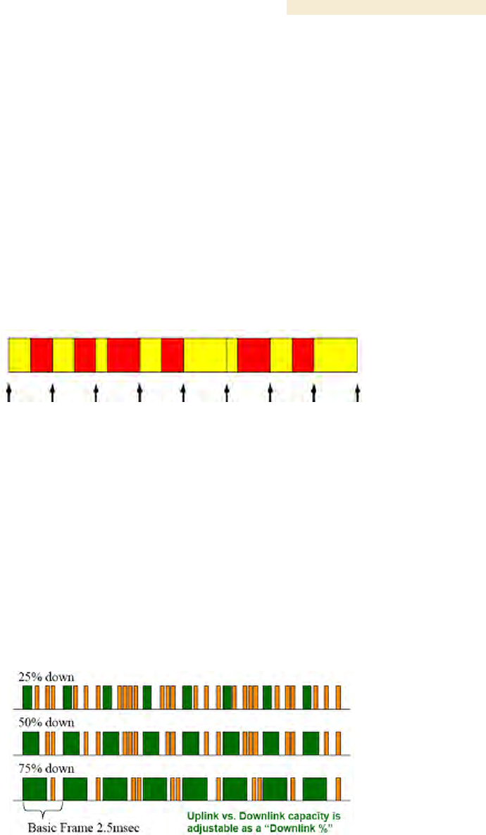
Release 8 Overview of Canopy Networks
March 200 Through Software Release 6.
Issue 2, December 2006 Draft 2 for Regulatory Review 85
7.1.4 Media Access Control and AP Capacity
Regardless of whether the maximum number of SMs (200) all request service at the
same time, the reservation Media Access Control (MAC) system allows the AP to give a
reservation slot to each SM that requests service.
Regardless of the distance between any SM and the AP, the reservation MAC system
ensures that all SM data slots are free of contention. For this reason
◦ all SMs are equally able to compete for uplink and downlink bandwidth.
◦ the capacity of the AP is not degraded by distance from the SMs.
7.1.5 Canopy Slot Usage
The frame illustrated in Figure 22 shows both packet fragments (yellow) and unused slot
space (red) typical of uplink traffic. Packet sizes smaller than 64 bytes cause unused slot
spaces.
Figure 22: Uplink data slot usage
The following statistics apply to Canopy frame slot usage:
◦ Slot size is 64 bytes.
◦ The optimum Ethernet packet size is 1518 bytes.
◦ The maximum downlink throughput for one AP to one SM is 1800 packets per
second (pps).
◦ The maximum uplink throughput for one AP to one SM is 300 pps.
◦ The maximum backhaul throughput is 3000 pps.
7.1.6 Data Transfer Capacity
Canopy modules use Time Division Duplex (TDD) on a common frequency to divide
frames for uplink (orange) and downlink (green) usage, as shown in Figure 23.
Figure 23: TDD dividing Canopy frames
7.1.7 Maximum Information Rate (MIR) Parameters
Canopy point-to-multipoint links use the following four MIR parameters for bandwidth
management:

Overview of Canopy Networks Release 8
86 Draft 2 for Regulatory Review Issue 2, December 2006
◦ Sustained Uplink Data Rate (kbps)
◦ Uplink Burst Allocation (kb)
◦ Sustained Downlink Data Rate (kbps)
◦ Downlink Burst Allocation (kb)
You can independently set each of these parameters per AP or per SM.
Token Bucket Algorithm
The Canopy software uses a token bucket algorithm that
◦ stores credits (tokens) for the SM to spend on bandwidth for reception or
transmission.
◦ drains tokens during reception or transmission.
◦ refills with tokens at the sustained rate set by the network operator.
For each token, the SM can send toward the network in the uplink (or the AP can send
toward the SM in the downlink) an equivalent number of kilobits. Two buckets determine
the permitted throughput: one in the SM for uplink and one in the AP for downlink.
The applicable set of Uplink Burst Allocation and Downlink Burst Allocation
parameters determine the number of tokens that can fill each bucket. When the SM
transmits (or the AP transmits) a packet, the equivalent number of tokens is removed
from the uplink (or downlink) bucket.
Except when full, the bucket is continuously being refilled with tokens at rates that the
applicable set of Sustained Uplink Data Rate and Sustained Downlink Data Rate
parameters specify. The bucket often drains at a rate that is much faster than the
sustained data rate but can refill at only the sustained data rate. Thus, the effects of the
allocation and rate parameters on packet delay are as follows:
◦ the burst allocation affects how many kilobits are processed before packet delay
is imposed.
◦ the sustained data rate affects the packet delay that is imposed.
Which set of these MIR parameters are applicable depends on the interactions of other
parameter values. These interactions are described under Setting the Configuration
Source on Page 292. Also, where the Configuration Source parameter setting in the AP
specifies that BAM values should be used, they are used only if Prizm is configured to
send the values that it stores for the MIR parameters.
MIR Data Entry Checking
Uplink and downlink MIR is enforced as shown in Figure 24.
NOTE:
In these figures, entry refers to the setting in the data rate parameter, not the
burst allocation parameter.

Release 8 Overview of Canopy Networks
March 200 Through Software Release 6.
Issue 2, December 2006 Draft 2 for Regulatory Review 87
uplink cap enforced =
uplink entry x aggregate cap for the SM
uplink entry + downlink entry
downlink cap enforced =
downlink entry x aggregate cap for the SM
uplink entry + downlink entry
Figure 24: Uplink and downlink rate caps adjusted to apply aggregate cap
For example, in the Canopy SM, if you set the Sustained Uplink Data Rate parameter to
2,000 kbps and the Sustained Downlink Data Rate parameter to 10,000 kbps, then the
uplink and downlink MIR that will be enforced for the SM can be calculated as shown in
Figure 25.
uplink cap enforced =
2,000 kbps x 7,000 kbps
2,000 kbps + 10,000 kbps
= 1,167 kbps
downlink cap enforced =
10,000 kbps x 7,000 kbps
2,000 kbps + 10,000 kbps
= 5,833 kbps
Figure 25: Uplink and downlink rate cap adjustment example
In this example case, the derived 1,167-kbps uplink and 5,833-kbps downlink MIR sum to
the fixed 7,000-kbps aggregate cap of the Canopy SM.
7.1.8 Committed Information Rate
The Committed Information Rate (CIR) capability feature enables the service provider to
guarantee to any subscriber that bandwidth will never decrease to below a specified
minimum, unless CIR is oversubscribed. Bandwidth can be, and typically will be, higher
than the minimum, but this guarantee helps the WISP to attract and retain subscribers.
In BAM Release 2.1 and in Prizm Release 2.0, CIR configuration is supported as follows:
◦ The GUI allows you to view and change CIR configuration parameters per SM.
◦ When an SM successfully registers and authenticates, if BAM or Prizm has CIR
configuration data for the SM, then messages make the CIR configuration
available to the SM, depending on the Configuration Source setting. (See Setting
the Configuration Source on Page 292.)
◦ The operator can disable the CIR feature in the SM without deleting the CIR
configuration data.

Overview of Canopy Networks Release 8
88 Draft 2 for Regulatory Review Issue 2, December 2006
7.1.9 Bandwidth from the SM Perspective
In the Canopy SM, normal web browsing, e-mail, small file transfers, and short streaming
video are rarely rate limited with practical bandwidth management (QoS) settings. When
the SM processes large downloads such as software upgrades and long streaming video
or a series of medium-size downloads, the bucket rapidly drains, the burst limit is
reached, and some packets are delayed. The subscriber experience is more affected in
cases where the traffic is more latency sensitive.
Example download times for various arbitrary tiers of service are shown in Table 60 on
Page 384 and Table 61 on Page 385.
7.1.10 Interaction of Burst Allocation and Sustained Data Rate Settings
If the Burst Allocation is set to 1200 kb and the Sustained Data Rate is set to 128 kbps, a
data burst of 1000 kb is transmitted at full speed because the Burst Allocation is set high
enough. After the burst, the bucket experiences a significant refill at the Sustained Data
Rate. This configuration uses the advantage of the settable Burst Allocation.
If both the Burst Allocation and the Sustained Data Rate are set to 128 kb, a burst is
limited to the Burst Allocation value. This configuration does not take advantage of the
settable Burst Allocation.
If the Burst Allocation is set to 128 kb and the Sustained Data Rate is set to 256 kbps, the
actual rate will be the burst allocation (but in kbps). As above, this configuration does not
take advantage of the settable Burst Allocation.
7.1.11 High-priority Bandwidth
To support low-latency traffic such as VoIP (Voice over IP) or video, the Canopy system
implements a high-priority channel. This channel does not affect the inherent latencies in
the Canopy system but allows high-priority traffic to be immediately served. The high-
priority pipe separates low-latency traffic from traffic that is latency tolerant, such as
standard web traffic and file downloads.
A Canopy module prioritizes traffic by
◦ reading the Low Latency bit (Bit 3) in the IPv4 Type of Service (ToS) byte in a
received packet.
◦ reading the 802.1p field of the 802.1Q header in a received packet, where VLAN
is enabled on the module.
◦ comparing the 6-bit Differentiated Services Code Point (DSCP) field in the ToS
byte of a received packet to a corresponding value in the DiffServe tab of the
Configuration page of the module.
Low Latency Bit
Bit 3 is set by a device outside the Canopy system. In the uplink frame, the SM monitors
Bit 3. If this bit is set, then
◦ the SM prioritizes this traffic in its high-priority queue according to AP
configuration settings for the high-priority channel.
◦ the system sends the packet on the high-priority channel and services this
channel before any normal traffic.
802.1P Field
See Priority on VLANs (802.1p) on Page 166.

Release 8 Overview of Canopy Networks
March 200 Through Software Release 6.
Issue 2, December 2006 Draft 2 for Regulatory Review 89
DSCP Field
Like Bit 3 of the original IPv4 ToS byte, the DSCP field (Bits 0 through 5) in the redefined
ToS byte is set by a device outside the Canopy system. A packets contains no flag that
indicates whether the encoding is for the Low Latency bit or the DSCP field. For this
reason, you must ensure that all elements in your trusted domain, including routers and
endpoints, set and read the ToS byte with the same scheme.
Canopy modules monitor ToS bytes with DSCP fields, but with the following differences:
◦ The 6-bit length of the field allows it to specify one of 64 service differentiations.
◦ These correlate to 64 individual (CodePoint) parameters in the DiffServe tab of
the Configuration page.
◦ Per RFC 2474, 3 of these 64 are preset and cannot be changed. (See
http://www.faqs.org/rfcs/rfc1902.html.)
◦ For any or all of the remaining 61 CodePoint parameters, you can specify a value
of
− 0 through 3 for low-priority handling.
− 4 through 7 for high-priority handling.
RECOMMENDATION:
Ensure that your Differentiated Services domain boundary nodes mark any
entering packet, as needed, so that it specifies the appropriate Code Point for
that traffic and domain. This prevents theft of service level.
An example of the DiffServe tab in the Configuration page and parameter descriptions
are provided under DiffServe Tab of the AP on Page 256. This tab and its rules are
identical from module type to module type in Canopy. However, any of the 61
configurable Code Points can be set to a different value from module to module, thus
defining unique per-hop behavior for some traffic.
This tab in the AP and BHM sets the priorities for the various packets in the downstream
(sent from the public network). This tab in the SM and BHS sets the priorities for the
various packets in the upstream (sent to the public network).
Typically in the Canopy network, some SMs attach to older devices that use the ToS byte
as originally formatted, and others to newer devices that use the DSCP field. The default
values in the DiffServe tab allow your modules to prioritize traffic from the older devices
roughly the same as they traditionally have. However, these default values may result in
more high-priority traffic as DSCP fields from the newer devices are read and handled.
So, after making any changes in the DiffServe tab, carefully monitor the high-priority
channel for high packet rates
◦ in SMs that you have identified as those to initially set and watch.
◦ across your Canopy network when you have broadly implemented Code Point
values, such as via SNMP.
The standard channel in Canopy PTMP communications is illustrated in Figure 26.
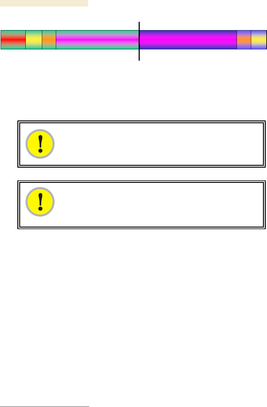
Overview of Canopy Networks Release 8
90 Draft 2 for Regulatory Review Issue 2, December 2006
Con-
trol
Beacon Data
AP Transmit (Downlink ) AP Receive (Uplink )
DataAck
Con-
trol Ack Con-
trol
Beacon Data
AP Transmit (Downlink ) AP Receive (Uplink )
DataAck
Con-
trol Ack
Figure 26: Canopy channel, 75% downlink, 0% high priority in uplink
7.1.12 Hardware Scheduling
Canopy Release 8 supports only hardware scheduling. Hardware scheduling always
sends high-priority traffic first, even to the exclusion of other traffic.
IMPORTANT!
The number of channels available to the AP is reduced by the number of SMs
configured for the high-priority channel. With this feature enabled on all SMs, an
AP can support only 100 SMs (instead of 200).
IMPORTANT!
In a Canopy BH link with Canopy T1/E1 Multiplexers, the BHs must be
configured for an uplink/downlink ratio of 50% uplink/50% downlink. The Canopy
T1/E1 Multiplexers are full duplex.
Canopy Release 8 requires APs, BHs, and AES SMs to be Series P9 or later hardware.3
The characteristics of hardware scheduling in a Canopy sector are summarized in
Table 25.
3 See Designations for Hardware in Radios on Page 367.

Release 8 Overview of Canopy Networks
March 200 Through Software Release 6.
Issue 2, December 2006 Draft 2 for Regulatory Review 91
Table 25: Characteristics of hardware scheduling
Category
Factor
Treatment
Aggregate throughput, less
additional overhead
14 Mbps
Throughput
ACK slots in downlink used
for data except when request
for uplink is present
Yes
Number of frames required
for the scheduling process
1
Round-trip latency1
≈ 6 ms
Latency
AP broadcast the download
schedule
No
Allocation for uplink high-
priority traffic on amount of
high-priority traffic
Dynamic, based
on amount of
high-priority
traffic
Allocation for downlink high-
priority traffic on amount of
high-priority traffic
Dynamic, based
on amount of
high-priority
traffic
High-priority
Channel
Order of transmission
1. CIR high-priority
2. CIR low-priority
3. Other high-priority
4. Other low-priority
Transmit
Frame
Spreading
Support for Transmit Frame
Spreading feature
In Release 7.0 and
later
CIR
Capability
In all releases
NOTES:
1. For 2.4- and 5.n-GHz modules.
CAUTION!
Power requirements for modules that run hardware scheduling affect the
recommended maximums for power cord length feeding the CMMmicro. See
Table 55 on Page 344. However, the requirements do not affect the maximums
for the CMM2.
Packets that have a priority of 4 to 7 in either the DSCP or a VLAN 802.1p tag are
automatically sent on the high-priority channel, but only where the high-priority channel is
enabled.
7.1.13 2X Operation
A General tab option in both Advantage SMs and some Canopy SMs provides double the
aggregate throughput for SMs that are nearer than half of the distance range from the AP

Overview of Canopy Networks Release 8
92 Draft 2 for Regulatory Review Issue 2, December 2006
(the nearest one-fourth of the SMs in the sector). The requirements of this feature are as
follows:
◦ The AP must be an Advantage AP.
◦ The SM must be near the AP, as described above.
◦ The SM must be of the P9 hardware series and enabled for hardware
scheduling. See Designations for Hardware on Page 367.
◦ The 2X Rate parameter in the SM must be set to enabled. This is the default
setting.
◦ The amount of noise and multipath must be low enough to allow the receiver in
the 6-dB less sensitive (2X) state to maintain a high carrier-to-interference (C/I)
ratio.
The flexibility of this feature is as follows:
◦ At the time of registration, signaling is at the 1X rate. However, if the above
requirements are all met, then the SM switches to 2X.
◦ Thereafter, whenever RF conditions are unfavorable for 2X operation, the SM
switches to 1X. When favorable RF conditions allow, the SM switches back to
2X, if user data is present at that time.
◦ Similarly, whenever no user data is present, the SM switches to 1X. When user
data flow resumes, the SM switches back to 2X, if RF conditions allow.
◦ Both links for the SM (uplink and downlink) are independent for this feature.
(One can be operating at 2X operation while the other is operating at 1X.)
◦ Other SMs in the sector can be communicating with the AP at the other
modulation rate.
◦ Although subscribers with Canopy SMs realize higher bursts, and subscribers
with Advantage SMs realize both higher burst and higher sustained throughput,
the network operator realizes higher sector throughput capacity in the AP.
The effect of 2X operation on aggregate throughput for the SM is indicated in Table 26.
Table 26: Effect of 2X operation on throughput for the SM
Typical Aggregate Rates1
Type of SM
Sustained2
Burst2
900 MHz3
4 Mbps
4 Mbps
Advantage
Any other frequency
band range
14 Mbps
14 Mbps
Canopy P9
Any frequency band
range except 900 MHz
7 Mbps
14 Mbps
NOTES:
1. Subject to competition among all SMs in the sector.
2. Can be less if limited by the value of Downlink Data set in the
Radio tab of the Configuration page in the AP.
3. All 900-MHz modules are Advantage.

Release 8 Overview of Canopy Networks
March 200 Through Software Release 6.
Issue 2, December 2006 Draft 2 for Regulatory Review 93
Competition for Bandwidth
When multiple SMs vie for bandwidth, the AP divides its bandwidth among them,
considering their effective CIR and MIR values. However, 2X operation uses bandwidth
twice as efficiently as 1X, even where MIR values apply. This is because, in 2X
operation, the modules transmit their data in 4-level frequency shift keying (FSK), not
2-level as they would in 1X operation. This moves twice the data per slot. Thus, for the
sum of all bandwidth that 2X-eligible customers use, the bandwidth available to the
remaining customers increases by half of that sum when these eligible customers are
transmitting and receiving in 2X operation.
Engineering for 2X Operation
The following priorities should guide your implementation of 2X operation:
◦ In the near half of the distance range of the AP
− identify the customers who use the most bandwidth.
− enable their SMs first for 2X operation.
◦ When you have deployable Canopy P7 and P8 SMs, do not deploy Canopy
Advantage SMs or Canopy P9 SMs beyond half the distance range of the AP.
At this distance, steady and reliable 2X operation typically is not achievable.
Deploy the Canopy P7 and P8 SMs here.
◦ Wherever practical, implement 25 MHz of channel separation for 2X operation.
Checking Link Efficiencies in 2X Operation
Unlike in 1X operation, efficiencies below 90% on the Link Capacity Test tab in the Tools
web page of the SM do not necessarily indicate a poor quality link. Efficiency of 45% in
2X operation is equivalent to efficiency of 90% in 1X. If you read efficiency between 45%
and 90%, check the status of 2X operation (as described below) to confirm that the link is
operating at 2X.
Since received signal strength typically varies over time, you should perform link tests at
various times of day and on various days of the week. Efficiencies should consistently be
45% or greater for 2X operation. Where readings are lower, you are unlikely to solve the
RF problem by enabling 1X operation. (For example, if you read 40% at 2X, you can
expect 80% at 1X.) In these cases, you may be able to achieve better efficiencies by re-
aiming the SM, mounting it elsewhere, or retrofitting it with a reflector dish.
Checking the Status of 2X Operation
The Session Status tab in the Home page of the AP provides operation status information
about each SM-to-AP link. Under the MAC address of each SM, the data in this tab
includes a line such as the following:
RATE : VC 19 Rate 2X/2X VC 255 Rate 2X/1X
Interpret this information is as follows:
◦ VC means virtual channel. If one VC is displayed, the high-priority channel is
disabled. If two are displayed, the high-priority channel is enabled and is using
the higher number VC (255 in the above example).
◦ 2X/2X indicates that the SM-to-AP link is in 2X operation.
◦ 2X/1X indicates that the SM is capable of 2X operation but the SM-to-AP link is in
1X operation. This can be for either of the following reasons:
− The SM has not sent data on the channel yet.

Overview of Canopy Networks Release 8
94 Draft 2 for Regulatory Review Issue 2, December 2006
− The received signal does not support 2X operation.
◦ 1X/1X indicates that the SM is capable of only 1X operation. This can be for
either of the following reasons:
− The SM does not support 2X operation (SM is of the hardware series P7
or P8).
− The 2X Rate parameter is disabled in the General tab of the Configuration
page in the SM.
CAUTION!
2X operation requires approximately 3 to 5% more power than 1X operation.
This additional power affects the recommended maximum for power cord length
feeding the CMMmicro. See Table 55 on Page 344. However, 2X operation
does not affect the maximums for the CMM2.
Disabling 2X Operation
Disabling 2X operation for an SM can be helpful for alignment, troubleshooting, or
preventing frequent automatic switches between 2X and 1X, where RF conditions are
only marginally favorable to 2X. The ability to disable 2X for an SM is inherent since the
2X Operation feature was introduced.
Disabling 2X operation for a sector can be helpful for identifying a baseline for 1X-to-2X
comparison, broader troubleshooting activities, or forcing all SMs to 1X rather than
disabling 2X in each SM. Release 8 provides a 2X Rate parameter in the General tab of
the Configuration page in the AP:
◦ If you click Disable, then Save Changes and Reboot, 2X operation is disabled
for the sector, regardless of the 2X Rate setting in each SM.
◦ If you later click Enable, then Save Changes and Reboot, 2X operation is
enabled in the sector for SMs with 2X Rate enabled on their
Configuration>General page. SMs with 2X Rate disabled on their
Configuration>General page (or P7 or P8 SMs that don’t support 2X Rate) will
only operate at 1X.
7.2 UNDERSTANDING SYNCHRONIZATION
The system usesTime Division Duplexing (TDD) - one channel alternately transmits and
receives - rather than using one channel for transmitting and a second channel for
receiving. To accomplish TDD, the AP must provide sync to its SMs – it must keep them
in sync. Furthermore, collocated APs must be synced together - an unsynchronized AP
that transmits during the receive cycle of a collocated AP can prevent that second AP
from being able to decode the signals from its SMs. In addition, across a geographical
area, APs that can “hear” each other benefit from using a common sync to further reduce
self-interference within the network.
7.2.1 GPS Synchronization
The Navigation Satellite Timing and Ranging (NAVSTAR) Global Positioning System
(GPS) uses 24 satellites to relay information for precise derivation of position and time.
The Canopy Cluster Management Module (CMM) contains a Motorola Oncore GPS
Receiver. The CMM is a critical element in the operation of the Canopy system. At one

Release 8 Overview of Canopy Networks
March 200 Through Software Release 6.
Issue 2, December 2006 Draft 2 for Regulatory Review 95
AP cluster site or throughout an entire wireless system, the CMM provides a GPS timing
pulse to each module, synchronizing the network transmission cycles.
The Oncore GPS Receiver tracks eight or more satellites. The CMM uses the signal from
at least four of these satellites to generate a one-second interval clock that has a rise
time of 100 nsec. This clock directly synchronizes APs and BHMs which, in turn,
synchronize the SMs and BHSs in the Canopy network.
The Oncore GPS Receiver also provides
◦ the latitude and longitude of the GPS antenna (collocated with the CMM)
◦ the number of satellites that are being tracked
◦ the number of satellites that are available
◦ the date
◦ the time in Universal Coordinated Time (UCT)
◦ the altitude of the GPS antenna
◦ other information that can be used to diagnose network problems.
Alternative to GPS Sync
A Canopy link can operate without GPS sync, but cannot operate without sync. The
alternative to GPS sync is to configure the AP or BHM in the link to generate a sync pulse
to pass to the SM or BHS, respectively. Depending on the RF environment in which the
link operates, this latter alternative may or may not be plausible.
For example, in Figure 27, AP4
◦ is not synchronized with any of the other APs.
◦ is transmitting nearby the other APs while they are expecting to receive SM
transmissions from a maximum distance.
Figure 27: One unsynchronized AP in cluster
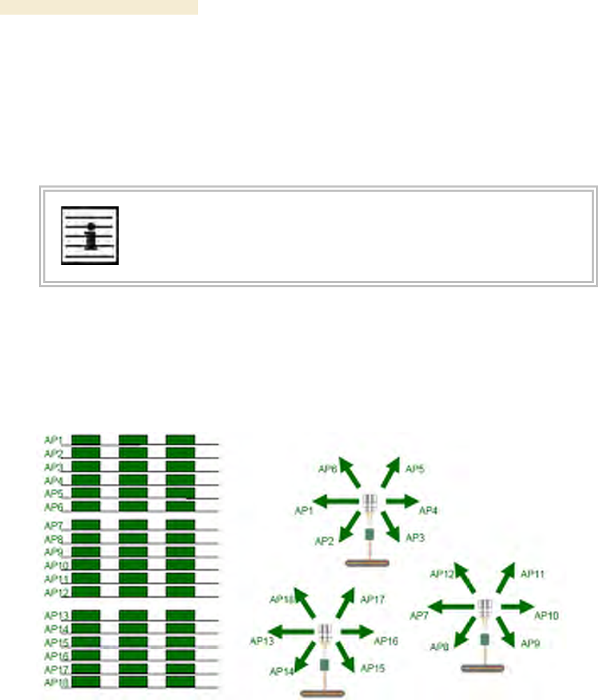
Overview of Canopy Networks Release 8
96 Draft 2 for Regulatory Review Issue 2, December 2006
The result is self-interference. In this scenario, the self-interference can be avoided only
by synchronizing the TDD transmit cycles of all APs that operate in the same frequency
band.
An AP that is isolated by at least 5 miles (8 km) from any other Canopy equipment, or a
BHM in an isolated standalone BH link can generate and pass sync pulse without GPS
timing and not risk that interference will result from the generated sync. In any other type
of Canopy link, sync should be derived from GPS timing.
NOTE:
The OFDM Series BHMs generate their own sync. For more information about
these modules, see the user guides that support them. Titles are listed under
Products Not Covered by This User Guide on Page 34.
Advantage of GPS Sync
Although the embedded timing generation capability of the Canopy AP and BHM keeps a
precise clock, no trigger exists to start the clock at the same moment in each AP of a
cluster. So, the individual AP can synchronize communications between itself and
registered SMs, but cannot synchronize itself with other Canopy modules, except by GPS
timing (shown in Figure 28).
Figure 28: GPS timing throughout the Canopy network
7.2.2 Passing Sync in a Single Hop
Network sync can be passed in a single hop in the following network designs:
◦ Design 1
1. A CMM provides sync to a collocated AP.
2. This AP sends the sync over the air to SMs.
◦ Design 2
1. A CMM provides sync to a collocated BH timing master.
2. This BH timing master sends the sync over the air to a BH timing slave.
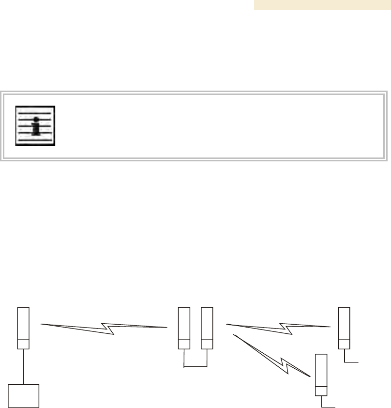
Release 8 Overview of Canopy Networks
March 200 Through Software Release 6.
Issue 2, December 2006 Draft 2 for Regulatory Review 97
7.2.3 Passing Sync in an Additional Hop
Network sync can be extended by one additional link in any of the following network
designs:
NOTE:
In each of these following designs, Link 2 is not on the same frequency band as
Link 4. (For example, Link 2 may be a 5.2-GHz link while Link 4 is a 5.7- or 2.4-
GHz link.)
◦ Design 3
1. A CMM provides sync to a collocated AP.
2. This AP sends the sync over the air to an SM.
3. This SM delivers the sync to a collocated AP.
4. This AP passes the sync in the additional link over the air to SMs.
This design is illustrated in Figure 29.
CMM
AP APSM SM
SM
2
1
3
4
4
Figure 29: Additional link to extend network sync, Design 3
◦ Design 4
1. A CMM provides sync to a collocated AP.
2. This AP sends the sync over the air to an SM.
3. This SM delivers the sync to a collocated BHM.
4. This BHM passes the sync in the additional link over the air to a BHS.
This design is illustrated in Figure 30.
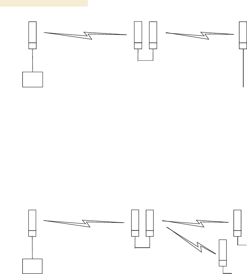
Overview of Canopy Networks Release 8
98 Draft 2 for Regulatory Review Issue 2, December 2006
CMM
BH
-M-
AP BH
-S-
SM
2
1
3
4
Figure 30: Additional link to extend network sync, Design 4
◦ Design 5
1. A CMM provides sync to a collocated BHM or the BHM generates timing.
2. This BHM sends the sync over the air to a BHS.
3. This BHS delivers the sync to a collocated AP.
4. This AP passes the sync in the additional link over the air to SMs.
This design is illustrated in Figure 31.
CMM
BH
-M- AP
BH
-S- SM
SM
2
1
3
4
4
Figure 31: Additional link to extend network sync, Design 5
Wiring and configuration information for this sync extension is described under Wiring to
Extend Network Sync on Page 369.
All Canopy radios support the remote AP functionality. The BHS and the SM can reliably
pass the sync pulse, and the BHM and AP can reliably receive it. The sync is passed in a
cable that connects Pins 1 and 6 of the RJ-11 timing ports of the two modules. (The sync
cable is described under Cables on Page 59.) When you connect modules in this way,
you must also adjust configuration parameters to ensure that
◦ the AP is set to properly receive sync.
◦ the SM will not propagate sync to the AP if the SM itself ceases to receive sync.

Release 8 Overview of Canopy Networks
March 200 Through Software Release 6.
Issue 2, December 2006 Draft 2 for Regulatory Review 99
8 MEETING LINK REQUIREMENTS
8.1 AP-SM LINKS
APs communicate with SMs using a point-to-multipoint protocol. An AP-SM link has lower
throughput and higher latency than a backhaul link for two reasons:
◦ Many endpoints are involved.
◦ The bandwidth request and reservation process consumes bandwidth.
In the 900-MHz frequency band range, round-trip latency is typically
◦ 40 msec with software scheduling.
◦ 15 msec with hardware scheduling.
In all other Canopy frequency band ranges, round-trip latency is typically
◦ 15 msec with software scheduling.
◦ 6 msec with hardware scheduling.
At range settings of greater than 40 miles (64 km) in the 900-MHz AP, more time elapses
between transmit and receive cycles to compensate for greater air delay. In each frame,
this reduces the number of data slots, which slightly reduces the aggregate throughput of
the link. However, the throughput is as predictable as in other Canopy point-to-multipoint
links.
Throughput is a factor of the Max Range parameter in the AP and is effective for all SMs,
regardless of their distance from the AP. Throughput includes all downlink data to all SMs
and all uplink data from all SMs that link to the AP. For throughput with hardware
scheduling, see Table 14 on Page 64.
End user perspective of throughput is based on both bandwidth in the sending direction
and the return of TCP acknowledgement packets in the other. Where sufficient downlink
bandwidth exists to support downlink traffic and overhead, transient traffic congestion in
the uplink can cause some TCP acknowledgement packets to be dropped, and the end
user to perceive a reduction in throughput. This can also occur with sufficient uplink
bandwidth and dropping acknowledgment packets in the downlink.
However, a Canopy network operator can optionally enable the Prioritize TCP ACK
parameter in the AP and BHM, giving these packets priority over other packet types.
This results in fewer of them being dropped.
The effects of changing network conditions on PTMP throughput are indicated in
Table 27.

Overview of Canopy Networks Release 8
100 Draft 2 for Regulatory Review Issue 2, December 2006
Table 27: Effects of network conditions on PTMP throughput
Changing Network Condition
Effect on AP Aggregate Throughput
Increasing the Max Range
parameter setting1 in the AP
somewhat decreased2
Increasing the number of SMs that
register in the AP
Increase in downlink traffic
Increase in uplink traffic
no effect
Increasing the average bandwidth
allotted to the SMs that register in
the AP
no effect, even when the additional
bandwidth is used.
NOTES:
1. For non 900-MHz APs, the AP accepts a Max Range value of up to 30
miles (48 km). See Max Range on Page 242.
2. To avoid a decrease of unnecessary proportion, set to not much further
than the distance between the AP and the furthest SM that registers in
the AP.
A comparison of SM products in link with a Canopy Advantage AP is shown in Table 28.
Table 28: Comparison of SM products with Canopy Advantage AP
Product
Maximum Sustained
Aggregate
Throughput
to a Single SM
Burst
Cap on
Committed
Information
Rate
Upgradability
VoIP
Channels
Supported
Canopy Advantage SM
14 Mbps
14 Mb
none
none
multiple
Canopy SM
7 Mbps
14 Mb
none
to Advantage SM
capabilities
multiple
Canopy Lite SM as
purchased
512 kbps
768 kb
100 kbps
to 1, 2, 4, or
7 Mbps
1
Canopy Lite SM
upgraded to 1 Mbps
1 Mbps
1.5 Mb
100 kbps
none
1
Canopy Lite SM
upgraded to 2 Mbps
2 Mbps
3 Mb
100 kbps
none
1
Canopy Lite SM
upgraded to 4 Mbps
4 Mbps
7 Mb
200 kbps
none
2
Canopy Lite SM
upgraded to 7 Mbps
7 Mbps
7 Mb
200 kbps
none
2
8.2 BH-BH LINKS
Canopy BHs communicate with each other using a point-to-point protocol. This point-to-
point protocol uses a 2.5-msec frame. A BH link has higher throughput and lower latency
(typically 5 msec, 2.5 msec in each direction) for two reasons:
◦ Only two endpoints are involved.