Motorola Solutions 89FT7623 5400xxyyzzab User Manual Operations guide pt 2a
Motorola Solutions, Inc. 5400xxyyzzab Operations guide pt 2a
Contents
Operations guide pt 2a
Release 8 Installation and Configuration Guide
Issue 2, December 2006 Draft 2 for Regulatory Review 251
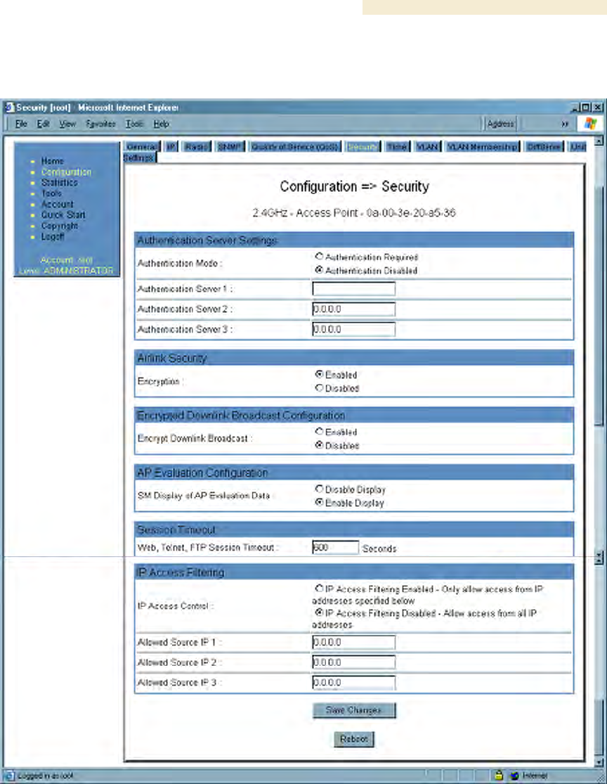
18.1.6 Security Tab of the AP
An example of the Security tab of the AP is displayed in Figure 86.
Figure 86: Security tab of AP, example
In the Security tab of the AP, you may set the following parameters.
Authentication Mode
If the AP has authentication capability, then you can use this field to select from among
the following authentication modes:
◦ Authentication Disabled—the AP requires no SMs to authenticate.

Installation and Configuration Guide Release 8
252 Draft 2 for Regulatory Review Issue 2, December 2006
◦ Authentication Required—the AP requires any SM that attempts registration to
be authenticated in BAM or Prizm before registration.
If the AP does not have authentication capability, then this parameter displays
Authentication Not Available.
Authentication Server 1 to 3
If either BAM or the BAM subsystem in Prizm is implemented and the AP has
authentication capability, enter the IP address of one or more BAM servers that perform
authentication for SMs registered to this AP. Enter these in order of primary, secondary,
then tertiary.
Encryption
Specify the type of air link security to apply to this AP:
◦ Encryption Disabled provides no encryption on the air link. This is the default
mode.
◦ Encryption Enabled provides encryption, using a factory-programmed secret
key that is unique for each module.
Encrypt Downlink Broadcast
When Encryption Enabled is selected in the Airlink Security parameter (described
above) and Enable is selected in the Encrypt Downlink Broadcast parameter, the AP
encrypts downlink broadcast packets as
◦ DES where the AP is DES capable.
◦ AES where the AP is AES capable.
For more information about the Encrypt Downlink Broadcast feature, see Encrypting
Downlink Broadcasts on Page 380.
SM Display of AP Evaluation Data
You can use this field to suppress the display of data about this AP on the AP Evaluation
tab of the Tools page in all SMs that register.
Web, Telnet, FTP Session Timeout
Enter the expiry in seconds for remote management sessions via HTTP, telnet, or ftp
access to the AP.
IP Access Control
You can permit access to the AP from any IP address (IP Access Filtering Disabled) or
limit it to access from only one, two, or three IP addresses that you specify (IP Access
Filtering Enabled). If you select IP Access Filtering Enabled, then you must populate
at least one of the three Allowed Source IP parameters or have no access permitted
from any IP address, including access and management by Prizm.
Allowed Source IP 1 to 3
If you selected IP Access Filtering Enabled for the IP Access Control parameter, then
you must populate at least one of the three Allowed Source IP parameters or have no
access permitted to the AP from any IP address. You may populate as many as all three.
If you selected IP Access Filtering Disabled for the IP Access Control parameter, then
no entries in this parameter are read, and access from all IP addresses is permitted.
Release 8 Installation and Configuration Guide
Issue 2, December 2006 Draft 2 for Regulatory Review 253
The Security tab of the AP also provides the following buttons.
Save Changes
When you click this button, any changes that you made on this tab are recorded in flash
memory. However, these changes do not apply until the next reboot of the module.
Reboot
When you click this button
1. the module reboots.
2. any changes that you saved by a click of the Save Changes button are
implemented.
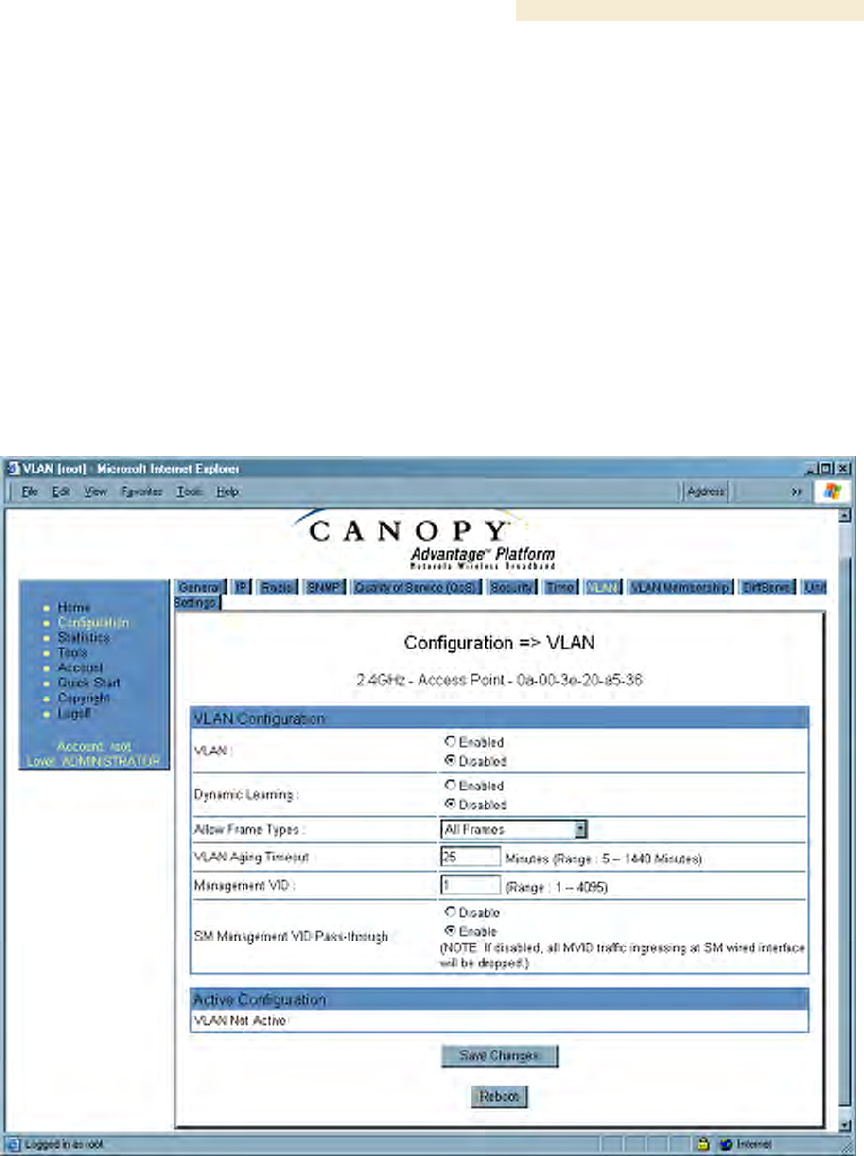
18.1.7 VLAN Tab of the AP
An example of the AP VLAN tab is displayed in Figure 87.
Figure 87: VLAN tab of AP, example
In the VLAN tab of the AP, you may set the following parameters.
VLAN
Specify whether VLAN functionality for the AP and all linked SMs should (Enabled) or
should not (Disabled) be allowed. The default value is Disabled.
Installation and Configuration Guide Release 8
254 Draft 2 for Regulatory Review Issue 2, December 2006
Dynamic Learning
Specify whether the AP should (Enabled) or should not (Disabled) add the VLAN IDs
(VIDs) of upstream frames to the VID table. (The AP passes frames with VIDs that are
stored in the table both upstream and downstream.) The default value is Enabled.
Allow Frame Types
Select the type of arriving frames that the AP should tag, using the VID that is stored in
the Untagged Ingress VID parameter. The default value is All Frames.
VLAN Aging Timeout
Specify how long the AP should keep dynamically learned VIDs. The range of values is 5
to 1440 (minutes). The default value is 25 (minutes).
NOTE:
VIDs that you enter for the Management VID and VLAN Membership
parameters do not time out.
Management VID
Enter the VID that the operator wishes to use to communicate with the module manager.
The range of values is 1 to 4095. The default value is 1.
SM Management VID Pass-through
Specify whether to allow the SM (Enable) or the AP (Disable) to control the VLAN
settings of this SM. The default value is Enable.
CAUTION!
Do not set this parameter to Enable where both
◦ a BAM release earlier than 2.1 is implemented.
◦ the Configuration Source parameter in the AP is set to BAM.
This combination causes the SMs to become unmanageable, until you gain
direct access with an override plug and remove this combination from the AP
configuration.
Save Changes
When you click this button, any changes that you made on this tab are recorded in flash
memory. However, these changes do not apply until the next reboot of the module.
Reboot
When you click this button
1. the module reboots.
2. any changes that you saved by a click of the Save Changes button are
implemented.
Release 8 Installation and Configuration Guide
Issue 2, December 2006 Draft 2 for Regulatory Review 255
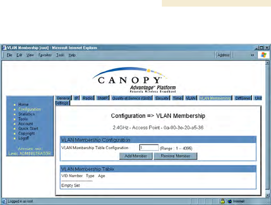
18.1.8 VLAN Membership Tab of the AP
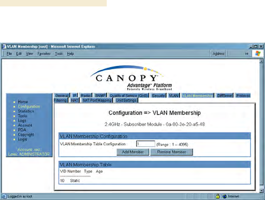
An example of the VLAN Membership tab of the AP is displayed in Figure 88.
Figure 88: VLAN Membership tab of AP, example
You may set the VLAN Membership tab parameter as follows.
VLAN Membership Table Configuration
For each VLAN in which you want the AP to be a member, enter the VLAN ID and then
click the Add Member button. Similarly, for any VLAN in which you want the AP to no
longer be a member, enter the VLAN ID and then click the Remove Member button.
Installation and Configuration Guide Release 8
256 Draft 2 for Regulatory Review Issue 2, December 2006
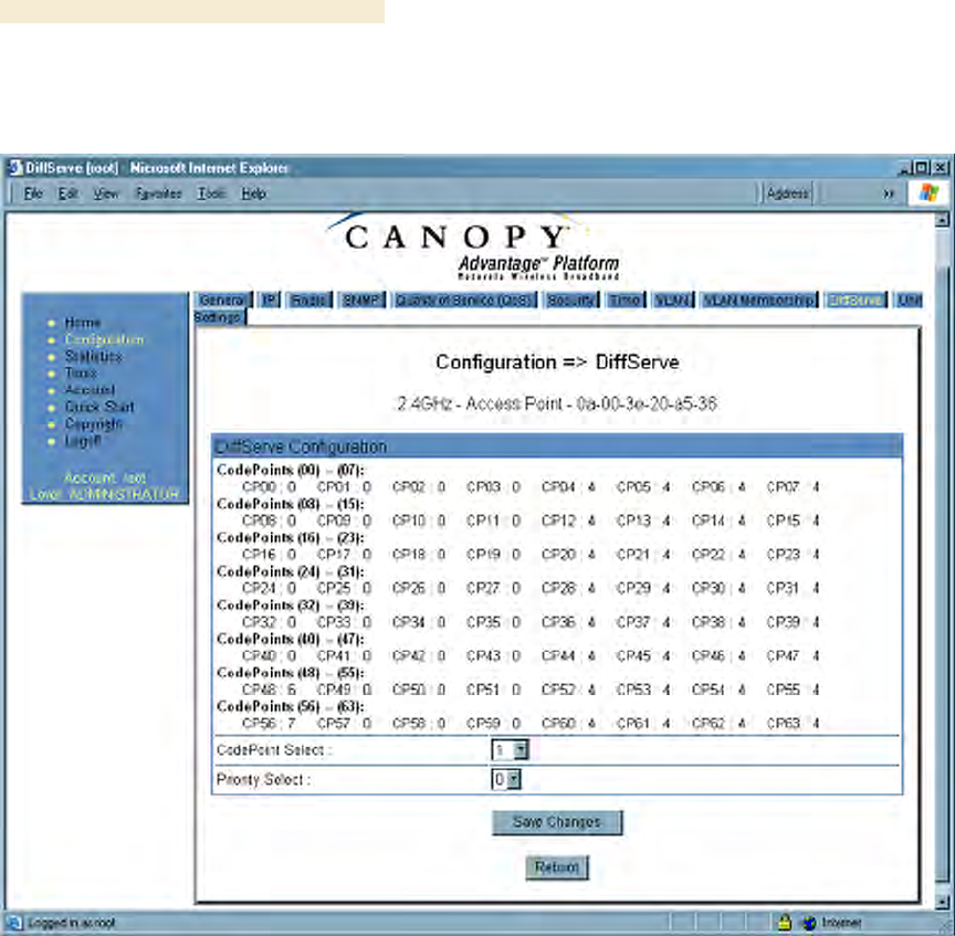
18.1.9 DiffServe Tab of the AP
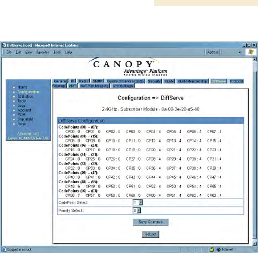
An example of the DiffServe tab of the AP is displayed in Figure 89.
Figure 89: DiffServe tab of AP, example

Release 8 Installation and Configuration Guide
Issue 2, December 2006 Draft 2 for Regulatory Review 257
You may set the following DiffServe tab parameters.
CodePoint 1
through
CodePoint 47
CodePoint 49
through
CodePoint 55
CodePoint 57
through
CodePoint 63
The default priority value for each settable CodePoint is shown in
Figure 119. Priorities of 0 through 3 map to the low-priority channel;
4 through 7 to the high-priority channel. The mappings are the same
as 802.1p VLAN priorities.
Consistent with RFC 2474
◦ CodePoint 0 is predefined to a fixed priority value of 0
(low-priority channel).
◦ CodePoint 48 is predefined to a fixed priority value of 6
(high-priority channel).
◦ CodePoint 56 is predefined to a fixed priority value of 7
(high-priority channel).
You cannot change any of these three fixed priority values. Among
the settable parameters, the priority values (and therefore the
handling of packets in the high- or low-priority channel) are set in
the AP for all downlinks within the sector and in the SM for each
uplink. See DSCP Field on Page 89.
The DiffServe tab also contains the following buttons.
Save Changes
When you click this button, any changes that you made on all tabs are recorded in flash
memory. However, these changes do not apply until the next reboot of the module.
Reboot
When you click this button
1. the module reboots.
2. any changes that you saved by a click of the Save Changes button are
implemented.
Installation and Configuration Guide Release 8
258 Draft 2 for Regulatory Review Issue 2, December 2006
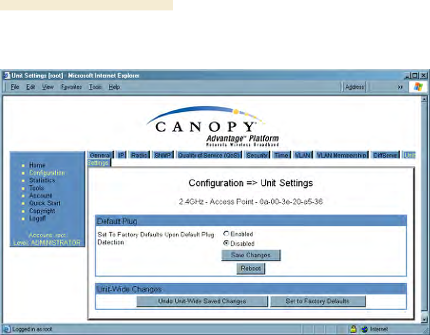
18.1.10 Unit Settings Tab of the AP
An example of the Unit Settings tab of the AP is shown in Figure 90.
Figure 90: Unit Settings tab of AP, example
The Unit Settings tab of the AP contains an option for how the AP should react when it
detects a connected override plug. You may set this option as follows.
Set to Factory Defaults Upon Default Plug Detection
If Enabled is checked, then an override/default plug functions as a default plug. When
the module is rebooted with the plug inserted, it can be accessed at the IP address
169.254.1.1 and no password, and all parameter values are reset to defaults.
A subscriber, technician, or other person who gains physical access to the module and
uses an override/default plug cannot see or learn the settings that were previously
configured in it. When the module is later rebooted with no plug inserted, the module
uses the new values for any parameters that were changed and the default values for
any that were not.
If Disabled is checked, then an override/default plug functions as an override plug. When
the module is rebooted with the plug inserted, it can be accessed at the IP address
169.254.1.1 and no password, and all previously configured parameter values remain
and are displayed. A subscriber, technician, or other person who gains physical access
to the module and uses an override/default plug can see and learn the settings. When the
module is later rebooted with no plug inserted, the module uses the new values for any
parameters that were changed and the previous values for any that were not.
See Overriding Forgotten IP Addresses or Passwords on AP, SM, or BH on Page 375.
The Unit Settings tab also contains the following buttons.

Release 8 Installation and Configuration Guide
Issue 2, December 2006 Draft 2 for Regulatory Review 259
Save Changes
When you click this button, any changes that you made on all tabs are recorded in flash
memory. However, these changes do not apply until the next reboot of the module.
Reboot
When you click this button
1. the module reboots.
2. any changes that you saved by a click of the Save Changes button are
implemented.
Undo Unit-Wide Saved Changes
When you click this button, any changes that you made in any tab but did not commit by
a reboot of the module are undone.
Set to Factory Defaults
When you click this button, all configurable parameters on all tabs are reset to the factory
settings.
18.2 CONFIGURING AN SM FOR THE DESTINATION
If an ADMINISTRATOR-level password has been set in the SM, you must log into the
module before you can configure its parameters. See Managing Module Access by
Passwords on Page 373.
Installation and Configuration Guide Release 8
260 Draft 2 for Regulatory Review Issue 2, December 2006
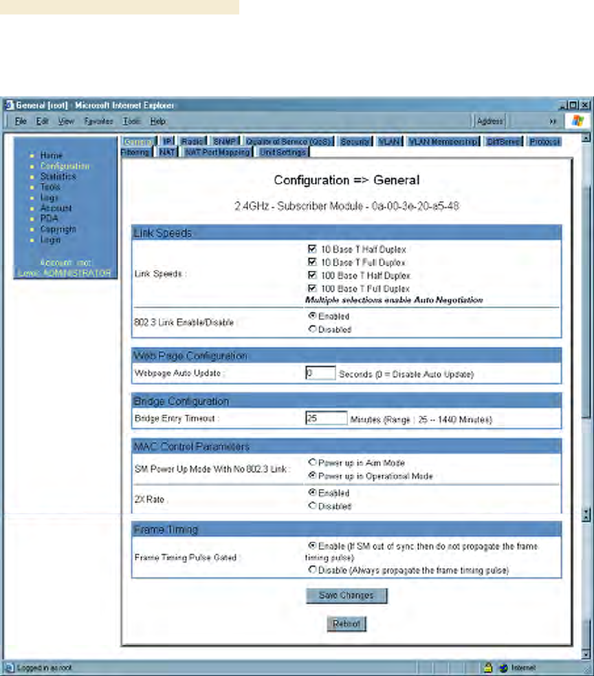
18.2.1 General Tab of the SM
An example of a General tab in the SM is displayed in Figure 91.
Figure 91: General tab of SM, example
In the General tab of the SM, you may set the following parameters.
Link Speeds
Specify the type of link speed for the Ethernet connection. The default for this parameter
is that all speeds are selected. The recommended setting is a single speed selection for
all APs, BHs, and SMs in the operator network.

Release 8 Installation and Configuration Guide
Issue 2, December 2006 Draft 2 for Regulatory Review 261
802.3 Link Enable/Disable
Specify whether to enable or disable Ethernet/802.3 connectivity on the wired port of
the SM. This parameter has no effect on the wireless link. When you select Enable, this
feature allows traffic on the Ethernet/802.3 port. This is the factory default state of the
port. When you select Disable, this feature prevents traffic on the port. Typical cases
of when you may want to select Disable include:
◦ The subscriber is delinquent with payment(s).
◦ You suspect that the subscriber is sending or flooding undesired broadcast
packets into the network, such as when
− a virus is present in the subscriber's computing device.
− the subscriber's home router is improperly configured.
Webpage Auto Update
Enter the frequency (in seconds) for the web browser to automatically refresh the web-
based interface. The default setting is 0. The 0 setting causes the web-based interface to
never be automatically refreshed.
Bridge Entry Timeout
Specify the appropriate bridge timeout for correct network operation with the existing
network infrastructure. Timeout occurs when the AP encounters no activity with the SM
(whose MAC address is the bridge entry) within the interval that this parameter specifies.
The Bridge Entry Timeout should be a longer period than the ARP (Address Resolution
Protocol) cache timeout of the router that feeds the network.
This parameter governs the timeout interval, even if a router in the system has a longer
timeout interval. The default value of this field is 25 minutes.
CAUTION!
An inappropriately low Bridge Entry Timeout setting may lead to temporary
loss of communication with some end users.
SM Power Up Mode With No 802.3 Link
Specify the default mode in which this SM will power up when the SM senses no Ethernet
link. Select either
◦ Power Up in Aim Mode—the SM boots in an aiming mode. When the SM
senses an Ethernet link, this parameter is automatically reset to Power Up in
Operational Mode. When the module senses no Ethernet link within 15 minutes
after power up, the SM carrier shuts off.
◦ Power Up in Operational Mode—the SM boots in Operational mode. The
module attempts registration. Unlike in previous releases, this is the default
selection in Release 8.
2X Rate
Disable this parameter to facilitate initial aiming from the destination. Then see 2X
Operation on Page 91.

Installation and Configuration Guide Release 8
262 Draft 2 for Regulatory Review Issue 2, December 2006
Frame Timing Pulse Gated
If this SM extends the sync pulse to a BH master or an AP, select either
◦ Enable—If this SM loses sync from the AP, then do not propagate a sync pulse
to the BH timing master or other AP. This setting prevents interference in the
event that the SM loses sync.
◦ Disable—If this SM loses sync from the AP, then propagate the sync pulse to the
BH timing master or other AP.
See Wiring to Extend Network Sync on Page 369.
The General tab also contains the following buttons.
Save Changes
When you click this button, any changes that you made on all tabs are recorded in flash
memory. However, these changes do not apply until the next reboot of the module.
Reboot
When you click this button
1. the module reboots.
2. any changes that you saved by a click of the Save Changes button are
implemented.
18.2.2 NAT and IP Tabs of the SM with NAT Disabled
An example of the NAT tab in an SM with NAT disabled is displayed in Figure 92.
Release 8 Installation and Configuration Guide
Issue 2, December 2006 Draft 2 for Regulatory Review 263
Figure 92: NAT tab of SM with NAT disabled, example
This implementation is illustrated in Figure 46 on Page 157. In the NAT tab of an SM with
NAT disabled, you may set the following parameters.

Installation and Configuration Guide Release 8
264 Draft 2 for Regulatory Review Issue 2, December 2006
NAT Enable/Disable
This parameter enables or disabled the Network Address Translation (NAT) feature for
the SM. NAT isolates devices connected to the Ethernet/wired side of an SM from being
seen directly from the wireless side of the SM. With NAT enabled, the SM has an IP
address for transport traffic separate from its address for management, terminates
transport traffic, and allows you to assign a range of IP addresses to devices that are
connected to the Ethernet/wired side of the SM. For further information, see Network
Address Translation (NAT) on Page 156 and NAT and IP Tabs of the SM with NAT
Enabled on Page 268.
NAT Private Network Interface Configuration, IP Address
This parameter is not configurable when NAT is disabled.
NAT Private Network Interface Configuration, Subnet Mask
This parameter is not configurable when NAT is disabled.
DMZ Host Interface Configuration, IP Address
This parameter is not configurable when NAT is disabled.
DMZ Enable
This parameter is not configurable when NAT is disabled.
NAT Public Network Interface Configuration, IP Address
This field displays the IP address for the SM. DHCP Server will not automatically assign
this address when NAT is disabled.
NAT Public Network Interface Configuration, Subnet Mask
This field displays the subnet mask for the SM. DHCP Server will not automatically
assign this address when NAT is disabled.
NAT Public Network Interface Configuration, Gateway IP Address
This field displays the gateway IP address for the SM. DHCP Server will not automatically
assign this address when NAT is disabled.
DHCP Start IP
This parameter is not configurable when NAT is disabled.
Number of IPs to Lease
This parameter is not configurable when NAT is disabled.
Radio Public Network Interface Configuration, IP Address
This parameter is not configurable when NAT is disabled.
Radio Public Network Interface Configuration, Interface Enable/Disable
This parameter is not configurable when NAT is disabled.
Radio Public Network Interface Configuration, Subnet Mask
This parameter is not configurable when NAT is disabled.
Radio Public Network Interface Configuration, Gateway IP Address
This parameter is not configurable when NAT is disabled.

Release 8 Installation and Configuration Guide
Issue 2, December 2006 Draft 2 for Regulatory Review 265
Radio Public Network Interface Configuration, DHCP State
This parameter is not configurable when NAT is disabled.
ARP Cache Timeout
If a router upstream has an ARP cache of longer duration (as some use 30 minutes),
enter a value of longer duration than the router ARP cache. The default value of this field
is 20 minutes.
TCP Session Garbage Timeout
Where a large network exists behind the SM, you can set this parameter to lower than
the default value of 1440 minutes (24 hours). This action makes additional resources
available for greater traffic than the default value accommodates.
UDP Session Garbage Timeout
You may adjust this parameter in the range of 1 to 1440 minutes, based on network
performance. The default value of this parameter is 4 minutes.
DHCP Client Enable/Disable
This parameter is not configurable when NAT is disabled.
DHCP Server Enable/Disable
This parameter is not configurable when NAT is disabled.
DHCP Server Lease Timeout
This parameter is not configurable when NAT is disabled.
DNS IP Address
This parameter is not configurable when NAT is disabled.
Preferred DNS IP Address
This parameter is not configurable when NAT is disabled.
Alternate DNS IP Address
This parameter is not configurable when NAT is disabled.
The NAT tab also contains the following buttons.
Save Changes
When you click this button, any changes that you made on all tabs are recorded in flash
memory. However, these changes do not apply until the next reboot of the module.
Reboot
When you click this button
1. the module reboots.
2. any changes that you saved by a click of the Save Changes button are
implemented.
An example of the IP tab in an SM with NAT disabled is displayed in Figure 93.
Installation and Configuration Guide Release 8
266 Draft 2 for Regulatory Review Issue 2, December 2006
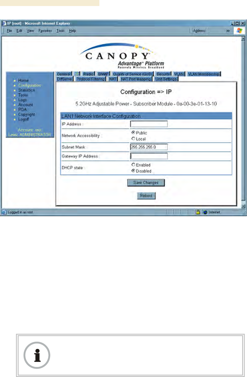
Figure 93: IP tab of SM with NAT disabled, example
This implementation is illustrated in Figure 46 on Page 157. In the IP tab of an SM with
NAT disabled, you may set the following parameters.
LAN1 Network Interface Configuration, IP Address
Enter the non-routable IP address to associate with the Ethernet connection on this SM.
(The default IP address from the factory is 169.254.1.1.) If you set and then forget this
parameter, then you must both
1. physically access the module.
2. use an override plug to electronically access the module configuration
parameters at 169.254.1.1. See Overriding Forgotten IP Addresses or
Passwords on AP, SM, or BH on Page 377.
RECOMMENDATION:
Note or print the IP settings from this page. Ensure that you can readily
associate these IP settings both with the module and with the other data that you
store about the module.

Release 8 Installation and Configuration Guide
Issue 2, December 2006 Draft 2 for Regulatory Review 267
LAN1 Network Interface Configuration, Network Accessibility
Specify whether the IP address of the SM should be visible to only a device connected to
the SM by Ethernet (Local) or should be visible to the AP as well (Public).
LAN1 Network Interface Configuration, Subnet Mask
Enter an appropriate subnet mask for the SM to communicate on the network. The
default subnet mask is 255.255.0.0. See Allocating Subnets on Page 162.
LAN1 Network Interface Configuration, Gateway IP Address
Enter the appropriate gateway for the SM to communicate with the network. The default
gateway is 169.254.0.0.
LAN1 Network Interface Configuration, DHCP State
If you select Enabled, the DHCP server automatically assigns the IP configuration
(IP address, subnet mask, and gateway IP address) and the values of those individual
parameters (above) are not used. The setting of this DHCP state parameter is also
viewable, but not settable, in the Network Interface tab of the Home page.
In this tab, DHCP State is settable only if the Network Accessibility parameter in the IP
tab is set to Public. This parameter is also settable in the NAT tab of the Configuration
web page, but only when NAT is enabled.
The IP tab also contains the following buttons.
Save Changes
When you click this button, any changes that you made on all tabs are recorded in flash
memory. However, these changes do not apply until the next reboot of the module.
Reboot
When you click this button
1. the module reboots.
2. any changes that you saved by a click of the Save Changes button are
implemented.
Installation and Configuration Guide Release 8
268 Draft 2 for Regulatory Review Issue 2, December 2006
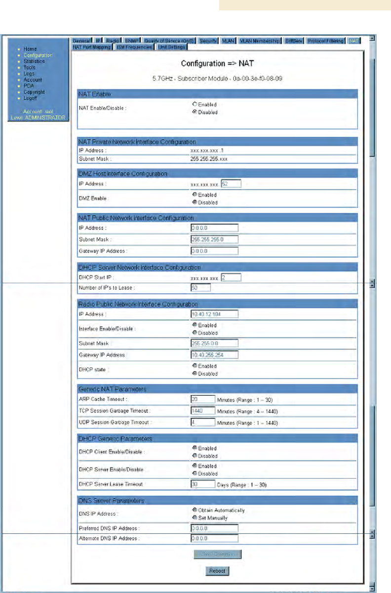
18.2.3 NAT and IP Tabs of the SM with NAT Enabled
An example of the NAT tab in an SM with NAT enabled is displayed in Figure 94.
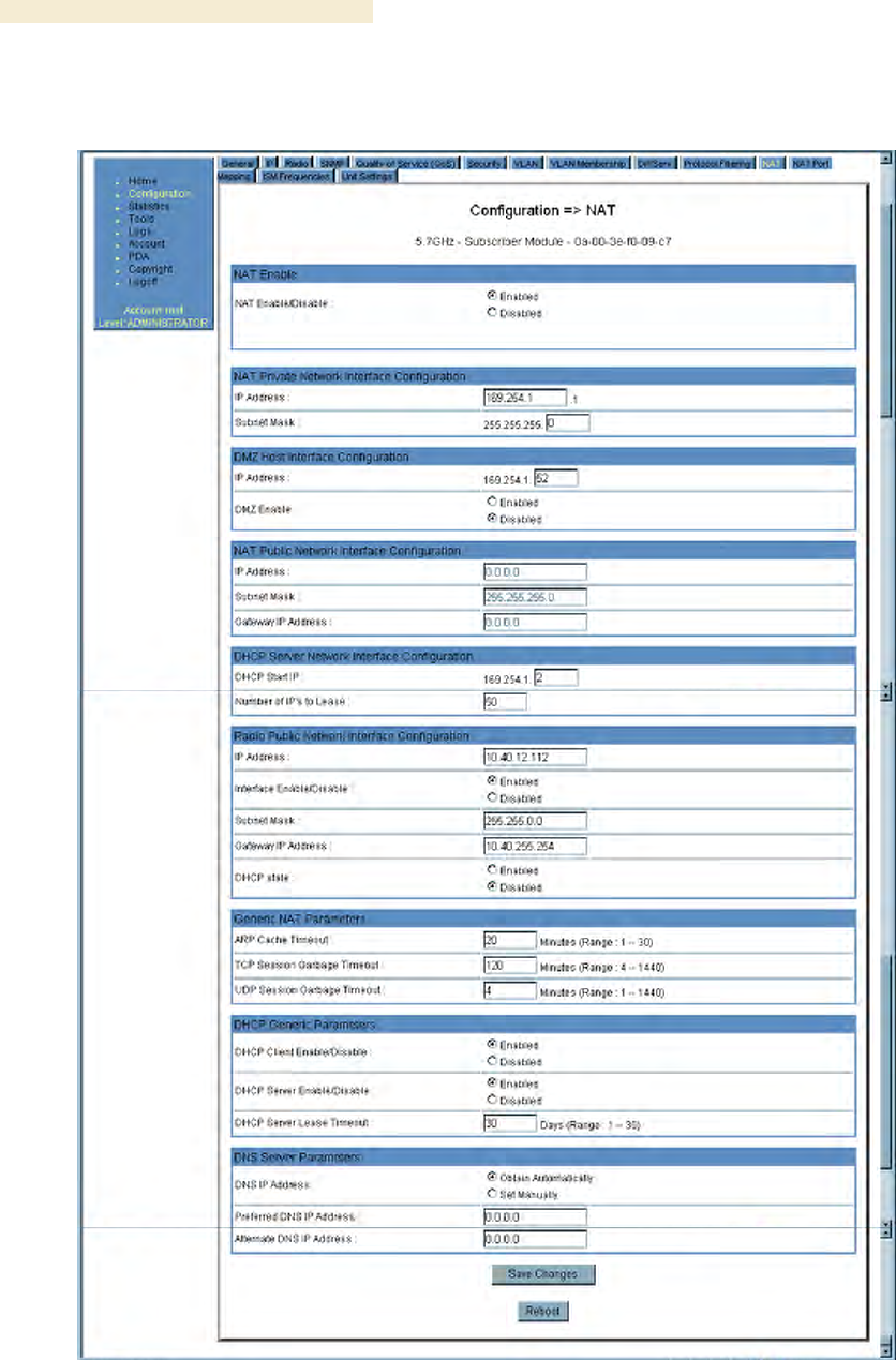
Figure 94: NAT tab of SM with NAT enabled, example
In the NAT tab of an SM with NAT enabled, you may set the following parameters.

Release 8 Installation and Configuration Guide
Issue 2, December 2006 Draft 2 for Regulatory Review 269
NAT Enable/Disable
This parameter enables or disabled the Network Address Translation (NAT) feature for
the SM. NAT isolates devices connected to the Ethernet/wired side of an SM from being
seen directly from the wireless side of the SM. With NAT enabled, the SM has an IP
address for transport traffic separate from its address for management, terminates
transport traffic, and allows you to assign a range of IP addresses to devices that are
connected to the Ethernet/wired side of the SM. For further information, see Network
Address Translation (NAT) on Page 156 and NAT and IP Tabs of the SM with NAT
Enabled on Page 268.
NAT Private Network Interface Configuration, IP Address
Assign an IP address for SM management through Ethernet access to the SM. Set only
the first three bytes. The last byte is permanently set to 1. This address becomes the
base for the range of DHCP-assigned addresses.
NAT Private Network Interface Configuration, Subnet Mask
Assign a subnet mask of 255.255.255.0 or a more restrictive subnet mask. Set only the
last byte of this subnet mask. Each of the first three bytes is permanently set to 255.
DMZ Host Interface Configuration, IP Address
If you will be enabling DMZ in the next parameter, set the last byte of the DMZ host IP
address to use for this SM when DMZ is enabled. Only one such address is allowed.
The first three bytes are identical to those of the NAT private IP address. Ensure that the
device that should receive network traffic behind this SM is assigned this address.
The system provides a warning if you enter an address within the range that DHCP can
assign.
DMZ Enable
Either enable or disable DMZ for this SM. See DMZ on Page 156.
NAT Public Network Interface Configuration, IP Address
This field displays the IP address of the SM. If DHCP Client is enabled, then the DHCP
server automatically assigns this address.
NAT Public Network Interface Configuration, Subnet Mask
This field displays the subnet mask of the SM. If DHCP Client is enabled, then the DHCP
server automatically assigns this subnet mask.
NAT Public Network Interface Configuration, Gateway IP Address
This field displays the gateway IP address for the SM. If DHCP Client is enabled, then the
DHCP server automatically assigns this gateway IP address.
DHCP Start IP
If you will be enabling DHCP Server below, set the last byte of the starting IP address
that the DHCP server will assign. The first three bytes are identical to those of the NAT
private IP address.
Number of IPs to Lease
Enter how many IP addresses the DHCP server is allowed to assign. The default value is
50 addresses.
Installation and Configuration Guide Release 8
270 Draft 2 for Regulatory Review Issue 2, December 2006
Radio Public Network Interface Configuration, IP Address
If DHCP Client is enabled, then the DHCP server automatically assigns this address.
Otherwise, assign the IP address for over-the-air management of the SM when the radio
public interface is enabled in the next parameter.
Radio Public Network Interface Configuration, Interface Enable/Disable
If you want over-the-air management capability for the SM, select Enabled. If you want to
limit management of the SM to its Ethernet interface, select Disabled.
Radio Public Network Interface Configuration, Subnet Mask
If DHCP Client is enabled, then the DHCP server automatically assigns this subnet mask.
Otherwise, assign the subnet mask for over-the-air management of the SM when the
radio public interface is enabled.
Radio Public Network Interface Configuration, Gateway IP Address
If DHCP Client is enabled, then the DHCP server automatically assigns this gateway IP
address. Otherwise, assign the gateway IP address for over-the-air management of the
SM when the radio public network interface is enabled.
RECOMMENDATION:
Note or print the IP settings from this page. Ensure that you can readily
associate these IP settings both with the module and with the other data that you
store about the module.
Radio Public Network Interface Configuration, DHCP State
If you select Enabled, the DHCP server automatically assigns the IP configuration
(IP address, subnet mask, and gateway IP address) and the values of those individual
parameters (above) are not used. The setting of this DHCP state parameter is also
viewable, but not settable, in the Network Interface tab of the Home page.
ARP Cache Timeout
If a router upstream has an ARP cache of longer duration (as some use 30 minutes),
enter a value of longer duration than the router ARP cache. The default value of this field
is 20 minutes.
TCP Session Garbage Timeout
Where a large network exists behind the SM, you can set this parameter to lower than
the default value of 1440 minutes (24 hours). This action makes additional resources
available for greater traffic than the default value accommodates. The default value of
this parameter is 120 minutes.
UDP Session Garbage Timeout
You may adjust this parameter in the range of 1 to 1440 minutes, based on network
performance. The default value of this parameter is 4 minutes.

Release 8 Installation and Configuration Guide
Issue 2, December 2006 Draft 2 for Regulatory Review 271
DHCP Client Enable/Disable
Select either
◦ Enabled to allow the network DHCP server to assign IP addresses, subnet
masks, and gateway IP addresses to devices that are attached to the SM.
◦ Disabled to
− disable DHCP server assignment of this address.
− enable the operator to assign this address.
The implementation of NAT with DHCP client is illustrated in Figure 48 on Page 159.
The implementation of NAT with DHCP client and DHCP server is illustrated in Figure 47
on Page 158. The implementation of NAT without DHCP is illustrated in Figure 50 on
Page 161.
DHCP Server Enable/Disable
Select either
◦ Enabled to
− allow this SM to assign IP addresses, subnet masks, and gateway IP
addresses to attached devices.
− assign a start address for DHCP.
− designate how many IP addresses may be temporarily used (leased).
◦ Disabled to disallow the SM to assign addresses to attached devices.
The implementation of NAT with DHCP server is illustrated in Figure 49 on Page 50.
The implementation of NAT with DHCP client and DHCP server is illustrated in Figure 47
on Page 158. The implementation of NAT without DHCP is illustrated in Figure 50 on
Page 161.
DHCP Server Lease Timeout
Based on network performance, enter the number of days between when the DHCP
server assigns an IP address and when that address expires. The range of values for this
parameter is 1 to 30 days. The default value is 30 days.
DNS IP Address
Select either
◦ Obtain Automatically to allow the system to set the IP address of the DNS
server.
◦ Set Manually to enable yourself to set both a preferred and an alternate DNS IP
address.
Preferred DNS IP Address
Enter the preferred DNS IP address to use when the DNS IP Address parameter is set
to Set Manually.
Alternate DNS IP Address
Enter the DNS IP address to use when the DNS IP Address parameter is set to Set
Manually and no response is received from the preferred DNS IP address.
The NAT tab also contains the following buttons.
Installation and Configuration Guide Release 8
272 Draft 2 for Regulatory Review Issue 2, December 2006
Save Changes
When you click this button, any changes that you made on all tabs are recorded in flash
memory. However, these changes do not apply until the next reboot of the module.
Reboot
When you click this button
1. the module reboots.
2. any changes that you saved by a click of the Save Changes button are
implemented.
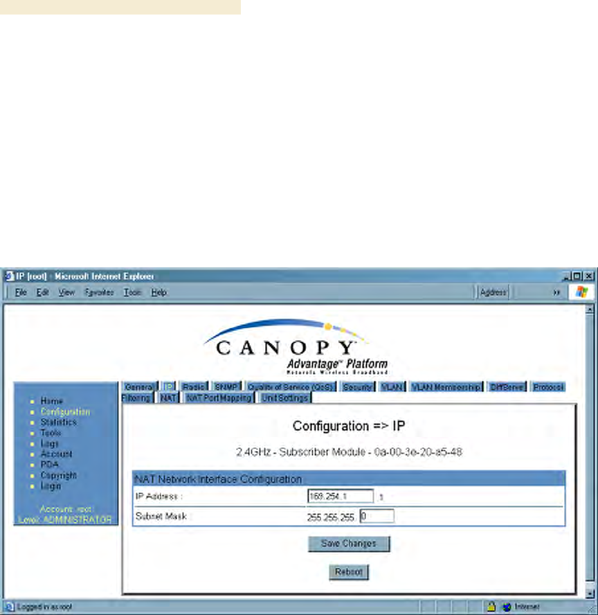
An example of the IP tab in an SM with NAT enabled is displayed in Figure 95.
Figure 95: IP tab of SM with NAT enabled, example
In the IP tab of an SM with NAT enabled, you may set the following parameters.
NAT Network Interface Configuration, IP Address
Assign an IP address for SM management through Ethernet access to the SM. Set only
the first three bytes. The last byte is permanently set to 1. This address becomes the
base for the range of DHCP-assigned addresses.
NAT Network Interface Configuration, Subnet Mask
Assign a subnet mask of 255.255.255.0 or a more restrictive subnet mask. Set only the
last byte of this subnet mask. Each of the first three bytes is permanently set to 255.
The IP tab also contains the following buttons.
Save Changes
When you click this button, any changes that you made on all tabs are recorded in flash
memory. However, these changes do not apply until the next reboot of the module.
Release 8 Installation and Configuration Guide
Issue 2, December 2006 Draft 2 for Regulatory Review 273
Reboot
When you click this button
1. the module reboots.
2. any changes that you saved by a click of the Save Changes button are
implemented.
An example of the IP tab in an SM with NAT enabled is displayed in Figure 95.
18.2.4 Radio Tab of the SM
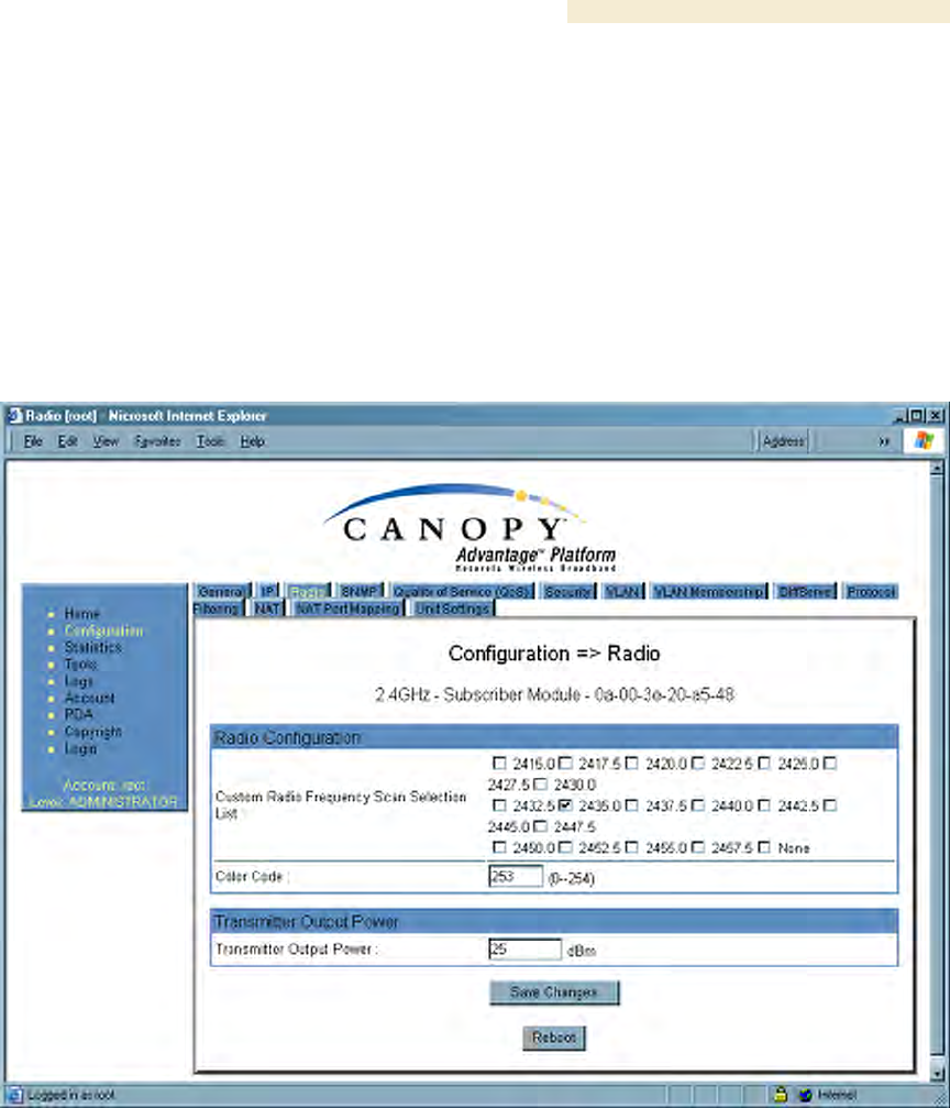
An example of the Radio tab in the SM is displayed in Figure 96.
Figure 96: Radio tab of SM, example
In the Radio tab of the SM, you may set the following parameters.
Custom Radio Frequency Scan Selection List
Check any frequency that you want the SM to scan for AP transmissions. The frequency
band of the SM affects what channels you should select.
Installation and Configuration Guide Release 8
274 Draft 2 for Regulatory Review Issue 2, December 2006
IMPORTANT!
In the 2.4-GHz frequency band, the SM can register to an AP that transmits on a
frequency 2.5 MHz higher than the frequency that the SM receiver locks when
the scan terminates as successful. This establishes a poor-quality link. To
prevent this, select frequencies that are at least 5 MHz apart.
In a 2.4-GHz SM, this parameter displays all available channels, but has only three
recommended channels selected by default. See 2.4-GHz AP Cluster Recommended
Channels on Page 137.
In a 5.2- or 5.4-GHz SM, this parameter displays only ISM frequencies. In a 5.7-GHz SM,
this parameter displays both ISM and U-NII frequencies. If you select all frequencies that
are listed in this field (default selections), then the SM scans for a signal on any channel.
If you select only one, then the SM limits the scan to that channel. Since the frequencies
that this parameter offers for each of these two bands are 5 MHz apart, a scan of all
channels does not risk establishment of a poor-quality link as in the 2.4-GHz band.
A list of channels in the band is provided in Considering Frequency Band Alternatives on
Page 136.
(The selection labeled Factory requires a special software key file for implementation.)
Color Code
Color code allows you to force the SM to register to only a specific AP, even where the
SM can communicate with multiple APs. For registration to occur, the color code of the
SM and the AP must match. Specify a value from 0 to 254.
Color code is not a security feature. Instead, color code is a management feature,
typically for assigning each sector a different color code. On all Canopy modules,
the default setting for the color code value is 0. This value matches only the color code
of 0 (not all 255 color codes).
RECOMMENDATION:
Note the color code that you enter. Ensure that you can readily associate this
color code both with the module and with the other data that you store about the
module.
External Filters Delay
This parameter is present in only 900-MHz modules and can have effect in only those
that have interference mitigation filter(s). If this value is present, leave it set to 0,
regardless of whether the SM has an interference mitigation filter.

Release 8 Installation and Configuration Guide
Issue 2, December 2006 Draft 2 for Regulatory Review 275
Transmitter Output Power
Nations and regions may regulate transmitter output power. For example
◦ Both 900-MHz and 5.7-GHz modules are available as connectorized radios,
which require the operator to adjust power to ensure regulatory compliance. In
addition to setting the power in the 5.7-GHz connectorized module, the operator
must set the antenna gain/cable loss such that the module can accurately report
received power at the antenna.
◦ Legal maximum allowable transmitter output power and EIRP (Equivalent
Isotropic Radiated Power) in the 2.4-GHz frequency band varies by country and
region. The output power of Series P9 2.4-GHz modules can be adjusted to meet
these national or regional regulatory requirements.
◦ Countries and regions that permit the use of the 5.4-GHz frequency band (CEPT
member states, for example), generally require equipment using the band to
have adjustable power.
The professional installer of Canopy equipment has the responsibility to
◦ maintain awareness of applicable regulations.
◦ calculate the permissible transmitter output power for the module.
◦ confirm that the initial power setting is compliant with national or regional
regulations.
◦ confirm that the power setting is compliant following any reset of the module to
factory defaults.
For information on how to calculate the permissible transmitter output power to enter in
this parameter, see Adjusting Transmitter Output Power on Page 326.
The Radio tab also contains the following buttons.
Save Changes
When you click this button, any changes that you made on all tabs are recorded in flash
memory. However, these changes do not apply until the next reboot of the module.
Reboot
When you click this button
1. the module reboots.
2. any changes that you saved by a click of the Save Changes button are
implemented.
Installation and Configuration Guide Release 8
276 Draft 2 for Regulatory Review Issue 2, December 2006
18.2.5 SNMP Tab of the SM
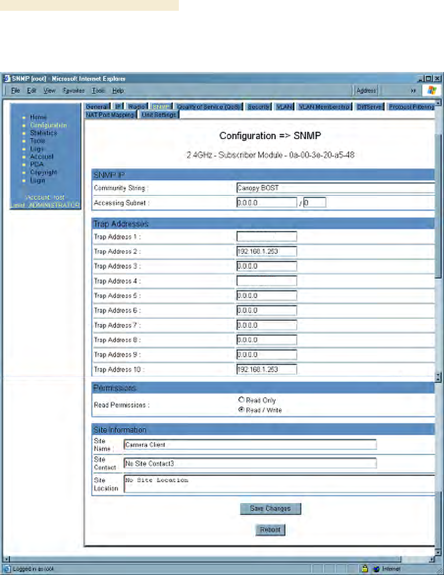
An example of the SNMP tab in an SM is displayed in Figure 97.
Figure 97: SNMP tab of SM, example
In the SNMP tab of the SM, you may set the following parameters.
Community String
Specify a control string that allows Prizm or an NMS (Network Management Station) to
access MIB information about this SM. No spaces are allowed in this string. The default
string is Canopy.
Release 8 Installation and Configuration Guide
Issue 2, December 2006 Draft 2 for Regulatory Review 277
The Community String value is clear text and is readable by a packet monitor.
Additional security derives from the configuration of the Accessing Subnet, Trap
Address, and Permission parameters.
Accessing Subnet
Specify the addresses that are allowed to send SNMP requests to this SM. Prizm or
the NMS has an address that is among these addresses (this subnet). You must enter
both
◦ The network IP address in the form xxx.xxx.xxx.xxx
◦ The CIDR (Classless Interdomain Routing) prefix length in the form /xx
For example
◦ the /16 in 198.32.0.0/16 specifies a subnet mask of 255.255.0.0 (the first 16 bits
in the address range are identical among all members of the subnet).
◦ 192.168.102.0 specifies that any device whose IP address is in the range
192.168.102.0 to 192.168.102.254 can send SNMP requests to the SM,
presuming that the device supplies the correct Community String value.
The default treatment is to allow all networks access (set to 0). For more information on
CIDR, execute an Internet search on “Classless Interdomain Routing.”
RECOMMENDATION:
The subscriber can access the SM by changing the subscriber device to the
accessing subnet. This hazard exists because the Community String and
Accessing Subnet are both visible parameters. To avoid this hazard, configure
the SM to filter (block) SNMP requests. See Filtering Protocols and Ports on
Page 378.
Trap Address 1 to 10
Specify ten or fewer IP addresses (xxx.xxx.xxx.xxx) to which trap information should be
sent. Trap information informs Prizm or an NMS that something has occurred. For
example, trap information is sent
◦ after a reboot of the module.
◦ when Prizm or an NMS attempts to access agent information but either
− supplied an inappropriate community string or SNMP version number.
− is associated with a subnet to which access is disallowed.
Read Permissions
Select Read Only if you wish to disallow Prizm or NMS SNMP access to configurable
parameters and read-only fields of the SM.
Site Name
Specify a string to associate with the physical module. This parameter is written into the
sysName SNMP MIB-II object and can be polled by Prizm or an NMS. The buffer size for
this field is 128 characters.

Installation and Configuration Guide Release 8
278 Draft 2 for Regulatory Review Issue 2, December 2006
Site Contact
Enter contact information for the module administrator. This parameter is written into the
sysContact SNMP MIB-II object and can be polled by Prizm or an NMS. The buffer size
for this field is 128 characters.
Site Location
Enter information about the physical location of the module. This parameter is written into
the sysLocation SNMP MIB-II object and can be polled by Prizm or an NMS. The buffer
size for this field is 128 characters.
The SNMP tab also provides the following buttons.
Save Changes
When you click this button, any changes that you made on the Configuration page are
recorded in flash memory. However, these changes do not apply until the next reboot of
the module.
Reboot
When you click this button
1. the module reboots.
2. any changes that you saved by a click of the Save Changes button are
implemented.
Release 8 Installation and Configuration Guide
Issue 2, December 2006 Draft 2 for Regulatory Review 279
18.2.6 Quality of Service (QoS) Tab of the SM
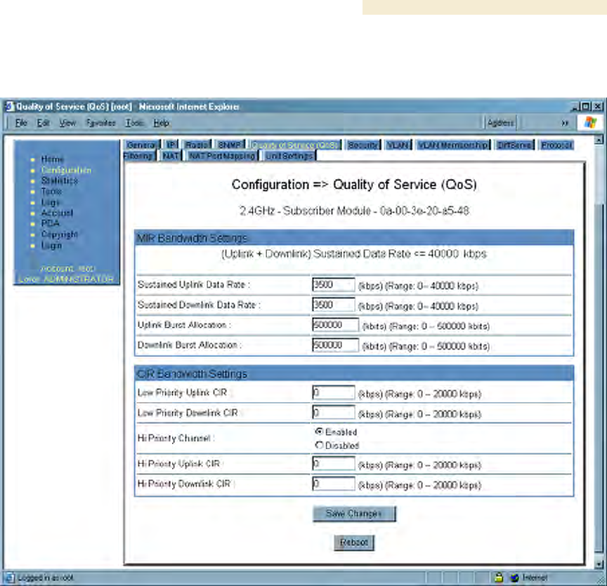
An example of the Quality of Service (QoS) tab in the SM is displayed in Figure 98.
Figure 98: Quality of Service (QoS) tab of SM, example
In the Quality of Service (QoS) tab of the SM, you may set the following parameters.
Sustained Uplink Data Rate
Specify the rate that this SM is replenished with credits for transmission. This default
imposes no restriction on the uplink. See
◦ Maximum Information Rate (MIR) Parameters on Page 85
◦ Interaction of Burst Allocation and Sustained Data Rate Settings on Page 88
◦ Setting the Configuration Source on Page 292.
Sustained Downlink Data Rate
Specify the rate at which the AP should be replenished with credits (tokens) for
transmission to this SM. This default imposes no restriction on the uplink. See
◦ Maximum Information Rate (MIR) Parameters on Page 85
◦ Interaction of Burst Allocation and Sustained Data Rate Settings on Page 88
◦ Setting the Configuration Source on Page 292.

Installation and Configuration Guide Release 8
280 Draft 2 for Regulatory Review Issue 2, December 2006
Uplink Burst Allocation
Specify the maximum amount of data to allow this SM to transmit before being recharged
at the Sustained Uplink Data Rate with credits to transmit more. See
◦ Maximum Information Rate (MIR) Parameters on Page 85
◦ Interaction of Burst Allocation and Sustained Data Rate Settings on Page 88
◦ Setting the Configuration Source on Page 292.
Downlink Burst Allocation
Specify the maximum amount of data to allow the AP to transmit to this SM before the AP
is replenished at the Sustained Downlink Data Rate with transmission credits. See
◦ Maximum Information Rate (MIR) Parameters on Page 85
◦ Interaction of Burst Allocation and Sustained Data Rate Settings on Page 88
◦ Setting the Configuration Source on Page 292.
Low Priority Uplink CIR
See
◦ Committed Information Rate on Page 87
◦ Setting the Configuration Source on Page 292.
Low Priority Downlink CIR
See
◦ Committed Information Rate on Page 87
◦ Setting the Configuration Source on Page 292.
Hi Priority Channel
See
◦ High-priority Bandwidth on Page 88
◦ Setting the Configuration Source on Page 292.
Hi Priority Uplink CIR
See
◦ High-priority Bandwidth on Page 88
◦ Committed Information Rate on Page 87
◦ Setting the Configuration Source on Page 292.
Hi Priority Downlink CIR
See
◦ High-priority Bandwidth on Page 88

Release 8 Installation and Configuration Guide
Issue 2, December 2006 Draft 2 for Regulatory Review 281
◦ Committed Information Rate on Page 87
◦ Setting the Configuration Source on Page 292.
The Quality of Service (QoS) tab also provides the following buttons.
Save Changes
When you click this button, any changes that you made in this tab are recorded in flash
memory. However, these changes do not apply until the next reboot of the module.
Reboot
When you click this button
1. the module reboots.
2. any changes that you saved by a click of the Save Changes button are
implemented.
Installation and Configuration Guide Release 8
282 Draft 2 for Regulatory Review Issue 2, December 2006
18.2.7 Security Tab of the SM
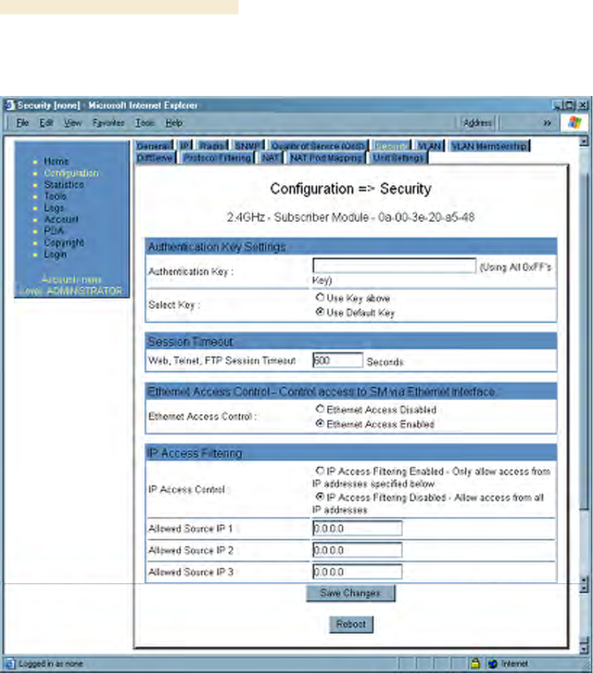
An example of the Security tab in an SM is displayed in Figure 99.
Figure 99: Security tab of SM, example
Release 8 Installation and Configuration Guide
Issue 2, December 2006 Draft 2 for Regulatory Review 283
In the Security tab of the SM, you may set the following parameters.
Authentication Key
Only if the AP to which this SM will register requires authentication, specify the key that
the SM should use when authenticating. For alpha characters in this hex key, use only
upper case.
Select Key
The Use Default Key selection specifies the predetermined key for authentication in
BAM or Prizm. See Authentication Manager Capability on Page 385.
The Use Key above selection specifies the 32-digit hexadecimal key that is permanently
stored on both the SM and the BAM or Prizm database.
NOTE:
The SM and BAM or Prizm pad the key of any length by the addition of leading
zeroes, and if the entered keys match, authentication attempts succeed.
However, Canopy recommends that you enter 32 characters to achieve the
maximal security from this feature.
Web, Telnet, FTP Session Timeout
Enter the expiry in seconds for remote management sessions via HTTP, telnet, or ftp
access to the SM.
Ethernet Access Control
If you want to prevent any device that is connected to the Ethernet port of the SM from
accessing the management interface of the SM, select Ethernet Access Disabled. This
selection disables access through this port to via http (the GUI), SNMP, telnet, ftp, and
tftp. With this selection, management access is available through only the RF interface
via either an IP address (if Network Accessibility is set to Public on the SM) or the
Session Status or Remote Subscribers tab of the AP.
NOTE:
This setting does not prevent a device connected to the Ethernet port from
accessing the management interface of other SMs in the network. To prevent
this, use the IP Access Filtering Enabled selection in the IP Access Control
parameter of the SMs in the network. See IP Access Control below.
If you want to allow management access through the Ethernet port, select
Ethernet Access Enabled. This is the factory default setting for this parameter.
IP Access Control
You can permit access to the SM from any IP address (IP Access Filtering Disabled) or
limit it to access from only one, two, or three IP addresses that you specify (IP Access
Filtering Enabled). If you select IP Access Filtering Enabled, then you must populate
at least one of the three Allowed Source IP parameters or have no access permitted
from any IP address, including access and management by Prizm.
Installation and Configuration Guide Release 8
284 Draft 2 for Regulatory Review Issue 2, December 2006
Allowed Source IP 1 to 3
If you selected IP Access Filtering Enabled for the IP Access Control parameter, then
you must populate at least one of the three Allowed Source IP parameters or have no
access permitted to the SM from any IP address. You may populate as many as all three.
If you selected IP Access Filtering Disabled for the IP Access Control parameter, then
no entries in this parameter are read, and access from all IP addresses is permitted.
The Security tab of the SM also provides the following buttons.
Save Changes
When you click this button, any changes that you made on this tab are recorded in flash
memory. However, these changes do not apply until the next reboot of the module.
Reboot
When you click this button
1. the module reboots.
2. any changes that you saved by a click of the Save Changes button are
implemented.
18.2.8 VLAN Tab of the SM
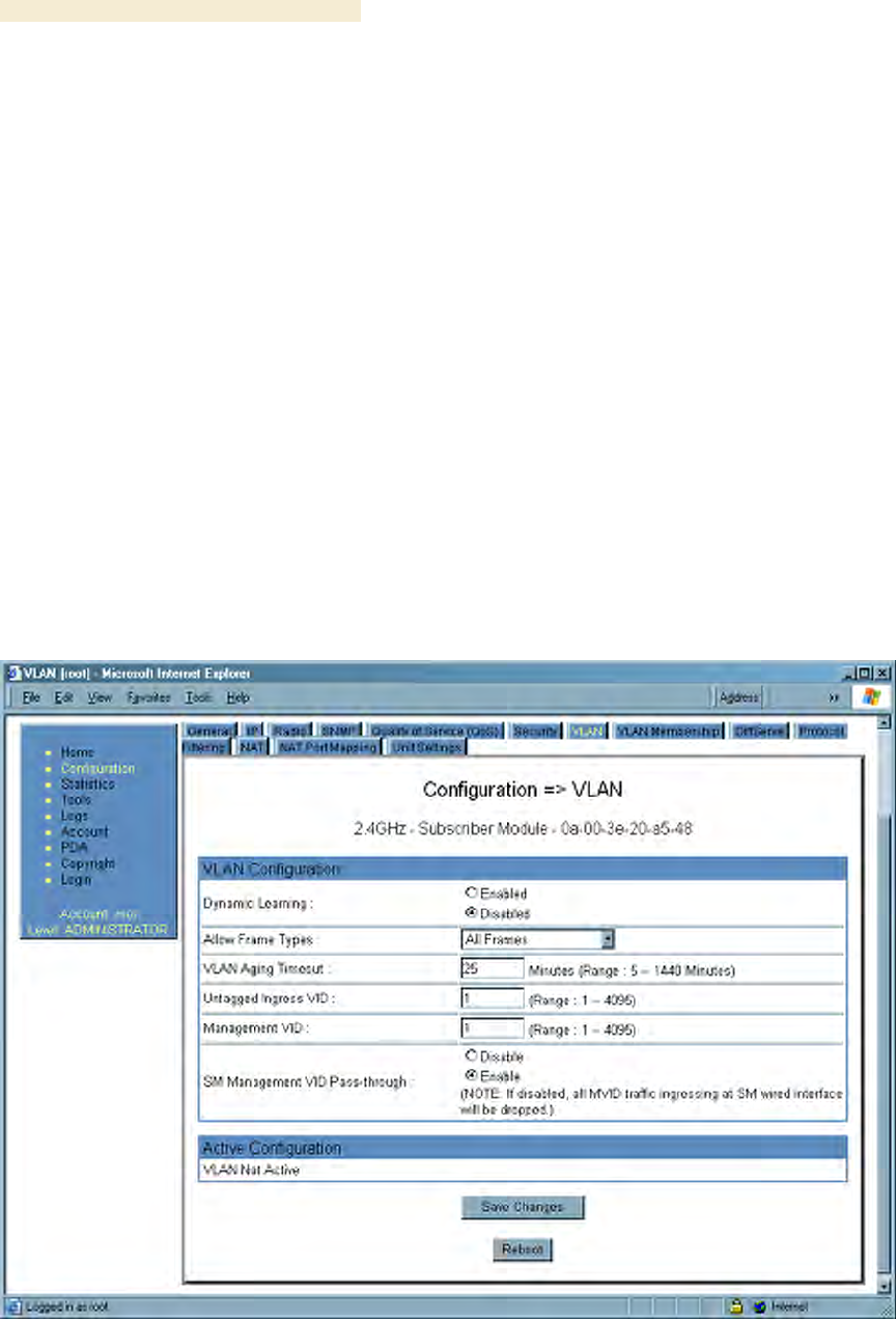
An example of the VLAN tab in an SM is displayed in Figure 100.
Figure 100: VLAN tab of SM, example
Release 8 Installation and Configuration Guide
Issue 2, December 2006 Draft 2 for Regulatory Review 285
In the VLAN tab of an SM, you may set the following parameters.
Dynamic Learning
Specify whether the SM should (Enable) or should not (Disable) add the VIDs of
upstream frames (that enter the SM through the wired Ethernet interface) to the VID
table. The default value is Enable.
Allow Frame Types
Select the type of arriving frames that the SM should tag, using the VID that is stored in
the Untagged Ingress VID parameter. The default value is All Frames.
VLAN Aging Timeout
Specify how long the SM should keep dynamically learned VIDs. The range of values is 5
to 1440 (minutes). The default value is 25 (minutes).
NOTE:
VIDs that you enter for the Untagged Ingress VID and Management VID
parameters do not time out.
Untagged Ingress VID
Enter the VID that the SM(s) should use to tag frames that arrive at the SM(s) untagged.
The range of values is 1 to 4095. The default value is 1.
Management VID
Enter the VID that the SM should share with the AP. The range of values is 1 to 4095.
The default value is 1.
SM Management VID Pass-through
Specify whether to allow the SM (Enable) or the AP (Disable) to control the VLAN
settings of this SM. The default value is Enable.
The VLAN tab also provides the following buttons.
Save Changes
When you click this button, any changes that you made on this tab are recorded in flash
memory. However, these changes do not apply until the next reboot of the module.
Reboot
When you click this button
1. the module reboots.
2. any changes that you saved by a click of the Save Changes button are
implemented.
Installation and Configuration Guide Release 8
286 Draft 2 for Regulatory Review Issue 2, December 2006
18.2.9 VLAN Membership Tab of the SM
An example of the VLAN Membership tab in an SM is displayed in Figure 101.
Figure 101: VLAN Membership tab of SM, example
In the VLAN Membership tab, you may set the following parameter.
VLAN Membership Table Configuration
For each VLAN in which you want the AP to be a member, enter the VLAN ID and then
click the Add Member button. Similarly, for any VLAN in which you want the AP to no
longer be a member, enter the VLAN ID and then click the Remove Member button.
Release 8 Installation and Configuration Guide
Issue 2, December 2006 Draft 2 for Regulatory Review 287
18.2.10 DiffServe Tab of the SM
An example of the DiffServe tab in an SM is displayed in Figure 102.
Figure 102: DiffServe tab of SM, example

Installation and Configuration Guide Release 8
288 Draft 2 for Regulatory Review Issue 2, December 2006
In the DiffServe tab of the SM, you may set the following parameters.
CodePoint 1
through
CodePoint 47
CodePoint 49
through
CodePoint 55
CodePoint 57
through
CodePoint 63
The default priority value for each settable CodePoint is shown in
Figure 119. Priorities of 0 through 3 map to the low-priority channel;
4 through 7 to the high-priority channel. The mappings are the same
as 802.1p VLAN priorities.
Consistent with RFC 2474
◦ CodePoint 0 is predefined to a fixed priority value of 0
(low-priority channel).
◦ CodePoint 48 is predefined to a fixed priority value of 6
(high-priority channel).
◦ CodePoint 56 is predefined to a fixed priority value of 7
(high-priority channel).
You cannot change any of these three fixed priority values. Among
the settable parameters, the priority values (and therefore the
handling of packets in the high- or low-priority channel) are set in
the AP for all downlinks within the sector and in the SM for each
uplink. See DSCP Field on Page 89.
The DiffServe tab of the SM also provides the following buttons.
Save Changes
When you click this button, any changes that you made on this tab are recorded in flash
memory. However, these changes do not apply until the next reboot of the module.
Reboot
When you click this button
1. the module reboots.
2. any changes that you saved by a click of the Save Changes button are
implemented.
Release 8 Installation and Configuration Guide
Issue 2, December 2006 Draft 2 for Regulatory Review 289
18.2.11 Protocol Filtering Tab of the SM
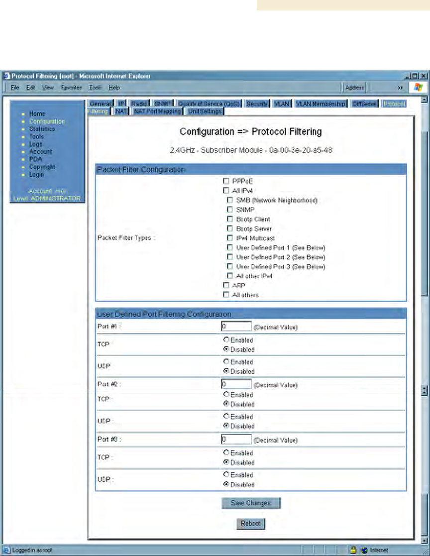
An example of the Protocol Filtering tab in an SM is displayed in Figure 103.
Figure 103: Protocol Filtering tab of SM, example
In the Protocol Filtering tab of the SM, you may set the following parameters.
Packet Filter Types
For any box selected, the Protocol and Port Filtering feature blocks the associated
protocol type. Examples are provided in Protocol and Port Filtering with NAT Disabled on
Page 378.
Installation and Configuration Guide Release 8
290 Draft 2 for Regulatory Review Issue 2, December 2006
To filter packets in any of the user-defined ports, you must do all of the following:
◦ Check the box for User Defined Port n (See Below) in the Packet Filter Types
section of this tab.
◦ In the User Defined Port Filtering Configuration section of this tab, both
− provide a port number at Port #n.
− check TCP, UDP, or both.
User Defined Port Filtering Configuration
You can specify ports for which to block subscriber access, regardless of whether NAT is
enabled. For more information, see Filtering Protocols and Ports on Page 378.
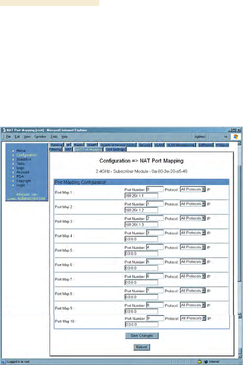
18.2.12 NAT Port Mapping Tab of the SM
An example of the NAT Port Mapping tab in an SM is displayed in Figure 104.
Figure 104: NAT Port Mapping tab of SM, example
Release 8 Installation and Configuration Guide
Issue 2, December 2006 Draft 2 for Regulatory Review 291
In the NAT Port Mapping tab of the SM, you may set the following parameters.
Port Map 1 to 10
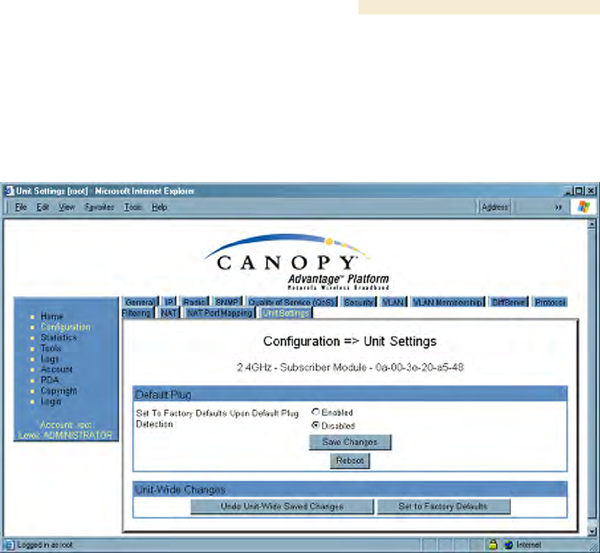
18.2.13 Unit Settings Tab of the SM
An example of the Unit Settings tab in an SM is displayed in Figure 105.
Figure 105: Unit Settings tab of SM, example
The Unit Settings tab of the SM contains an option for how the SM should react when it
detects a connected override plug. You may set this option as follows.
Set to Factory Defaults Upon Default Plug Detection
If Enabled is checked, then an override/default plug functions as a default plug. When
the module is rebooted with the plug inserted, it can be accessed at the IP address
169.254.1.1 and no password, and all parameter values are reset to defaults.
A subscriber, technician, or other person who gains physical access to the module and
uses an override/default plug cannot see or learn the settings that were previously
configured in it. When the module is later rebooted with no plug inserted, the module
uses the new values for any parameters that were changed and the default values for
any that were not.
If Disabled is checked, then an override/default plug functions as an override plug. When
the module is rebooted with the plug inserted, it can be accessed at the IP address
169.254.1.1 and no password, and all previously configured parameter values remain
and are displayed. A subscriber, technician, or other person who gains physical access
to the module and uses an override/default plug can see and learn the settings. When the
module is later rebooted with no plug inserted, the module uses the new values for any
parameters that were changed and the previous values for any that were not.

Installation and Configuration Guide Release 8
292 Draft 2 for Regulatory Review Issue 2, December 2006
See Overriding Forgotten IP Addresses or Passwords on AP, SM, or BH on Page 375.
The Unit Settings tab also contains the following buttons.
Save Changes
When you click this button, any changes that you made on all tabs are recorded in flash
memory. However, these changes do not apply until the next reboot of the module.
Undo Unit-Wide Saved Changes
When you click this button, any changes that you made in any tab but did not commit by
a reboot of the module are undone.
Set to Factory Defaults
When you click this button, all configurable parameters on all tabs are reset to the factory
settings.
Reboot
When you click this button
1. the module reboots.
2. any changes that you saved by a click of the Save Changes button are
implemented.
18.3 SETTING THE CONFIGURATION SOURCE
The AP includes a Configuration Source parameter, which sets where SMs that register
to the AP are controlled for MIR, VLAN, the high-priority channel, and CIR as follows.
The Configuration Source parameter affects the source of
◦ all MIR settings:
− Sustained Uplink Data Rate
− Uplink Burst Allocation
− Sustained Downlink Data Rate
− Downlink Burst Allocation
◦ all SM VLAN settings:
− Dynamic Learning
− Allow Only Tagged Frames
− VLAN Ageing Timeout
− Untagged Ingress VID
− Management VID
− VLAN Membership
◦ the Hi Priority Channel setting
◦ all CIR settings
−Low Priority Uplink CIR
−Low Priority Downlink CIR
−Hi Priority Uplink CIR
−Hi Priority Downlink CIR
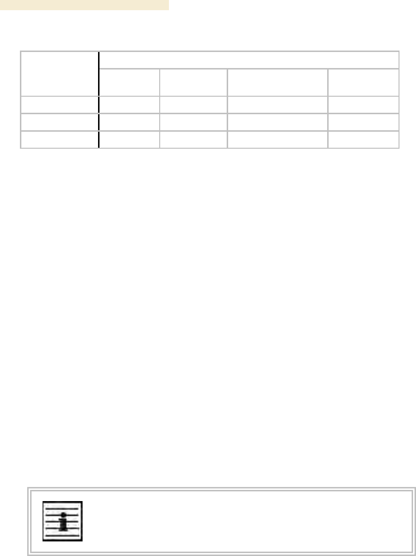
Most operators whose plans are typical should consult Table 49.

Release 8 Installation and Configuration Guide
Issue 2, December 2006 Draft 2 for Regulatory Review 293
Table 49: Recommended combined settings for typical operations
Most operators
who use…
should set this
parameter…
in this web
page…
of this
module…
to…
Authentication
Mode
Configuration>
Security
AP
Authentication
Disabled
none
Configuration
Source
Configuration>
General
AP
SM
Authentication
Mode
Configuration
AP
Authentication
Required
BAM Release 2.0
(Consider
upgrading to
Prizm)
Configuration
Source
Configuration
AP
BAM+SM
Authentication
Mode
Configuration
AP
Authentication
Required
BAM Release 2.1
(Consider
upgrading to
Prizm)
Configuration
Source
Configuration
AP
BAM
Authentication
Mode
Configuration
AP
Authentication
Required
Prizm Release 2.0
and 2.1
(being used for
BAM functionality)
Configuration
Source
Configuration
AP
BAM
Operators whose plans are atypical should consider the results that are described in
Table 50 and Table 51. For any SM whose Authentication Mode parameter is set to
Authentication Required, the listed settings are derived as shown in Table 50.
Table 50: Where feature values are obtained for an SM with authentication required
Values are obtained from
Configuration
Source Setting
in the AP
MIR Values
VLAN Values
High Priority Channel
State
CIR Values
BAM
BAM
BAM
BAM
BAM
SM
SM
SM
SM
SM
BAM+SM
BAM
BAM, then SM
BAM, then SM
BAM, then SM
NOTES:
HPC represents the Hi Priority Channel (enable or disable).
Where BAM, then SM is the indication, parameters for which BAM does not send values
are obtained from the SM. This is the case where the BAM server is operating on a BAM
release that did not support the feature. This is also the case where the feature enable/disable
flag in BAM is set to disabled. The values are those previously set or, if none ever were, then
the default values.
Where BAM is the indication, values in the SM are disregarded.
Where SM is the indication, values that BAM sends for the SM are disregarded.
The high-priority channel is unavailable to Series P7 and P8 SMs that run Canopy Release 8.
For any SM whose Authentication Mode parameter is not set to Authentication
Required, the listed settings are derived as shown in Table 51.
Installation and Configuration Guide Release 8
294 Draft 2 for Regulatory Review Issue 2, December 2006
Table 51: Where feature values are obtained for an SM with authentication disabled
Values are obtained from
Configuration
Source Setting
in the AP
MIR Values
VLAN Values
High Priority Channel
State
CIR Values
BAM
AP
AP
AP
AP
SM
SM
SM
SM
SM
BAM+SM
SM
SM
SM
SM
BAM Release 2.0 sends only MIR values. BAM Release 2.1 and Prizm Release 2.0
and 2.1 send VLAN and high-priority channel values as well.
For the case where the Configuration Source parameter in the AP is set to BAM, the
SM stores a value for the Dynamic Learning VLAN parameter that differs from its factory
default. When Prizm does not send VLAN values (because VLAN Enable is set to No in
Prizm), the SM
◦ uses this stored Disable value for Dynamic Learning.
◦ shows the following in the VLAN Configuration web page:
− either Enable or Disable as the value of the Dynamic Learning parameter.
− Allow Learning : No under Active Configuration.
For the case where the Configuration Source parameter in the AP is set to BAM+SM,
and Prizm does not send VLAN values, the SM
◦ uses the configured value in the SM for Dynamic Learning. If the SM is set to
factory defaults, then this value is Enable.
◦ shows under Active Configuration the result of the configured value in the SM.
For example, if the SM is set to factory defaults, then the VLAN Configuration
page shows Allow Learning : Yes.
This selection (BAM+SM) is not recommended where Prizm manages the VLAN feature
in SMs.
18.4 CONFIGURING A BH TIMING MASTER FOR THE DESTINATION
NOTE:
The OFDM Series BHs are described in their own dedicated user guides. See
Products Not Covered by This User Guide on Page 34.
If an ADMINISTRATOR-level password has been set in the BHM, you must log into the
module before you can configure its parameters. See Managing Module Access by
Passwords on Page 373.
Release 8 Installation and Configuration Guide
Issue 2, December 2006 Draft 2 for Regulatory Review 295
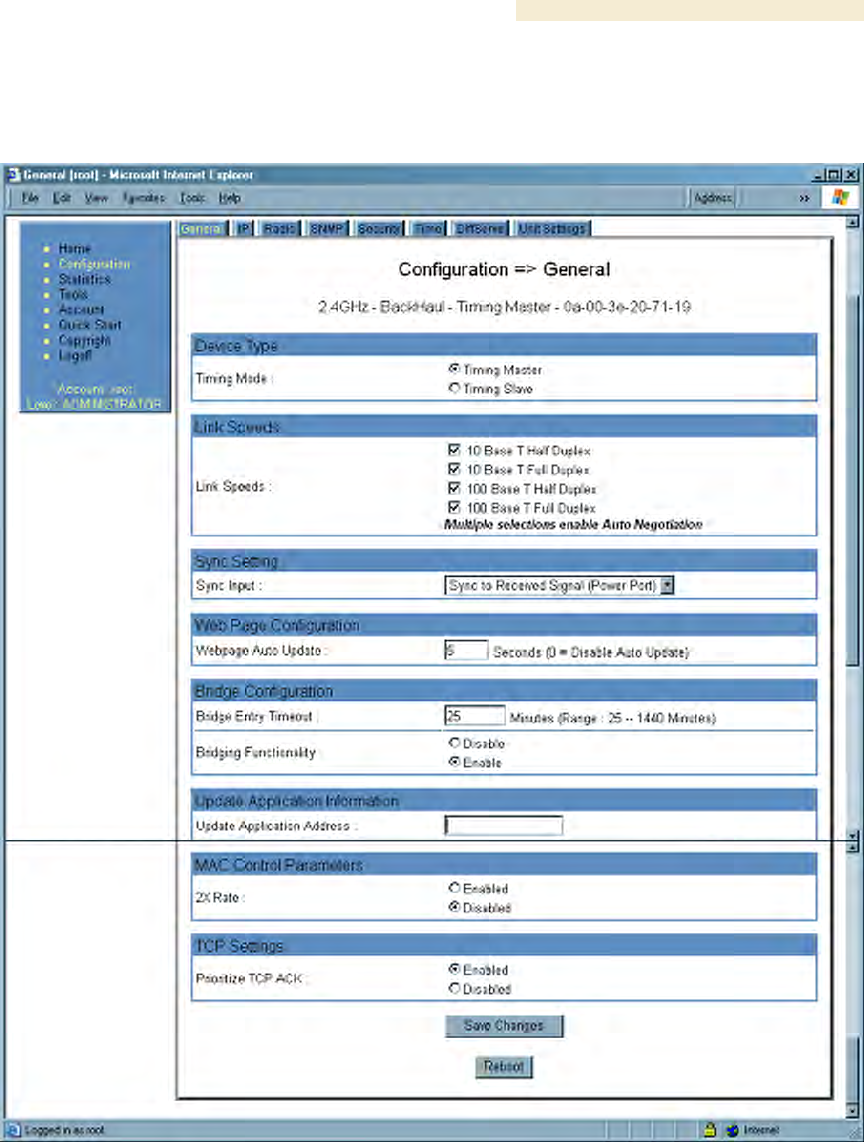
18.4.1 General Tab of the BHM
An example of the General tab in a BHM is displayed in Figure 106.
Figure 106: General tab of BHM, example

Installation and Configuration Guide Release 8
296 Draft 2 for Regulatory Review Issue 2, December 2006
In the General tab of the BHM, you may set the following parameters.
Timing Mode
Select Timing Master. This BH will provide sync for the link. Whenever you toggle this
parameter to Timing Master from Timing Slave, you should also do the following:
1. Make no other changes in this or any other interface page.
2. Save this change of timing mode.
3. Reboot the BH.
RESULT: The set of interface web pages that is unique to a BHM is made available.
Link Speeds
Specify the type of link speed for the Ethernet connection. The default for this parameter
is that all speeds are selected. The recommended setting is a single speed selection for
all APs, BHs, and SMs in the operator network.
Sync Input
Specify the type of synchronization for this BH timing master to use.
◦ Select Sync to Received Signal (Power Port) to set this BHM to receive sync
from a connected CMMmicro.
◦ Select Sync to Received Signal (Timing Port) to set this BHM to receive sync
from a connected CMM2, an AP in the cluster, an SM, or a BH timing slave.
◦ Select Generate Sync Signal where the BHM does not receive sync, and no AP
or other BHM is active within the link range.
Webpage Auto Update
Enter the frequency (in seconds) for the web browser to automatically refresh the web-
based interface. The default setting is 0. The 0 setting causes the web-based interface to
never be automatically refreshed.
Bridge Entry Timeout
Specify the appropriate bridge timeout for correct network operation with the existing
network infrastructure. The Bridge Entry Timeout should be a longer period than the ARP
(Address Resolution Protocol) cache timeout of the router that feeds the network.
CAUTION!
An inappropriately low Bridge Entry Timeout setting may lead to temporary loss
of communication with some end users.
Bridging Functionality
Select whether you want bridge table filtering active (Enable) or not (Disable) on this
BHM. Selecting Disable allows you to use redundant BHs without causing network
addressing problems. Through a spanning tree protocol, this reduces the convergence
time from 25 minutes to mere seconds. However, you should disable bridge table filtering
as only a deliberate part of your overall network design. Otherwise, disabling it allows
unwanted traffic across the wireless interface.

Release 8 Installation and Configuration Guide
Issue 2, December 2006 Draft 2 for Regulatory Review 297
Update Application Address
For capabilities in future software releases, you can enter the address of the server to
access for software updates on this BHM.
2X Rate
See 2X Operation on Page 91.
Prioritize TCP ACK
To reduce the likelihood of TCP acknowledgement packets being dropped, set this
parameter to Enabled. This can improve throughput that the end user perceives during
transient periods of congestion on the link that is carrying acknowledgements. See AP-
SM Links on Page 99.
The General tab of the BHM also provides the following buttons.
Save Changes
When you click this button, any changes that you made on the Configuration page are
recorded in flash memory. However, these changes do not apply until the next reboot of
the module.
Reboot
When you click this button
1. the module reboots.
2. any changes that you saved by a click of the Save Changes button are
implemented.
Installation and Configuration Guide Release 8
298 Draft 2 for Regulatory Review Issue 2, December 2006
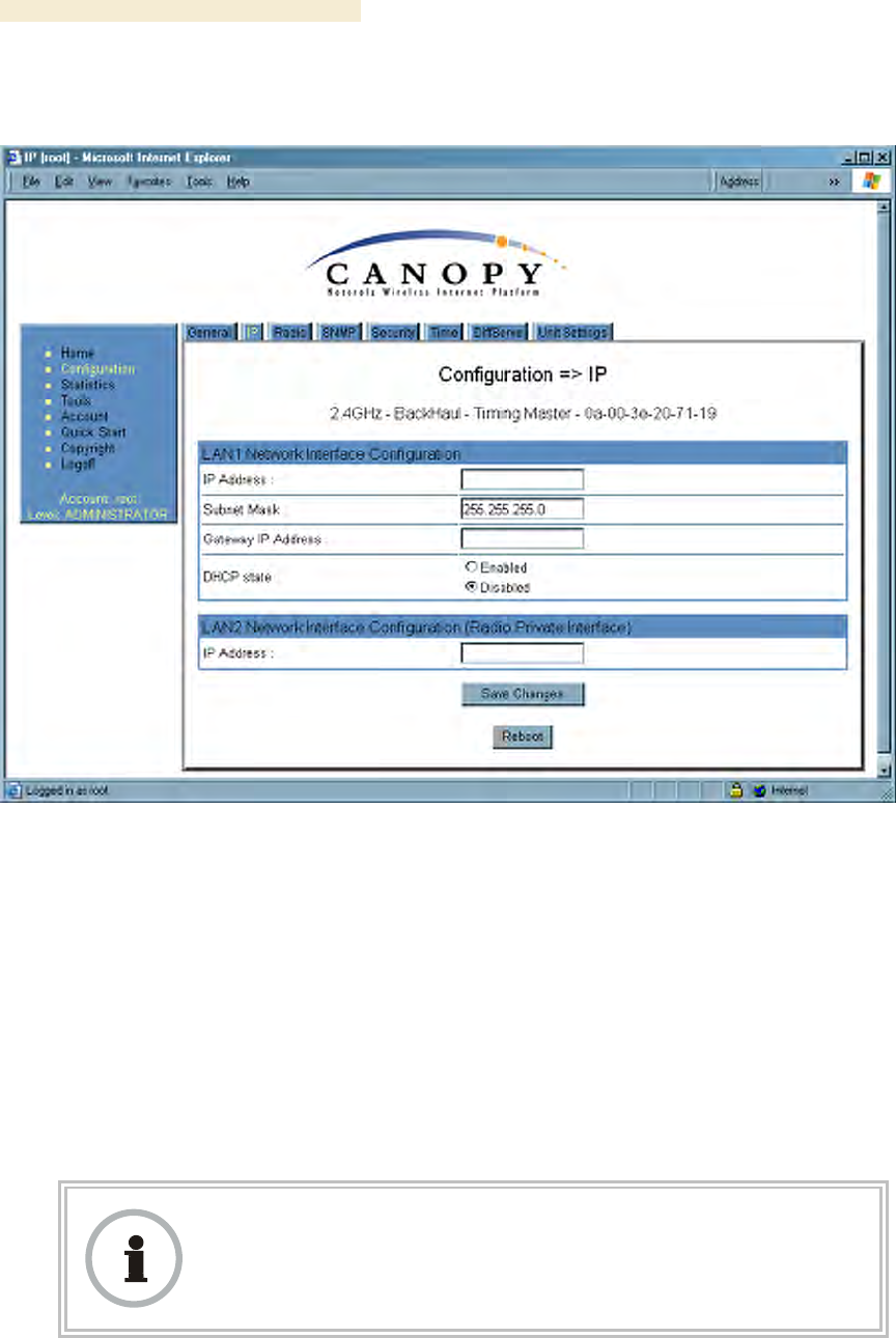
18.4.2 IP Tab of the BHM
An example of an IP tab in a BHM is displayed in Figure 107.
Figure 107: IP tab of BHM, example
You may set the following IP Configuration page parameters.
LAN1 Network Interface Configuration, IP Address
Enter the non-routable IP address to be associated with the Ethernet connection on this
module. (The default IP address from the factory is 169.254.1.1.) If you set and then
forget this parameter, then you must both
1. physically access the module.
2. use an override plug to electronically access the module configuration
parameters at 169.254.1.1. See Overriding Forgotten IP Addresses or
Passwords on AP, SM, or BH on Page 377.
RECOMMENDATION:
Note or print the IP settings from this page. Ensure that you can readily
associate these IP settings both with the module and with the other data that you
store about the module.

Release 8 Installation and Configuration Guide
Issue 2, December 2006 Draft 2 for Regulatory Review 299
LAN1 Network Interface Configuration, Subnet Mask
Enter an appropriate subnet mask for the BHM to communicate on the network. The
default subnet mask is 255.255.0.0. See Allocating Subnets on Page 162.
LAN1 Network Interface Configuration, Gateway IP Address
Enter the appropriate gateway for the BHM to communicate with the network. The default
gateway is 169.254.0.0.
LAN1 Network Interface Configuration, DHCP State
If you select Enabled, the DHCP server automatically assigns the IP configuration
(IP address, subnet mask, and gateway IP address) and the values of those individual
parameters (above) are not used. The setting of this DHCP state parameter is also
viewable, but not settable, in the Network Interface tab of the Home page.
LAN2 Network Interface Configuration (RF Private Interface), IP Address
Enter the IP address to be associated with this BHM for over-the-air access.
The IP tab also provides the following buttons.
Save Changes
When you click this button, any changes that you made on the IP Configuration page are
recorded in flash memory. However, these changes do not apply until the next reboot of
the module.
Reboot
When you click this button
1. the module reboots.
2. any changes that you saved by a click of the Save Changes button are
implemented.
Installation and Configuration Guide Release 8
300 Draft 2 for Regulatory Review Issue 2, December 2006
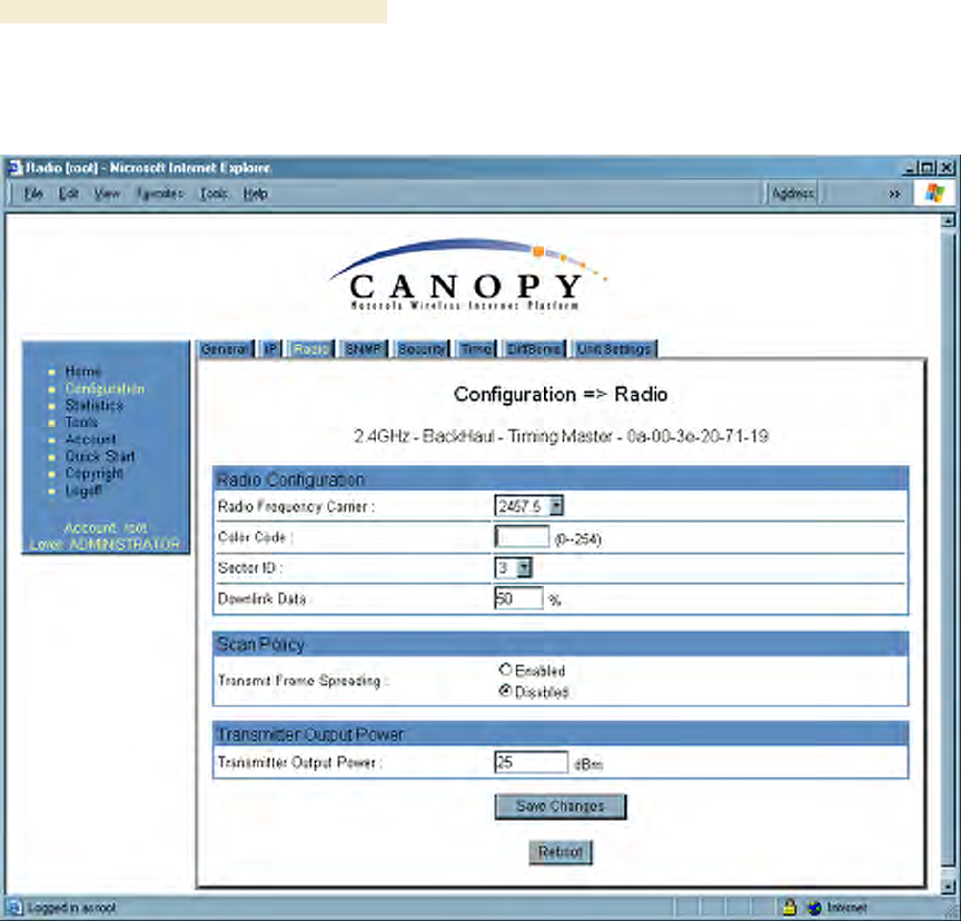
18.4.3 Radio Tab of the BHM
An example of the Radio tab in a BHM is displayed in Figure 108.
Figure 108: Radio tab of BHM, example
In the Radio tab of the BHM, you may set the following parameters.
Radio Frequency Carrier
Specify the frequency for the BHM to transmit. The default for this parameter is None.
(The selection labeled Factory requires a special software key file for implementation.)
In a 5.7-GHz BHM, this parameter displays both ISM and U-NII frequencies. In a 5.2-GHz
BHM, this parameter displays only ISM frequencies. For a list of channels in the band,
see Considering Frequency Band Alternatives on Page 136.
Color Code
Specify a value from 0 to 254. For registration to occur, the color code of the BHM and
the BHS must match. On all Canopy modules, the default setting for the color code value
is 0. This value matches only the color code of 0 (not all 255 color codes).