Motorola Solutions 89FT7623 5400xxyyzzab User Manual Operations guide pt 3c
Motorola Solutions, Inc. 5400xxyyzzab Operations guide pt 3c
Contents
Operations guide pt 3c
Release 8 Installation and Configuration Guide
Issue 2, December 2006 Draft 2 for Regulatory Review 353
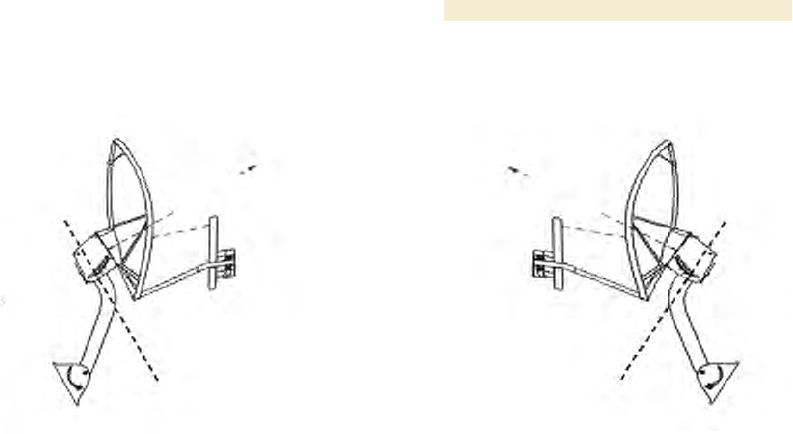
Improper dish, tube, and module positions for this case are illustrated in Figure 139.
--------------------------------------------EARTH--------------------------------------------
Figure 139: Incorrect mount with reflector dish
19.9.2 Modules Mounted at Different Elevations
For cases where the other module in the link is mounted at a different elevation, the
assembly hardware allows tilt adjustment. The proper angle of tilt can be calculated as a
factor of both the difference in elevation and the distance that the link spans. Even in this
case, a plumb line and a protractor can be helpful to ensure the proper tilt. This tilt is
typically minimal.
The number of degrees to offset (from vertical) the mounting hardware leg of the support
tube is equal to the angle of elevation from the lower module to the higher module (b in
the example provided in Figure 40 on Page 145).
19.9.3 Mounting Assembly
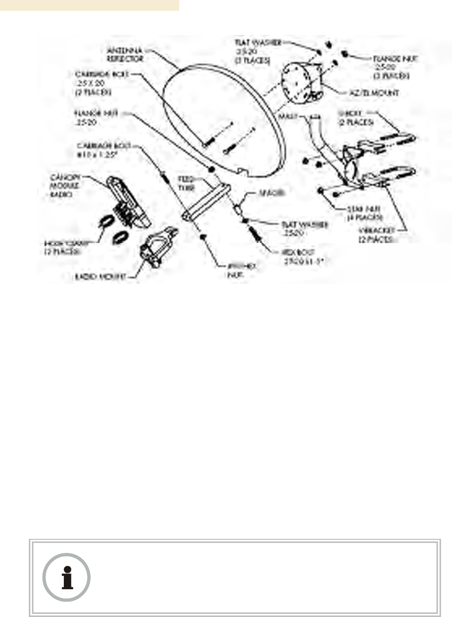
Both the hardware that Mounting Assembly 27RD provides for adjustment and the
relationship between the offset angle of the module and the direction of the beam are
illustrated in Figure 140.
Installation and Configuration Guide Release 8
354 Draft 2 for Regulatory Review Issue 2, December 2006
Figure 140: Mounting assembly, exploded view
19.10 INSTALLING A BH TIMING MASTER
To install the Canopy BHM, perform the following steps:
Procedure 30: Installing the BHM
1. Access the General tab of the Configuration page in the BHM.
2. If this is a 20-Mbps BH, set the 2X Rate parameter to Disabled (temporarily for
easier course aiming).
3. Click the Save Changes button.
4. Click the Reboot button.
5. After the reboot is completed, remove power from the BHM.
6. Choose the best mounting location for your particular application.
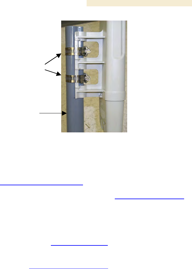
7. Attach the BHM to the arm of the Canopy Passive Reflector dish assembly as
shown in Figure 141.
RECOMMENDATION:
The arm is molded to receive and properly aim the module relative to the aim of
the dish. ( See Figure 138 on Page 352.) Stainless steel hose clamps should be
used for the attachment.
Release 8 Installation and Configuration Guide
Issue 2, December 2006 Draft 2 for Regulatory Review 355
Stainless steel
hose clamps
Reflector dish arm
Figure 141: BH attachment to reflector arm
8. Align the BHM as follows:
a. Move the module to where the link will be unobstructed by the radio horizon
and no objects penetrate the Fresnel zone. (The Canopy System Calculator
page AntennaElevationCalcPage.xls automatically calculates the minimum
antenna elevation that is required to extend the radio horizon to the other end
of the link. The Canopy System Calculator page FresnelZoneCalcPage.xls
automatically calculates the Fresnel zone clearance that is required between
the visual line of sight and the top of a high-elevation object.)
b. Use a local map, compass, and/or GPS device as needed to determine the
direction to the BHS.
c. Apply the appropriate degree of downward or upward tilt. (The Canopy
System Calculator page DowntiltCalcPage.xls automatically calculates the
angle of antenna downward tilt that is required.)
d. Ensure that the BHS is within the beam coverage area. (The Canopy System
Calculator page BeamwidthRadiiCalcPage.xls automatically calculates the
radii of the beam coverage area.)
9. Using stainless steel hose clamps or equivalent fasteners, lock the BHM into
position.
10. Remove the base cover of the BHM. (See Figure 52 on Page 178.)
11. If this BHM will not be connected to a CMMmicro, optionally connect a utility
cable to a GPS timing source and then to the RJ-11 port of the BHM.
12. Either connect the BHM to the CMM or connect the DC power converter to the
BHM and then to an AC power source.
RESULT: When power is applied to a Canopy module or the unit is reset on the
web-based interface, the module requires approximately 25 seconds to boot.
During this interval, self-tests and other diagnostics are being performed.
13. Access the General tab of the Configuration page of this BHM.
14. If the CMM is a CMMmicro, set the Sync Input parameter to the Sync
to Received Signal (Power Port) selection.
If the CMM is a CMM2, set the Sync Input parameter to the Sync to Received
Signal (Timing Port) selection.
=========================== end of procedure ===========================
Installation and Configuration Guide Release 8
356 Draft 2 for Regulatory Review Issue 2, December 2006
19.11 INSTALLING A BH TIMING SLAVE
Installing a Canopy BHS consists of two procedures:
◦ Physically installing the BHS and performing a course alignment using the
alignment tone (Procedure 31).
◦ Verifying the BH link and finalizing alignment using review of power level and
jitter, link tests, and review of registration and session counts (Procedure 32 on
Page 357).
Procedure 31: Installing the BHS
1. Choose the best mounting location for the BHS.
2. Remove the base cover of the BHS. (See Figure 52 on Page 178.)
3. Terminate the UV outside grade Category 5 Ethernet cable with an RJ-45
connector, and connect the cable to the BHS. (See Procedure 8 on Page 192.)
4. Attach the BHS to the arm of the Canopy Passive Reflector dish assembly as
shown in Figure 133 on Page 346.
RECOMMENDATION:
The arm is molded to receive and properly aim the BH relative to the
aim of the dish. Use stainless steel hose clamps for the attachment.
5. Use stainless steel hose clamps or equivalent fasteners to lock the BHS into
position.
6. Remove the cover of the 300SS Surge Suppressor.
7. With the cable openings facing downward, mount the 300SS as close to the
grounding system (Protective Earth) as possible.
8. Using diagonal cutters or long nose pliers, remove the knockouts that cover the
cable openings to the 300SS.
9. Connect an Ethernet cable from the power adapter to either RJ-45 port of the
300SS.
10. Connect another Ethernet cable from the other RJ-45 port of the 300SS to the
Ethernet port of the BHS.
11. Refer to Grounding SMs on Page 172.
12. Wrap an AWG 10 (or 6mm2) copper wire around the Ground post of the 300SS.
13. Tighten the Ground post locking nut in the 300SS onto the copper wire.
14. Securely connect the copper wire to the grounding system (Protective Earth)
according to applicable regulations.
15. Connect a ground wire to the 300SS.
16. Replace the cover of the 300SS surge suppressor.
17. For coarse alignment of the BHS, use the Audible Alignment Tone feature as
follows:
a. If the Configuration web page of the BHS contains a 2X Rate parameter, set
it to Disable.

Release 8 Installation and Configuration Guide
Issue 2, December 2006 Draft 2 for Regulatory Review 357
b. At the BHS, connect the RJ-11 6-pin connector of the Alignment Tool
Headset (shown in Figure 136 on Page 349) to the RJ-11 utility port of the
SM.
Alternatively, instead of using the Alignment Tool Headset, use an earpiece
or small battery-powered speaker connected to Pin 5 (alignment tone output)
and Pin 6 (ground) of an RJ-11 connector.
c. Listen to the alignment tone for
◦ pitch, which indicates greater signal power (RSSI/dBm) by higher
pitch.
◦ volume, which indicates better signal quality (lower jitter) by higher
volume.
d. Adjust the module slightly until you hear the highest pitch and highest
volume.
e. If the Configuration web page of the BHS contains a 2X Rate parameter, set
it back to Enable.
18. When you have achieved the best signal (highest pitch, loudest volume), lock the
BHS in place with the mounting hardware.
=========================== end of procedure ===========================
19.12 UPGRADING A BH LINK TO BH20
To replace a pair of 10-Mbps BHs with 20-Mbps BHs, you can minimize downtime by
temporarily using the 10-Mbps capability in the faster modules. However, both
interference and differences in receiver sensitivity can make alignment and link
maintenance more difficult than in the previous 10-Mbps link. The effects of these factors
are greater at greater link distances, particularly at 5 miles or more.
In shorter spans, these factors may not be prohibitive. For these cases, set the first
replacement module to 1X Rate and establish the link to the 10-Mbps BH on the far end.
Similarly, set the second replacement module to 1X Rate and re-establish the link. With
both of the faster modules in place and with an operational link having been achieved,
reset their modulation to 2X Rate (20 Mbps).
19.13 VERIFYING A BH LINK
To verify the backhaul link after the BHS has been installed, perform the following steps.
Procedure 32: Verifying performance for a BH link
1. Using a computer (laptop, desktop, PDA) connected to the BHS, open a browser
and access the BHS using the default IP address of http://169.254.1.1 (or the IP
address configured in the BHS, if one has been configured.)
2. On the General Status tab of the Home page in the BHS (shown in Figure 71 on
Page 210), look for Power Level and Jitter.
IMPORTANT: The received Power Level is shown in dBm and should be
maximized. Jitter should be minimized. However, better/lower jitter should be
favored over better/higher dBm. For example, if coarse alignment gives a BHS
a power level of −75 dBm and a jitter measurement of 5, and further refining
the alignment drops the power level to −78 dBm and the jitter to 2 or 3, the latter
would be better, with the following caveats:
◦ When the receiving link is operating at 1X, the Jitter scale is 0 to 15 with
desired jitter between 0 and 4.
Installation and Configuration Guide Release 8
358 Draft 2 for Regulatory Review Issue 2, December 2006
◦ When the receiving link is operating at 2X, the Jitter scale is 0 to 15 with
desired jitter between 0 and 9.
NOTE:
For historical reasons, RSSI is also shown and is the unitless
measure of power. The best practice is to use Power Level and
ignore RSSI, which implies more accuracy and precision than is
inherent in its measurement.
3. Fine-adjust the BHS mounting, if needed, to improve Jitter or Power Level.
4. Click the Link Capacity Test tab of the Tools web page in the BHS.
NOTE: Use of this tool is described under Using the Link Capacity Test Tool (All)
on Page 434.
5. Perform several link tests of 10-second duration as follows:
a. Type into the Duration field how long (in seconds) the RF link should be
tested.
b. Leave the Packet Length field (when present) set to the default of 1522
bytes or type into that field the packet length at which you want the test
conducted.
c. Leave the Number of Packets field set to 0 (to flood the link).
d. Click the Start Test button.
e. View the results of the test.
6. If these link tests fail to consistently show 90% or greater efficiency in 1X
operation or 50 to 60% efficiency in 2X, troubleshoot the link, using the data as
follows:
◦ If the downlink is consistently 90% efficient, but the uplink is only 40%, this
indicates trouble for the BHS transmitting to the BHM. Investigate a possible
source of interference near the BHM.
◦ If the uplink is consistently 90% efficient, but the downlink is only 40%, this
indicates trouble for the BHM transmitting to the BHS. Investigate a possible
source of interference near the BHS.
If these link tests consistently show 90% or greater efficiency in 1X operation, or
50 to 60% efficiency in 2X operation, in both uplink and downlink, continue this
procedure.
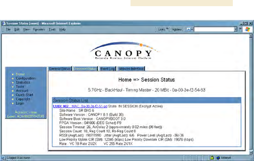
7. Open the Session Status tab in the Home page of the BHM.
NOTE: An example of this page is shown in Figure 142.
Release 8 Installation and Configuration Guide
Issue 2, December 2006 Draft 2 for Regulatory Review 359
Figure 142: Session Status tab of BHM
8. Find the Session Count line under the MAC address of the BHS.
9. Check and note the values for Session Count, Reg Count, and Re-Reg Count.
10. Briefly monitor these values, occasionally refreshing this page by clicking another
tab and then the Session Status tab again.
11. If these values are low (for example, 1, 1, and 0, respectively, meaning that
the BHS registered and started a stable session once) and not changing
a. consider the installation successful.
b. monitor these values from the network office over the next several hours and
days.
If these values are greater than 1, 1, and 0, or they increase while you are
monitoring them, troubleshoot the link. (For example, recheck jitter as described
in Procedure 28: Installing the SM or recheck link efficiency as described in this
procedure, then look for sources of RF interference or obstructions.)
=========================== end of procedure ===========================

Release 8 Installation and Configuration Guide
Issue 2, December 2006 Draft 2 for Regulatory Review 361
20 VERIFYING SYSTEM FUNCTIONALITY
To verify system functionality after the APs and or BHs have been installed, perform the
following steps.
Procedure 33: Verifying system functionality
1. For each installed AP, use a computer or PDA connected to an SM set to a
compatible configuration (frequency and color code, for example) and verify link
functionality.
2. For each BH installed, use a notebook computer connected to a BH (BHM or
BHS, as appropriate) set to a compatible configuration and verify link
functionality.
3. If a network data feed is present and operational, use an SM or BHS to verify
network functionality.
=========================== end of procedure ===========================

Release 8 Operations Guide
Issue 2, December 2006 Draft 2 for Regulatory Review 363
O
OPERATIONS
PERATIONS
G
GUIDE
UIDE
Release 8 Operations Guide
Issue 2, December 2006 Draft 2 for Regulatory Review 365
21 GROWING YOUR NETWORK
Keys to successfully growing your network include
◦ monitoring the RF environment.
◦ considering software release compatibility.
◦ redeploying modules appropriately and quickly.
21.1 MONITORING THE RF ENVIRONMENT
Regardless of whether you are maintaining or growing your network, you may encounter
new RF traffic that can interfere with your current or planned equipment. Regularly
measuring over a period of time and logging the RF environment, as you did before you
installed your first equipment in an area, enables you to recognize and react to changes.
21.1.1 Spectrum Analyzer
IMPORTANT!
The following sections describe the use of a Canopy module in scan mode to
analyze the RF spectrum. While a module is in the scan mode, no RF
connectivity to that module is possible until either you click Disable on the
Spectrum Analyzer page or 15 minutes elapses since the module entered the
scan mode.
For this reason
◦ do not enable the spectrum analyzer from an RF-connected module.
(No readings will be displayed when the RF connection is re-
established.)
◦ be advised that, if you enable the spectrum analyzer by Ethernet
connection, any current RF connection to that module drops.
You can use any AP, SM, or BHS to see at once the frequency and power level of any
detectable signal that is within, above, or below the frequency band range of the module.
RECOMMENDATION:
Vary the days and times when you analyze the spectrum in an area.
The RF environment can change throughout the day or throughout the week.
Temporarily deploy an SM or BHS for each frequency band range that you need to
monitor and access the Spectrum Analyzer tab in the Tools web page of the module.
(For access from a PDA, see PDA Access to Canopy Modules on Page 331.) To enter
the scan mode and view readings, click Enable.
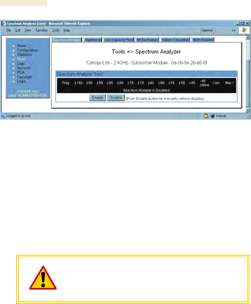
21.1.2 Graphical Spectrum Analyzer Display
An SM/BHS displays the graphical spectrum analyzer. An example of the Spectrum
Analyzer tab is shown in Figure 143.
Operations Guide Release 8
366 Draft 2 for Regulatory Review Issue 2, December 2006
Figure 143: Spectrum Analyzer tab of SM, example
Colors in the display have the following meanings:
◦ Green bars show the most recent measurements.
◦ Yellow ticks show the maximum measurements from the current spectrum
analysis session.
◦ Red ticks show measurements of −40 dBm or stronger.
To keep the displayed data current, either set this page to automatically refresh or
repeatedly click the Enable button. When you are finished analyzing the spectrum, click
the Disable button to return the module to normal operation.
21.1.3 Using the AP as a Spectrum Analyzer
You can temporarily transform an AP into an SM and thereby use the spectrum analyzer
functionality. This is the only purpose supported for the transformation.
CAUTION!
You lose connectivity to the AP during spectrum analysis, have no service to
any SMs that are connected to it, and can regain connectivity (and toggle it
back to AP) through only the wired Ethernet interface to the AP. For this
reason, you should perform the transformation to SM in the Ethernet interface.
To transform the AP into an SM for spectrum analysis and then return the device to
an AP, perform the following steps.
Procedure 34: Using the Spectrum Analyzer in AP feature
1. Connect to the wired Ethernet interface of the AP.
2. Access the General tab of the Configuration page in the AP.
3. Set the Device Setting parameter to SM.
4. Click the Save Changes button.
5. Click the Reboot button.

Release 8 Operations Guide
Issue 2, December 2006 Draft 2 for Regulatory Review 367
6. When the module has rebooted as an SM, click the Tools navigation link on the
left side of the Home page.
7. Click the Spectrum Analyzer tab.
8. Either set this page to automatically refresh or repeatedly click the Enable
button.
RESULT: The SM enters the scan mode.
9. When you are finished analyzing the spectrum, click the Disable button.
10. In the left-side navigation links, click Configuration.
11. Click the General tab.
12. Set the Device Setting parameter to AP.
13. Click the Save Changes button.
14. Click the Reboot button.
RESULT: The AP boots with its previous frequency setting.
=========================== end of procedure ===========================
21.2 CONSIDERING SOFTWARE RELEASE COMPATIBILITY
Within the same Canopy network, modules can operate on multiple software releases.
However, the features that can be enabled are limited to those that the earliest software
supports.
21.2.1 Designations for Hardware in Radios
Canopy documentation refers to hardware series (for example, Series P9). Canopy
Release 8 requires APs, BHs, and AES SMs to be Series P9 or later hardware.
The correlation between hardware series and the MAC addresses of the radio modules
is provided in Table 56.
Table 56: Hardware series by MAC address
Hardware Series
Radio
Frequency
Band
Range
P7 or P8
in These MAC
Addresses
P9 or Later
in These MAC
Addresses
900
None
All
2.4
≤ 0A003E20672B
≥ 0A003E20672C
5.2
≤ 0A003E00F4E3
≥ 0A003E00F4E4
5.4
None
All
5.7
≤ 0A003EF12AFE
≥ 0A003EF12AFF
Differences in capabilities among these hardware series are summarized in Table 57.
Table 57: Hardware series differences
Availability per
Hardware Series
Capability
P7
P8
P9
Auto-sense Ethernet cable scheme
no
yes
yes

Operations Guide Release 8
368 Draft 2 for Regulatory Review Issue 2, December 2006
Support CMMmicro
no
yes
yes
Support hardware scheduling in APs1
no
no
yes
Support 2X operation in APs and SMs
no
no
yes
NOTES:
1. An SM of P7 or P8 series requires an FPGA load through
CNUT for access to hardware scheduling, and then only
at 1X operation. An AP of P7 or P8 series cannot perform
hardware scheduling.
Advantage Series P9 APs provide higher throughput and lower latency than earlier series
Advantage APs and support configuring the high-priority channel per SM. Regular
Canopy Series P9 APs do not provide the higher throughput and lower latency, but they
do support configuring the high-priority channel per SM.
21.2.2 CMMmicro Software and Hardware Compatibility
The CMMmicro contains both a programmable logic device (PLD) and software. These
must be compatible. For example, the PLD that is compatible with CMMmicro Release
2.0.8 is PLD 5. Further, the CMMmicro must be compatible with both the application
software release and the hardware of attached APs and BHs. These attached modules
must have been manufactured in October 2002 or later.
APs and BHs that were manufactured earlier do not support sync on the power leads of
the Ethernet port. To determine whether the AP or BH hardware is compatible with the
CMMmicro, see Table 58.
Table 58: AP/BH compatibility with CMMmicro
Range of MAC Addresses (ESNs)
Frequency
Band
Range
Incompatible
with CMMmicro
Compatible
with CMMmicro
900 MHz AP
none
all
2.4 GHz
none
all
5.2 GHz
≤ 0A003E0021C8
≥ 0A003E0021C9
5.4 GHz
none
all
5.7 GHz
≤ 0A003EF00F79
≥ 0A003EF00F7A
21.2.3 MIB File Set Compatibility
Although MIB files are text files (not software), they define objects associated with
configurable parameters and indicators for the module and its links. In each release,
some of these parameters and indicators are not carried forward from the previous
release, and some parameters and indicators are introduced or changed.
For this reason, use the MIB files from your download to replace previous MIB files in
conjunction with your software upgrades, even if the file names are identical to those of
your previous files. Date stamps on the MIB files distinguish the later set.

Release 8 Operations Guide
Issue 2, December 2006 Draft 2 for Regulatory Review 369
21.3 REDEPLOYING MODULES
Successfully redeploying a module may involve
◦ maintaining full and accurate records of modules being redeployed from
warehouse stock.
◦ exercising caution about
− software compatibility. For example, whether desired features can be
enabled with the redeployed module in the network.
− procedural handling of the module. For example
◦ whether to align the SM or BHS by power level and jitter or by only jitter.
◦ whether the module auto-senses the Ethernet cable connector scheme.
− hardware compatibility. For example, where a CMMmicro is deployed.
− the value of each configurable parameter. Whether all are compatible in the
new destination.
◦ remembering to use auto discovery to add the redeployed SM to the network
in Prizm.
21.3.1 Wiring to Extend Network Sync
The following procedure can be used to extend network sync by one additional hop, as
described under Passing Sync in an Additional Hop on Page 97. Where a collocated
module receives sync over the air, the collocated modules can be wired to pass the sync
as follows:
Procedure 35: Extending network sync
1. Connect the GPS Utility ports of the collocated modules using a sync cable with
RJ-11 connectors.
2. Set the Sync Input parameter on the Configuration page of the collocated AP or
BH timing master to Sync to Received Signal (Timing Port).
3. Set the Frame Timing Pulse Gated parameter on the Configuration page of the
collocated SM or BH timing slave to Enable.
NOTE: This setting prevents interference in the event that the SM or BH timing
slave loses sync.
=========================== end of procedure ===========================

Release 8 Operations Guide
Issue 2, December 2006 Draft 2 for Regulatory Review 371
22 SECURING YOUR NETWORK
22.1 ISOLATING APS FROM THE INTERNET
Ensure that the IP addresses of the APs in your network
◦ are not routable over the Internet.
◦ do not share the subnet of the IP address of your user.
RFC 1918, Address Allocation for Private Subnets, reserves for private IP networks three
blocks of IP addresses that are not routable over the Internet:
◦ /8 subnets have one reserved network, 10.0.0.0 to 10.255.255.255.
◦ /16 subnets have 16 reserved networks, 172.16.0.0 to 172.31.255.255.
◦ /24 subnets have 256 reserved networks, 192.168.0.0 to 192.168.255.255.
22.2 ENCRYPTING CANOPY RADIO TRANSMISSIONS
Canopy systems employ the following forms of encryption for security of the wireless link:
◦ BRAID–a security scheme that the cellular industry uses to authenticate wireless
devices.
◦ DES–Data Encryption Standard, an over-the-air link option that uses secret
56-bit keys and 8 parity bits.
◦ AES–Advanced Encryption Standard, an extra-cost over-the-air link option that
provides extremely secure wireless connections. AES uses 128-bit secret keys
as directed by the government of the U.S.A. AES is not exportable and requires
a special AP to process the large keys.
BRAID is a stream cipher that the TIA (Telecommunications Industry Association) has
standardized. Standard Canopy APs and SMs use BRAID encryption to
◦ calculate the per-session encryption key (independently) on each end of a link.
◦ provide the digital signature for authentication challenges.
22.2.1 DES Encryption
Standard Canopy modules provide DES encryption. DES performs a series of bit
permutations, substitutions, and recombination operations on blocks of data.
DES Encryption does not affect the performance or throughput of the system.
22.2.2 AES Encryption
Motorola also offers Canopy products that provide AES encryption. AES uses the
Rijndael algorithm and 128-bit keys to establish a higher level of security than DES.
Because of this higher level of security, the government of the U.S.A. controls the export
of communications products that use AES (among which the Canopy AES feature
activation key is one) to ensure that these products are available in only certain regions
and by special permit.

Operations Guide Release 8
372 Draft 2 for Regulatory Review Issue 2, December 2006
The Canopy distributor or reseller can advise service providers about current regional
availability. Canopy AES products are certified as compliant with the Federal Information
Processing Standards (FIPS) in the U.S.A. The National Institute of Standards and
Technology (NIST) in the U.S.A. has specified AES for significantly greater security than
that which DES provides. NIST selected the AES algorithm for providing the best
combination of security, performance, efficiency, implementation, and flexibility. NIST
collaborates with industry to develop and apply technology, measurements, and
standards.
22.2.3 AES-DES Operability Comparisons
This section describes the similarities and differences between DES and AES products,
and the extent to which they may interoperate.
The DES AP and the DES BHM modules are factory-programmed to enable or disable
DES encryption. Similarly, the AES AP and the AES BHM modules are factory-
programmed to enable or disable AES encryption. In either case, the authentication key
entered in the Configuration page establishes the encryption key. For this reason,
the authentication key must be the same on each end of the link. See Authentication Key
on Page 283.
Feature Availability
Canopy AES products run the same software as DES products. Thus feature availability
and functionality are and will continue to be the same, regardless of whether AES
encryption is enabled. All interface screens are identical. However, when encryption
is enabled on the Configuration screen
◦ the AES product provides AES encryption.
◦ the DES product provides DES encryption.
Canopy AES products and DES products use different FPGA (field-programmable gate
array) loads. However, the AES FPGA will be upgraded as needed to provide new
features or services similar to those available for DES products.
Canopy DES products cannot be upgraded to AES. To have the option of AES
encryption, the operator must purchase AES products.
Interoperability
Canopy AES products and DES products do not interoperate when enabled for
encryption. For example, An AES AP with encryption enabled cannot communicate with
DES SMs. Similarly, an AES Backhaul timing master module with encryption enabled
cannot communicate with a DES Backhaul timing slave module.
However, if encryption is disabled, AES modules can communicate with DES modules.
Release 8 Operations Guide
Issue 2, December 2006 Draft 2 for Regulatory Review 373
22.3 MANAGING MODULE ACCESS BY PASSWORDS
22.3.1 Adding a User for Access to a Module
From the factory, each Canopy module has a preconfigured administrator-level account
in the name root, which initially requires no associated password. This is the same
root account that you may have used for access to the module by telnet or ftp.
If you upgrade a module to Release 8
◦ an account is created in the name admin.
◦ both admin and root inherit the password that was previously used for access
to the module:
− the Full Access password, if one was set.
− the Display-Only Access password, if one was set and no Full Access
password was set.
IMPORTANT!
If you use Prizm, do not delete the root account from any module. If you use an
NMS that communicates with modules through SNMP, do not delete the root
account from any module unless you first can confirm that the NMS does not rely
on the root account for access to the modules.
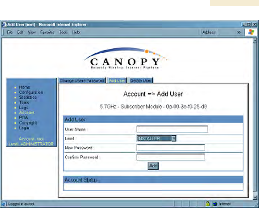
Each module supports four or fewer user accounts, regardless of account levels. The
available levels are
◦ ADMINISTRATOR, who has full read and write permissions. This is the level of
the root and admin users, as well as any other administrator accounts that one
of them creates.
◦ INSTALLER, who has permissions identical to those of ADMINISTRATOR
except that the installer cannot add or delete users or change the password of
any other user.
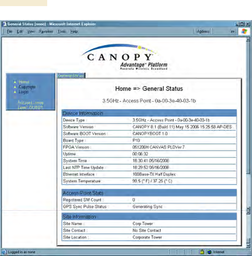
◦ GUEST, who has no write permissions and only a limited view of General Status
tab, as shown in Figure 144, and can log in as a user.
Operations Guide Release 8
374 Draft 2 for Regulatory Review Issue 2, December 2006
Figure 144: General Status tab view for GUEST-level account
An example of the Add User tab is displayed in Figure 145.
Release 8 Operations Guide
Issue 2, December 2006 Draft 2 for Regulatory Review 375
Figure 145: Add User tab of SM, example
After a password has been set for any ADMINISTRATOR-level account, initial access to
the module GUI opens the view of GUEST level (Figure 144).
Accounts that cannot be deleted are
◦ the current user's own account.
◦ the last remaining account of ADMINISTRATOR level.
22.3.2 Overriding Forgotten IP Addresses or Passwords on AP, SM, or BH
Canopy systems offer a plug that allows you to temporarily override some AP/SM/BH
settings and thereby regain control of the module. This plug is needed for access to the
module in any of the following cases:
◦ You have forgotten either
− the IP address assigned to the module.
− the password that provides access to the module.
◦ The module has been locked by the No Remote Access feature. (See Denying
All Remote Access on Page 453 and Reinstating Remote Access Capability on
Page 453.)
◦ You want local access to a module that has had the 802.3 link disabled in the
Configuration page.
You can configure the module such that, when it senses the override plug, it responds by
either