Motorola Solutions 89FT7623 Canopy 5400 Fixed Wireless Transceiver User Manual Release10 5FCCdraft2
Motorola Solutions, Inc. Canopy 5400 Fixed Wireless Transceiver Release10 5FCCdraft2
Contents
- 1. Operations guide pt 1
- 2. operations guide pt 2
- 3. Operations guide pt 2a
- 4. Operations guide pt 3a
- 5. Operations guide pt 3b
- 6. Operations guide pt 3c
- 7. Operations guide pt 3d
- 8. Updated Professional install instructions
Updated Professional install instructions

FCC Draft
Software Release 10.5
Release Notes and User Guide
Supplement
PMP 100 and PTP 100 (FSK)
PMP 400 and PTP 200 (OFDM)
FCC Draft
November 2010

FCC Draft
Notices
See important regulatory and legal notices in Section 10 on Page 31.
Trademarks, Product Names, and Service Names
MOTOROLA, the stylized M Logo, Canopy, and all other trademarks indicated as such herein are
registered trademarks of Motorola, Inc. ® Reg. US Pat & Tm. Office. All other product or service
names are the property of their respective owners.
© 2010 Motorola, Inc. All rights reserved
http://motorola.wirelessbroadbandsupport.com
Release 10.5 Release Notes and User Guide Supplement
FCC Draft, November 2010 Page 3
Table of Contents
1 Introduction .......................................................................................................... 5
1.1 Release 10.5 Overview ................................................................................. 5
1.2 Document Change History ............................................................................ 5
1.3 Abbreviations ................................................................................................ 5
1.4 Feedback on Documentation ........................................................................ 6
1.5 Technical Support ......................................................................................... 6
2 Applicability .......................................................................................................... 8
3 Upgrading to Release 10.5................................................................................... 9
3.1 Obtaining CNUT Upgrade Packages............................................................. 9
3.2 Network Management ................................................................................... 9
3.3 PMP 430 – Options for 5, 10, and 20 MHz Channel Size .............................. 9
4 Features .............................................................................................................. 11
4.1 US - Operation to avoid Interference with TDWR ........................................ 12
5 Resolved Issues .................................................................................................16
6 Known Open Issues ........................................................................................... 17
7 Notes and Reference.......................................................................................... 18
7.1 Notes .......................................................................................................... 18
7.2 US Region Code Operation......................................................................... 21
7.3 PMP 430 Center Channels.......................................................................... 21
7.4 PMP 100 Series DFS Operation Based on Region Code ............................ 23
7.5 PTP 100 Series DFS Operation Based on Region Code............................. 24
7.6 PMP 400/430 and PTP 200 DFS Operation Based on Region Code........... 25
8 Canopy MIB......................................................................................................... 26
9 Performance Benchmarking Process ............................................................... 27
9.1 Definitions ................................................................................................... 27
9.2 System Performance and System Constraints ............................................ 27
9.3 Benchmark Definition .................................................................................. 29
10 Regulatory and Legal Notices........................................................................... 31
10.1 Important Note on Modifications .................................................................31
Release 10.5 Release Notes and User Guide Supplement
FCC Draft, November 2010 Page 4
10.2 National and Regional Regulatory Notices.................................................. 31
10.3 RF Exposure Separation Distances ............................................................ 39
10.4 Legal Notices.............................................................................................. 42
10.5 Limit of Liability........................................................................................... 44
List of Tables
Table 1: Release 10.5 Features ..................................................................................11
Table 2: TDWR Location Information ..........................................................................14
Table 3: Issues resolved in Release 10.5 ....................................................................16
Table 4: Release 10.5 known open issues ..................................................................17
Table 5: Notes first discussed with Release 10.3.1......................................................18
Table 6: Notes first discussed with Release 9.5 ..........................................................19
Table 7: PMP 430 center channels by channel bandwidth and region code ................22
Table 8: PMP 100 (FSK) AP/SM DFS operation based on region code.......................23
Table 9: PTP 100 (FSK) BHM/BHS operation based on region code ..........................24
Table 10: PMP 400/430 and PTP 200 (OFDM) DFS operation based on region code.25
Table 11: US FCC IDs and Industry Canada Certification Numbers and covered
configurations ..............................................................................................32
Table 12: China disclosure table .................................................................................38
Table 13: Exposure separation distances....................................................................39
Table 14: Calculated exposure distances and power compliance margins ..................40
List of Figures
Figure 1: Applicable products ........................................................................................8
Figure 2: PMP AP and PTP BH Region Code Set to United States .............................21
Figure 3: PPS Benchmark Test Setup .........................................................................30
Release 10.5 Release Notes and User Guide Supplement
FCC Draft, November 2010 Page 5
1 Introduction
1.1 RELEASE 10.5 OVERVIEW
Release 10.5 is a general release for all Canopy FSK and OFDM radios, including PMP 100,
PMP 400/430, PTP 100, and PTP 200 Series modules. This document contains release note
information (resolved issues and known open issues) as well as information that supplements the
Motorola PMP Solutions Users Guide (descriptions, procedures, and reference information).
For the US, Release 10.5 and this document supports
o avoiding interfering with Terminal Doppler Weather Radar (TDWR) (used near major
airports) when using the 5.4-GHz band, especially within 35 km (21.75 mi) of the
TDWR
o certification and shipment of US 5.4-GHz PMP 430 (OFDM) APs and SMs
o certification and shipment of US Series P11 5.4-GHz PMP 100 (FSK) APs and SMs
and PTP 100 (FSK) BHs
For details on these and other Release 10.5 features, see section 4 on page 11.
For improvements and issues resolved in Release 10.5, see section 5 on page 16.
For release open issues, see section 6 on page 17.
Modules should be running Release 10.4 before upgrading to Release 10.5.
To manage modules running Release 10.5, including managing features new to this release, use
either Prizm 3.3 or Wireless Manager 2.2.
1.2 DOCUMENT CHANGE HISTORY
FCC Draft
Draft for FCC approval process
1.3 ABBREVIATIONS
The following abbreviations and acronyms are used in these notes and related documentation:
AES Advanced Encryption Standard
AP Access Point
BAM Bandwidth and Authentication Manager
BH Backhaul Module
BHM Backhaul Module – Master
BHS Backhaul Module – Slave
CAP Access Point Module
CEPT Conference of European Post and
Telecommunications
CIR Committed Information Rate
CMM Cluster Management Module
CNUT Canopy Network Updater Tool
CSM Subscriber Module
DES Data Encryption Standard
DFS Dynamic Frequency Selection
DHCP Dynamic Host Configuration Protocol
DNS Domain Name System
EIRP Equivalent Isotropically Radiated Power
EFTA European Free Trade Association
ETSI European Telecommunications
Standards Institute
EU European Union
FAA US Federal Aviation Administration
FCC US Federal Communications
Commission
FSK Frequency Shift Keying
FTP File Transfer Protocol
FTPS Secure FTP
GPS Global Positioning System
HPAP High Performance AP (PMP 430 AP)
IC Industry Canada
IETF Internet Engineering Task Force
IP Internet Protocol
ISM Industrial, Scientific, Medical
LAN Local Access Network

Release 10.5 Release Notes and User Guide Supplement
FCC Draft, November 2010 Page 6
MAC Media Access Controller
MIB Management Information Base
MIR Maximum Information Rate
NAT Network Address Translation
NTIA National Telecommunications and
Information Administration
OFDM Orthogonal Frequency Division
Multiplexing
OID SNMP Object Identifier
P7/P8/P9/P10/P11 Hardware Series
PMP Point to Multi-Point
PTP Point to Point
RADIUS Remote Authentication Dial In User
Service
RF Radio Frequency
RLAN Radio Local Area Network
SM Subscriber Module
SNMP Simple Network Management Protocol
SNR Signal to Noise Ratio
TCP/IP Transmission Control Protocol/Internet
Protocol
VDC Volts Direct Current
VID VLAN ID
VLAN Virtual LAN
WAN Wide Area Network
WISPA Wireless Internet Service Providers
Association
WM One Point Wireless Manager
1.4 FEEDBACK ON DOCUMENTATION
Is this document accurate, complete, and clear? How can it be improved? Please send your
feedback on Canopy documentation to technical-documentation@canopywireless.com.
1.5 TECHNICAL SUPPORT
Tip! Do not clear the Event Log after you encounter issues. It may be useful to
Technical Support, if you need to escalate the issue.
Here is the escalation path for resolution of a problem:
1. Check documentation:
These Release Notes
Motorola PMP Solutions Users Guide, available at
http://motorola.wirelessbroadbandsupport.com/software.
2. Consider checking the Community Forum and Knowledge Base at
http://motorola.wirelessbroadbandsupport.com/support/community.
3. Consider checking the Support Home Page at
http://motorola.wirelessbroadbandsupport.com/support/technical.php
4. Escalate the problem to your supplier or reseller.
5. Escalate the problem to Technical Support or other designated Tier 3 technical
support:
Email: EMS-EICC-RM@motorola.com
Phone:
U.S. and Canada 1-866-961-9288
Europe, Middle East, and Africa
Denmark 043682114
France 0157323434
Germany 06950070204
Italy 0291483230
Lithuania 880 030 828
Netherlands 0202061404
Norway 24159815
Portugal 0217616160
Spain 0912754787
Russia 810 800 228 41044
Saudi Arabia 800 844 5345
South Africa 0800981900
United Kingdom 0203 0277499
All other countries +420 533 336 946
Release 10.5 Release Notes and User Guide Supplement
FCC Draft, November 2010 Page 7
Latin and Central America
Argentina 0800-666-2789
Brazil 0800-891-4360
Columbia 01-800-912-0557
Mexico 001-800-942-7721
Peru 0800-70-086
All other countries +420 533 336 946
Asia and Pacific
Australia 1 800 457 439
Northern China 10 800 713 0885
Southern China 10 800 130 0867
China, local DID +86 21 6108 6109
Hong Kong 30 027 861
India 000 800 100 3098
Japan 221626765
Japan, PSTN (81) 335 708 643
South Korea 080 681 0880
Malaysia 1 800 812 384
New Zealand 0 800 448 472
Philippines 63 29 003 057
Singapore 64 155 110
Taiwan 00 801 14 8690
Thailand 001 800 441 0950
Indonesia 001 803 015 20 20530
All other countries +420 533 336 946
When you send e-mail or call, please include, as appropriate, software release on each module,
IP addresses, MAC addresses, and features enabled, like NAT, VLAN, high priority channel, or
CIR. You may be asked to run the Support Tool on CNUT or Prizm to provide a complete network
picture.
Release 10.5 Release Notes and User Guide Supplement
FCC Draft, November 2010 Page 8
2 Applicability
Release 10.5 is a general release recommended for all the products shown in Figure 1.
Modulation and
Module Type
PMP Radio Series
(Point-to-MultiPoint)
PTP Radio Series
(Point-To-Point)
PMP 100 Series
PTP 100 Series
Frequencies: 900MHz,
2.4, 5.1, 5.2, 5.4, 5.7,
5.9, 6.050-GHz
Frequencies:
2.4, 5.2, 5.4, 5.7-GHz
FSK
AP/SM/BH
Note: P7 and P8 APs
cannot be upgraded
Note: AES P7 and P8
SMs cannot be upgraded
(All DES SMs can be)
Note: P7 and P8 BHs
cannot be upgraded
PMP 430 Series
N/A
OFDM
AP/SM
Frequencies:
5.4-GHz PMP 54430
5.8-GHz PMP 58430
N/A
PMP 400 Series
PTP 200 Series
OFDM
AP/SM/BH
Frequencies:
4.9-GHz PMP 49400
5.4-GHz PMP 54400
Frequencies:
4.9-GHz PTP 49200
5.4-GHz PTP 54200
Figure 1: Applicable products
Not all products are available in all markets. Please check with your local reseller for availability.

Release 10.5 Release Notes and User Guide Supplement
FCC Draft, November 2010 Page 9
3 Upgrading to Release 10.5
Use version 3.20.13 of the Network Updater Tool (CNUT) to upgrade to Release 10.5.
CNUT and its release notes can be downloaded from the Motorola wireless broadband support
web site: http://motorola.wirelessbroadbandsupport.com/software/
Modules in operating sectors should be on Release 10.4 before upgrading to avoid upgrade
issues.
3.1 OBTAINING CNUT UPGRADE PACKAGES
To download the Canopy software to your computer, perform the following steps:
1. Go to http://motorola.wirelessbroadbandsupport.com/software.
2. Follow the directions on that page to access the software download page.
3. On the software download page, select the appropriate package or packages. Options
include [for betas, use packages provided by technical support]
CANOPY105BUILDOFFICIAL_DES.pkg3
CANOPY105BUILDOFFICIAL_AES.pkg3
CANOPY105BUILDOFFICIAL_OFDM_DES.pkg3
CANOPY105BUILDOFFICIAL_OFDM_AES.pkg3
4. Click Accept User Agreement and Request Download Links.
RESULT: You will receive an email with a link or links to the software.
5. In the email sent to you, click on the desired link or links.
RESULT: The appropriate.pkg3 package or packages will download to your computer.
For additional information on using CNUT, see the CNUT help file or click on the Help menu in
the CNUT application.
3.2 NETWORK MANAGEMENT
Either One Point Wireless Manager or Prizm can be used to manage Motorola PMP and PTP
networks. For additional information, see
One Point Wireless Manager:
(http://motorola.wirelessbroadbandsupport.com/support/opws/software/
Prizm: http://motorola.wirelessbroadbandsupport.com/software/
3.3 PMP 430 – OPTIONS FOR 5, 10, AND 20 MHZ CHANNEL SIZE
PMP 430 APs and SMs ship with a 10-MHz channel size. Using CNUT 3.20.13 this can be
changed to 20 MHz or 5 MHz.
Note for US and Canadian Operators: 5.4-GHz PMP 430 APs and SMs with a US model
number (and a locked Region Code of US) or a Region Code of Canada do not support a 5
MHz channel size, consistent with FCC certification and Industry Canada certification. (5.7-GHz
PMP 430 APs and SMs do include a 5-MHz channel size, consistent with their certifications.)
Changing channel size on an AP requires using CNUT. (CNUT loads the appropriate software
components into the AP.)
Release 10.5 Release Notes and User Guide Supplement
FCC Draft, November 2010 Page 10
Changing channel size on deployed SMs can be done on the SM GUI but is usually better done
using CNUT, as CNUT changes all the SMs in a sector at once.
Changing channel size on an installing SM should be done on the SM GUI.
The AP and the SM must have the same channel size to connect.
Important: In an operating sector, use CNUT to change the channel size of the SMs first, then
the AP. If you change the AP’s channel size first, SMs won’t register to it since the AP and SMs
are operating at different channel sizes. You will have to change the AP back before proceeding.
Important for US and Canadian Operators:
Don’t change 5.4-GHz APs to 5-MHz channel size. CNUT will change a PMP 430 AP to 5-MHz
channel size regardless of the Region Code, but a US or Canada 5.4-GHz PMP 430 AP will boot
with transmit disabled, consistent with its certification, and you will have to change the AP back to
10 MHz or 20 MHz channel size using CNUT before proceeding.
Don’t set 5.4-GHz SMs to 5-MHz channel size. PMP 430 SMs with a Region Code of US or
Canada do not provide the option for a 5-MHz channel. However, if the Region Code isn’t set or
is set to another region, you can set the SM to 5-MHz channel size, but it won’t connect to a US
or Canada AP, and you will need to change it to the same channel size as the AP to connect.
See the CNUT 3.20.13 release notes for specific procedures for setting PMP 430 channel size.

Release 10.5 Release Notes and User Guide Supplement
FCC Draft, November 2010 Page 11
4 Features
Release 10.5 adds the features listed in Table 1.
Table 1: Release 10.5 Features
Regions
Affected
Products
Affected
Feature
Description
See for
Details
US
All 5.4-GHz
5.4-GHz PMP 100
(FSK)
5.4-GHz PTP 100
(FSK)
5.4-GHz PMP 430
(OFDM)
5.4-GHz PMP 400
(OFDM)
5.4-GHz PTP 200
(OFDM)
Operation to avoid
interference with
Terminal Doppler
Weather Radar
(TDWR)
To avoid interference with TDWR (47
locations, near major airports), 5.4-GHz
US radios must
◦ be professionally installed
◦ have a transmit frequency set on
the AP/BHM at least 30 MHz
(center-to-center) from any TDWR
within 35 km (21.75 mi) of the
AP/BHM or any of its SMs/BHS.
http://www.spectrumbridge.com/udia/se
arch.aspx supports the necessary map
analysis and includes a database for
registering the location of these radios
to expedite interference resolution.
Section 4.1
US
US 5.4-GHz PMP
430 (OFDM)
US FCC Certification
of new product
US 5.4-GHz PMP 430 APs and SMs
are now approved for sale in the US.
As certified, the US 5.4-GHz PMP 430
AP is limited to operate at
◦ no higher than 85% Data
Downlink %
◦ 10-MHz and 20-MHz channel
sizes, but not 5-MHz
Lens and reflector were not included in
the certification.
Section 7.6,
Table 10
Section
10.2.1,
Table 11
US
US P11 Hardware
Series 5.4-GHz
PMP 100 (FSK)
US P11 Hardware
Series 5.4-GHz
PTP 100 (FSK)
US FCC Certfication
of new hardware
series
US P11 5.4-GHz PMP 100 APs and
SMs and PTP 100 BHs are now
approved for sale in the US.
As certified, the US P11 PMP 100 AP
and PTP 100 BHM is limited to operate
at
◦ no higher than 75% Data
Downlink %
(Older hardware series are not limited
by Release 10.5.)
Section 7.5,
Table 8,
Table 9
Section
10.2.1,
Table 11
Canada
5.4-GHz PMP 430
(OFDM)
IC Certification of
new product
5.4-GHz PMP 430 APs and SMs are
now approved for sale in Canada.
As certified, the AP is limited to
◦ 10-MHz and 20-MHz channel
sizes, but not 5-MHz
For compliant operation, the Region
Code must be set to Canada by the
professional installer.
Section
10.2.2 and
Table 11

Release 10.5 Release Notes and User Guide Supplement
FCC Draft, November 2010 Page 12
Regions
Affected
Products
Affected
Feature
Description
See for
Details
Canada
P11 Hardware
Series 5.4-GHz
PMP 100 (FSK)
P11 Hardware
Series 5.4-GHz
PTP 100 (FSK)
IC Certfication of new
hardware series
P11 Hardware Series 5.4-GHz PMP
100 APs and SMs and PTP 100 BHs
are now approved for sale in Canada.
For compliant operation, the Region
Code must be set to Canada by the
professional installer.
Section
10.2.2 and
Table 11
4.1 US - OPERATION TO AVOID INTERFERENCE WITH TDWR
The US FCC, NTIA, FAA, and industry are working to resolve interference to Terminal Doppler
Weather Radar (TDWR) systems used near airports that has occurred from some outdoor
wireless systems operating in the 5470 MHz – 5725 MHz band. These wireless devices are
subject to Section 15.407. When operating as a master device they are required to implement
radar detection and DFS functions and radios must not transmit on channels which overlap the
5600-5650 MHz band used by TDWR.
Additional information is available from
o the FCC’s Knowledge Database (KDB) Publication 443999 “Interim Plans to Approve
UNII Devices Operating in the 5470-5725 MHz Band with Radar Detection and DFS
Capabilities” available at https://fjallfoss.fcc.gov/kdb/GetAttachment.html?id=33781
o the Wireless Internet Service Providers Association (WISPA) in coordination with
Spectrum Bridge: http://www.spectrumbridge.com/udia/home.aspx.
5.4-GHz radios must be professionally installed. The professional installer must have the
following expertise:
o Understanding of the configurations outlined in Table 11: US FCC IDs and Industry
Canada Certification Numbers and covered configurations, especially those
applicable to the 5470-5725 MHz U-NII band.
o Understanding of the master/slave operation of the AP/BHM and SM/BHS – that the
AP or BHM determines the transmission frequency for both master and slave.
o Understanding of the SM/BHS frequency scan selection settings and how they can
be set to prevent scanning and therefore transmission on any specific frequencies.
o Understanding of the option to set primary and two alternate frequencies on the AP
or BHM.
o Ability to use the GUI to set the primary and alternate transmit frequencies on an AP
or BHM, scanned frequencies on an SM or BHS, and Transmit Output Power of a
radio.
o Ability to use the spectrum analyzer feature of the radio to observe the local RF
environment.
o Ability to determine if a radio is within 35 km (21.75 mi) of any Terminal Doppler
Weather Radar (TDWR) using the Search function available at
http://www.spectrumbridge.com/udia/search.aspx, or using various mapping
programs and the data from in Table 2: TDWR Location Information.
o Ability to set the AP/BHM’s transmit frequency (frequencies, if using alternate
frequencies) and SM/BHS’s scanned frequencies at least 30 MHz (center-to-center)
from any TDWR operating frequency or frequencies within 35 km of the radio.
To gain this expertise the following training is required:

Release 10.5 Release Notes and User Guide Supplement
FCC Draft, November 2010 Page 13
o Study of the documentation
o Familiarization in a lab or test environment
o Hands-on training with an experienced installer.
Procedure 1 provides the specific instructions to avoid interfering with TDWR when using 5.4-
GHz APs, SMs, and BHs.
Procedure 1: Avoiding interference with Terminal Doppler Weather Radar (TDWR)
1. Use standard installation procedures with the additional steps outlined below.
2. Confirm the AP, SM, or BH has a Region Code of US. If it doesn’t, set the
Region Code to US.
Note, all radios currently shipping to the US and older radios previously set to the
US Region Code and upgraded to a recent release are “hardset” to the US
Region Code.
3. For each 5.4-GHz AP, BH, or SM, determine if it is within 35 km (21.75 mi) of any
Terminal Doppler Weather Radar (TDWR). This can be done using the map
search tool at http://www.spectrumbridge.com/udia/search.aspx, or other
mapping tools using the data from Table 2.
4. If an AP or BHM is within 35 km (21.75 mi) of any TDWR, set the primary
transmit frequency (and alternate frequencies, if used) to a frequency (or
frequencies) at least 30 MHz (center-to-center) from the TDWR operation
frequency shown on http://www.spectrumbridge.com/udia/search.aspx or in
Table 2.
5. If an SM or BHS is within 35 km (21.75) mi of any TDWR
Ensure its AP or BHM is using primary and alternate (if used) transmit
frequencies that are at least 30 MHz from the TDWR operation frequency
Set the SM’s or BHS’s scanned frequencies to not include frequencies within
30 MHz of the TDWR operation frequency.
Note, even if the AP or BHM itself is more than 35 km from the TDWR, if any of
its SMs or BHS are within 35 km, it must operate at least 30 MHz from the TDWR
operation frequency.
Note, in some instances an AP, BH, or SM may be within 35 km of multiple
TDWRs. In this case, the AP, BH, or SM must use a frequency at least 30 MHz
from all local TDWR operation frequencies.
6. Register each 5.4-GHz AP, SM, or BH operating within 35 km (21.75 mi) of any
TDWR in the voluntary WISPA-sponsored database at
http://www.spectrumbridge.com/udia/home.aspx.
Note, this database may help expedite resolution of any interference to TDWRs.
7. Registration includes, at a minimum, Latitude, Longitude, and External Antenna
Model. When registering a device, choose whether to allow General Access or to
have the device information viewable only by you and government
representatives.
=========================== end of procedure ===========================

Release 10.5 Release Notes and User Guide Supplement
FCC Draft, November 2010 Page 14
Table 2: TDWR Location Information
State
City
Longitude
Latitude
Frequency
Terrain
Elevation
(MSL) (ft)
Antenna
Height
above
Terrain
(ft)
AZ
PHOENIX
W 112 09 46
N 33 25 14
5610 MHz
1024
64
CO
DENVER
W 104 31 35
N 39 43 39
5615 MHz
5643
64
FL
FT LAUDERDALE
W 080 20 39
N 26 08 36
5645 MHz
7
113
FL
MIAMI
W 080 29 28
N 25 45 27
5605 MHz
10
113
FL
ORLANDO
W 081 19 33
N 28 20 37
5640 MHz
72
97
FL
TAMPA
W 082 31 04
N 27 51 35
5620 MHz
14
80
FL
WEST PALM BEACH
W 080 16 23
N 26 41 17
5615 MHz
20
113
GA
ATLANTA
W 084 15 44
N 33 38 48
5615 MHz
962
113
IL
MCCOOK
W 087 51 31
N 41 47 50
5615 MHz
646
97
IL
CRESTWOOD
W 087 43 47
N 41 39 05
5645 MHz
663
113
IN
INDIANAPOLIS
W 086 26 08
N 39 38 14
5605 MHz
751
97
KS
WICHITA
W 097 26 13
N 37 30 26
5603 MHz
1270
80
KY
COVINGTON CINCINNATI
W 084 34 48
N 38 53 53
5610 MHz
942
97
KY
LOUISVILLE
W 085 36 38
N 38 02 45
5646 MHz
617
113
LA
NEW ORLEANS
W 090 24 11
N 30 01 18
5645 MHz
2
97
MA
BOSTON
W 070 56 01
N 42 09 30
5610 MHz
151
113
MD
BRANDYWINE
W 076 50 42
N 38 41 43
5635 MHz
233
113
MD
BENFIELD
W 076 37 48
N 39 05 23
5645 MHz
184
113
MD
CLINTON
W 076 57 43
N 38 45 32
5615 MHz
249
97
MI
DETROIT
W 083 30 54
N 42 06 40
5615 MHz
656
113
MN
MINNEAPOLIS
W 092 55 58
N 44 52 17
5610 MHz
1040
80
MO
KANSAS CITY
W 094 44 31
N 39 29 55
5605 MHz
1040
64
MO
SAINT LOUIS
W 090 29 21
N 38 48 20
5610 MHz
551
97
MS
DESOTO COUNTY
W 089 59 33
N 34 53 45
5610 MHz
371
113
NC
CHARLOTTE
W 080 53 06
N 35 20 14
5608 MHz
757
113
NC
RALEIGH DURHAM
W 078 41 50
N 36 00 07
5647 MHz
400
113
NJ
WOODBRIDGE
W 074 16 13
N 40 35 37
5620 MHz
19
113
NJ
PENNSAUKEN
W 075 04 12
N 39 56 57
5610 MHz
39
113
NV
LAS VEGAS
W 115 00 26
N 36 08 37
5645 MHz
1995
64
NY
FLOYD BENNETT FIELD
W 073 52 49
N 40 35 20
5647 MHz
8
97
OH
DAYTON
W 084 07 23
N 40 01 19
5640 MHz
922
97
OH
CLEVELAND
W 082 00 28
N 41 17 23
5645 MHz
817
113
OH
COLUMBUS
W 082 42 55
N 40 00 20
5605 MHz
1037
113
OK
AERO. CTR TDWR #1
W 097 37 31
N 35 24 19
5610 MHz
1285
80
OK
AERO. CTR TDWR #2
W 097 37 43
N 35 23 34
5620 MHz
1293
97
OK
TULSA
W 095 49 34
N 36 04 14
5605 MHz
712
113
OK
OKLAHOMA CITY
W 097 30 36
N 35 16 34
5603 MHz
1195
64
PA
HANOVER
W 080 29 10
N 40 30 05
5615 MHz
1266
113
PR
SAN JUAN
W 066 10 46
N 18 28 26
5610 MHz
59
113
TN
NASHVILLE
W 086 39 42
N 35 58 47
5605 MHz
722
97
TX
HOUSTON INTERCONTL
W 095 34 01
N 30 03 54
5605 MHz
154
97
TX
PEARLAND
W 095 14 30
N 29 30 59
5645 MHz
36
80
TX
DALLAS LOVE FIELD
W 096 58 06
N 32 55 33
5608 MHz
541
80
TX
LEWISVILLE DFW
W 096 55 05
N 33 03 53
5640 MHz
554
31
UT
SALT LAKE CITY
W 111 55 47
N 40 58 02
5610 MHz
4219
80
VA
LEESBURG
W 077 31 46
N 39 05 02
5605 MHz
361
113
WI
MILWAUKEE
W 088 02 47
N 42 49 10
5603 MHz
820
113
Latitude and Longitude are specified in NAD 83
Last updated July 30, 2010
Release 10.5 Release Notes and User Guide Supplement
FCC Draft, November 2010 Page 15

Release 10.5 Release Notes and User Guide Supplement
FCC Draft, November 2010 Page 16
5 Resolved Issues
Issues resolved in Release 10.5 are listed in Table 3.
Table 3: Issues resolved in Release 10.5
Products
Affected
Issue
Discussion
TBD
Stuck VC
messages
TBD
TBD
Every 8th ping
lost
TBD
TBD
Latency issue
TBD

Release 10.5 Release Notes and User Guide Supplement
FCC Draft, November 2010 Page 17
6 Known Open Issues
Known open issues for Release 10.5 are listed in Table 4.
Table 4: Release 10.5 known open issues
Products
affected
Release
reported
Description
Discussion and Recommendations
TBD
TBD
TBD
Release 10.5 Release Notes and User Guide Supplement
FCC Draft, November 2010 Page 18
7 Notes and Reference
7.1 NOTES
Notes and tips for best operation are listed in Table 5, and Table 6.
Table 5: Notes first discussed with Release 10.3.1
Products
Affected
Description
Discussion and Recommendations
PMP 430
used with
Prizm or
BAM
PMP 430 SM
MIR configured
by Prizm to
greater than max
sustained MIR
data rate (12257)
If the Configuration Source on a PMP 430 AP’s Configuration > General
tab is set to Authentication Server or Authentication Server + SM,
SMs will receive their MIR settings from Prizm (or BAM). The resulting SM
MIR may be greater than the keyed throughput of the SM. For context, the
PMP 430 SM is available keyed to have a maximum throughput of 4, 10,
20 or 40 Mbps.
If the SM receives a MIR setting from Prizm that is greater than the keyed
bandwidth, the SM will cap the MIR using this formula:
(desired uplink MIR * SM aggregate capped rate) / desired aggregate rate
(desired downlink MIR * SM aggregate capped rate) / desired aggregate rate
Note: Desired aggregate rate is the sum of the desired uplink rate and desired
downlink rate
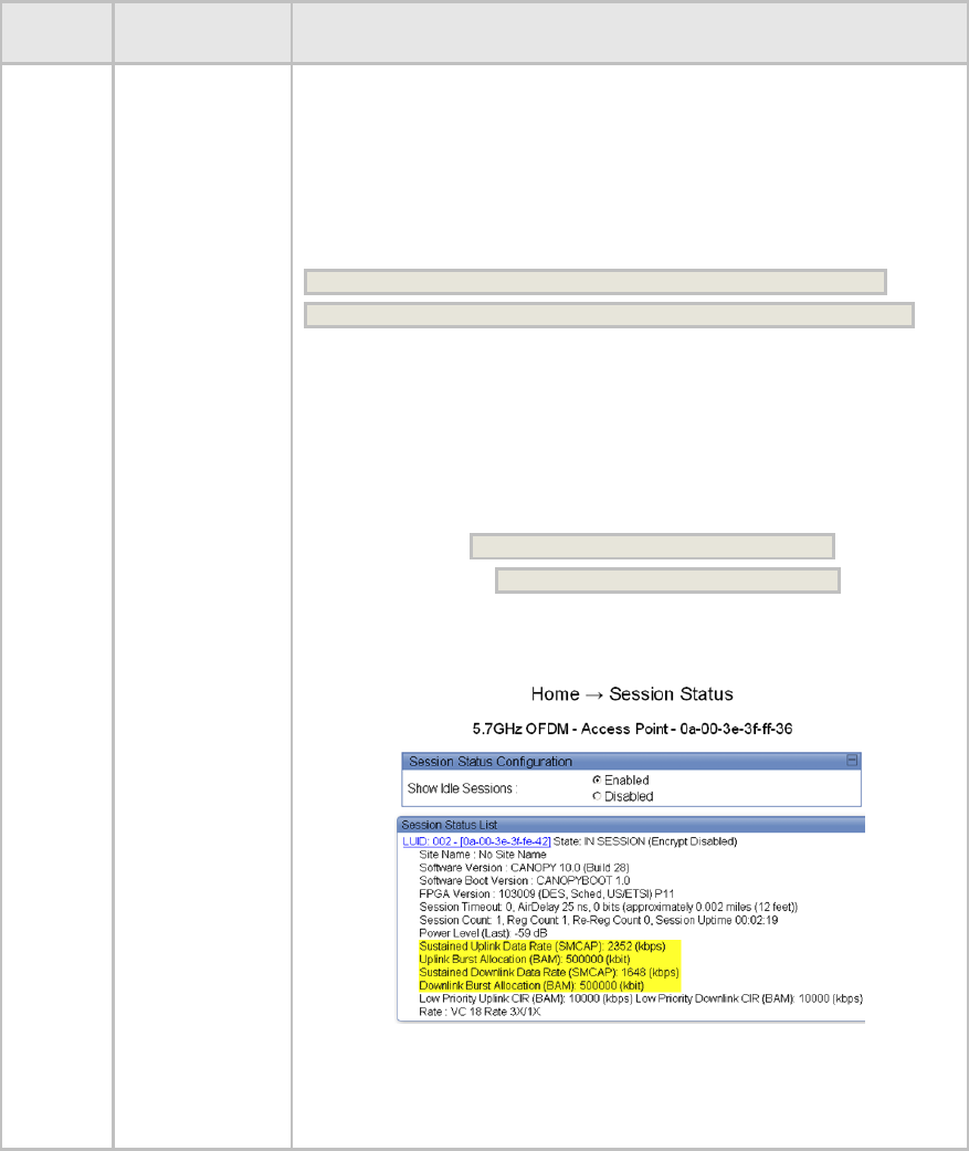
For example, if a PMP 430 4 Mbps SM with a max MIR cap of 4000
receives a MIR setting from Prizm that is greater than 4000 kbps, it will
cap the downlink MIR and the uplink MIR to equal a max of 4000 kbps.
Below is an example with Prizm settings of 10000 kbps uplink MIR and
7000 downlink MIR sent to a 4 Mbps SM that is capped at 4000 kbps max
MIR:
Uplink calculation: (10000 * 4000) / (7000 + 10000) = 2352 kbps
Downlink calculation: (7000 *4000) / (7000 + 10000) = 1648 kbps
Thus the Uplink MIR of 2352 + Downlink MIR of 1648 = 4000 kbps
In this example, the PMP 430 AP sessions page will display a SM uplink
and downlink MIR SMCAP as shown below.
For reference, the max SM MIR in kbps for each SM type is:
4 Mbps SM = 4000
10 Mbps SM = 10000
20 Mbps SM = 20000
40 Mbps SM = 65535 (displays Unlimited in the Home > General Status tab)

Release 10.5 Release Notes and User Guide Supplement
FCC Draft, November 2010 Page 19
Table 6: Notes first discussed with Release 9.5
Products
Affected
Description
Discussion and Recommendations
All
SM – DNS below
a NATed SM
when DNS Server
Proxy is enabled
Microsoft Vista and Windows 7 will not route a 169.254/16 subnet used as
the default Canopy subnet since these operating systems use 169.254/16
subnet to talk between local machines. This is not an issue if:
- the PC is connected directly to the NATed SM.
- the NAT/routing CPE underneath the NATed SM provides DNS services.
However; if a NAT/routing CPE that is not providing DNS services (e.g.
some home routers) is placed between the SM and the user’s PC, a
Microsoft Vista or Windows 7 machine will not route to the default
169.254/16 SM IP address space to access DNS services.
Workaround: Reconfigure the SMs NAT LAN address to a private IP
address such as 192.168/16, 172.16/12, or 10/8 or leave DNS Server
Proxy disabled.
All
Updating
Community
Strings on the
Web GUI (11699)
To flip-flop the read/write and read-only community string names, it is
necessary to change one community string to a temp name first before
switching community string names.
Remote
AP
Remote AP Sync
Input (7427)
Remote AP receives sync from SM by setting SYNC Input to Timing Port.
However, if this is incorrectly configured as SYNC input to Power port the
Remote AP will still correctly receive SYNC.
AP
Disable TCP ACK
prioritizing in
broadcast video
applications
(10263)
When optimizing a system for broadcast video, on the AP’s Configuration
=> General page configure Prioritized TCP ACK to Disabled.
In a system being used for internet access or similar applications
prioritizing TCP ACKs improves downloading of FTP files and other
activities making significant use of TCP ACKs under heavy load. However,
in a system being used for broadcast video or video surveillance,
prioritizing TCP ACKs can cause sporadic choppy video in the uplink.
AP or SM
Procedures for
saving an XML
file of a spectrum
graph (8484)
When the SpectrumAnalysis.xml button is clicked on the SM’s Tools >
Spectrum Analyzer tab or the AP’s Tools > Remote Spectrum Analyzer
tab, the spectrum graph is redisplayed using XML and XSL if the browser
supports XSL. To save the underlying XML file, right click and select “Save
Target As” on a Windows PC, or equivalent action for other operating
systems.
SM
SM scan
frequencies not
“cancelled” by
SNMP actions
(8172)
If you make frequency changes on the SM GUI, and then back them out
using SNMP, the Reboot Required message remains on the GUI.
Workaround:
If it says Reboot Required, go ahead and reboot, just to clear the
message.

Release 10.5 Release Notes and User Guide Supplement
FCC Draft, November 2010 Page 20
Products
Affected
Description
Discussion and Recommendations
All
Managing module
accounts and
passwords (none)
The best security practice is to be aware a factory unit comes with root
and admin accounts, to plan your approach to accounts, and set
passwords for all accounts.
A module that either is fresh from the factory or has been operator-reset to
factory defaults has two user accounts: root and admin, both with
ADMINISTRATOR level permissions.
To secure a module, access the Account => Change Users Password tab
and add a password to each of these accounts. Adding a password to only
one account still leaves the other open. Furthermore, an account without a
password will accept any password potentially giving the impression the
unit is protected when it isn’t.
Alternatively, an operator’s practices may be to delete the admin account
or delete the root account and replace them with their own account(s). By
default, Prizm, One Point Wireless Manager and CNUT use the root
account to manage the module, so if you delete root accounts on
modules you will need to make coordinated changes to Prizm, Wireless
Manager, and CNUT to access them with your own accounts.
All
Use 16 or fewer
alphanumeric
characters in user
account names,
passwords, and
Community
Strings (7808)
SNMP doesn’t do data-entry checking, so more than 16 characters may be
entered, but only 16 characters will be saved and displayed.
AP and
SM
Timed Spectrum
Analyzer settings
anomaly (7442)
Values of Timed Spectrum Analyzer duration and Spectrum Analysis
on Boot get saved by clicking any button on the page, not just when
clicking Save Changes or Start Time Spectrum Analysis (which is
typical operation for other pages).
AP and
SM
Best Practice is to
set SM to same
Region Code as
AP (none)
When an SM registers to an AP, it assumes the Region Code and
associated parameters of the AP, disregarding any Region code set in the
SM by you. However, the best practice is still for you to set a Region Code
in the SM so that displayed options are consistent with the region.
All
Details on pinging
Canopy modules
(4831)
A ping size larger than 1494 bytes to a radio will time out and fail.
However, a ping of greater than 1494 bytes to a system that is behind a
radio typically succeeds. To gain an accurate view of latency, ping through
the radio to a system beyond. Canopy transports ping traffic with the same
priority as all transport traffic, but may handle a direct ping with lower
priority when running under load.
SM
AP may be listed
twice in SM’s AP
Evaluation tab
(5298)
To help during aiming, the SM’s Tools > AP Evaluation tab maintains AP
entries for 15 minutes. If the frequency of an AP is changed, for 15
minutes the AP is listed twice in the AP Evaluation tab, once with the
former frequency, and once with the new one.
AP and
SM
When using Link
Test with MIR,
need to set both
ends (4844, 2756)
To see the effects of MIR capping, you can run a link test with MIR
enabled. To get meaningful results, set Link Test with MIR to Enabled on
the Tools => Link Capacity Test tab in both the SM and the AP. When it is
enabled on only one end, results are misleading.
After you run perform a link test with MIR capping enabled, consider
immediately changing Link Test with MIR to Disabled in both the SM and
the AP, to avoid mistakenly capping only one end of the link test.
Release 10.5 Release Notes and User Guide Supplement
FCC Draft, November 2010 Page 21
Products
Affected
Description
Discussion and Recommendations
AP and
SM
Click Spectrum
Analyzer Enable
button twice
(5284)
After you click the Enable button in the Tools => Spectrum Analyzer tab,
the resulting display may omit bars for some frequencies, especially in
frequency bands that have a large number of center channels, such as
the 5.4-GHz band. If you clicking Enable again, the display includes the
entire spectrum bar graph.
TIP: In the Configuration => General tab, set the Webpage Auto Update
parameter to a few seconds, to have the Spectrum Analyzer automatically
fully displayed and refreshed. You can later reset the Webpage Auto
Update time back to 0, to disable refresh.
AP and
SM
Blank screen after
logging in to SM
through AP
Session Status
tab (4706)
In some instances, depending on network activity and network design, the
interface presents a blank screen to a user who logs in to an SM through
the Home => Session Status tab in the AP. If you observe this, refresh
your browser window.
SM
When connecting
to a hub, use only
half duplex
Ethernet settings
(7557)
Ethernet connections set to 10 Base T Full Duplex or
100 Base T Full Duplex will not connect to an SM through a hub, due to
the way a hub works. Use half duplex settings when using a hub.
7.2 US REGION CODE OPERATION
A 5-GHz PMP 100/400/430 Series AP or a PTP 100/200 Series BH with a Region Code set to
United States is not configurable to another Region Code by installers or end users. This is in
response to FCC KDB 594280 and ensures that end users and professional installers do not
have access to settings which could allow a radio to be configured to operate in a manner other
than that which was specified in the FCC equipment authorization grant.
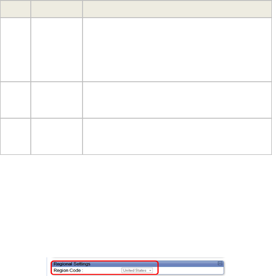
Radios sold in the United States and its territories come with the Region Code on the
Configuration > General tab pre-configured to United States and not selectable, as shown in
Figure 2. Radios sold in regions outside of the United States and its territories are required to be
set by the operator to the Region Code of the region in which they are used.
Figure 2: PMP AP and PTP BH Region Code Set to United States
7.3 PMP 430 CENTER CHANNELS
When the PMP 430 AP is using 5-MHz channels, the center channels can be configured every
2.5 MHz. When it is using 10- or 20-MHz channels, the center channels can be configured every
5 MHz. Available center channels as a function of channel size and regioin are shown in Table 7.
Note: PMP430 5.4-GHz for US does not include a 5-MHz channel size.

Release 10.5 Release Notes and User Guide Supplement
FCC Draft, November 2010 Page 22
Table 7: PMP 430 center channels by channel bandwidth and region code
OFDM
Radio
Model
Channel
Size
Region Code(s)
Range of Center
Frequencies
Available (MHz)
Center
Channel
Spacing
# of Center
Channels
Australia
5475 – 5597.5
5652.5 – 5715
2.5 MHz
76
Europe & Spain
5472.5 – 5597.5
5652.5 – 5717.5
2.5 MHz
78
5 MHz
Brazil, India, Russia & Other
5475 –5715
2.5 MHz
97
United States, Canada &
Australia
5480 – 5595
5655 – 5710
5 MHz
36
Europe & Spain
5475 – 5595
5655 – 5715
5 MHz
38
10 MHz
Brazil, India, Russia & Other
5480 – 5710
5 MHz
47
United States, Canada &
Australia
5480 – 5590
5660 – 5710
5 MHz
34
Europe & Spain
5475 – 5590
5660 – 5715
5 MHz
36
PMP 430
Series AP,
5.4-GHz
20 MHz
Brazil, India, Russia & Other
5480 – 5710
5 MHz
47
United States, Canada,
Australia, Brazil & Russia
5727.5 –5845
2.5 MHz
48
Europe & Other
5727.5 –5872.5
2.5 MHz
59
Spain
5727.5 – 5792.5
5817.5 – 5852.5
2.5 MHz
42
5 MHz
India
5827.5 –5872.5
2.5 MHz
19
United States, Canada,
Australia, Brazil & Russia
5730 – 5845
5 MHz
24
Europe & Other
5730 – 5870
5 MHz
29
Spain
5730 – 5790
5820 – 5850
5 MHz
20
10 MHz
India
5830 – 5870
5 MHz
9
United States, Canada,
Australia, Brazil & Russia
5735 – 5840
5 MHz
22
Europe & Other
5735 – 5865
5 MHz
27
Spain
5735 – 5785
5825 – 5845
5 MHz
16
PMP 430
Series AP,
5.8-GHz
20 MHz
India
5835 – 5865
5 MHz
7

Release 10.5 Release Notes and User Guide Supplement
FCC Draft, November 2010 Page 23
7.4 PMP 100 SERIES DFS OPERATION BASED ON REGION CODE
For reference, Table 8 shows operating based on Region Code, by frequency band and module
type. Note: 900MHz and 2.4-GHz are not shown as DFS operation does not apply to these frequencies.
Table 8: PMP 100 (FSK) AP/SM DFS operation based on region code
5.1
GHz
5.2 GHz
5.4 GHz
5.7 GHz
Region
Code1
AP/
SM
AP
SM
AP
SM
AP
SM
United
States
NA
≥P10:
FCC/IC
DFS
≤ P9:
no DFS
No
effect
FCC/IC DFS
No 5590-5660 MHz2
P11: Limited to 75%
Downlink Data
No
effect
No
effect
No
effect
Canada
NA
≥ P10:
FCC/IC
DFS
≤ P9:
no DFS
No
effect
FCC/IC DFS
No 5590-5660 MHz2
No
effect
No
effect
No
effect
Europe
&
Spain
NA
NA
NA
ETSI EN 301 893
v1.3.1 DFS
>July 1, 20083:
No 5590-5660 MHz2
ETSI EN 301
893 v1.3.1
DFS
>July 1, 20083:
No 5585-5665
MHz2
ETSI
EN 302
502
v1.2.1
DFS
ETSI EN
302 502
v1.2.1
DFS
Brazil
NA
NA
NA
P11: ETSI v1.4.1
DFS
≤ P10: ETSI v1.3.1
DFS
No
effect
No
effect
No
effect
Australia
NA
NA
NA
FCC/IC DFS
No 5590-5660 MHz2
No
effect
No
effect
No
effect
Russia
Display
Com-
munity
options
No
effect
No
effect
NA
NA
No
effect
No
effect
India or
Other
No
effect
No
effect
No
effect
No
effect
No
effect
No
effect
No
effect
1. Product sold in the US is locked to the US Region Code and has “US” in the model number. In
other cases, set the Region Code to the region you are in, and the software will determine the
correct use of DFS. For countries or regions not listed, use a Region Code that provides DFS
functionality and channels consistent with your country’s regulatory requirements.
2. Terminal Doppler Weather Radar (TDWR) operates on frequencies 5600 through 5650 MHz. In
some countries a “weather notch” is required to avoid impinging on these frequencies.
3. Radios placed on market in Europe after July 1, 2008, can’t impinge on weather radar frequencies.
To meet this requirement, the software checks the date code of the module and implements the
weather notch accordingly. You can tell if a 5.4-GHz module is “newer” or “older” by setting the
Region Code to Europe – if the notch frequencies are not shown on the Configuration => Radio
page, then the module is “newer”, if the notch frequencies are shown, the module is “older”.

Release 10.5 Release Notes and User Guide Supplement
FCC Draft, November 2010 Page 24
7.5 PTP 100 SERIES DFS OPERATION BASED ON REGION CODE
For reference, Table 9 shows operating based on Region Code, by frequency band and module
type.
Table 9: PTP 100 (FSK) BHM/BHS operation based on region code
2.4
GHz
5.1
GHz
5.2 GHz
5.4 GHz
5.7 GHz
Region
Code1
BH
BH
BHM
BHS
BHM
BHS
BHM
BHS
United
States
No
effect
NA
≥P10:
FCC/IC
DFS
≤ P9:
no DFS
No
effect
FCC/IC DFS
No 5590-5660
MHz2
P11: Limited to
75% Downlink
Data
No
effect
No
effect
No
effect
Canada
No
effect
NA
≥ P10:
FCC/IC
DFS
≤ P9:
no DFS
No
effect
FCC/IC DFS
No 5590-5660
MHz in FSK2
No
effect
No
effect
No
effect
Europe
No
effect
NA
NA
NA
ETSI EN
301 893
v1.3.1 DFS
>July 1, 083:
No 5590-
5660 MHz in
FSK2
ETSI EN
301 893
v1.3.1 DFS
>July 1, 083:
No 5585-
5665 MHz in
FSK2
ETSI
EN 302
502
v1.2.1
DFS
ETSI
EN 302
502
v1.2.1
DFS
Brazil
NA
NA
NA
NA
P11: ETSI
v1.4.1 DFS
≤ P10: ETSI
v1.3.1 DFS
No
effect
No
effect
No
effect
Australia
No
effect
NA
NA
NA
FCC/IC DFS
No 5590-5660
MHz in FSK2
No
effect
No
effect
No
effect
Russia
NA
Display
Com-
munity
options
No
effect
No
effect
NA
NA
No
effect
No
effect
India or
Other
No
effect
No
effect
No
effect
No
effect
No
effect
No
effect
No
effect
No
effect
1. Product sold in the US is locked to the US Region Code and has “US” in the model number. In other
cases, set the Region Code to the region you are in, and the software will determine the correct use of
DFS. For countries or regions not listed, use a Region Code that provides DFS functionality and
channels consistent with your country’s regulatory requirements.
2. Terminal Doppler Weather Radar (TDWR) operates on frequencies 5600 through 5650 MHz. In some
countries a “weather notch” is required to avoid impinging on these frequencies.
3. Radios placed on market in Europe after July 1, 2008, can’t impinge on weather radar frequencies. To
meet this requirement, the software checks the date code of the module and implements the weather
notch accordingly. You can tell if a 5.4-GHz module is “newer” or “older” by setting the Region Code to
Europe – if the notch frequencies are not shown on the Configuration => Radio page, then the module
is “newer”, if the notch frequencies are shown, the module is “older”.

Release 10.5 Release Notes and User Guide Supplement
FCC Draft, November 2010 Page 25
7.6 PMP 400/430 AND PTP 200 DFS OPERATION BASED ON REGION
CODE
For reference, Table 10 shows operation based on Region Code, by frequency band and radio
platform. PMP 400 and PTP 200 are available in the 5.4-GHz frequency band. PMP 430 is
available in both the 5.4 and 5.8-GHz frequency bands.
Note: The 4.9-GHz PMP 400 and PTP 200 are not shown as DFS operation does not apply to
these frequencies.
Table 10: PMP 400/430 and PTP 200 (OFDM) DFS operation based on region code
Region Code1
Frequency
Radio Platform
AP
SM
5.4-GHz
PMP 400/430 & PTP 200
FCC/IC DFS3
PMP 430
limited to 85%
Downlink Data,
no 5-MHz
channel size
No effect
United States
5.8-GHz
PMP 430
No effect
No effect
5.4-GHz
PMP 400/430 & PTP 200
FCC/IC DFS3
PMP 430 - no
5-MHz channel
size
No effect
Canada
5.8-GHz
PMP 430
No effect
No effect
5.4-GHz
PMP 400/430 & PTP 200
ETSI DFS4
ETSI DFS4
Europe &
Spain
5.8-GHz
PMP 430
ETSI DFS5
ETSI DFS5
5.4-GHz
PMP 400/430 & PTP 200
ETSI DFS4
No effect
Brazil
5.8-GHz
PMP 430
No effect
No effect
5.4-GHz
PMP 400/430 & PTP 200
FCC/IC DFS3
No effect
Australia
5.8-GHz
PMP 430
No effect
No effect
5.4-GHz
PMP 400/430 & PTP 200
No effect
No effect
Russia
5.8-GHz
PMP 430
No effect
No effect
5.4-GHz
PMP 400/430 & PTP 200
No effect
No effect
India
5.8-GHz
PMP 430
No effect
No effect
5.4-GHz
PMP 400/430 & PTP 200
No effect
No effect
Other
5.8-GHz
PMP 430
No effect
No effect
1. Product sold in the US is locked to the US Region Code and has “US” in the model number.
In other cases, set the Region Code to the region you are in, and the software will determine
the correct use of DFS. For countries or regions not listed, use a Region Code that provides
DFS functionality and channels consistent with your country’s regulatory requirements.
2. In some countries and regions, 5600 MHz to 5650 MHz is “notched” out to meet
requirements to not transmit in weather radar frequencies.
3. Complies with FCC Report and Order 03-287 and Industry Canada requirements.
4. Complies with ETSI EN 301 893 v1.3.1.
5. Complies with ETSI EN 302 502 v1.2.1.

Release 10.5 Release Notes and User Guide Supplement
FCC Draft, November 2010 Page 26
8 Canopy MIB
The Canopy Enterprise MIB (Management Information Base) consists of 5 MIB definition files and
supports SNMP access to Canopy modules. The MIB files are available for download from the
Canopy tab of http://motorola.wirelessbroadbandsupport.com/software.
Detailed information on the Canopy MIBs is available at
http://motorola.wirelessbroadbandsupport.com/support/online_tools.
MIB files are used by Network Management Systems and Element Management Systems, such
as the Motorola Prizm and One Point Wireless Manager systems, to support a host of
surveillance, monitoring, control, and operational tasks.
Information on the Motorola Prizm element management system is available at
http://www.motorola.com/Business/US-
EN/Business+Product+and+Services/Wireless+Broadband+Networks/Point-to-
Multipoint+Networks/Unlicensed+Point-to-
Multipoint+Solutions/Element_Management_PTMP_US-EN
Information on the Motorola One Point Wireless Manager management system is available at
http://www.onepointwireless.com/wirelessmanager/
Prizm and One Point Wireless Manager documentation and installers are available for download
from the Canopy tab of http://motorola.wirelessbroadbandsupport.com/software.
If you are using Prizm: Prizm 3.3.10 includes the MIB information. You do not need to load MIB
files.
If you are using One Point Wireless Manager 2.2 or an SNMP network management system
(NMS) or element management system (EMS) other than Prizm: Load the MIBs per the
instructions for One Point Wireless Manager 2.2 or your NMS or EMS.
Important! When loading the Canopy MIB files
1. First load the standard MIB files.
2. Then load the Canopy MIB files.
Some NMSs are not sensitive to order, but some require a specific loading order to build a MIB
tree. Loading in the recommended order avoids any problems arising from loading sequence.
Release 10.5 Release Notes and User Guide Supplement
FCC Draft, November 2010 Page 27
9 Performance Benchmarking Process
This section describes the performance benchmarking process.
9.1 DEFINITIONS
The following terms are used where these release notes discuss packet processing:
Aggregate Throughput
Sum of uplink plus downlink traffic.
Offered Load
Test equipment generates a specified load to the Ethernet interface
of a module (SM or the AP). The specifications of the load include
both packet size and packet rate.
Carried Load
Test equipment measures the load delivered at the Ethernet interface
of a module. The load is calculated from packet size and number of
packets. As resources are exhausted at any point in the system,
packets may be dropped. The Carried Load equals the Offered Load
minus Dropped Packets.
Downlink/Uplink Load Ratio
The ratio of downlink Carried Load to uplink Carried Load.
NOTE: Do not confuse the Downlink/Uplink Load Ratio with the
Downlink Data configuration parameter. The Downlink/Uplink Load
Ratio is determined from the Carried Loads. The Downlink Data is
set by the operator and determines the split of downlink and uplink
slots in the air frame.
9.2 SYSTEM PERFORMANCE AND SYSTEM CONSTRAINTS
Different combinations of system inputs will result in different constraints limiting system
performance.
Larger Packets
With larger packets (the system handles packets up to 1522 Bytes), the system constraint is
airtime, which can also be stated as slots, or maximum bits per second.
This can be calculated as follows:
PMP 100 and PTP 100 Backhauls with 20MHz Channels:
64 Bytes/fragment x 2 fragments/slot x 34 slots/frame x 400 frames/sec x 8 bits/byte = 14 Mbps
This is an aggregate (uplink plus downlink) limit, as the Canopy system is a Time Division Duplex
(TDD) system.
14 Mbps is a typical maximum aggregate throughput for larger packet sizes for an FSK system.
Longer range settings can reduce the number of slots in a frame and packet size (breakage on
64-byte boundaries) can affect packing efficiency (the percentage of fragments fully packed with
64 bytes).
PMP 430 (5.4 and 5.8-GHz OFDM) with 5MHz Channels:
For 1/4 Cyclic Prefix the calculation is
64 Bytes/fragment x 3 fragments/slot x 15 slots/frame x 400 frames/sec x 8 bits/byte = 9.2 Mbps
Release 10.5 Release Notes and User Guide Supplement
FCC Draft, November 2010 Page 28
For 1/8 Cyclic Prefix the calculation is
64 Bytes/fragment x 3 fragments/slot x 17 slots/frame x 400 frames/sec x 8 bits/byte = 10.4 Mbps
For 1/16 Cyclic Prefix the calculation is
64 Bytes/fragment x 3 fragments/slot x 18 slots/frame x 400 frames/sec x 8 bits/byte = 11.0 Mbps
With 5MHz channels, 9.2 Mbps is a typical maximum aggregate (uplink plus downlink) throughput
for larger packet sizes in a system configured with 1/4 cyclic prefix. For 1/8 cyclic prefix systems
10.4 Mbps is a typical maximum aggregate throughput and for 1/16 cyclic prefix 11.0 Mbps is a
typical maximum aggregate throughput. Longer range settings can reduce the number of slots in
a frame and packet size (breakage on 64-byte boundaries) can affect packing efficiency (the
percentage of fragments fully packed with 64 bytes).
PMP 430 (5.4 and 5.8-GHz OFDM) with 10MHz Channels:
For 1/4 Cyclic Prefix the calculation is
64 Bytes/fragment x 3 fragments/slot x 33 slots/frame x 400 frames/sec x 8 bits/byte = 20.2 Mbps
For 1/8 Cyclic Prefix the calculation is
64 Bytes/fragment x 3 fragments/slot x 37 slots/frame x 400 frames/sec x 8 bits/byte = 22.7 Mbps
For 1/16 Cyclic Prefix the calculation is
64 Bytes/fragment x 3 fragments/slot x 42 slots/frame x 400 frames/sec x 8 bits/byte = 25.8 Mbps
With 10MHz channels, 20.2 Mbps is a typical maximum aggregate (uplink plus downlink)
throughput for larger packet sizes in a system configured with 1/4 cyclic prefix. For 1/8 cyclic
prefix systems 22.7 Mbps is a typical maximum aggregate throughput and for 1/16 cyclic prefix
25.8 Mbps is a typical maximum aggregate throughput. Longer range settings can reduce the
number of slots in a frame and packet size (breakage on 64-byte boundaries) can affect packing
efficiency (the percentage of fragments fully packed with 64 bytes).
PMP 430 (5.4 and 5.8-GHz OFDM) with 20MHz Channels:
For 1/4 Cyclic Prefix the calculation is
64 Bytes/fragment x 3 fragments/slot x 73 slots/frame x 400 frames/sec x 8 bits/byte = 44.8 Mbps
For 1/8 Cyclic Prefix the calculation is
64 Bytes/fragment x 3 fragments/slot x 81 slots/frame x 400 frames/sec x 8 bits/byte = 49.7 Mbps
For 1/16 Cyclic Prefix the calculation is
64 Bytes/fragment x 3 fragments/slot x 86 slots/frame x 400 frames/sec x 8 bits/byte = 52.8 Mbps
With 20MHz channels, 44.8 Mbps is a typical maximum aggregate (uplink plus downlink)
throughput for larger packet sizes in a system configured with 1/4 cyclic prefix. For 1/8 cyclic
prefix systems 49.7 Mbps is a typical maximum aggregate throughput and for 1/16 cyclic prefix
52.8 Mbps is a typical maximum aggregate throughput. Longer range settings can reduce the
number of slots in a frame and packet size (breakage on 64-byte boundaries) can affect packing
efficiency (the percentage of fragments fully packed with 64 bytes).
Smaller Packets
With smaller packets, the system constraint is processing power in any module handling the
traffic stream. Even though there may be airtime or slots available, the overall throughput is
limited by packet handling ability.
Release 10.5 Release Notes and User Guide Supplement
FCC Draft, November 2010 Page 29
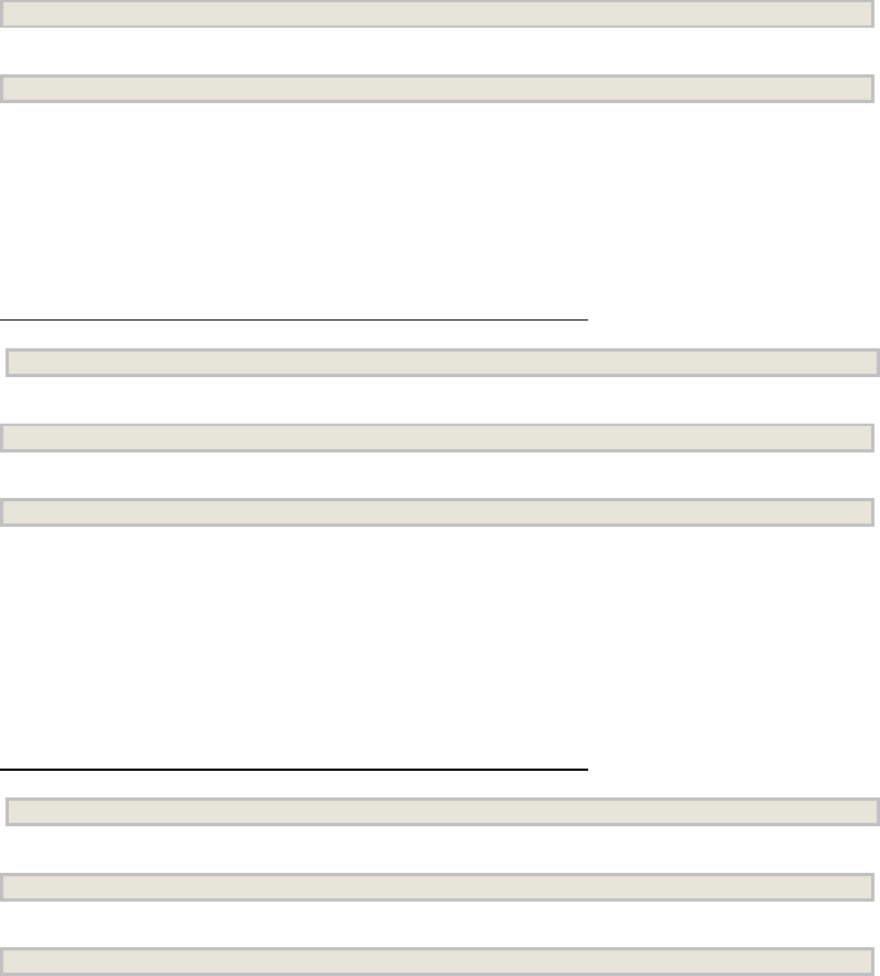
9.3 BENCHMARK DEFINITION
In a complex system, any measurement depends on system configuration, traffic mix, various
settings, and measurement techniques, and so to have reproducible results a “benchmark” is
defined.
System configuration
The PMP benchmark system consists of 3 SMs and 1 Advantage AP, as shown in Figure 3 on
page 30. Traffic generation and measurement equipment is connected to both SMs and the AP.
Traffic is generated such that any one packet attempts to traverse an SM and then the AP, or the
AP and then an SM. No SM-to-SM traffic is included in the benchmark. RF conditions are
maintained such that all links run at max rate (2X or 3X).
Traffic mix/Packet size
All generated packets have a size of 64 Bytes. The packet format used is a valid Ethernet/IP
packet. The performance of interest is performance near a 50% Downlink/Uplink Load Ratio.
PMP Settings
Downlink Data: 50%
Control Slots: 2
Range: 2 miles
Max rate (2X or 3X) Enabled
Encryption: Enabled (DES modules)
MIR: 20,000 kbits/sec sustained rate and 500,000 kbits burst allocation
(defaults)
CIR: 0 (default)
NAT: Disabled (default)
VLAN: Disabled (default)
High Priority: Disabled (default)
PTP Settings
Downlink Data: 50%
Max rate (2X or 3X) Enabled
Encryption: Enabled (DES modules)
Measurement technique
1. Send a specific number of frames at a specific rate through SMs and AP (uplinks) and AP
and SM (downlink) simultaneously. This is the Offered Load. Count the frames that are
received correctly at both sides. This is the Carried Load. Repeat this through the load
rates of interest. Review the results, noting where the packet loss (the difference between
the Offered Load and Carried Load) is essentially zero (<0.001%).
2. Confirm results by running longer tests at selected load rates.
3. Confirm results by varying Downlink/Uplink Load Ratios to ensure no significant changes
around the 50% benchmark.
Release 10.5 Release Notes and User Guide Supplement
FCC Draft, November 2010 Page 30
SM2 AP
SM3
Ixia Test Controller
and Load Modules
All packets 64 Bytes
x/2 pps
x/2 pps
x/6 pps
x/6 pps
x/6 pps
x/6 pps
x/6 pps
x/6 pps
x pps
SM1
Figure 3: PPS Benchmark Test Setup
Release 10.5 Release Notes and User Guide Supplement
FCC Draft, November 2010 Page 31
10 Regulatory and Legal Notices
10.1 IMPORTANT NOTE ON MODIFICATIONS
Intentional or unintentional changes or modifications to the equipment must not be made unless under the
express consent of the party responsible for compliance. Any such modifications could void the user’s
authority to operate the equipment and will void the manufacturer’s warranty.
10.2 NATIONAL AND REGIONAL REGULATORY NOTICES
10.2.1 U.S. Federal Communication Commission (FCC) Notification
For 900MHz, 2.4, 5.2, 5.4, 5.7 and 5.8-GHz devices:
This device complies with Part 15 of the US FCC Rules and Regulations. Operation is subject to the
following two conditions: (1) This device may not cause harmful interference, and (2) This device must
accept any interference received, including interference that may cause undesired operation.
This equipment has been tested and found to comply with the limits for a Class B digital device, pursuant to
Part 15 of the US FCC Rules. These limits are designed to provide reasonable protection against harmful
interference in a residential installation. This equipment generates, uses, and can radiate radio-frequency
energy and, if not installed and used in accordance with these instructions, may cause harmful interference
to radio communications. If this equipment does cause harmful interference to radio or television
reception, which can be determined by turning the equipment on and off, the user is encouraged to correct
the interference by one or more of the following measures:
Increase the separation between the affected equipment and the unit;
Connect the affected equipment to a power outlet on a different circuit from that which
the receiver is connected to;
Consult the dealer and/or experienced radio/TV technician for help.
FCC IDs and the specific configurations covered are listed in Table 11.
Specific instructions to avoid interfering with Terminal Doppler Weather Radar (TDWR) are included below
Table 11.
For 4.9-GHz devices:
The 4.9-GHz band is a licensed band allocated to public safety services. State and local government entities
that provide public safety services are eligible to apply for 4.9 GHz licenses. For additional information, refer
to FCC regulations.

Release 10.5 Release Notes and User Guide Supplement
FCC Draft, November 2010 Page 32
Table 11: US FCC IDs and Industry Canada Certification Numbers and covered configurations
FCC ID
Industry
Canada
Cert
Number
Frequencies and Channels
Module
Families
Antenna
Maximum
Tx
Output
Power
12 dBi integrated
antenna
24 dBm
(250 mW)
17 dBi Last Mile Gear
Cyclone 900-17H Yagi
18 dBm
(63 mW)
10 dBi Maxrad Model #
Z1681 (MP9027XFPT
or Motorola AN900A)
flat panel
26 dBm
(390 mW)
10 dBi Mars Model #
MA-IS91-T2, flat panel
26 dBm
(390 mW)
ABZ89FC5809
109W-9000
8 MHz channels, centered on
906-924 MHz in 1 MHz
increments (within the 902-
928 MHz ISM band)
9000 SM, AP
(PMP 100)
10 dBi MTI Model #
MT-2630003/N (MT-
263003/N) flat panel
26 dBm
(390 mW)
2400 BH, SM,
AP
8 dBi internal
25 dBm
(340 mW)
ABZ89FC5808
109W-2400
20 MHz channels, centered on
2415-2457.5 MHz in 2.5 MHz
increments (within the 2400-
2483.5 MHz ISM band)
2400 BH, SM
8 dBi internal +
11 dB reflector
25 dBm
(340 mW)
7 dBi internal
23 dBm
(200 mW)
7 dBi internal +
18 dB reflector
5 dBm
(3.2 mW)
ABZ89FC3789
109W-5200
20 MHz channels, centered on
5275-5325 MHz in 5 MHz
increments (within the 5250-
5350 MHz U-NII band)
5200 BH, SM,
AP
(PMP 100,
PTP 100)
7 dBi internal +
9 dB lens
14 dBm
(25 mW)
7 dBi internal
23 dBm
(200 mW)
7 dBi internal +
18 dB reflector
5 dBm
(3.2 mW)
ABZ89FT7623
109W-5400
20 MHz channels, centered on
5495-5585 and 5665-5705
MHz in 5 MHz increments
(within the 5470-5725 MHz U-
NII band with 5600-5650 MHz
excluded)
5400 BH, SM,
AP
(PMP 100,
PTP 100)
7 dBi internal +
9 dB lens
14 dBm
(25 mW)
5700 BH, SM,
AP
7 dBi internal
23 dBm
(200 mW)
7 dBi internal +
18 dB reflector
23 dBm
(200 mW)
5700 BH, SM
(PMP 100,
PTP 100)
7 dBi internal +
10 dB lens
23 dBm
(200 mW)
ABZ89FC5804
109W-5700
20 MHz channels, centered on
5735-5840 MHz in 5 MHz
increments (within the 5725-
5850 MHz ISM band)
5700 AP
(PMP 100)
7 dBi internal +
10 dB lens
19 dBm
(80 mW)

Release 10.5 Release Notes and User Guide Supplement
FCC Draft, November 2010 Page 33
FCC ID
Industry
Canada
Cert
Number
Frequencies and Channels
Module
Families
Antenna
Maximum
Tx
Output
Power
5 MHz channels, centered on
5727.5-5845 in 5 MHz
increments (within the 5725-
5850 MHz ISM band)
19 dBm
10 MHz channels, centered on
5730-5845 in 5 MHz
increments (within the 5725-
5850 MHz ISM band)
19 dBm
ABZ89FT7634
109W-5780
20 MHz channels, centered on
5735-5840 in 5 MHz
increments (within the 5725-
5850 MHz ISM band)
5780 APC
(PMP 430)
17 dBi connectorized
PCTEL Model
8514724E01 antenna
(60° x 5° -3 dB beam
width) with 1 dB
connector cable loss
19 dBm
5 MHz channels, centered on
5727.5-5845 in 5 MHz
increments (within the 5725-
5850 MHz ISM band)
19 dBm
10 MHz channels, centered on
5730-5845 in 5 MHz
increments (within the 5725-
5850 MHz ISM band)
19 dBm
ABZ89FT7635
109W-5790
20 MHz channels, centered on
5735-5840 in 5 MHz
increments (within the 5725-
5850 MHz ISM band)
5790 SM
(PMP 430)
10 dBi (55° x 55° -3 dB
beam width)
19 dBm
10 MHz channels, centered on
5480-5595 and 5655-5710
MHz in 5 MHz increments
(within the 5470-5725 MHz U-
NII band with 5600-5650 MHz
excluded)
10 dBm
ABZ89FT7637
109W-5480
20 MHz channels, centered on
5485-5590 and 5660-5705
MHz in 5 MHz increments
(within the 5470-5725 MHz U-
NII band with 5600-5650 MHz
excluded)
5480 APC
(PMP 430)
18 dBi connectorized
PCTEL Model
8514724E01 antenna
(60° x 5° -3 dB beam
width) with 1 dB
connector cable loss
13 dBm
10 MHz channels, centered on
5480-5595 and 5655-5710
MHz in 5 MHz increments
(within the 5470-5725 MHz U-
NII band with 5600-5650 MHz
excluded)
17 dBm
ABZ89FT7638
109W-5490
20 MHz channels, centered on
5485-5590 and 5660-5705
MHz in 5 MHz increments
(within the 5470-5725 MHz U-
NII band with 5600-5650 MHz
excluded)
5490 SM
(PMP 430)
10 dBi (55° x 55° -3 dB
beam width)
19 dBm

Release 10.5 Release Notes and User Guide Supplement
FCC Draft, November 2010 Page 34
FCC ID
Industry
Canada
Cert
Number
Frequencies and Channels
Module
Families
Antenna
Maximum
Tx
Output
Power
5440 AP
(PMP 400)
18 dBi connectorized
PCTEL Model
8514724E01 antenna
(60° x 5° -3 dB beam
width) with 1 dB
connector cable loss
10 dBm
ABZ89FT7629
109W-5440
10 MHz channels, centered on
5480-5595 and 5655-5710
MHz in 5 MHz increments
(within the 5470-5725 MHz U-
NII band with 5600-5650 MHz
excluded)
5440 SM
(PMP 400)
5440 BH
(PTP 200)
17 dBi integrated
antenna (15° x 15° -3
dB beam width)
10 dBm
4940 AP
(PMP 400)
18 dBi connectorized
PCTEL Model AP
85010066001 antenna
(60° x 5° -3 dB beam
width) with 1 dB cable
loss
18 dBm
ABZ89FT7631
109W-4940
10 MHz channels, centered on
4945-4985 in 5 MHz
increments (within the 4940-
4990 MHz public safety
licensed band)
4940 SM
(PMP 400)
4940 BH
(PTP 200)
17 dBi integrated
antenna (15.5° x 17.5°
(el x az) -3 dB beam
width)
18 dBm
To ensure regulatory compliance, including DFS compliance, the professional installer is responsible for:
◦ setting the Transmitter Output Power on the Confiiguration => Radio page no higher than listed for a given
configuration
◦ setting the External Gain on the Configuration => Radio page, if displayed, to the gain of any external device
(such as a reflector or lens)
◦ following instructions to avoid interfering with Terminal Doppler Weather Radar (TDWR) in the 5470-5725
MHz U-NII band.
10.2.2 Industry Canada (IC) Notification
For 900MHz, 2.4-GHz, 5.2-GHz. 5.4-GHz, 5.7-GHz and 5.8-GHz devices:
This device complies with RSS-210 of Industry Canada. Operation is subject to the following two conditions:
(1) This device may not cause harmful interference, and (2) This device must accept any interference
received, including interference that may cause undesired operation.
Users should be cautioned to take note that in Canada high power radars are allocated as primary users
(meaning they have priority) of 5250 – 5350 MHz and 5650 – 5850 MHz and these radars could cause
interference and/or damage to license-exempt local area networks (LELAN).
This equipment has been tested and found to comply with the limits for a Class B digital device, pursuant to
RSS-210 of Industry Canada. These limits are designed to provide reasonable protection against harmful
interference in a residential installation. This equipment generates, uses, and can radiate radio-frequency
energy and, if not installed and used in accordance with these instructions, may cause harmful interference
to radio communications. If this equipment does cause harmful interference to radio or television
reception, which can be determined by turning the equipment on and off, the user is encouraged to correct
the interference by one or more of the following measures:
Increase the separation between the affected equipment and the unit;

Release 10.5 Release Notes and User Guide Supplement
FCC Draft, November 2010 Page 35
Connect the affected equipment to a power outlet on a different circuit from that which
the receiver is connected to;
Consult the dealer and/or experienced radio/TV technician for help.
To reduce potential radio interference to other users, the antenna type and its gain should be chosen so its
Equivalent Isotropic Radiated Power (EIRP) is not more than that permitted for successful communication.
Industry Canada Certification Numbers and the specific configurations covered are listed in Table 11.
This device has been designed to operate with the antennas listed in Table 11 and having a maximum gain
as shown in Table 11. Antennas not included or having a gain greater than as shown in Table 11 are strictly
prohibited from use with this device. Required antenna impedance is 50 ohms.
For 4.9-GHz devices:
The 4.9-GHz band is a licensed band allocated to public safety services. Government entities that provide
public safety services are eligible to apply for 4.9 GHz licenses. For additional information, refer to Industry
Canada regulations.
10.2.3 Regulatory Requirement for CEPT Member States (www.cept.org)
When operated in accordance with the instructions for use, Motorola Canopy Wireless equipment operating
in the 2.4 and 5.4 GHz bands is compliant with CEPT Recommendation 70-03 Annex 3 for Wideband Data
Transmission and HIPERLANs. For compliant operation in the 2.4 GHz band, the transmit power (EIRP)
from the built-in patch antenna and any associated reflector dish shall be no more than 100mW (20dBm).
For compliant operation in the 5.4 GHz band, the transmit power (EIRP) from the built-in patch antenna and
any associated reflector dish shall be no more than 1 W (30 dBm).
The following countries have completely implemented CEPT Recommendation 70-03 Annex 3A (2.4 GHz
band):
EU & EFTA countries: Austria, Belgium, Denmark, Spain, Finland, Germany, Greece,
Iceland, Italy, Ireland, Liechtenstein, Luxembourg, Netherlands, Norway, Portugal,
Switzerland, Sweden, UK
New EU member states: Bulgaria, Czech Republic, Cyprus, Estonia, Hungary,
Lithuania, Latvia, Malta, Poland, Slovenia, Slovakia
Other non-EU & EFTA countries: Bosnia and Herzegovina, Turkey
The following countries have a limited implementation of CEPT Recommendation 70-03 Annex 3A:
France – Outdoor operation at 100mW is only permitted in the frequency band 2400
to 2454 MHz;
− Any outdoor operation in the band 2454 to 2483.5MHz shall not exceed 10mW (10dBm);
− Indoor operation at 100mW (20dBm) is permitted across the band 2400 to 2483.5 MHz
French Overseas Territories:
− Guadeloupe, Martinique, St Pierre et Miquelon, Mayotte – 100mW indoor & outdoor is allowed
− Réunion and Guyana – 100mW indoor, no operation outdoor in the band 2400 to 2420MHz
Italy – If used outside own premises, general authorization required
Luxembourg - General authorization required for public service
Romania – Individual license required. T/R 22-06 not implemented
Motorola Canopy Radios operating in the 2400 to 2483.5MHz band are categorized as “Class 2” devices
within the EU and are marked with the class identifier symbol , denoting that national restrictions apply
(for example, France). The French restriction in the 2.4 GHz band will be removed in 2011.
This 2.4 GHz equipment is “CE” marked to show compliance with the European Radio &
Telecommunications Terminal Equipment (R&TTE) directive 1999/5/EC. The relevant Declaration of
Conformity can be found at http://motorola.wirelessbroadbandsupport.com/doc.php.
Release 10.5 Release Notes and User Guide Supplement
FCC Draft, November 2010 Page 36
Where necessary, the end user is responsible for obtaining any National licenses required to operate this
product and these must be obtained before using the product in any particular country. However, for CEPT
member states, 2.4 GHz Wideband Data Transmission equipment has been designated exempt from
individual licensing under decision ERC/DEC(01)07. For EU member states, RLAN equipment in both the
2.4 & 5.4GHz bands is exempt from individual licensing under Commission Recommendation 2003/203/EC.
Contact the appropriate national administrations for details on the conditions of use for the bands in question
and any exceptions that might apply. Also see www.ero.dk for further information.
Motorola Canopy Radio equipment operating in the 5470 to 5725 MHz band are categorized as “Class 1”
devices within the EU in accordance with ECC DEC(04)08 and are “CE” marked to show compliance
with the European Radio & Telecommunications Terminal Equipment (R&TTE) directive 1999/5/EC. The
relevant Declaration of Conformity can be found at http://motorola.wirelessbroadbandsupport.com/doc.php.
A European Commission decision, implemented by Member States on 31 October 2005, makes the
frequency band 5470-5725 MHz available in all EU Member States for wireless access systems. Under this
decision, the designation of Canopy 5.4GHz products become “Class 1 devices” and these do not require
notification under article 6, section 4 of the R&TTE Directive. Consequently, these 5.4GHz products are only
marked with the symbol and may be used in any member state.
For further details, see
http://europa.eu.int/information_society/policy/radio_spectrum/ref_documents/index_en.htm
10.2.4 European Union Notification for 5.7 and 5.8 GHz Product
The 5.7 and 5.8 GHz connectorized product is a two-way radio transceiver suitable for use in Broadband
Wireless Access System (WAS), Radio Local Area Network (RLAN), or Fixed Wireless Access (FWA)
systems. It is a Class 2 device and uses operating frequencies that are not harmonized throughout the EU
member states. The operator is responsible for obtaining any national licenses required to operate this
product and these must be obtained before using the product in any particular country.
This equipment is marked to show compliance with the European R&TTE directive 1999/5/EC.
The relevant Declaration of Conformity can be found at
http://motorola.wirelessbroadbandsupport.com/doc.php.
10.2.5 Equipment Disposal
Waste (Disposal)
of Electronic
and Electric
Equipment
Please do not dispose of Electronic and Electric Equipment or Electronic and Electric Accessories with your
household waste. In some countries or regions, collection systems have been set up to handle waste of
electrical and electronic equipment. In European Union countries, please contact your local equipment
supplier representative or service center for information about the waste collection system in your country.
10.2.6 EU Declaration of Conformity for RoHS Compliance
Motorola hereby, declares that these Motorola products are in compliance with the essential requirements
and other relevant provisions of Directive 2002/95/EC, Restriction of the use of certain Hazardous
Substances (RoHS) in electrical and electronic equipment.
The relevant Declaration of Conformity can be found at
http://motorola.wirelessbroadbandsupport.com/doc.php.
10.2.7 UK Notification
The 5.7 and 5.8 GHz connectorized product has been notified for operation in the UK, and when operated in
accordance with instructions for use it is compliant with UK Interface Requirement IR2007. For UK use,
installations must conform to the requirements of IR2007 in terms of EIRP spectral density against elevation
Release 10.5 Release Notes and User Guide Supplement
FCC Draft, November 2010 Page 37
profile above the local horizon in order to protect Fixed Satellite Services. The frequency range 5795-5815
MHz is assigned to Road Transport & Traffic Telematics (RTTT) in the U.K. and shall not be used by FWA
systems in order to protect RTTT devices. UK licensing specifies that radiolocation services shall be
protected by a Dynamic Frequency Selection (DFS) mechanism to prevent co-channel operation in the
presence of radar signals.
10.2.8 Belgium Notification
Belgium national restrictions in the 2.4 GHz band include
EIRP must be lower then 100 mW
For crossing the public domain over a distance >300m the user must have the
authorization of the BIPT.
No duplex working
10.2.9 Luxembourg Notification
For the 2.4 GHz band, point-to-point or point-to-multipoint operation is only allowed on campus areas.
5.4GHz products can only be used for mobile services.
10.2.10Czech Republic Notification
2.4 GHz products can be operated in accordance with the Czech General License No. GL-12/R/2000.
5.4 GHz products can be operated in accordance with the Czech General License No. GL-30/R/2000.
10.2.11Norway Notification
Use of the frequency bands 5725-5795 / 5815-5850 MHz are authorized with maximum radiated power of 4
W EIRP and maximum spectral power density of 200 mW/MHz. The radio equipment shall implement
Dynamic Frequency Selection (DFS) as defined in Annex 1 of ITU-R Recommendation M.1652 / EN
301 893. Directional antennae with a gain up to 23 dBi may be used for fixed point-to-point links. The power
flux density at the border between Norway and neighboring states shall not exceed – 122.5 dBW/m2
measured with a reference bandwidth of 1 MHz.
Canopy 5.7 and 5.8 GHz connectorized products have been notified for use in Norway and are compliant
when configured to meet the above National requirements. Users shall ensure that DFS functionality is
enabled, maximum EIRP respected for a 20 MHz channel, and that channel spacings comply with the
allocated frequency band to protect Road Transport and Traffic Telematics services (for example, 5735,
5755, 5775 or 5835 MHz are suitable carrier frequencies). Note that for directional fixed links, TPC is not
required, conducted transmit power shall not exceed 30 dBm, and antenna gain is restricted to 23 dBi
(maximum of 40W from the Canopy 5.7 and 5.8 GHz connectorized products).
10.2.12Brazil Notification
Local regulations do not allow the use of 900 MHz, 2.4 GHz, or 5.2 GHz Canopy modules in Brazil.
For compliant operation of an AP in the 5.8 GHz band, the Equivalent Isotropic Radiated Power from the
built-in patch antenna and any associated reflector dish or LENS shall not exceed 36 dBm (4 W). When
using the passive reflector (18 dB), transmitter output power must be configured no higher than 11 dBm.
When using the LENS (10 dB at 5.8 GHz), transmitter output power must be configured no higher than 19
dBm.
For compliant operation in the 5.4 GHz band, the Equivalent Isotropic Radiated Power from the built-in patch
antenna and any associated reflector dish or LENS shall not exceed 30 dBm (1 W). When using the passive
reflector (18 dB), transmitter output power must be configured no higher than 5 dBm. When using the LENS
(9 dB at 5.4 GHz), transmitter output power must be configured no higher than 14 dBm. When not using the
passive reflector or the LENS, the transmitter output power of the radio must be configured no higher than
23 dBm.
The operator is responsible for enabling the DFS feature on any Canopy 5.4 GHz radio by setting the
Region Code to “Brazil”, including after the module is reset to factory defaults.
Release 10.5 Release Notes and User Guide Supplement
FCC Draft, November 2010 Page 38
Important Note: This equipment operates as a secondary application, so it has no rights against harmful
interference, even if generated by similar equipment, and cannot cause harmful interference on systems
operating as primary applications.
10.2.13Australia Notification
900 MHz modules must be set to transmit and receive only on center channels of 920, 922, or 923 MHz so
as to stay within the ACMA approved band of 915 MHz to 928 MHz for the class license and not interfere
with other approved users.
After taking into account antenna gain (in dBi), 900 MHz modules’ transmitter output power (in dBm) must
be set to stay within the legal regulatory limit of 30 dBm (1 W) EIRP for this 900 MHz frequency band.
10.2.14Labeling and Disclosure Table for China
The People’s Republic of China requires that Motorola’s products comply with China Management Methods
(CMM) environmental regulations. (China Management Methods refers to the regulation Management
Methods for Controlling Pollution by Electronic Information Products.) Two items are used to demonstrate
compliance; the label and the disclosure table.
The label is placed in a customer visible position on the product.
Logo 1 means that the product contains no substances in excess of the maximum
concentration value for materials identified in the China Management Methods
regulation.
Logo 2 means that the product may contain substances in excess of the maximum
concentration value for materials identified in the China Management Methods
regulation, and has an Environmental Friendly Use Period (EFUP) in years, fifty years
in the example shown.
Logo 1
Logo 2
The Environmental Friendly Use Period (EFUP) is the period (in years) during which the Toxic and
Hazardous Substances (T&HS) contained in the Electronic Information Product (EIP) will not leak or mutate
causing environmental pollution or bodily injury from the use of the EIP. The EFUP indicated by the Logo 2
label applies to a product and all its parts. Certain field-replaceable parts, such as battery modules, can
have a different EFUP and are marked separately.
The Disclosure table is intended to communicate compliance with only China requirements; it is not intended
to communicate compliance with EU RoHS or any other environmental requirements.
Table 12: China disclosure table
有毒有害物质或元素
部件名称
铅
(Pb)
汞
(Hg)
镉
(Cd)
六价铬
(Cr6+)
多溴联苯
(PBB)
多溴二苯醚
(PBDE)
金属部件
×
○
×
×
○
○
电路模块
×
○
×
×
○
○
电缆及电缆组件
×
○
×
×
○
○
Release 10.5 Release Notes and User Guide Supplement
FCC Draft, November 2010 Page 39
塑料和聚合物部件
○
○
○
○
○
×
○:
表示该有毒有害物质在该部件所有均质材料中的含量均在SJ/T11363-2006 标准规定的限量要求以下。
×:
表示该有毒有害物质至少在该部件的某一均质材料中的含量超出SJ/T11363-2006
标准规定的限量要求。
10.3 RF EXPOSURE SEPARATION DISTANCES
To protect from overexposure to RF energy, install Canopy radios so as to provide and maintain
the minimum separation distances from all persons shown in Table 13.
Table 13: Exposure separation distances
Module Type
Separation Distance from Persons
Canopy Module (FSK or OFDM)
At least 20 cm (approx 8 in)
Canopy Module with Reflector Dish
At least 1.5 m (approx 5 ft)
Canopy Module with LENS
At least 50 cm (approx 20 in)
900 MHz, integrated or connectorized antenna
At least 80 cm (32 in)
Indoor 900 MHz SM
At least 10 cm (4 in)
The following section and its Table 14 provide details and discussion of the associated
calculations.
10.3.1 Details of Exposure Separation Distances Calculations and Power
Compliance Margins
Limits and guidelines for RF exposure come from:
US FCC limits for the general population. See the FCC web site at
http://www.fcc.gov, and the policies, guidelines, and requirements in Part 1 of
Title 47 of the Code of Federal Regulations, as well as the guidelines and
suggestions for evaluating compliance in FCC OET Bulletin 65.
Health Canada limits for the general population. See the Health Canada web
site at http://www.hc-sc.gc.ca/rpb and Safety Code 6.
ICNIRP (International Commission on Non-Ionizing Radiation Protection)
guidelines for the general public. See the ICNIRP web site at
http://www.icnirp.de/ and Guidelines for Limiting Exposure to Time-Varying
Electric, Magnetic, and Electromagnetic Fields.
The applicable power density exposure limits from the documents referenced above are
10 W/m2 for RF energy in the 5.7/5.8-GHz frequency bands.
Peak power density in the far field of a radio frequency point source is calculated as follows:

Release 10.5 Release Notes and User Guide Supplement
FCC Draft, November 2010 Page 40
!
S=P"G
4
#
d2
where
S = power density in W/m2
P = RMS transmit power capability of the radio, in W
G = total Tx gain as a factor, converted from dB
d = distance from point source, in m
Rearranging terms to solve for distance yields
!
d=P"G
4
#
S
Table 14 shows calculated minimum separation distances d, recommended distances and
resulting power compliance margins for each frequency band and antenna combination.
Table 14: Calculated exposure distances and power compliance margins
Variable
Band
Antenna
P
G
S
d
(calcu-
lated)
Recom-
mended
Separation
Distance
Power
Compliance
Margin
integrated
0.25 W
(24 dBm)
15.8
(12 dB)
6 W/m2
23 cm
80 cm
(32 in)
12
external Yagi
0.063 W
(18 dBm)
50.1
(17 dB)
6 W/m2
20 cm
80 cm
(32 in)
15
external flat
panel
0.39 W
(26 dBm)
10.0
(10 dB)
6 W/m2
23 cm
80 cm
(32 in)
12
900 MHz
FSK
indoor, integrated
Simulation model used to estimate Specific
Absorption Rate (SAR) levels
10 cm
(4 in)
2
integrated
0.34 W
(25 dBm)
6.3
(8 dB)
10
W/m2
13 cm
20 cm
(8 in)
2.3
2.4 GHz
FSK
integrated
plus reflector
0.34 W
(25 dBm)
79.4
(19 dB)
10
W/m2
46 cm
1.5 m
(5 ft)
10
integrated
0.2 W
(23 dBm)
5.0
(7 dB)
10
W/m2
9 cm
20 cm
(8 in)
5
integrated plus
reflector
0.0032 W
(5 dBm)
316
(25 dB)
10
W/m2
9 cm
1.5 m
(5 ft)
279
5.2 GHz
FSK
integrated plus
LENS
0.025 W
(14 dBm)
40
(16 dB)
10
W/m2
9 cm
50 cm
(12 in)
31
integrated
0.2 W
(23 dBm)
5.0
(7 dB)
10
W/m2
9 cm
20 cm
(8 in)
5
integrated plus
reflector
0.0032 W
(5 dBm)
316
(25 dB)
10
W/m2
9 cm
1.5 m
(5 ft)
279
5.4 GHz
FSK
integrated plus
LENS
0.020 W
(13 dBm)
50
(17 dB)
10
W/m2
9 cm
50 cm
(12 in)
31

Release 10.5 Release Notes and User Guide Supplement
FCC Draft, November 2010 Page 41
Integrated
0.2 W
(23 dBm)
5.0
(7 dB)
10
W/m2
9 cm
20 cm
(8 in)
5
integrated plus
reflector
0.2 W
(23 dBm)
316
(25 dB)
10
W/m2
71 cm
1.5 m
(5 ft)
4.5
5.7 GHz
FSK
integrated plus
LENS
0.2 W
(23 dBm)
50
(17 dB)
1
W/m2
28 cm
50 cm
(20 in)
3.13
integrated SM,
PMP 400, PTP
200
0.01 W
(10 dBm)
50
(17 dB)
10
W/m2
6 cm
20 cm
(8 in)
10
Integrated SM,
PMP 430
0.079 W
(19 dBm)
10
(10 dB)
10
W/m2
8 cm
20 cm
(8 in)
6.4
5.4 GHz
OFDM
connectorized AP,
18 dBi
0.02 W
(13 dBm)
50
(17 dB)
10
W/m2
9 cm
20 cm
(8 in)
5
integrated SM
0.079 W
(19 dBm)
10
(10 dB)
10
W/m2
8 cm
20 cm
(8 in)
6.4
5.8 GHz
OFDM
connectorized AP,
17 dBi
0.079 W
(19 dBm)
40
(16 dB)
10
W/m2
16 cm
80 cm
(32 in)
25.6
Integrated, 17 dBi
0.063 W
(18 dBm)
40
(16 dB)
10
W/m2
14 cm
20 cm
(8 in)
2
4.9 GHz
OFDM
connectorized, 18
dBi
0.063 W
(18 dBm)
40
(16 dB)
10
W/m2
14 cm
20 cm
(8 in)
2
The Recommended Separation Distance is chosen to give significant compliance margin in all
cases. It is also chosen so that a given item (bare module, reflector, or LENS) always has the
same distance, regardless of frequency band, to simplify remembering and following exposure
distances in the field.
These are conservative distances:
They are along the beam direction (the direction of greatest energy).
Exposure to the sides and back of the module is significantly less.
They meet sustained exposure limits for the general population (not just
short-term occupational exposure limits), with considerable margin.
In the reflector cases, the calculated compliance distance d is greatly
overestimated because the far-field equation models the reflector as a point
source and neglects the physical dimension of the reflector.
Release 10.5 Release Notes and User Guide Supplement
FCC Draft, November 2010 Page 42
10.4 LEGAL NOTICES
10.4.1 Software License Terms and Conditions
ONLY OPEN THE PACKAGE, OR USE THE SOFTWARE AND RELATED PRODUCT IF YOU ACCEPT
THE TERMS OF THIS LICENSE. BY BREAKING THE SEAL ON THIS DISK KIT / CDROM, OR IF YOU
USE THE SOFTWARE OR RELATED PRODUCT, YOU ACCEPT THE TERMS OF THIS LICENSE
AGREEMENT. IF YOU DO NOT AGREE TO THESE TERMS, DO NOT USE THE SOFTWARE OR
RELATED PRODUCT; INSTEAD, RETURN THE SOFTWARE TO PLACE OF PURCHASE FOR A FULL
REFUND. THE FOLLOWING AGREEMENT IS A LEGAL AGREEMENT BETWEEN YOU (EITHER AN
INDIVIDUAL OR ENTITY), AND MOTOROLA, INC. (FOR ITSELF AND ITS LICENSORS). THE RIGHT TO
USE THIS PRODUCT IS LICENSED ONLY ON THE CONDITION THAT YOU AGREE TO THE
FOLLOWING TERMS.
Now, therefore, in consideration of the promises and mutual obligations contained herein, and for other good
and valuable consideration, the receipt and sufficiency of which are hereby mutually acknowledged, you and
Motorola agree as follows:
Grant of License. Subject to the following terms and conditions, Motorola, Inc., grants to you a personal,
revocable, non-assignable, non-transferable, non-exclusive and limited license to use on a single piece of
equipment only one copy of the software contained on this disk (which may have been pre-loaded on the
equipment)(Software). You may make two copies of the Software, but only for backup, archival, or disaster
recovery purposes. On any copy you make of the Software, you must reproduce and include the copyright
and other proprietary rights notice contained on the copy we have furnished you of the Software.
Ownership. Motorola (or its supplier) retains all title, ownership and intellectual property rights to the
Software and any copies,
including translations, compilations, derivative works (including images) partial copies and portions of
updated works. The Software is Motorola’s (or its supplier's) confidential proprietary information. This
Software License Agreement does not convey to you any interest in or to the Software, but only a limited
right of use. You agree not to disclose it or make it available to anyone without Motorola’s written
authorization. You will exercise no less than reasonable care to protect the Software from unauthorized
disclosure. You agree not to disassemble, decompile or reverse engineer, or create derivative works of the
Software, except and only to the extent that such activity is expressly permitted by applicable law.
Termination. This License is effective until terminated. This License will terminate immediately without
notice from Motorola or judicial resolution if you fail to comply with any provision of this License. Upon such
termination you must destroy the Software, all accompanying written materials and all copies thereof, and
the sections entitled Limited Warranty, Limitation of Remedies and Damages, and General will survive any
termination.
Limited Warranty. Motorola warrants for a period of ninety (90) days from Motorola’s or its customer’s
shipment of the Software to you that (i) the disk(s) on which the Software is recorded will be free from
defects in materials and workmanship under normal use and (ii) the Software, under normal use, will
perform substantially in accordance with Motorola’s published specifications for that release level of the
Software. The written materials are provided "AS IS" and without warranty of any kind. Motorola's entire
liability and your sole and exclusive remedy for any breach of the foregoing limited warranty will be, at
Motorola's option, replacement of the disk(s), provision of downloadable patch or replacement code, or
refund of the unused portion of your bargained for contractual benefit up to the amount paid for this Software
License.
THIS LIMITED WARRANTY IS THE ONLY WARRANTY PROVIDED BY MOTOROLA, AND MOTOROLA
AND ITS LICENSORS EXPRESSLY DISCLAIM ALL OTHER WARRANTIES, EITHER EXPRESS OF
IMPLIED, INCLUDING BUT NOT LIMITED TO IMPLIED WARRANTIES OF MERCHANTABILITY AND
FITNESS FOR A PARTICULAR PURPOSE AND NONINFRINGEMENT. MOTOROLA DOES NOT
WARRANT THAT THE OPERATION OF THE SOFTWARE WILL BE UNINTERRUPTED OR ERROR-
FREE, OR THAT DEFECTS IN THE SOFTWARE WILL BE CORRECTED. NO ORAL OR WRITTEN
REPRESENTATIONS MADE BY MOTOROLA OR AN AGENT THEREOF SHALL CREATE A WARRANTY
OR IN ANY WAY INCREASE THE SCOPE OF THIS WARRANTY. MOTOROLA DOES NOT WARRANT
ANY SOFTWARE THAT HAS BEEN OPERATED IN EXCESS OF SPECIFICATIONS, DAMAGED,
MISUSED, NEGLECTED, OR IMPROPERLY INSTALLED. BECAUSE SOME JURISDICTIONS DO NOT
Release 10.5 Release Notes and User Guide Supplement
FCC Draft, November 2010 Page 43
ALLOW THE EXCLUSION OR LIMITATION OF IMPLIED WARRANTIES, THE ABOVE LIMITATIONS MAY
NOT APPLY TO YOU.
Limitation of Remedies and Damages. Regardless of whether any remedy set forth herein fails of its
essential purpose, IN NO EVENT SHALL MOTOROLA OR ANY OF THE LICENSORS, DIRECTORS,
OFFICERS, EMPLOYEES OR AFFILIATES OF THE FOREGOING BE LIABLE TO YOU FOR ANY
CONSEQUENTIAL, INCIDENTAL, INDIRECT, SPECIAL OR SIMILAR DAMAGES WHATSOEVER
(including, without limitation, damages for loss of business profits, business interruption, loss of business
information and the like), whether foreseeable or unforeseeable, arising out of the use or inability to use the
Software or accompanying written materials, regardless of the basis of the claim and even if Motorola or a
Motorola representative has been advised of the possibility of such damage. Motorola's liability to you for
direct damages for any cause whatsoever, regardless of the basis of the form of the action, will be limited to
the price paid for the Software that caused the damages. THIS LIMITATION WILL NOT APPLY IN CASE
OF PERSONAL INJURY ONLY WHERE AND TO THE EXTENT THAT APPLICABLE LAW REQUIRES
SUCH LIABILITY. BECAUSE SOME JURISDICTIONS DO NOT ALLOW THE EXCLUSION OR
LIMITATION OF LIABILITY FOR CONSEQUENTIAL OR INCIDENTAL DAMAGES, THE ABOVE
LIMITATION MAY NOT APPLY TO YOU.
Maintenance and Support. Motorola shall not be responsible for maintenance or support of the software.
By accepting the license granted under this agreement, you agree that Motorola will be under no obligation
to provide any support, maintenance or service in connection with the Software or any application developed
by you. Any maintenance and support of the Related Product will be provided under the terms of the
agreement for the Related Product.
Transfer. In the case of software designed to operate on Motorola equipment, you may not transfer the
Software to another party except: (1) if you are an end-user, when you are transferring the Software together
with the Motorola equipment on which it operates; or 2) if you are a Motorola licensed distributor, when you
are transferring the Software either together with such Motorola equipment or are transferring the Software
as a licensed duly paid for upgrade, update, patch, new release, enhancement or replacement of a prior
version of the Software. If you are a Motorola licensed distributor, when you are transferring the Software as
permitted herein, you agree to transfer the Software with a license agreement having terms and conditions
no less restrictive than those contained herein. You may transfer all other Software, not otherwise having an
agreed restriction on transfer, to another party. However, all such transfers of Software are strictly subject to
the conditions precedent that the other party agrees to accept the terms and conditions of this License, and
you destroy any copy of the Software you do not transfer to that party. You may not sublicense or otherwise
transfer, rent or lease the Software without our written consent. You may not transfer the Software in
violation of any laws, regulations, export controls or economic sanctions imposed by the US Government.
Right to Audit. Motorola shall have the right to audit annually, upon reasonable advance notice and during
normal business hours, your records and accounts to determine compliance with the terms of this
Agreement.
Export Controls. You specifically acknowledge that the software may be subject to United States and other
country export control laws. You shall comply strictly with all requirements of all applicable export control
laws and regulations with respect to all such software and materials.
US Government Users. If you are a US Government user, then the Software is provided with
"RESTRICTED RIGHTS" as set forth in subparagraphs (c)(1) and (2) of the Commercial Computer
Software-Restricted Rights clause at FAR 52 227-19 or subparagraph (c)(1)(ii) of the Rights in Technical
Data and Computer Software clause at DFARS 252.227-7013, as applicable.
Disputes. You and Motorola hereby agree that any dispute, controversy or claim, except for any dispute,
controversy or claim involving intellectual property, prior to initiation of any formal legal process, will be
submitted for non-binding mediation, prior to initiation of any formal legal process. Cost of mediation will be
shared equally. Nothing in this Section will prevent either party from resorting to judicial proceedings, if (i)
good faith efforts to resolve the dispute under these procedures have been unsuccessful, (ii) the dispute,
claim or controversy involves intellectual property, or (iii) interim relief from a court is necessary to prevent
serious and irreparable injury to that party or to others.
General. Illinois law governs this license. The terms of this license are supplemental to any written
agreement executed by both parties regarding this subject and the Software Motorola is to license you under
it, and supersedes all previous oral or written communications between us regarding the subject except for
Release 10.5 Release Notes and User Guide Supplement
FCC Draft, November 2010 Page 44
such executed agreement. It may not be modified or waived except in writing and signed by an officer or
other authorized representative of each party. If any provision is held invalid, all other provisions shall
remain valid, unless such invalidity would frustrate the purpose of our agreement. The failure of either party
to enforce any rights granted hereunder or to take action against the other party in the event of any breach
hereunder shall not be deemed a waiver by that party as to subsequent enforcement of rights or subsequent
action in the event of future breaches.
10.4.2 Hardware Warranty in US
Motorola US offers a warranty covering a period of 1 year from the date of purchase by the customer. If a
product is found defective during the warranty period, Motorola will repair or replace the product with the
same or a similar model, which may be a reconditioned unit, without charge for parts or labor.
10.5 LIMIT OF LIABILITY
IN NO EVENT SHALL MOTOROLA BE LIABLE TO YOU OR ANY OTHER PARTY FOR ANY DIRECT,
INDIRECT, GENERAL, SPECIAL, INCIDENTAL, CONSEQUENTIAL, EXEMPLARY OR OTHER DAMAGE
ARISING OUT OF THE USE OR INABILITY TO USE THE PRODUCT (INCLUDING, WITHOUT
LIMITATION, DAMAGES FOR LOSS OF BUSINESS PROFITS, BUSINESS INTERRUPTION, LOSS OF
BUSINESS INFORMATION OR ANY OTHER PECUNIARY LOSS, OR FROM ANY BREACH OF
WARRANTY, EVEN IF MOTOROLA HAS BEEN ADVISED OF THE POSSIBILITY OF SUCH DAMAGES.
(Some states do not allow the exclusion or limitation of incidental or consequential damages, so the above
exclusion or limitation may not apply to you.) IN NO CASE SHALL MOTOROLA’S LIABILITY EXCEED THE
AMOUNT YOU PAID FOR THE PRODUCT.