Motorola Solutions 89FT7623 5400xxyyzzab User Manual Operations guide pt 3d
Motorola Solutions, Inc. 5400xxyyzzab Operations guide pt 3d
Contents
Operations guide pt 3d
Operations Guide Release 8
376 Draft 2 for Regulatory Review Issue 2, December 2006
◦ resetting the LAN1 IP address to 169.254.1.1, allowing access through the
default configuration without changing the configuration, whereupon you will be
able to view and reset any non-default values as you wish.
◦ resetting all configurable parameters to their factory default values.
Acquiring the Override Plug
You can either purchase or fabricate an override plug as follows. To purchase an
override plug for a nominal fee, order the plug at
http://www.best-tronics.com/motorola.htm. To fabricate an override plug, perform the
following steps.
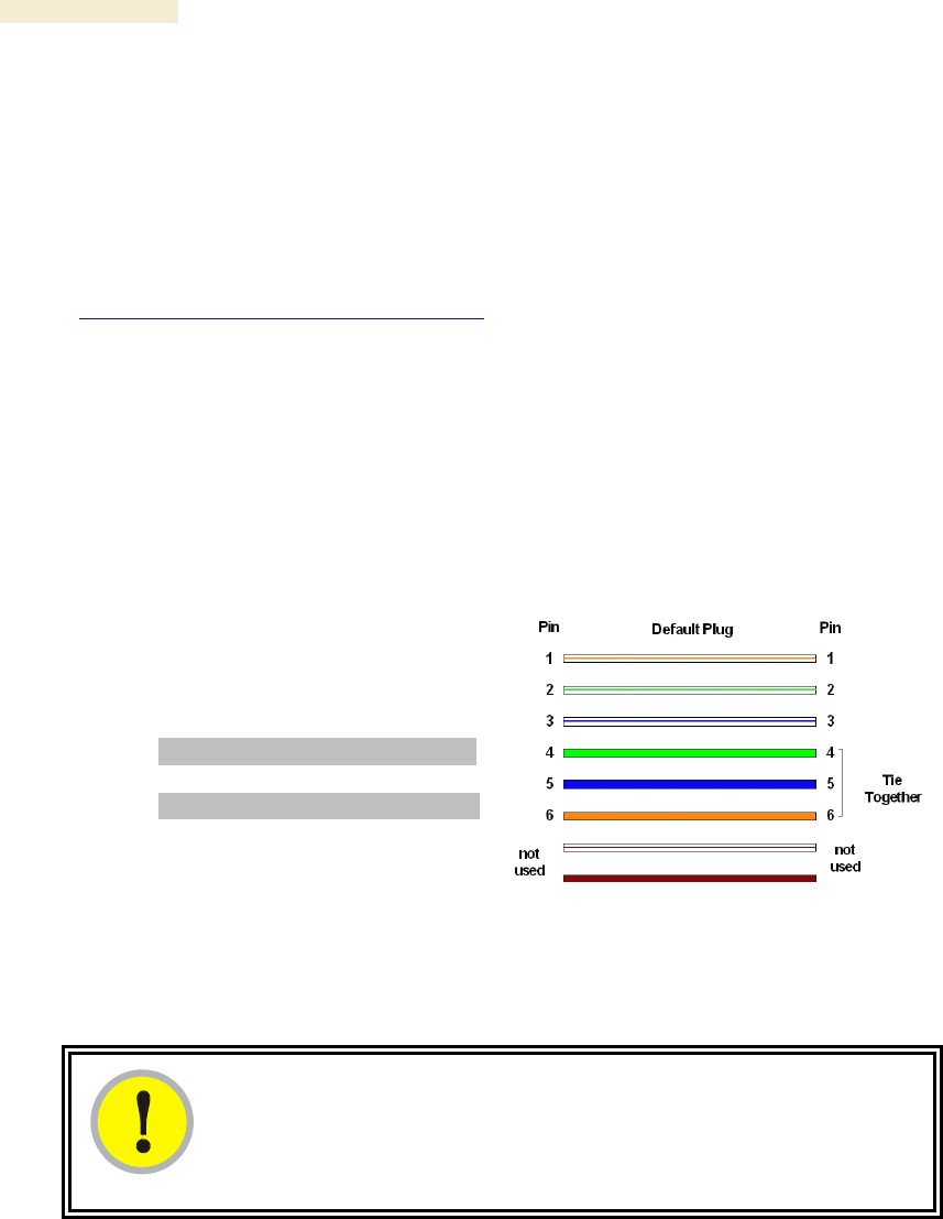
Procedure 36: Fabricating an override plug
1. Install an RJ-11 6-pin connector onto a 6-inch length of CAT 5 cable.
2. Pin out all 6-pins.
3. Short (solder together) Pins 4 and 6 on the other end. Do not connect any other
wires to anything. The result should be as shown in Figure 146.
=========================== end of procedure ===========================
Pin 1 → white / orange ← Pin 1
Pin 2 → white / green ← Pin 2
Pin 3 → white / blue ← Pin 3
Pin 4 → green ← Pin 6
Pin 5 → blue ← Pin 5
Pin 6 → orange ← Pin 4
Figure 146: RJ-11 pinout for the override plug
Using the Override Plug
IMPORTANT!
While the override plug is connected to a module, the module can neither
register nor allow registration of another module.
To regain access to the module, perform the following steps.
Procedure 37: Regaining access to a module
1. Insert the override plug into the RJ-11 GPS utility port of the module.
2. Power cycle by removing, then re-inserting, the Ethernet cable.
RESULT: The module boots with the default IP address of 169.254.1.1, password
fields blank, and all other configuration values as previously set.
3. Wait approximately 30 seconds for the boot to complete.
Release 8 Operations Guide
Issue 2, December 2006 Draft 2 for Regulatory Review 377
4. Remove the override plug.
5. Set passwords and IP address as desired.
6. Change configuration values if desired.
7. Click the Save Changes button.
8. Click the Reboot button.
=========================== end of procedure ===========================
22.3.3 Overriding Forgotten IP Addresses or Passwords on CMMmicro
By using an override toggle switch on the CMMmicro circuit board, you can temporarily
override a lost or unknown IP address or password as follows:
◦ Up is the override position in which a power cycle causes the CMMmicro to boot
with the default IP address (169.254.1.1) and no password required.
◦ Down is the normal position in which a power cycle causes the CMMmicro to
boot with your operator-set IP address and password(s).
To override a lost or unknown IP address or password, perform the following steps.
Procedure 38: Using the override switch to regain access to CMMmicro
IMPORTANT!
In override mode
◦ a CMMmicro provides no power on its ports.
◦ any APs or BHs connected to the CMMmicro are not powered.
◦ you cannot gain browser access to the CMMmicro through any
connected APs or BHs.
1. Gain physical access to the inside of the CMMmicro enclosure.
2. Establish direct Ethernet connectivity to the CMMmicro (not through an AP or
BH).
3. Flip the toggle switch up (toward you).
4. Power cycle the CMMmicro.
RESULT: The module reboots with the default IP address of 169.254.1.1,
password fields blank, and all other configuration values as previously set.
5. Set passwords as desired, or enter a blank space to set no password.
6. Change configuration values if desired.
7. Click the Save Changes button.
8. Flip the toggle switch down (away from you).
9. Click the Reboot button.
=========================== end of procedure ===========================
22.4 REQUIRING SM AUTHENTICATION
Through the use of Prizm Release 2.0 or later, or BAM Release 2.1, you can enhance
network security by requiring SMs to authenticate when they register. Three keys and a
random number are involved in authentication as follows:

Operations Guide Release 8
378 Draft 2 for Regulatory Review Issue 2, December 2006
◦ factory-set key in each SM. Neither the subscriber nor the network operator can
view or change this key.
◦ authentication key, also known as authorization key and skey. This key matches
in the SM and AP as the Authentication Key parameter, and in the Prizm
database.
◦ random number, generated by Prizm or BAM and used in each attempt by an SM
to register and authenticate. The network operator can view this number.
◦ session key, calculated separately by the SM and Prizm or BAM, based on both
the authentication key (or, by default, the factory-set key) and the random
number. Prizm or BAM sends the session key to the AP. The network operator
cannot view this key.
None of the above keys is ever sent in an over-the-air link during an SM registration
attempt. However, with the assumed security risk, the operator can create and configure
the Authentication Key parameter. See Authentication Key on Page 283.
22.5 FILTERING PROTOCOLS AND PORTS
You can filter (block) specified protocols and ports from leaving the SM and entering the
Canopy network. This protects the network from both intended and inadvertent packet
loading or probing by network users. By keeping the specified protocols or ports off the
network, this feature also provides a level of protection to users from each other.
Protocol and port filtering is set per SM. Except for filtering of SNMP ports, filtering occurs
as packets leave the SM. If an SM is configured to filter SNMP, then SNMP packets are
blocked from entering the SM and, thereby, from interacting with the SNMP portion of the
protocol stack on the SM.
22.5.1 Port Filtering with NAT Enabled
Where NAT is enabled, you can filter only the three user-defined ports. The following are
example situations in which you can configure port filtering where NAT is enabled.
◦ To block a subscriber from using FTP, you can filter Ports 20 and 21 (the FTP
ports) for both the TCP and UDP protocols.
◦ To block a subscriber from access to SNMP, you can filter Ports 161 and 162
(the SNMP ports) for both the TCP and UDP protocols.
NOTE: In only the SNMP case, filtering occurs before the packet interacts with
the protocol stack.
22.5.2 Protocol and Port Filtering with NAT Disabled
Where NAT is disabled, you can filter both protocols and the three user-defined ports.
Using the check boxes on the interface, you can either
◦ allow all protocols except those that you wish to block.
◦ block all protocols except those that you wish to allow.
You can allow or block any of the following protocols:
◦ PPPoE (Point to Point Protocol over Ethernet)
◦ Any or all of the following IPv4 (Internet Protocol version 4) protocols:
− SMB (Network Neighborhood)
− SNMP

Release 8 Operations Guide
Issue 2, December 2006 Draft 2 for Regulatory Review 379
− Up to 3 user-defined ports
− All other IPv4 traffic (see Figure 147)
◦ Uplink Broadcast
◦ ARP (Address Resolution Protocol)
◦ All others (see Figure 147)
PPPoE ARP
All Other IPv4
User
Defined
Port 1
IPv4
Multicast
BootP
Server
BootP
Client
SNMP
SMB
User
Defined
Port 3
User
Defined
Port 2
All Others
Figure 147: Categorical protocol filtering
The following are example situations in which you can configure protocol filtering where
NAT is disabled:
◦ If you block a subscriber from only PPoE and SNMP, then the subscriber retains
access to all other protocols and all ports.
◦ If you block PPoE, IPv4, and Uplink Broadcast, and you also check the
All others selection, then only Address Resolution Protocol is not filtered.
The ports that are filtered as a result of protocol selections in the Protocol Filtering tab of
the SM are listed in Table 59. Further information is provided under Protocol Filtering Tab
of the SM on Page 289.

Operations Guide Release 8
380 Draft 2 for Regulatory Review Issue 2, December 2006
Table 59: Ports filtered per protocol selections
Protocol
Selected
Port Filtered (Blocked)
SMB
Destination Ports 137 TCP and UDP,
138 UDP, 139 TCP, 445 TCP
SNMP
Destination Ports 161 TCP and UDP,
162 TCP and UDP
Bootp Client
Source Port 68 UDP
Bootp Server
Source Port 67 UDP
22.6 ENCRYPTING DOWNLINK BROADCASTS
An AP can be enabled to encrypt downlink broadcast packets such as the following:
◦ ARP
◦ NetBIOS
◦ broadcast packets containing video data on UDP.
The encryption used is DES for a DES module, and AES for an AES module. Before the
Encrypt Downlink Broadcast feature is enabled on the AP, air link security should be
enabled on the AP.
22.7 ISOLATING SMs
In the Release 8 or later AP, you can prevent SMs in the sector from directly
communicating with each other. In CMMmicro Release 2.2 or later, you can prevent
connected APs from directly communicating with each other, which prevents SMs that
are in different sectors of a cluster from communicating with each other.
In the AP, the SM Isolation parameter is available in the General tab of the Configuration
web page. In the drop-down menu for that parameter, you can configure the SM Isolation
feature by any of the following selections:
◦ Disable SM Isolation (the default selection). This allows full communication
between SMs.
◦ Block SM Packets from being forwarded. This prevents both
multicast/broadcast and unicast SM-to-SM communication.
◦ Block and Forward SM Packets to Backbone. This not only prevents
multicast/broadcast and unicast SM-to-SM communication but also sends the
packets, which otherwise would have been handled SM to SM, through the
Ethernet port of the AP.
In the CMMmicro, SM isolation treatment is the result of how you choose to manage the
port-based VLAN feature of the embedded switch, where you can switch all traffic from
any AP or BH to an uplink port that you specify. However, this is not packet level
switching. It is not based on VLAN IDs. See the VLAN Port Configuration parameter in
Figure 78: Configuration page of CMMmicro, example on Page 224.

Release 8 Operations Guide
Issue 2, December 2006 Draft 2 for Regulatory Review 381
22.8 FILTERING MANAGEMENT THROUGH ETHERNET
You can configure the SM to disallow any device that is connected to its Ethernet port
from accessing the IP address of the SM. If you set the Ethernet Access Control
parameter to Enabled, then
◦ no attempt to access the SM management interface (by http, SNMP, telnet, ftp,
or tftp) through Ethernet can succeed.
◦ any attempt to access the SM management interface over the air (by IP address,
presuming that LAN1 Network Interface Configuration, Network Accessibility
is set to Public, or by link from the Session Status or Remote Subscribers tab in
the AP) is unaffected.
22.9 ALLOWING MANAGEMENT FROM ONLY SPECIFIED IP
ADDRESSES
The Security tab of the Configuration web page in the AP, SM, and BH includes the IP
Access Control parameter. You can specify one, two, or three IP addresses that should
be allowed to access the management interface (by http, SNMP, telnet, ftp, or tftp).
If you select
◦ IP Access Filtering Disabled, then management access is allowed from any IP
address, even if the Allowed Source IP 1 to 3 parameters are populated.
◦ IP Access Filtering Enabled, and specify at least one address in the Allowed
Source IP 1 to 3 parameter, then management access is limited to the specified
address(es). If you intend to use Prizm to manage the element, then you must
ensure that the IP address of the Prizm server is listed here.
22.10 CONFIGURING MANAGEMENT IP BY DHCP
The IP tab in the Configuration web page of every Canopy radio contains a
LAN1 Network Interface Configuration, DHCP State parameter that, if enabled,
causes the IP configuration (IP address, subnet mask, and gateway IP address) to be
obtained through DHCP instead of the values of those individual parameters. The setting
of this DHCP state parameter is also viewable, but not settable, in the Network Interface
tab of the Home page.
In the SM, this parameter is settable
◦ in the NAT tab of the Configuration web page, but only if NAT is enabled.
◦ in the IP tab of the Configuration web page, but only if the
Network Accessibility parameter in the IP tab is set to Public.

Release 8 Operations Guide
Issue 2, December 2006 Draft 2 for Regulatory Review 383
23 MANAGING BANDWIDTH AND
AUTHENTICATION
This section provides a high-level description of bandwidth and authentication
management in a Canopy network. For more specific information, see Canopy Bandwidth
and Authentication Manager (BAM) User Guide or the Motorola Canopy Prizm User
Guide.
23.1 MANAGING BANDWIDTH WITHOUT BAM
Unless Prizm or BAM is deployed and is configured in the AP, bandwidth management is
limited to applying a single sustained data rate value (for uplink and for downlink) and a
single burst allocation value (for uplink and for downlink) to every SM that registers in
the AP.
23.2 BANDWIDTH AND AUTHENTICATION MANAGER (BAM)
SERVICES AND FEATURES
Prizm or BAM enables you to perform the following management operations on SMs:
◦ Change the key that the SMs need for authenticating.
◦ Temporarily suspend or reinstate a subscriber.
◦ Set burst size and data transfer rate caps for an SM or group of SMs.
◦ Use licensing to uncap an SM or group of SMs.
◦ List all ESNs that are associated with a specified VLAN ID.
◦ Associate or dissociate an SM or group of SMs with a specified VLAN ID.
◦ Set VLAN parameters.
◦ Toggle whether to send those VLAN parameters to the SMs.
◦ Set CIR parameters for low-priority and high-priority channel rates.
◦ Toggle whether to send those CIR parameters to the SMs.
◦ Toggle whether to enable the high-priority channel in the SMs.
23.2.1 Bandwidth Manager Capability
Prizm or BAM allows you to set bandwidth per SM for sustained rates and burst rates.
With this capability, the Canopy system allows both
◦ burst rates beyond those of many other broadband access solutions.
◦ control of average bandwidth allocation to prevent excessive bandwidth usage by
a subscriber.
All packet throttling occurs in the SMs and APs based on Quality of Service (QoS) data
that the Prizm or BAM server provides. No server processing power or network
messages are needed for packet throttling.
QoS management also supports marketing of broadband connections at various data
rates, for operator-defined groups of subscribers, and at various price points. This allows
you to meet customer needs at a price that the customer deems reasonable and
affordable.
When BAM is enabled in the AP Configuration page, bandwidth management is
expanded to apply uniquely specified sustained data rate and burst allocation values to
each registered SM. Thus, you can define differently priced tiers of subscriber service.

Operations Guide Release 8
384 Draft 2 for Regulatory Review Issue 2, December 2006
Designing Tiered Subscriber Service Levels
Examples of levels of service that vary by bandwidth capability are provided in Table 60
and Table 61.
NOTE:
The speeds that these tables correlate to service levels are comparative
examples. Actual download times may be greater due to use of the bandwidth
by other SMs, congestion on the local network, congestion on the Internet,
capacity of the serving computer, or other network limitations.
Table 60: Example times to download for arbitrary tiers of service with Canopy AP
AP
Canopy
SM
Canopy
Operation
1X
Equipment
Max burst speed
4.4 Mbps
Service Type
Premium
Regular
Basic
Sustained Downlink
Data Rate
5250
Kbps
1000
Kbps
256
Kbps
Sustained Uplink
Data Rate
1750
Kbps
500
Kbps
128
Kbps
Example Settings
Downlink and Uplink
Burst Allocations
500000
Kb
80000
Kb
40000
Kb
Web page
<1
<1
<1
5 MB
9
9
9
20 MB
36
80
470
50 MB
91
320
1400
Download (sec)
300 MB
545
2320
9220

Release 8 Operations Guide
Issue 2, December 2006 Draft 2 for Regulatory Review 385
Table 61: Example times to download for arbitrary tiers of service with Advantage AP
AP
Advantage
Advantage
SM
Canopy
Advantage
Operation
1X
2X
2X
Equipment
Max burst speed
5 Mbps
10 Mbps
10 Mbps
Service Type
Premium
Regular
Basic
Premium
Regular
Basic
Premium
Sustained
Downlink
Data Rate
5250
Kbps
1000
Kbps
256
Kbps
5250
Kbps
1000
Kbps
256
Kbps
2000
Kbps
Sustained Uplink
Data Rate
1750
Kbps
500
Kbps
128
Kbps
1750
Kbps
500
Kbps
128
Kbps
20000
Kbps
Example Settings
Downlink and
Uplink
Burst
Allocations
500000
Kb
80000
Kb
40000
Kb
500000
Kb
80000
Kb
40000
Kb
500000
Kb
Web page
<1
<1
<1
<1
<1
<1
<1
5 MB
8
8
8
4
4
4
4
20 MB
32
80
470
16
80
470
16
50 MB
80
320
1400
40
320
1400
40
Download (sec)
300 MB
480
2320
9220
362
2320
9220
240
23.2.2 Authentication Manager Capability
Prizm or BAM allows you to set per AP a requirement that each SM registering to the AP
must authenticate. When AP Authentication Server (APAS) is enabled in the AP, any SM
that attempts to register to the AP is denied service if authentication fails, such as (but
not limited to) when no Prizm or BAM server is operating or when the SM is not listed in
the database.
If a Prizm or BAM server drops out of service where no redundant server exists
◦ an SM that attempts to register is denied service.
◦ an SM that is already in session remains in session
In a typical Canopy network, some SMs re-register daily (when subscribers power down
the SMs, for example), and others do not re-register in a period of several weeks.
Whenever an authentication attempt fails, the SM locks out of any other attempt to
register itself to the same AP for the next 15 minutes.

Release 8 Operations Guide
Issue 2, December 2006 Draft 2 for Regulatory Review 387
24 MANAGING THE NETWORK FROM A
MANAGEMENT STATION (NMS)
SNMPv2 (Simple Network Management Protocol Version 2) can be used to manage and
monitor the Canopy modules under SMI (Structure of Management Information)
specifications. SMI specifies management information definitions in ASN.1 (Abstract
Syntax Notation One) language. SNMPv2 supports both 32-bit and 64-bit counters. The
SMI for SNMPv2 is defined in RFC 1902 at http://www.faqs.org/rfcs/rfc1902.html.
24.1 ROLES OF HARDWARE AND SOFTWARE ELEMENTS
24.1.1 Role of the Agent
In SNMP, software on each managed device acts as the agent. The agent collects and
stores management information in ASN.1 format, in a structure that a MIB (management
information base) defines. The agent responds to commands to
◦ send information about the managed device.
◦ modify specific data on the managed device.
24.1.2 Role of the Managed Device
In SNMP, the managed device is the network element that operates on the agent
software. In the Canopy network, this managed device is the module (AP, SM, or BH).
With the agent software, the managed device has the role of server in the context of
network management.
24.1.3 Role of the NMS
In SNMP, the NMS (network management station) has the role of client. An application
(manager software) operates on the NMS to manage and monitor the modules in the
network through interface with the agents.
24.1.4 Dual Roles for the NMS
The NMS can simultaneously act as an agent. In such an implementation, the NMS acts
as
◦ client to the agents in the modules, when polling for the agents for information
and sending modification data to the agents.
◦ server to another NMS, when being polled for information gathered from the
agents and receiving modification data to send to the agents.
24.1.5 Simple Network Management Protocol (SNMP) Commands
To manage a module, SNMPv2 supports the set command, which instructs the agent to
change the data that manages the module.

Operations Guide Release 8
388 Draft 2 for Regulatory Review Issue 2, December 2006
To monitor a network element (Canopy module), SNMPv2 supports
◦ the get command, which instructs the agent to send information about the
module to the manager in the NMS.
◦ traversal operations, which the manager uses to identify supported objects and to
format information about those objects into relational tables.
In a typical Canopy network, the manager issues these commands to the agents of more
than one module (to all SMs in the operator network, for example).
24.1.6 Traps from the Agent
When a specified event occurs in the module, the agent initiates a trap, for which the
agent sends an unsolicited asynchronous message to the manager.
24.1.7 AP SNMP Proxy to SMs
When the AP receives from Prizm or an NMS an SNMP request for an SM, it is capable
of sending that request via proxy to the SM. In this case, the SM responds directly to
Prizm or the NMS. (The AP performs no processing on the response.)
24.2 MANAGEMENT INFORMATION BASE (MIB)
The MIB, the SNMP-defined data structure, is a tree of standard branches that lead to
optional,
non-standard positions in the data hierarchy. The MIB contains both
◦ objects that SNMP is allowed to control (bandwidth allocation or access, for
example)
◦ objects that SNMP is allowed to monitor (packet transfer, bit rate, and error data,
for example).
The path to each object in the MIB is unique to the object. The endpoint of the path is the
object identifier.
24.2.1 Cascading Path to the MIB
The standard MIB hierarchy includes the following cascading branch structures:
◦ the top (standard body) level:
− ccitt (0)
− iso (1)
− iso-ccitt (2)
◦ under iso (1) above:
− standard (0)
− registration-authority (1)
− member-body (2)
− identified-organization (3)
◦ under identified-organization (3) above:
− dod (6)
− other branches
◦ under dod (6) above:

Release 8 Operations Guide
Issue 2, December 2006 Draft 2 for Regulatory Review 389
− internet (1)
− other branches
◦ under internet (1) above:
− mgmt (2)
− private (4)
− other branches
◦ under mgmt (2) above: mib-2 (1) and other branches. (See MIB-II below.)
under private (4) above: enterprise (1) and other branches. (See Canopy
Enterprise MIB below.)
Beneath this level are non-standard branches that the enterprise may define.
Thus, the path to an object that is managed under MIB-II begins with the decimal string
1.3.6.1.2.1 and ends with the object identifier and instance(s), and the path to an object
that is managed under the Canopy Enterprise MIB begins with 1.3.6.1.4.1, and ends with
the object identifier and instance(s).
24.2.2 Object Instances
An object in the MIB can have either only a single instance or multiple instances, as
follows:
◦ a scalar object has only a single instance. A reference to this instance is
designated by .0, following the object identifier.
◦ a tabular object has multiple instances that are related to each other. Tables in
the MIB associate these instances. References to these instances typically are
designated by .1, .2, and so forth, following the object identifier.
24.2.3 Management Information Base Systems and Interface (MIB-II)
The standard MIB-II (Management Information Base systems and interface) objects are
programmed into the Canopy modules. To read this MIB, see Management Information
Base for Network Management of TCP/IP-based Internets: MIB II, RFC 1213 at
http://www.faqs.org/rfcs/rfc1213.html.
The MIB-II standard categorizes each object as one of the types defined in Table 62.
Table 62: Categories of MIB-II objects
Objects in
category…
Control or identify the status of…
system
system operations in the module.
interfaces
the network interfaces for which the module is configured.
ip
Internet Protocol information in the module.
icmp
Internet Control Message Protocol information in the module.
(These messages flag IP problems and allow IP links to be tested.)
tcp
Transport Control Protocol information in the module (to control
and ensure the flow of data on the Internet).
udp
User Datagram Protocol information in the module (for checksum
and address).

Operations Guide Release 8
390 Draft 2 for Regulatory Review Issue 2, December 2006
24.2.4 Canopy Enterprise MIB
The Canopy Enterprise MIB provides additional reporting and control, extending the
objects for any NMS that uses SNMP interaction. This MIB comprises five text files that
are formatted in standard ASN.1 (Abstract Syntax Notation One) language.
To use this MIB, perform the following steps.
Procedure 39: Installing the Canopy Enterprise MIB files
1. On the NMS, immediately beneath the root directory, create directory
mibviewer.
2. Immediately beneath the mibviewer directory, create directory canopymibs.
3. Download the following three standard MIB files from the Internet Engineering
Task Force at http://www.simpleweb.org/ietf/mibs into the
mibviewer/canopymibs directory on the NMS:
◦ SNMPv2-SMI.txt, which defines the Structure of Management Information
specifications.
◦ SNMPv2-CONF.txt, which allows macros to be defined for object group,
notification group, module compliance, and agent capabilities.
◦ SNMPv2-TC.txt, which defines general textual conventions.
4. Move the following five files from your Canopy software package directory into
the mibviewer/canopymibs directory on the NMS (if necessary, first
download the software package from http://www.motorola.com/canopy):
◦ whisp-tcv2-mib.txt (Textual Conventions MIB), which defines Canopy
system-specific textual conventions
◦ WHISP-GLOBAL-REG-MIB.txt (Registrations MIB), which defines
registrations for global items such as product identities and product
components.
◦ WHISP-BOX-MIBV2-MIB.txt (Box MIB), which defines module-level (AP,
SM, and BH) objects.
◦ WHISP-APS-MIB.txt (APs MIB), which defines objects that are specific to
the AP or BH timing master.
◦ WHISP-SM-MIB.txt (SM MIB), which defines objects that are specific to
the SM or BH timing slave.
◦ CMM3-MIB.txt (CMM3 MIB), which defines objects that are specific to the
CMMmicro.
IMPORTANT!
Do not edit these MIB files in ASN.1. These files are intended for manipulation
by only the NMS. However, you can view these files through a commercially
available MIB viewer. Such viewers are listed under MIB Viewers on Page 407.
5. Download a selected MIB viewer into directory mibviewer.
6. As instructed by the user documentation that supports your NMS, import the
eight MIB files that are listed above.
=========================== end of procedure ===========================
Release 8 Operations Guide
Issue 2, December 2006 Draft 2 for Regulatory Review 391
24.3 CONFIGURING MODULES FOR SNMP ACCESS
Canopy modules provide the following Configuration web page parameters in the SNMP
tab. These govern SNMP access from the manager to the agent:
◦ Community String, which specifies the password for security between
managers and the agent.
◦ Accessing Subnet, which specifies the subnet mask that allows managers to
poll the agents.
Canopy modules can also be configured to send traps to specified IP addresses, which
can be those of Prizm or NMS servers, for example. The parameter for this address is
named Trap Address.
24.4 OBJECTS DEFINED IN THE CANOPY ENTERPRISE MIB
The Canopy Enterprise MIB defines separate sets of objects for
◦ all radio modules
◦ APs and BH timing masters
◦ SMs and BH timing slaves
◦ CMMmicros
NOTE:
The OFDM Series BHs do not support these objects. The MIBs that they support
are listed under Objects Defined in the Canopy OFDM BH Module MIB on
Page 404.
24.4.1 AP, SM, and BH Objects
The objects that the Canopy Enterprise MIB defines for all APs, SMs, and BHs are listed
in Table 63.
Table 63: Canopy Enterprise MIB objects for APs, SMs, and BHs
AP, SM, BH
Object Name
Value Syntax
Operation
Allowed
addVlanMember
Integer
manage
agingTimeout
Integer
manage
allowVIDAccess
Integer
manage
antennaGain1
Integer
manage
bridgeEnable
Integer
manage
clearEventLog
Integer
manage
codePointn2
Integer
manage
commString
DisplayString
manage
deleteUser
DisplayString
manage

Operations Guide Release 8
392 Draft 2 for Regulatory Review Issue 2, December 2006
AP, SM, BH
Object Name
Value Syntax
Operation
Allowed
dynamicLearning
Integer
manage
eirp3
Integer
manage
extFilterDelay
Integer
manage
fecEnable
Integer
manage
lanDhcpState
Integer
manage
managementVID
Integer
manage
mngtIP
IpAddress
manage
powerControl
Integer
manage
reboot
Integer
manage
removeVlanMember
Integer
manage
scheduling
Integer
manage
sessionTimeout
Integer
manage
setDefaultPlug
Integer
manage
subnetMask
Integer
manage
taggedFrame4
Integer
manage
transmitterOP
Integer
manage
trapIPn5
IpAddress
manage
twoXRate
Integer
manage
userAccessLevel
Integer
manage
userName
DisplayString
manage
userPassword
DisplayString
manage
vlanMemberSource
Integer
manage
accessLevel
Integer
monitor
boxDeviceType
DisplayString
monitor
boxDeviceTypeID
DisplayString
monitor
boxEncryption
DisplayString
monitor
boxFrequency
DisplayString
monitor
boxTemperature6
DisplayString
monitor
dhcpLanIP
IpAddress
monitor
dhcpLanGateway
IpAddress
monitor
dhcpLanSubnetMask
IpAddress
monitor
dhcpRfPublicIP
IpAddress
monitor
dhcpRfPublicGateway
IpAddress
monitor
dhcpRfPublicSubnetMask
IpAddress
monitor

Release 8 Operations Guide
Issue 2, December 2006 Draft 2 for Regulatory Review 393
AP, SM, BH
Object Name
Value Syntax
Operation
Allowed
etherLinkStatus
DisplayString
monitor
inSyncCount
Integer
monitor
lanDhcpStatus
DisplayString
monitor
outSyncCount
Integer
monitor
platformType
Integer
monitor
platformVer
Integer
monitor
pllOutLockCount
Integer
monitor
rfPublicDhcpStatus
DisplayString
monitor
txCalFailure
Integer
monitor
userLoginName
DisplayString
monitor
userPswd
DisplayString
monitor
whispBoxBoot
DisplayString
monitor
whispBoxEsn
WhispMACAddress
monitor
whispBoxEvntLog
EventString
monitor
whispBoxFPGAVer
DisplayString
monitor
whispBridgeAge
Integer
monitor
whispBridgeDesLuid
WhispLUID
monitor
whispBridgeExt
Integer
monitor
whispBridgeHash
Integer
monitor
whispBridgeMacAddr
MacAddress
monitor
whispBridgeTbErr
Integer
monitor
whispBridgeTbFree
Integer
monitor
whispBridgeTbUsed
Integer
monitor
whispVAge
Integer
monitor

Operations Guide Release 8
394 Draft 2 for Regulatory Review Issue 2, December 2006
AP, SM, BH
Object Name
Value Syntax
Operation
Allowed
whispVID
Integer
monitor
whispVType
DisplayString
monitor
NOTES:
1. For only 5.7-GHz radios.
2. Where n is any number, 0 through 63. codePoint0,
codePoint48, and codePoint56 can be only monitored.
3. Deprecated.
4. Replaced by frameType.
5. Where n is any number, 1 through 10.
6. The value of this object does not accurately reflect the
temperature inside the module for comparison with the
operating range. However, it can be helpful as one of many
troubleshooting indicators. Although modules no longer
report the Temperature field in the GUI, the agent in the
modules continues to support this object.
24.4.2 AP and BH Timing Master Objects
The objects that the Canopy Enterprise MIB defines for each AP and BH Timing Master
are listed in Table 64. The traps provided in this set of objects are listed under Traps
Provided in the Canopy Enterprise MIB on Page 406.
Table 64: Canopy Enterprise MIB objects for APs and BH timing masters
AP, BHM
Object Name
Value Syntax
Operation
Allowed
allowedIPAccess1
IpAddress
manage
allowedIPAccess2
IpAddress
manage
allowedIPAccess3
IpAddress
manage
apBeaconInfo
Integer
manage
apTwoXRate
Integer
manage
asIP1
IpAddress
manage
asIP2
IpAddress
manage
asIP3
IpAddress
manage
authKey
DisplayString
manage
authMode
Integer
manage
configSource
Integer
manage
dAcksReservHigh
Integer
manage
defaultGw
IpAddress
manage
dfsConfig
Integer
manage
dwnLnkData
Integer
manage
dwnLnkDataRate
Integer
manage

Release 8 Operations Guide
Issue 2, December 2006 Draft 2 for Regulatory Review 395
AP, BHM
Object Name
Value Syntax
Operation
Allowed
dwnLnkLimit
Integer
manage
encryptDwBroadcast
Integer
manage
encryptionMode
Integer
manage
gpsInput
Integer
manage
gpsTrap
Integer
manage
highPriorityUpLnkPct
Integer
manage
ipAccessFilterEnable
Integer
manage
lanIp
IpAddress
manage
lanMask
IpAddress
manage
limitFreqBand900
Integer
manage
linkTestAction1
Integer
manage
linkTestDuration
Integer
manage
linkTestLUID
Integer
manage
maxRange
Integer
manage
ntpServerIP
IpAddress
manage
numCtlSlots
Integer
manage
numCtlSlotsHW
Integer
manage
numCtlSlotsReserveHigh
Integer
manage
numDAckSlots
Integer
manage
numUAckSlots
Integer
manage
privateIp
IpAddress
manage
regTrap
Integer
manage
rfFreqCarrier
Integer
manage
sectorID
Integer
manage
sesHiDownCIR
Integer
manage
sesHiUpCIR
Integer
manage
sesLoDownCIR
Integer
manage
sesHiDownCIR
Integer
manage
smIsolation
Integer
manage
tslBridging
Integer
manage
txSpreading
Integer
manage
uAcksReservHigh
Integer
manage
untranslatedArp
Integer
manage
updateAppAddress
IpAddress
manage

Operations Guide Release 8
396 Draft 2 for Regulatory Review Issue 2, December 2006
AP, BHM
Object Name
Value Syntax
Operation
Allowed
upLnkDataRate
Integer
manage
upLnkLimit
Integer
manage
vlanEnable
Integer
manage
actDwnFragCount
Gauge32
monitor
actDwnLinkIndex
Integer
monitor
actUpFragCount
Gauge32
monitor
adaptRate
DisplayString
monitor
avgPowerLevel
DisplayString
monitor
dataSlotDwn
Integer
monitor
dataSlotUp
Integer
monitor
dataSlotUpHi
Integer
monitor
Status
DisplayString
monitor
downLinkEff
Integer
monitor
downLinkRate
Integer
monitor
dwnLnkAckSlot
Integer
monitor
dwnLnkAckSlotHi
Integer
monitor
expDwnFragCount
Gauge32
monitor
expUpFragCount
Gauge32
monitor
fpgaVersion
DisplayString
monitor
gpsStatus
DisplayString
monitor
lastPowerLevel
DisplayString
monitor
linkAirDelay
Integer
monitor
linkAveJitter
Integer
monitor
linkDescr
DisplayString
monitor
linkESN
PhysAddress
monitor
linkInDiscards
Counter32
monitor
linkInError
Counter32
monitor
linkInNUcastPkts
Counter32
monitor
linkInOctets
Counter32
monitor
linkInUcastPkts
Counter32
monitor
linkInUnknownProtos
Counter32
monitor
linkLastJitter
Integer
monitor
linkLastRSSI
Integer
monitor
linkLUID
Integer
monitor

Release 8 Operations Guide
Issue 2, December 2006 Draft 2 for Regulatory Review 397
AP, BHM
Object Name
Value Syntax
Operation
Allowed
linkMtu
Integer
monitor
linkOutDiscards
Counter32
monitor
linkOutError
Counter32
monitor
linkOutNUcastPkts
Counter32
monitor
linkOutOctets
Counter32
monitor
linkOutQLen
Gauge32
monitor
linkOutUcastPkts
Counter32
monitor
linkRegCount
Integer
monitor
linkReRegCount
Integer
monitor
linkRSSI
Integer
monitor
linkSessState
Integer
monitor
linkSiteName
DisplayString
monitor
linkSpeed
Gauge32
monitor
linkTestError
DisplayString
monitor
linkTestStatus
DisplayString
monitor
linkTimeOut
Integer
monitor
maxDwnLinkIndex
Integer
monitor
numCtrSlot
Integer
monitor
numCtrSlotHi
Integer
monitor
PhysAddress
PhysAddress
monitor
radioSlicing
Integer
monitor
radioTxGain
Integer
monitor
regCount
Integer
monitor
sesDownlinkLimit
Integer
monitor
sesDownlinkRate
Integer
monitor
sesUplinkLimit
Integer
monitor
sesUplinkRate
Integer
monitor
sessionCount
Integer
monitor
softwareBootVersion
DisplayString
monitor
softwareVersion
DisplayString
monitor
testDuration
Integer
monitor
testLUID
Integer
monitor
upLinkEff
Integer
monitor
upLinkRate
Integer
monitor

Operations Guide Release 8
398 Draft 2 for Regulatory Review Issue 2, December 2006
AP, BHM
Object Name
Value Syntax
Operation
Allowed
upLnkAckSlot
Integer
monitor
upLnkAckSlotHi
Integer
monitor
whispGPSStats
Integer
monitor
NOTES:
1. You can set to 1 to initiate a link test, but not 0 to stop.
The value 0 is only an indication of the idle link test state.
24.4.3 SM and BH Timing Slave Objects
The objects that the Canopy Enterprise MIB defines for each SM and BH Timing Slave
are listed in Table 65.
Table 65: Canopy Enterprise MIB objects for SMs and BH timing slaves
SM, BHS
Object Name
Value Syntax
Operation
Allowed
allOtherIPFilter
Integer
manage
allOthersFilter
Integer
manage
allowedIPAccess1
IpAddress
manage
allowedIPAccess2
IpAddress
manage
allowedIPAccess3
IpAddress
manage
alternateDNSIP
IpAddress
manage
arpCacheTimeout
Integer
manage
arpFilter
Integer
manage
authKey
DisplayString
manage
authKeyOption
Integer
manage
bootpcFilter
Integer
manage
bootpsFilter
Integer
manage
defaultGw
IpAddress
manage
dhcpClientEnable
Integer
manage
dhcpIPStart
IpAddress
manage
dhcpNumIPsToLease
Integer
manage
dhcpServerEnable
Integer
manage
dhcpServerLeaseTime
Integer
manage
dmzEnable
Integer
manage
dmzIP
IpAddress
manage
dnsAutomatic
Integer
manage
enable8023link
Integer
manage

Release 8 Operations Guide
Issue 2, December 2006 Draft 2 for Regulatory Review 399
SM, BHS
Object Name
Value Syntax
Operation
Allowed
ethAccessFilterEnable
Integer
manage
hiPriorityChannel
Integer
manage
hiPriorityDownlinkCIR
Integer
manage
hiPriorityUplinkCIR
Integer
manage
ingressVID
Integer
manage
ip4MultFilter
Integer
manage
ipAccessFilterEnable
Integer
manage
lanIp
IpAddress
manage
lanMask
IpAddress
manage
localIP
IpAddress
manage
lowPriorityDownlinkCIR
Integer
manage
lowPriorityUplinkCIR
Integer
manage
naptEnable
Integer
manage
naptPrivateIP
IpAddress
manage
naptPrivateSubnetMask
IpAddress
manage
naptPublicGatewayIP
IpAddress
manage
naptPublicIP
IpAddress
manage
naptPublicSubnetMask
IpAddress
manage
naptRFPublicGateway
IpAddress
manage
naptRFPublicIP
IpAddress
manage
naptRFPublicSubnetMask
IpAddress
manage
networkAccess
Integer
manage
port
Integer
manage
port1TCPFilter
Integer
manage
port2TCPFilter
Integer
manage
port3TCPFilter
Integer
manage
port1UDPFilter
Integer
manage
port2UDPFilter
Integer
manage
port3UDPFilter
Integer
manage
powerUpMode
Integer
manage
pppoeFilter
Integer
manage
prefferedDNSIP
IpAddress
manage
protocol
Integer
manage
radioDbmInt
Integer
manage

Operations Guide Release 8
400 Draft 2 for Regulatory Review Issue 2, December 2006
SM, BHS
Object Name
Value Syntax
Operation
Allowed
rfDhcpState
Integer
manage
rfScanList
DisplayString
manage
smbFilter
Integer
manage
snmpFilter
Integer
manage
tcpGarbageCollectTmout
Integer
manage
timingPulseGated
Integer
manage
twoXRate
Integer
manage
udpGarbageCollectTmout
Integer
manage
uplinkBCastFilter
Integer
manage
userDefinedPort1
Integer
manage
userDefinedPort2
Integer
manage
userDefinedPort3
Integer
manage
userP1Filter
Integer
manage
userP2Filter
Integer
manage
userP3Filter
Integer
manage
adaptRate
DisplayString
monitor
airDelay
Integer
monitor
calibrationStatus
DisplayString
monitor
dhcpcdns1
IpAddress
monitor
dhcpcdns2
IpAddress
monitor
dhcpcdns3
IpAddress
monitor
dhcpCip
IpAddress
monitor
dhcpClientLease
TimeTicks
monitor
dhcpCSMask
IpAddress
monitor
dhcpDfltRterIP
IpAddress
monitor
dhcpDomName
DisplayString
monitor
dhcpServerTable
DhcpServerEntry
monitor
dhcpSip
IpAddress
monitor
hostIp
IpAddress
monitor
hostLease
TimeTicks
monitor
hostMacAddress
PhysAddress
monitor
jitter
Integer
monitor
radioDbm
DisplayString
monitor
radioSlicing
Integer
monitor