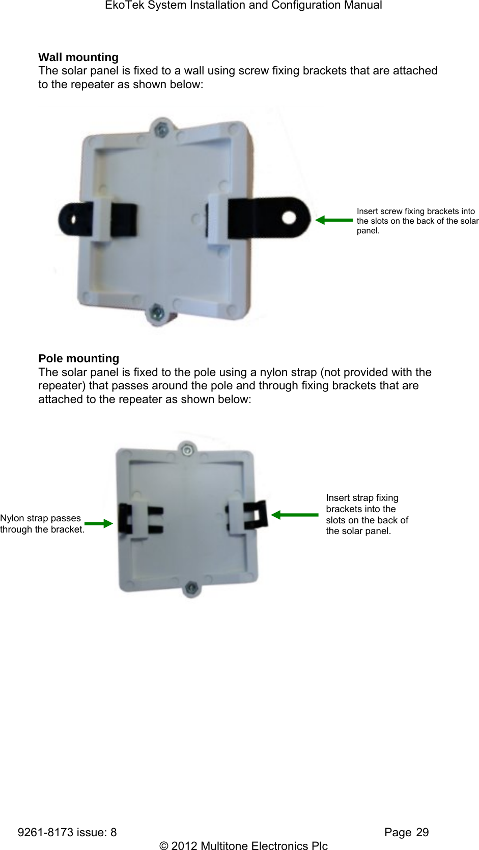
Multitone Electronics PLC EKOPAG Alpha-numeric 2 way alarm and paging device User Manual System manual
Multitone Electronics PLC Alpha-numeric 2 way alarm and paging device System manual
Contents
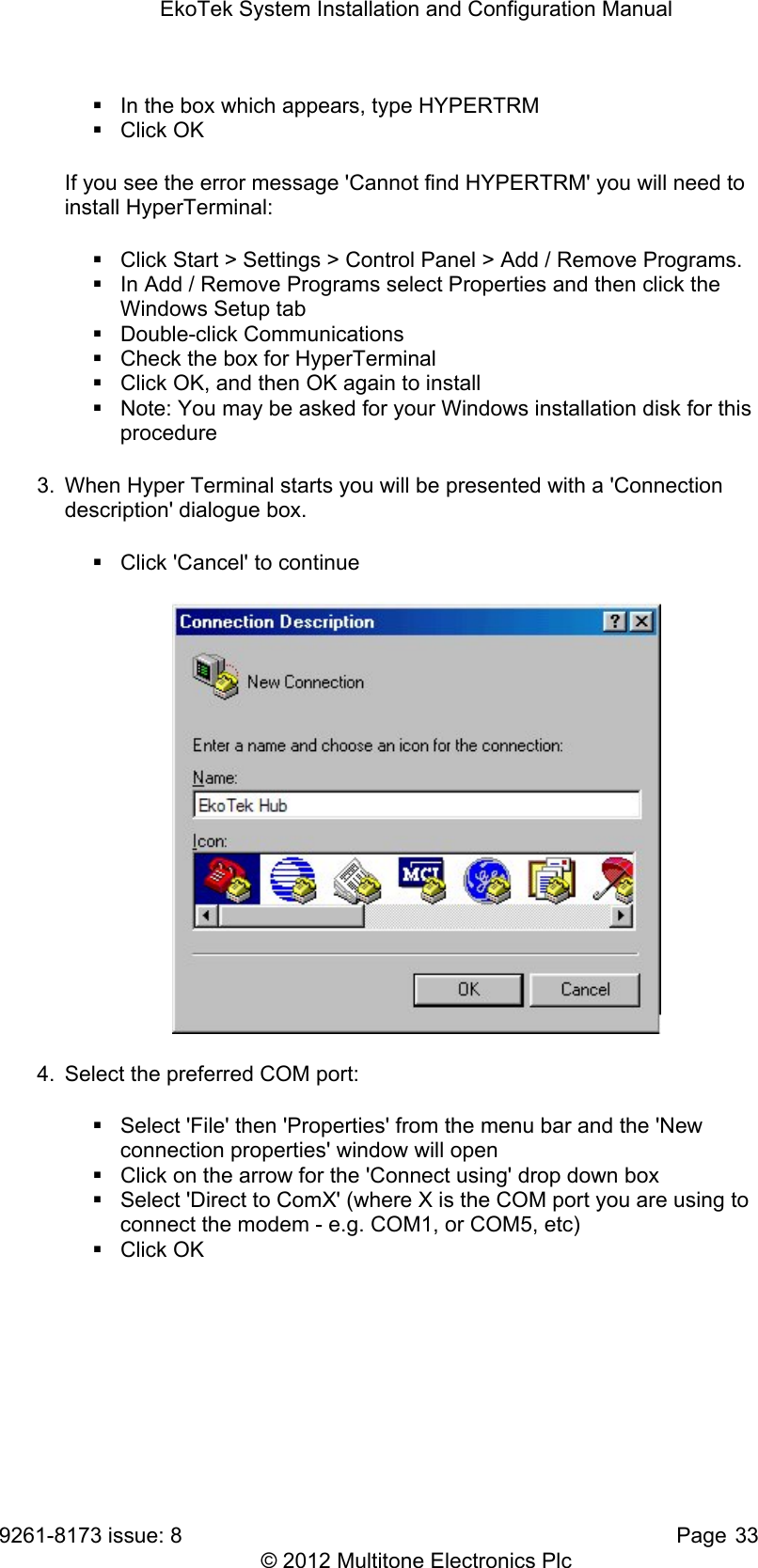
- 1. Quick Guide
- 2. Handy Guide
- 3. System manual
- 4. Data sheet
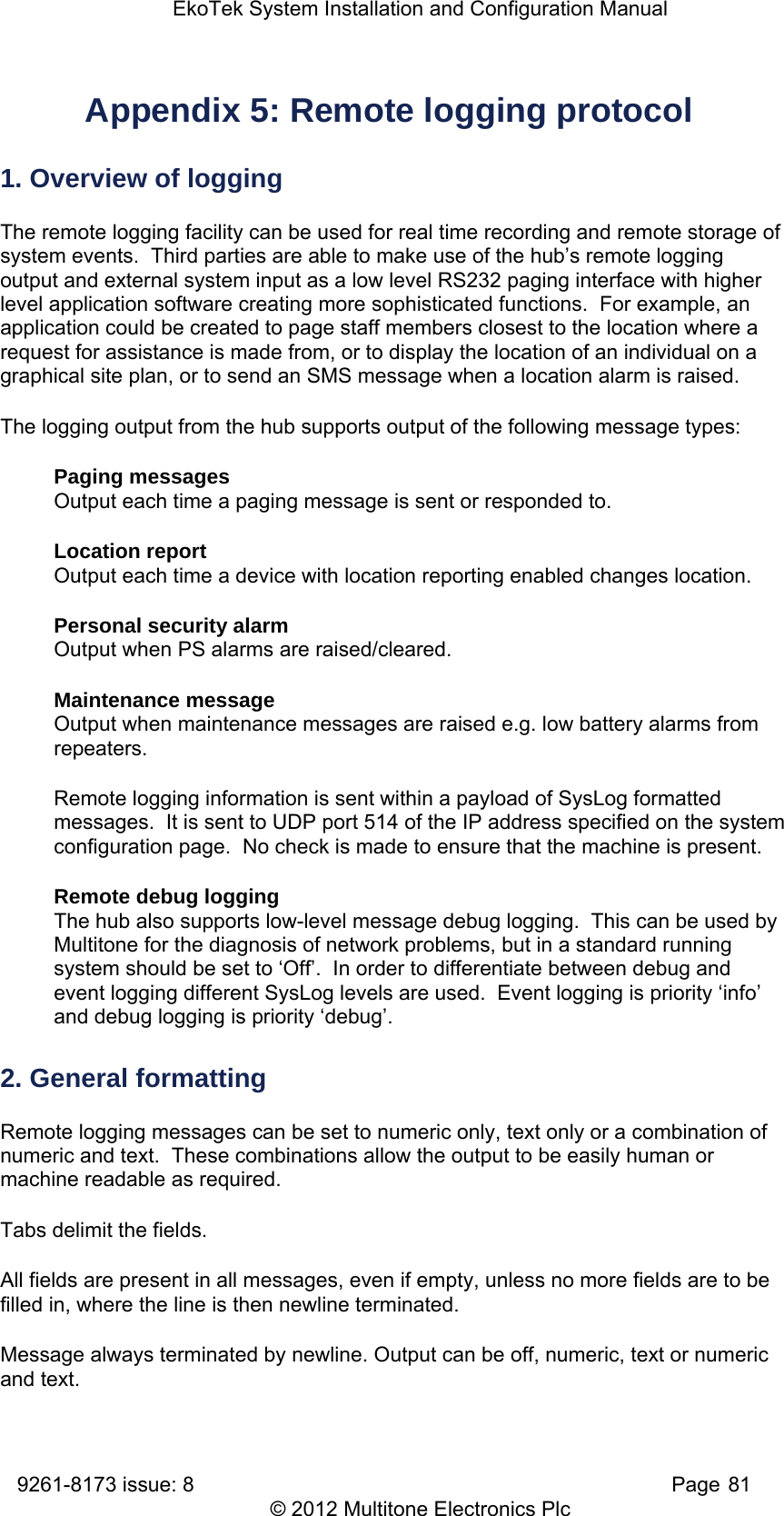
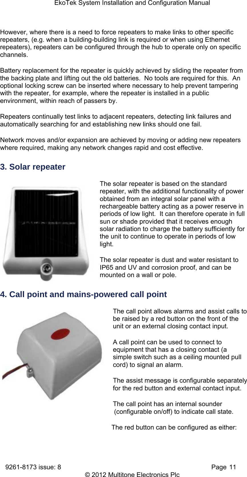
System manual

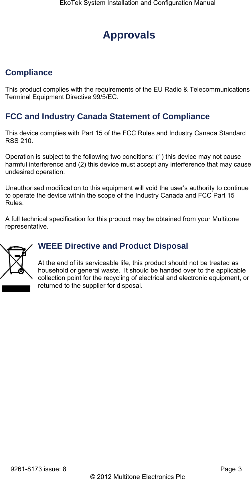
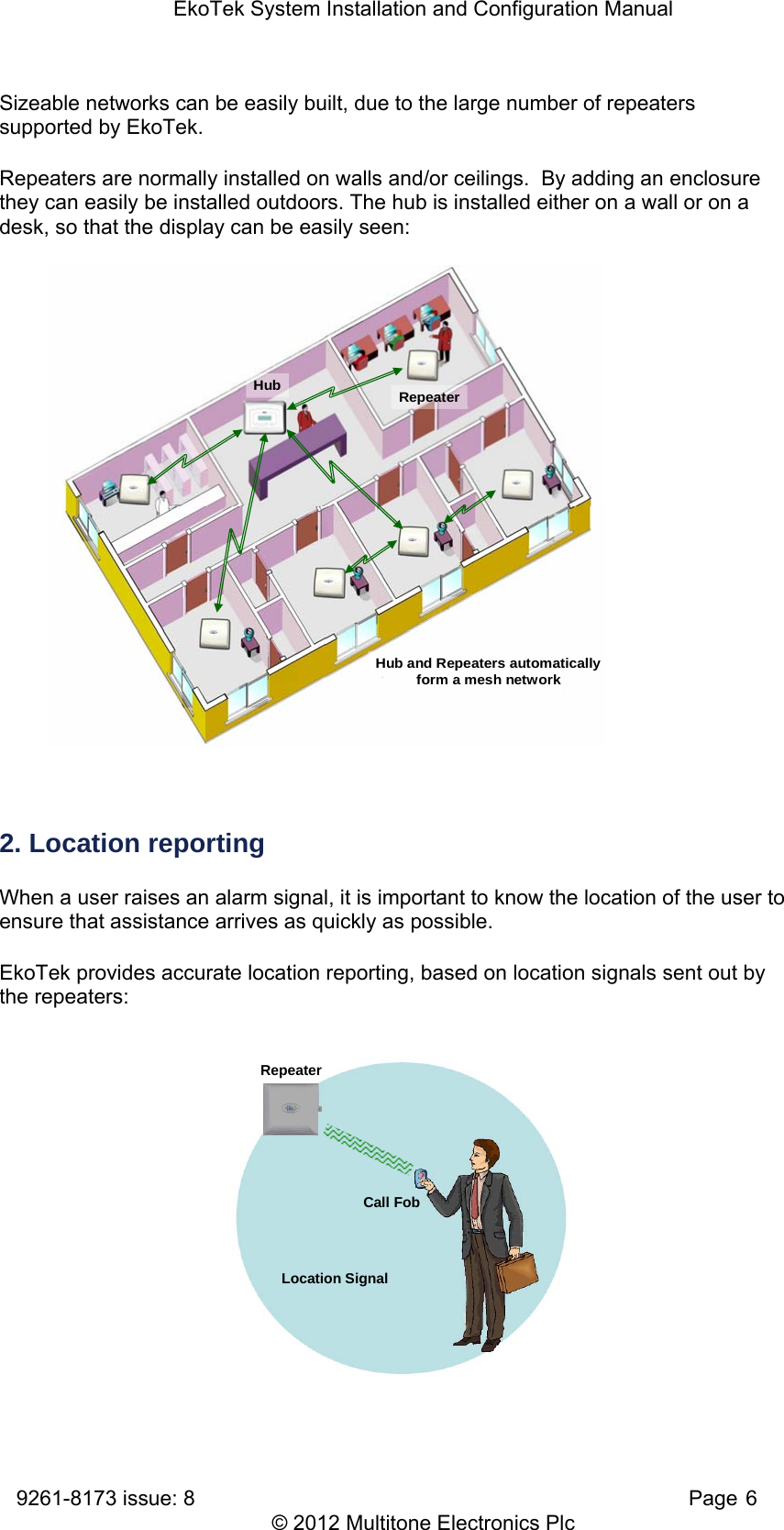
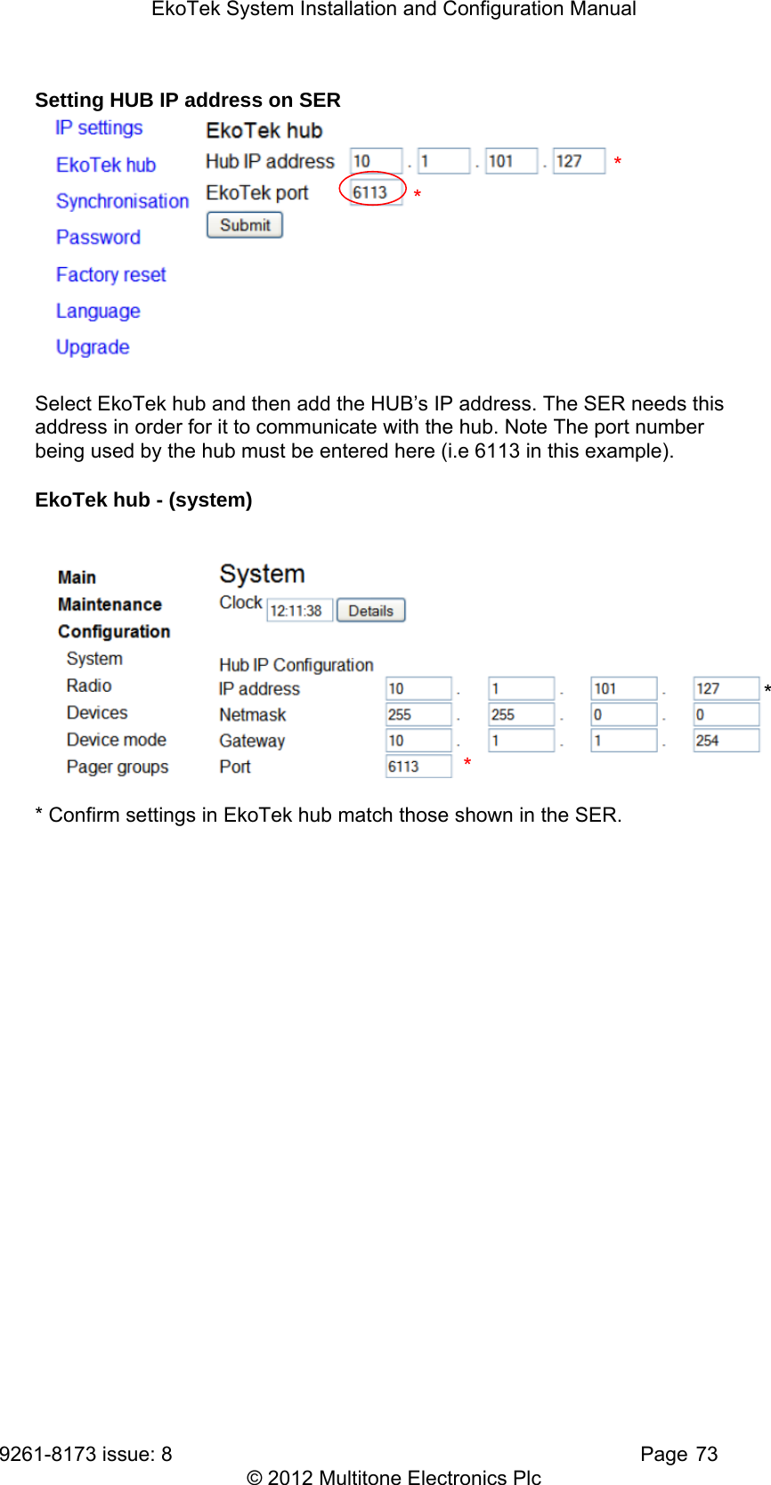
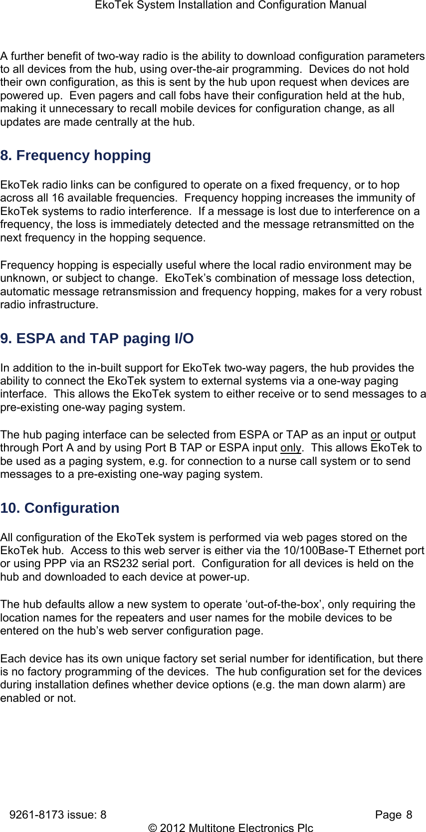
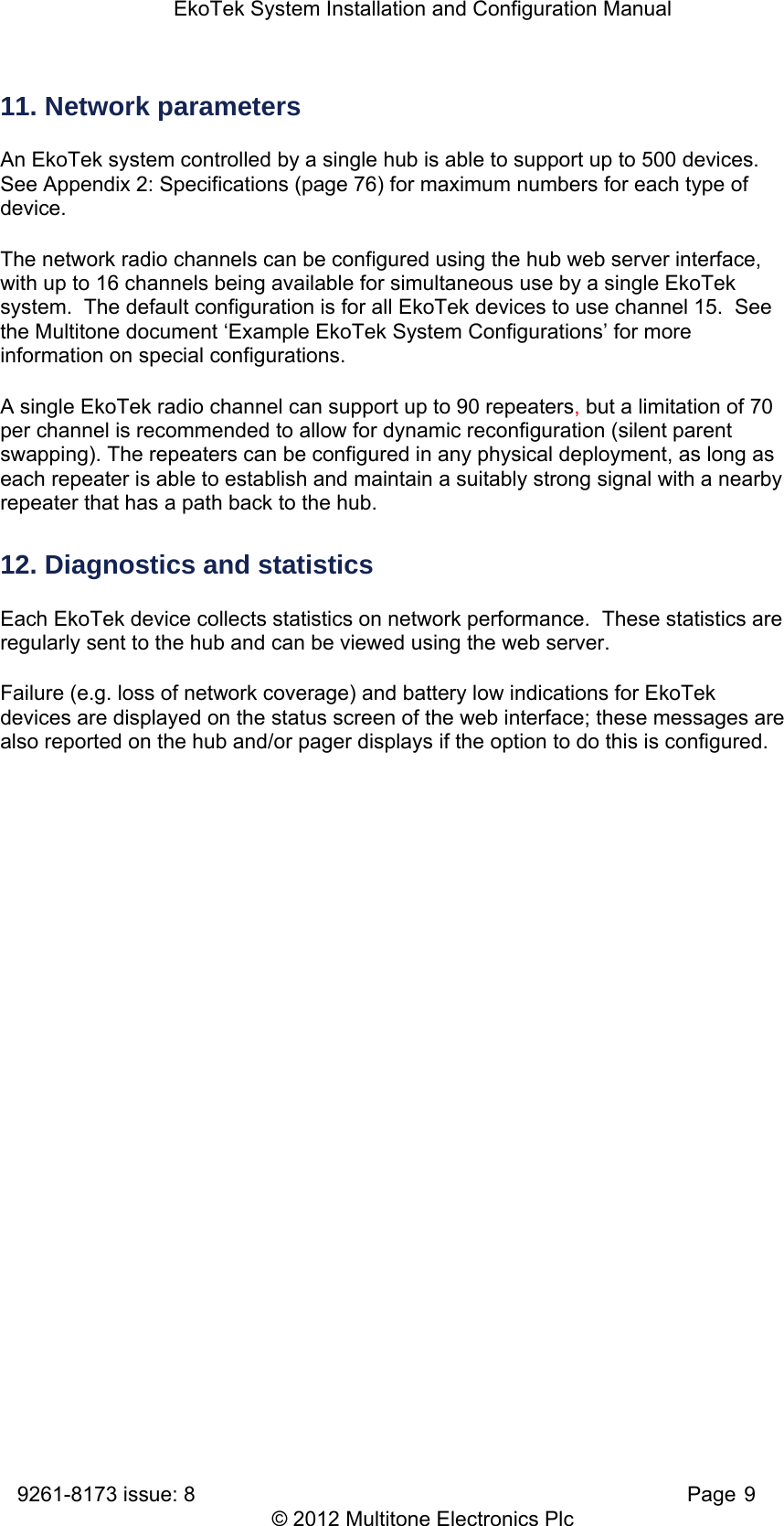
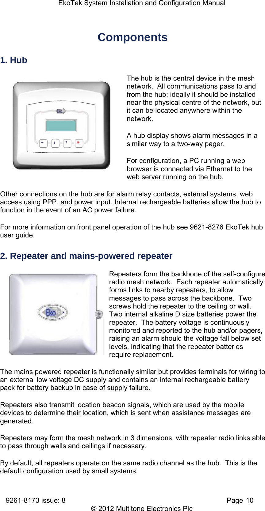
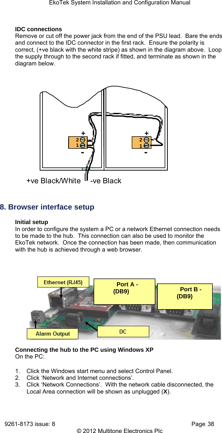
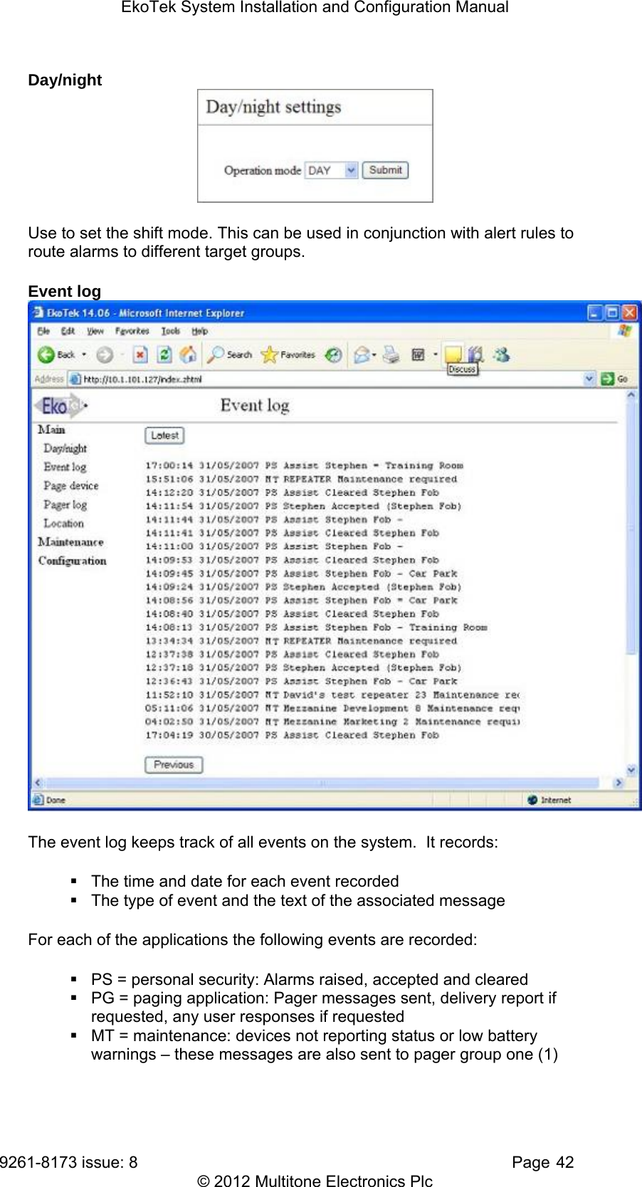
![EkoTek System Installation and Configuration Manual 9261-8173 issue: 8 Page 7 © 2012 Multitone Electronics Plc 3. Alarms A user may manually signal an alarm by pressing the red button on a pager or call fob, or alarms may be triggered automatically for man down, dead man or location alarms. When an alarm is triggered the user identification (name), location and alarm type are included in the alarm message displayed on the hub and sent to pagers. 4. Location alarm The location alarm feature allows pagers and call fobs to automatically raise an alarm should the device wearer enter a location where the local repeater indicates an unauthorised zone. Applications include ‘resident wander’, where an alarm would be raised if a resident wandered into a zone where they were not expected or not allowed, and ‘contractor/visitor’ location alarm where an alarm could be raised if a person entered a part of the building that they were not authorised to access. 5. Beacons Beacon signals are used to update a device with information of who its parent is. The hub and all repeaters regularly transmit two types of beacon – system beacons and location beacons. Location beacons generally have a shorter range than System beacons. A repeater, pager or call fob can only ever have one parent at a time. Every 1000ms the repeater transmits to the pager or call fob, which is then updated with its location and will continue to receive subsequent beacons from the repeater (its parent). If the pager stays within range of the location beacon the location will be shown on the pager's display, ‘= [location name]’ (for example, ‘= Conference Room 1’). If the pager goes out of range of the location beacon but can still receive the system beacon, ‘- [location name]’ will be shown instead, where [location name] is the name of the last location beacon received. When a pager or call fob receives a new location beacon it picks up location information from the new repeater and updates itself with the new location. 6. Two-way acknowledgement Messages from external systems and maintenance messages are one-way messages from the hub to the pager, whereas alarms generated by a user are two-way. For peace of mind of the user, the acceptance of an alarm at the hub or a pager by someone who will be coming to the aid of the user is signalled back to the user by the call fob lamp and beeper changing their alert patterns, or by the pager display indicating the status of the alarm. 7. Two-way radio All EkoTek radio links are two-way, providing the ability to signal both to and from all devices on the network. Two-way radio provides the ability to quickly detect and correct any lost messages, for example, when a message is relayed from one repeater to a second repeater, the second repeater will acknowledge receipt of the message. If the first repeater does not receive an acknowledgement it retransmits the message. This ability allows EkoTek to function, even in environments where there is radio interference or poor signal.](https://usermanual.wiki/Multitone-Electronics-PLC/EKOPAG.System-manual/User-Guide-1895899-Page-9.png)
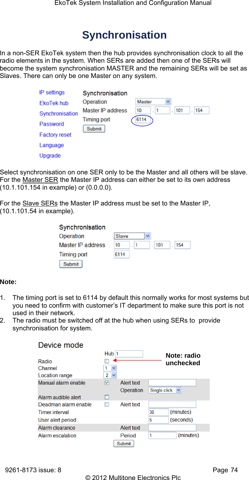
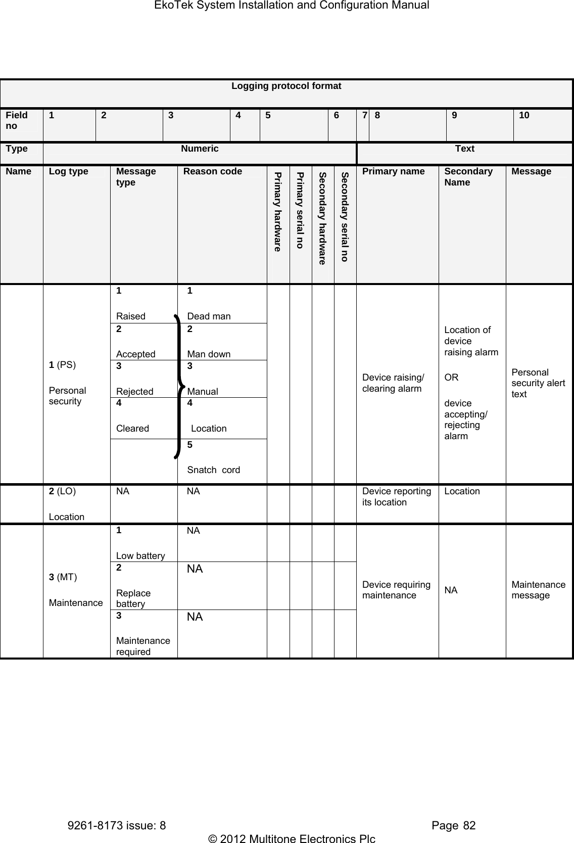
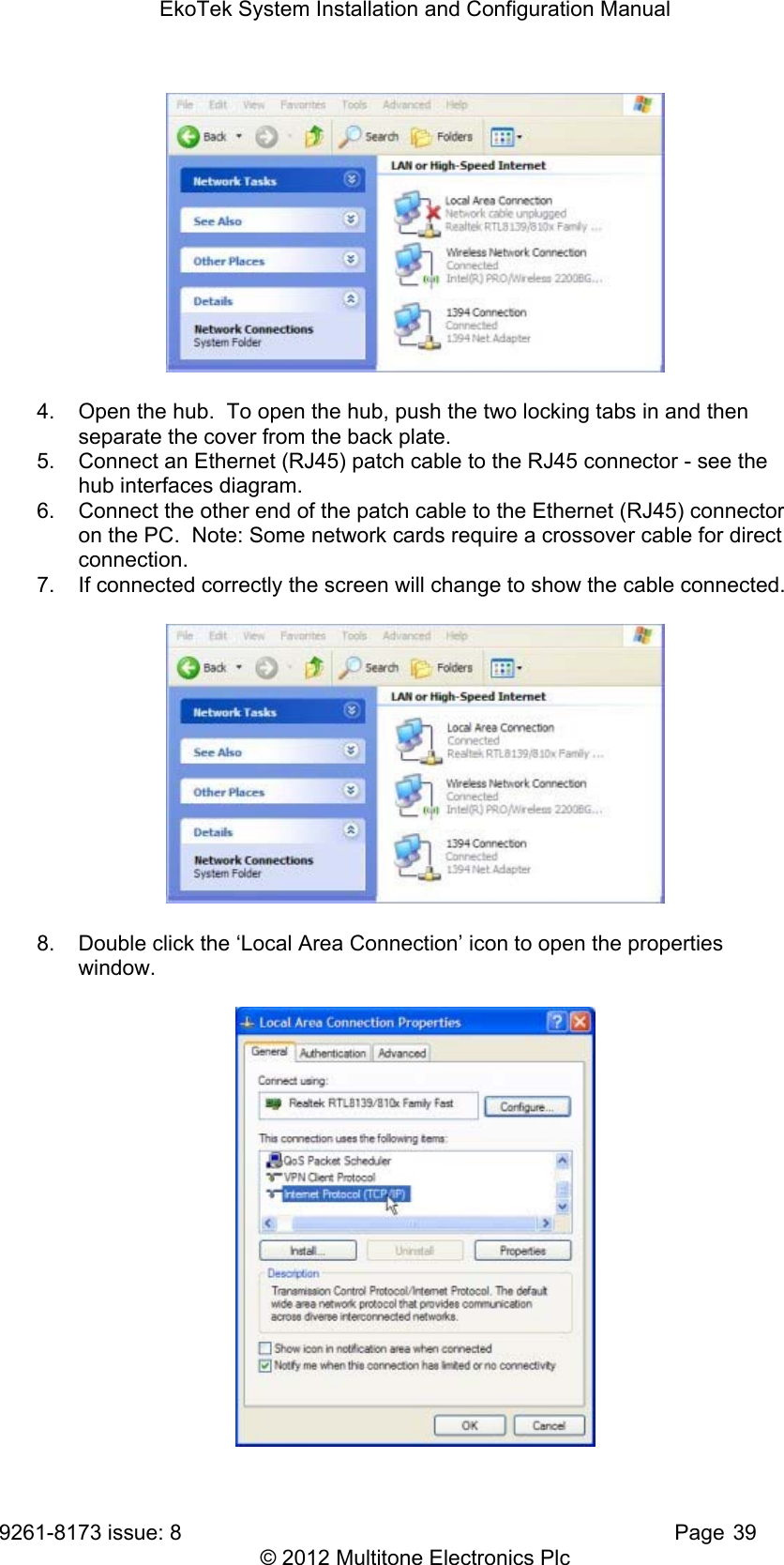
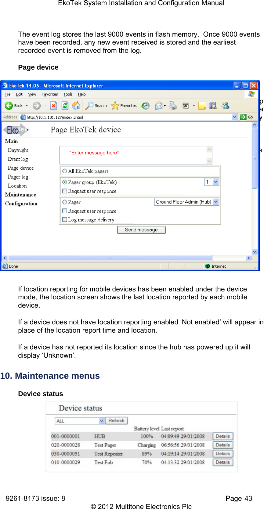
![EkoTek System Installation and Configuration Manual 9261-8173 issue: 8 Page 12 © 2012 Multitone Electronics Plc 1. Disabled. 2. Single press raises alarm. 3. Double press raises alarm. A long press of the red button always clears an alarm raised by the red button or the external alarm contact. The mains powered call point is functionally similar but provides terminals for wiring to an external low voltage DC supply and contains an internal rechargeable battery pack for battery backup in case of supply failure. The call point can also be used as a repeater while still retaining call point functionality. For mounting positions where the unit is at body height this is not recommended, as the quality of link that the call point can offer will degrade when someone stands near or in front of the unit. This may cause devices communicating through the call point repeater to lose contact with the network. For high positions such as operating in conjunction with a ceiling pull cord this should not be a problem. A situation where repeater operation may be acceptable if the unit is at body height is to allow the unit to be a repeater for mobile devices only. This can be achieved by setting the call point’s ‘Downstream channel’ to a channel that other repeaters cannot use as an ‘Upstream channel’. 5. Call fob The call fob allows assistance calls to be raised, using the location signals from repeaters for accurate location determination. The call fob also supports dead man, man down and location alarms [explained in ‘Configuration’ section]. The configuration of the call fob is downloaded from the hub when the call fob is powered up. The selection of the call fob options is by hub configuration. All call fobs are physically identical and support the same features (if enabled at the hub). An LED, buzzer and vibrate motor are contained within the call fob and are used to indicate the call status. These change when a call is accepted by a remote user using the hub or a pager. Indication of ‘assistance on its way’ is signalled in this way. An AAA size battery powers the call fob. Either rechargeable NiMH or disposable alkaline batteries may be used. Note that rechargeable batteries cannot be charged in the call fob; the battery will have to be removed and placed in an external charger when charging is required. For further information see 9621-8277 EkoTek call fob user guide.](https://usermanual.wiki/Multitone-Electronics-PLC/EKOPAG.System-manual/User-Guide-1895899-Page-14.png)

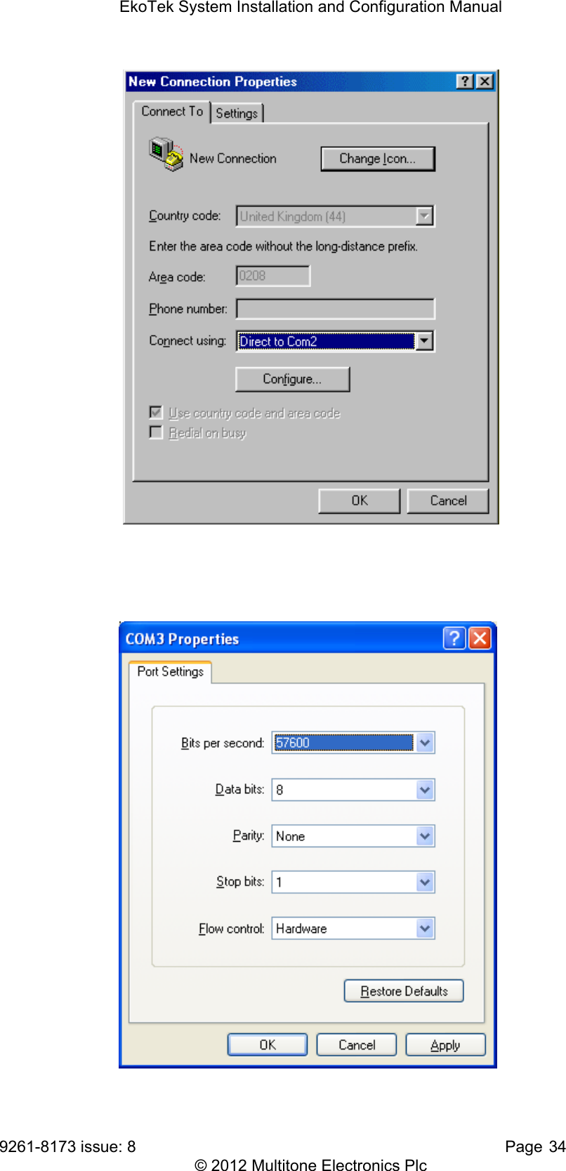
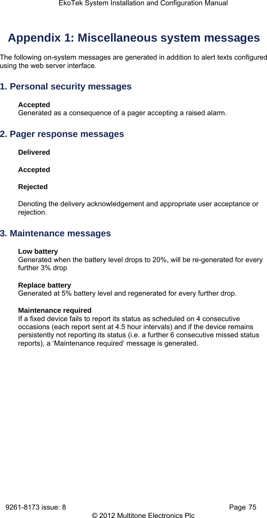
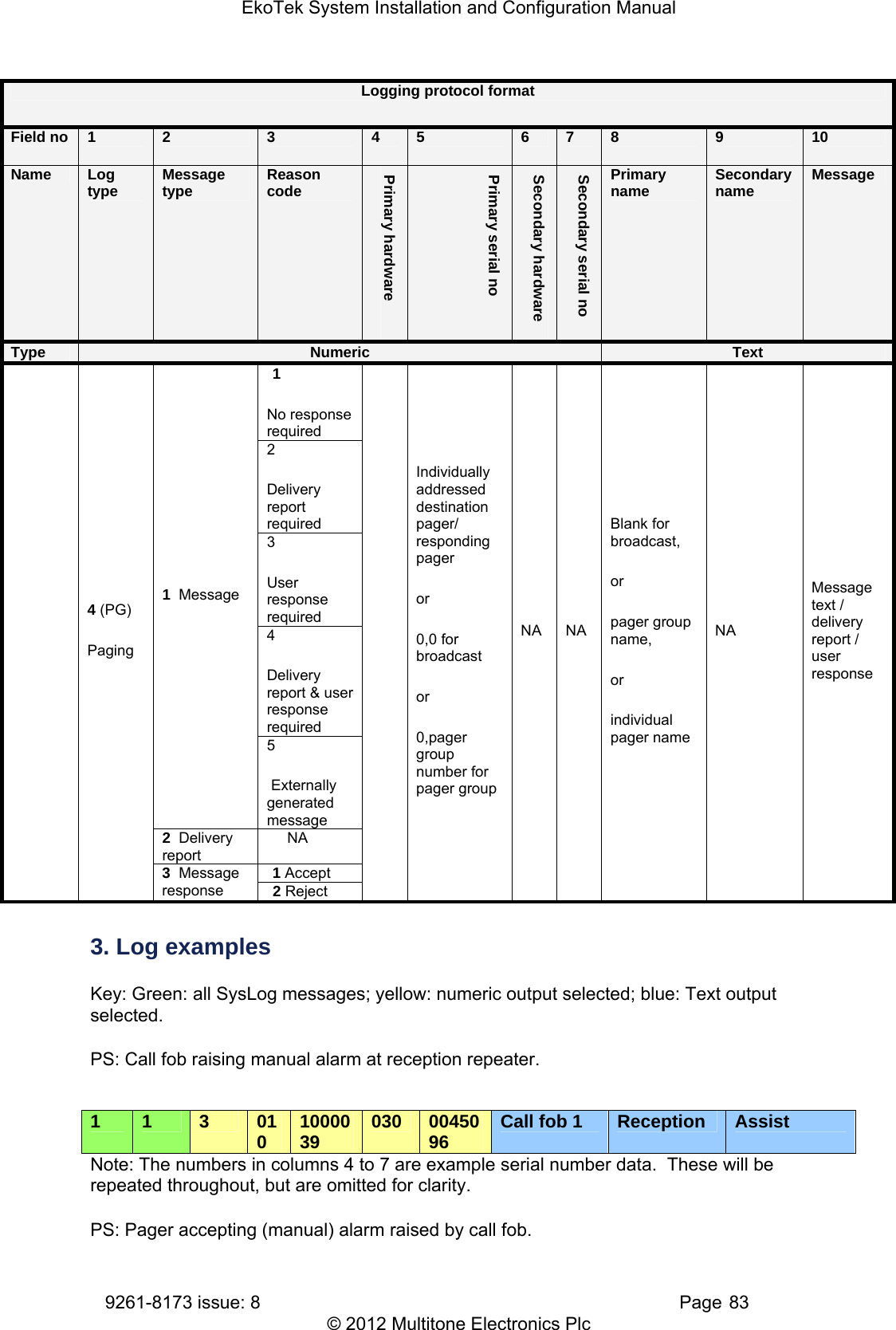
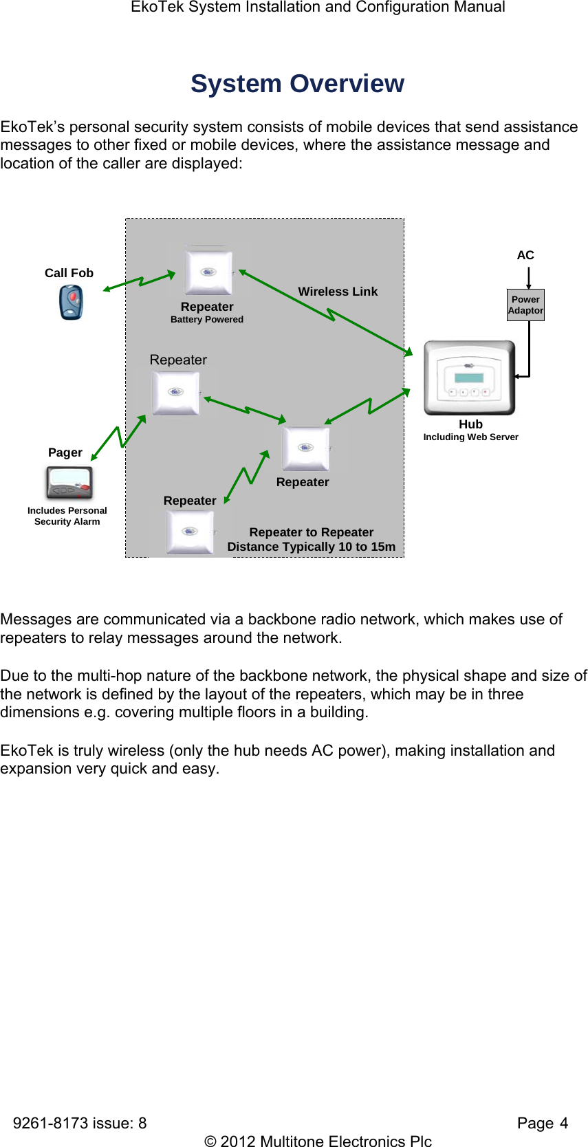
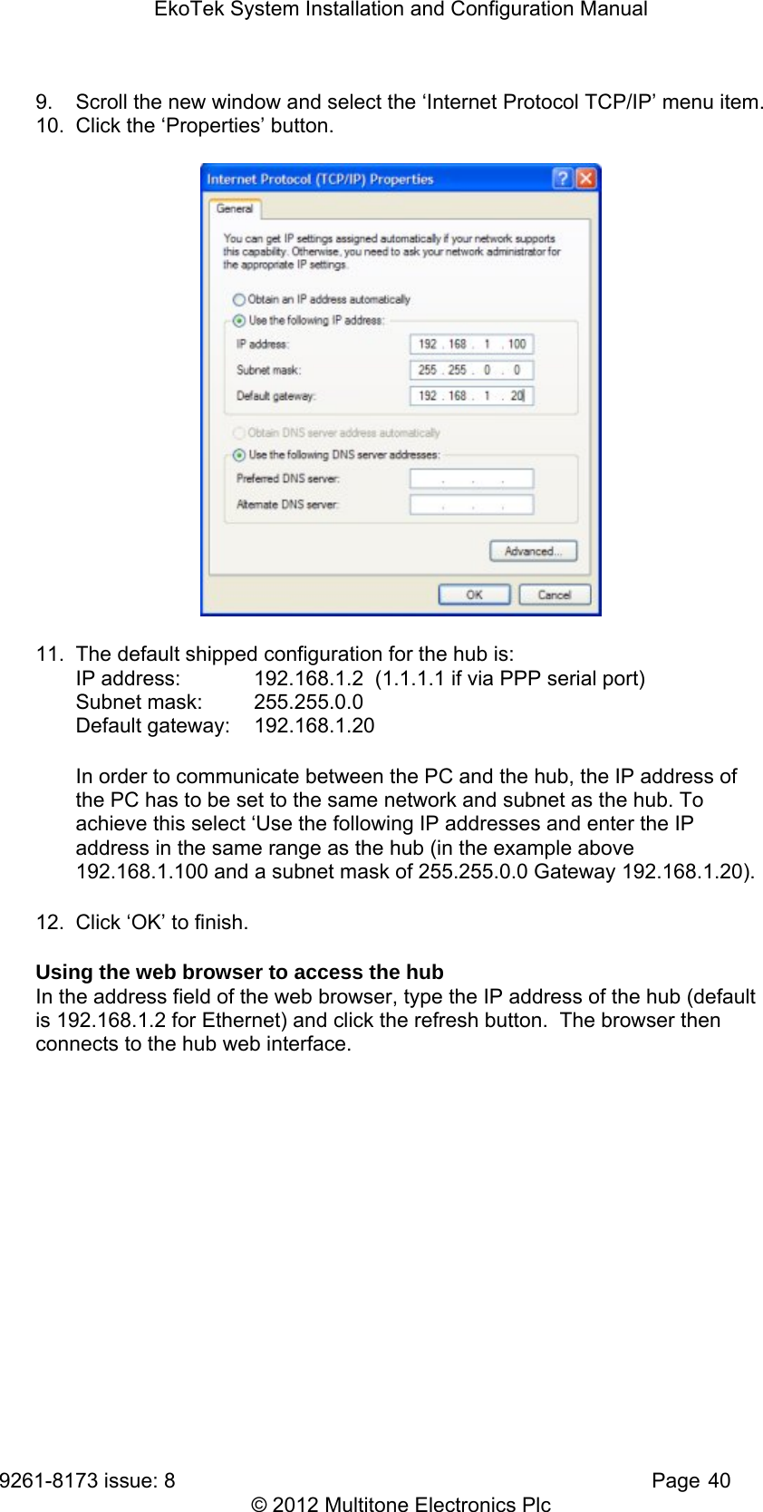
![EkoTek System Installation and Configuration Manual 9261-8173 issue: 8 Page 35 © 2012 Multitone Electronics Plc Configure the port to set the interface speed to 57600 5. Click OK - a blank terminal window will open. You should now be communicating directly between the COM port and modem. Type 'AT' [enter] If you are communicating, the modem will reply with 'OK'. If so, proceed to step 6. If no 'AT' or 'OK' appears, then there is a basic communication issue between the PC and the modem - most likely the COM port selected is incorrect - check this and try again. If problems persist: Check Windows Device Manager (where available) Check that the modem is installed Check the COM port is enabled and has no clashes (indicated by a yellow exclamation mark next to it) Check the COM port is enabled in the system BIOS setup 6. To store the configuration of the port speed in the modem, type 'AT&B2&W' [enter]. You should receive 'OK' as a response. 7. Remove the lead from the PC COM port and connect to Port B on the hub. 8. Close the cover on the hub. Ensure that the ribbon for the keypad is connected to the header on the daughter board, as this is sometimes dislodged when the cover is removed. 9. Test by dialling in to the modem from a PC. The user name and passwords are both ‘EkoTek’. The modem should auto answer and the EkoTek menu screen should be displayed.](https://usermanual.wiki/Multitone-Electronics-PLC/EKOPAG.System-manual/User-Guide-1895899-Page-37.png)
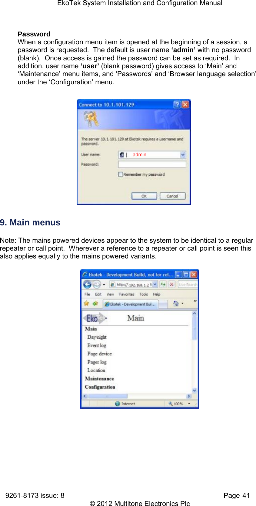
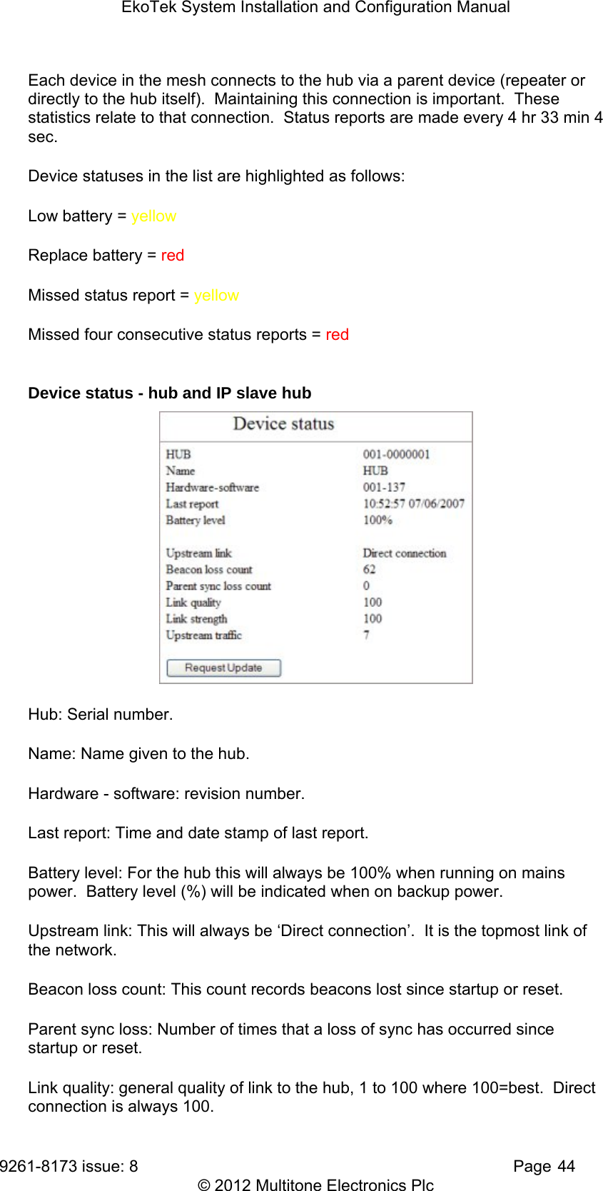
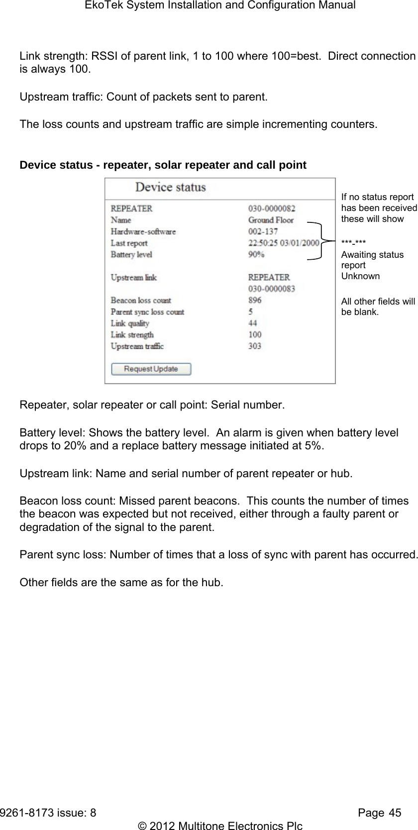
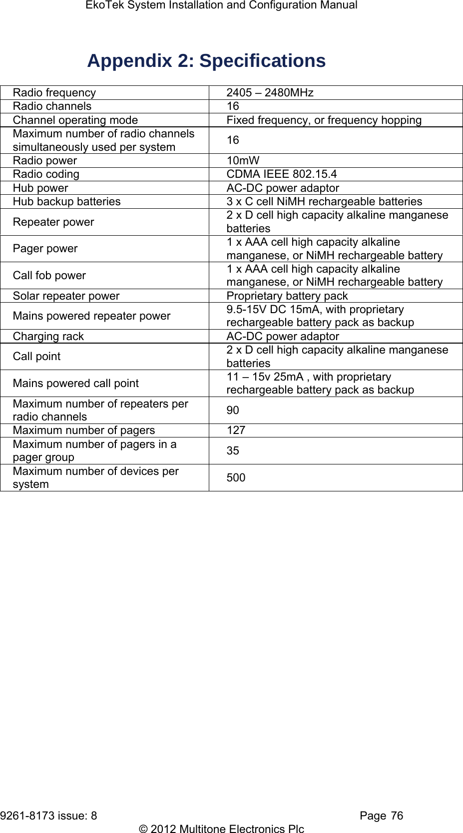
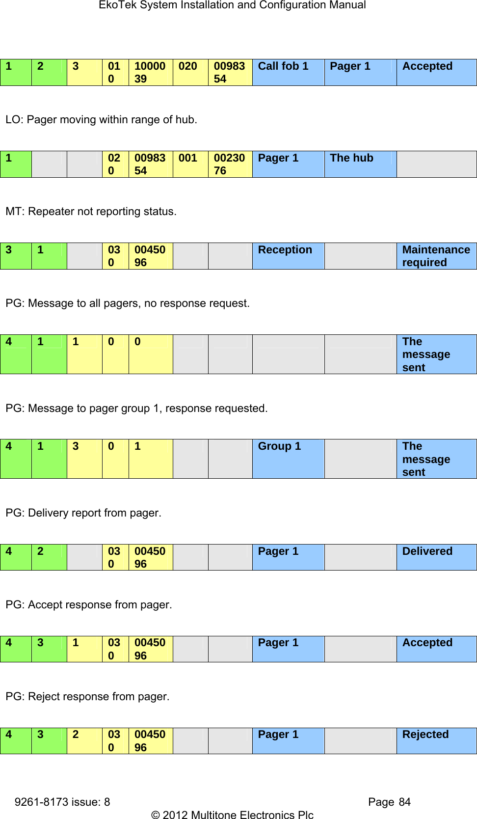
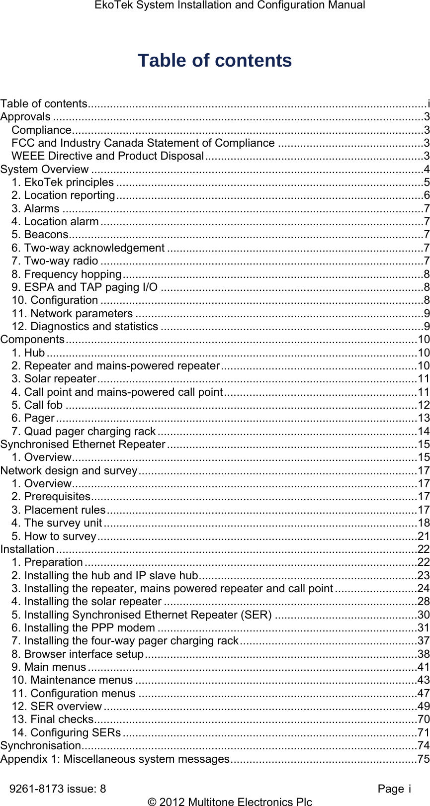
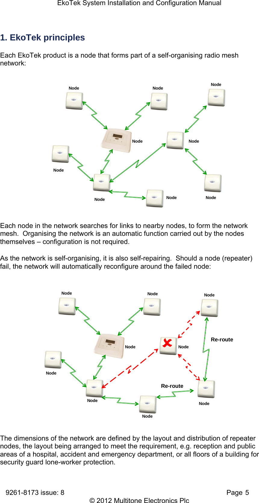
![EkoTek System Installation and Configuration Manual 9261-8173 issue: 8 Page 47 © 2012 Multitone Electronics Plc Tree View The network tree is used to try to provide information relevant to the fixed devices in the system. Information provided includes: Number of times a device requests it’s Config from hub o A high number may indicate the need for additional repeaters – to overcome poor radio connections The RRSI level (as indicated above) o A high number shows a good link but a low number does not necessarily mean a poor link (it is for the last status report only and conditions /parent selections change) The linkage paths between devices o This chain length to a given repeater is the number of ‘I’ symbols in front of it Identifies parent and child relationship The parent can be identified from the child by identifying the (+) and tracking upwards to the (<n>). The number of (I) indicates the number of hops from the hub. This can lead to an unstable network with poor connections. 11. Configuration menus System settings - hub This page sets the network interfaces. It enables configuration of hub settings, clock, external connections and the browser language. Click ‘Configuration’ and select ‘System’. Parent – 030-0005137 Child – 030-0005103 <n> = Number of requests for Config [n] = RSSI Level](https://usermanual.wiki/Multitone-Electronics-PLC/EKOPAG.System-manual/User-Guide-1895899-Page-49.png)