NEC of America 58155N NLite N 5.8 GHz Digital Microwave Radio User Manual LCT
NEC Corporation of America NLite N 5.8 GHz Digital Microwave Radio LCT
UserManual.wiki
>
NEC of America
>
58155N User Manual
>
User Manual - Part V
Contents
1.
User Manual - Part I
2.
User Manual - Part II
3.
User Manual - Part III
4.
User Manual - Part IV
5.
User Manual - Part V
6.
User Manual - Part VI
User Manual - Part V
Navigation menu
Upload a User Manual
Namespaces
Wiki Guide
HTML
PDF
Info
Views
User Manual
Discussion / Help
Navigation

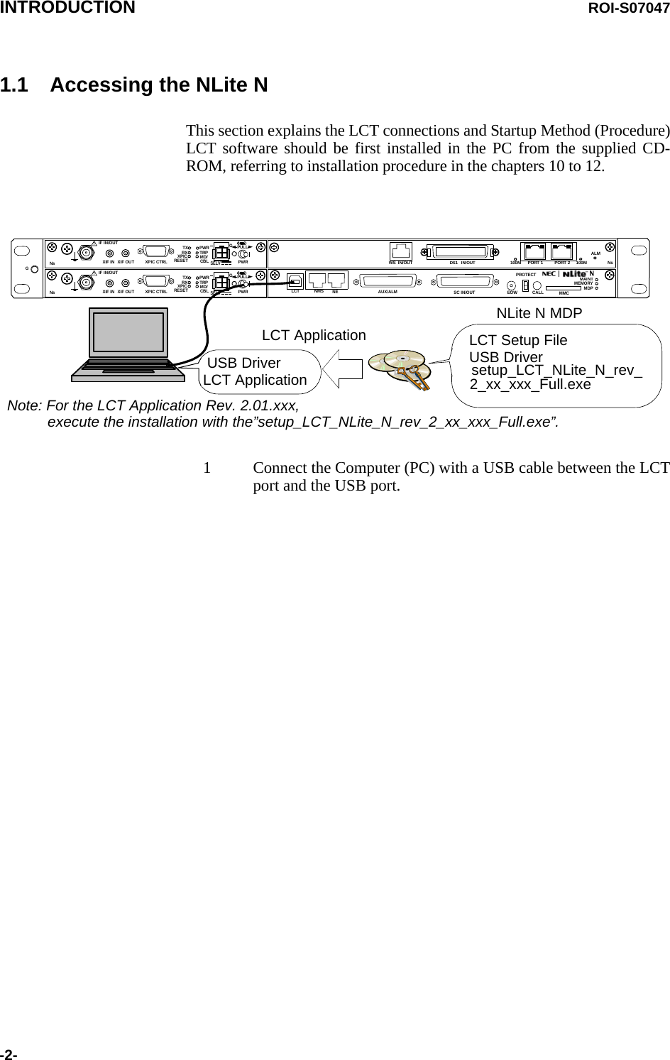
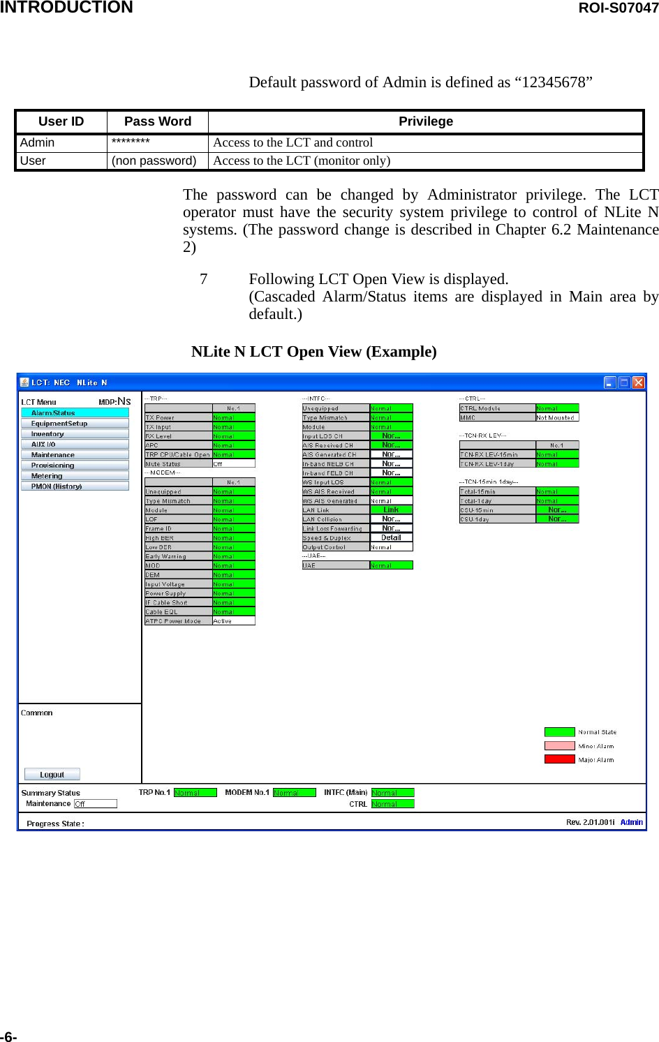
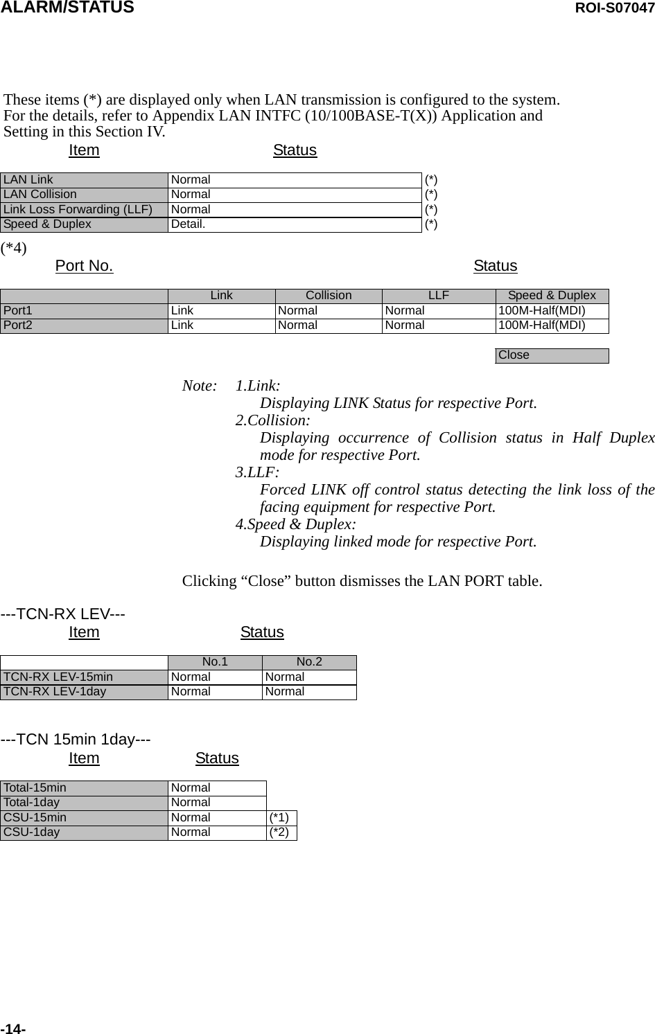
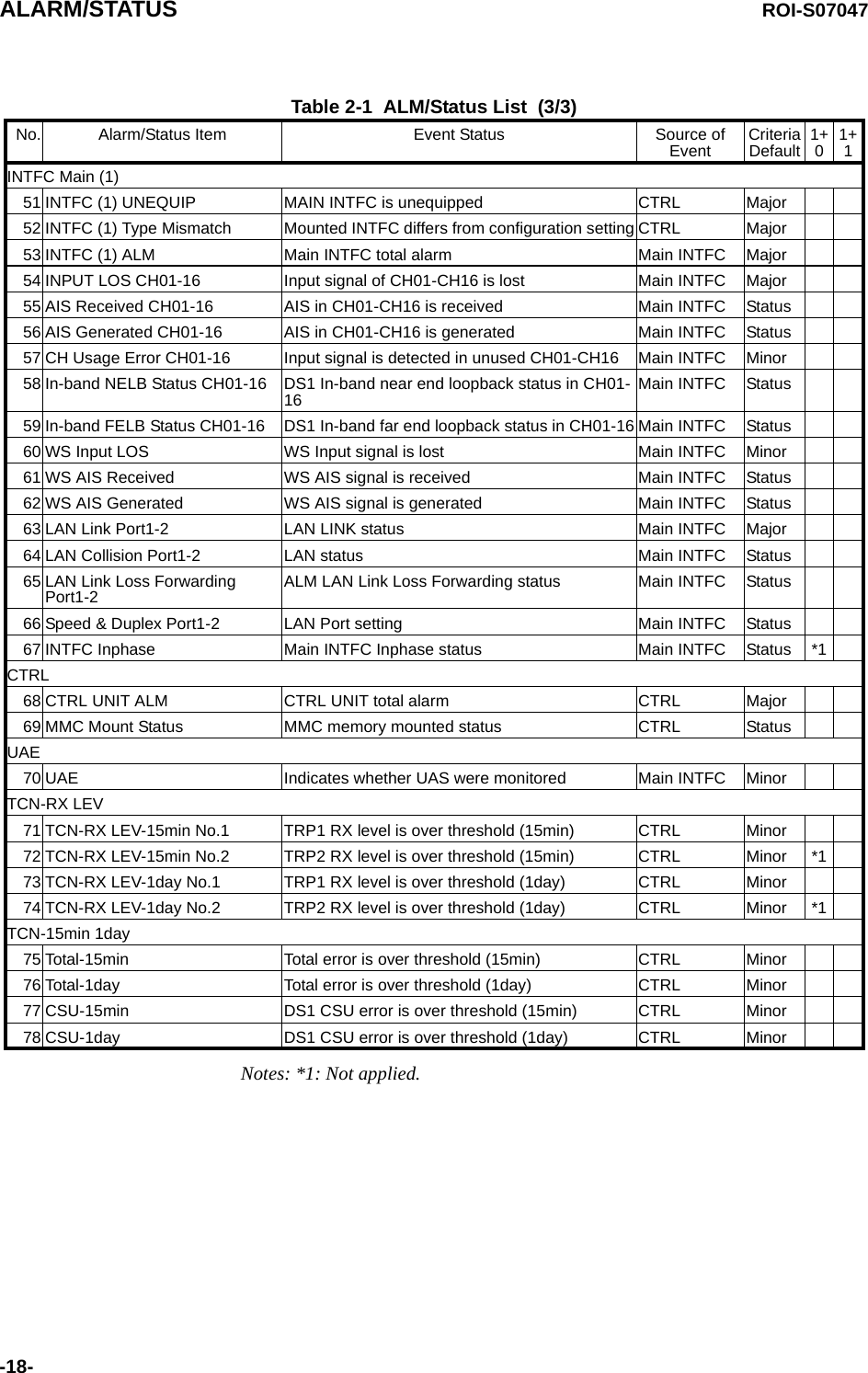
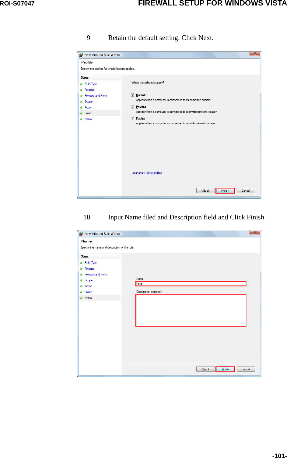
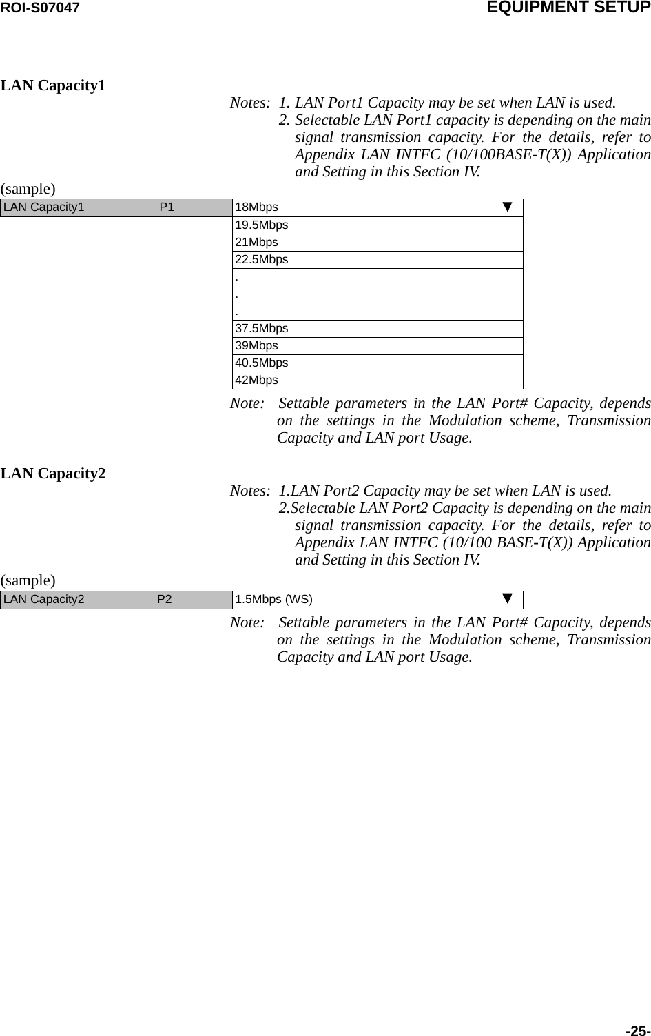
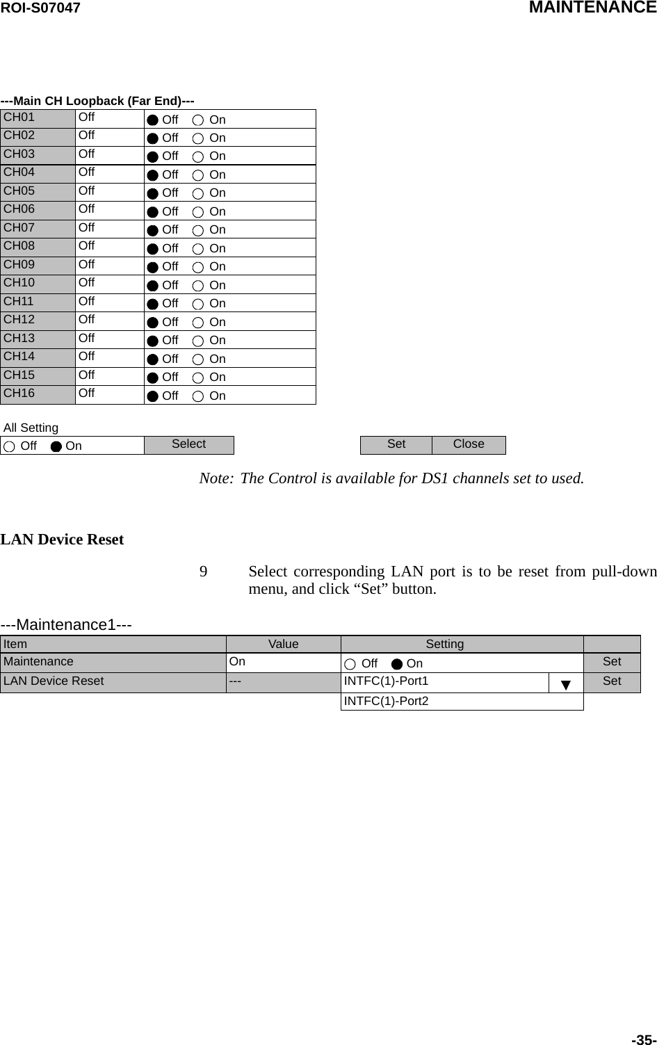
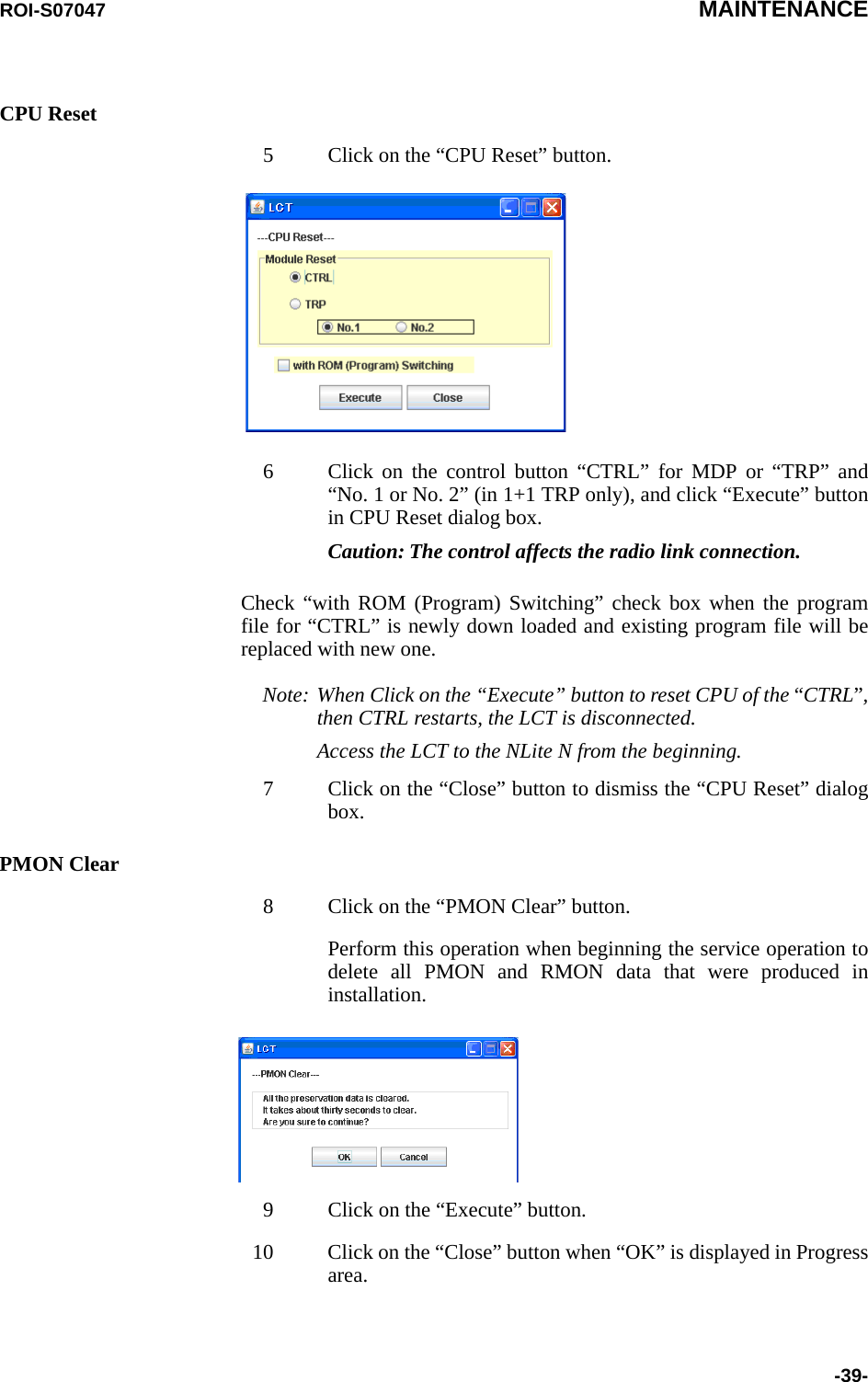
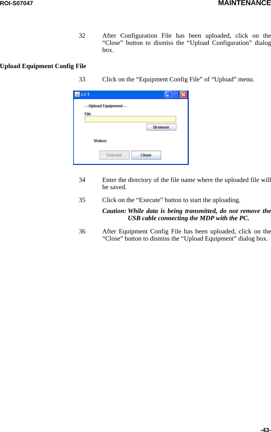
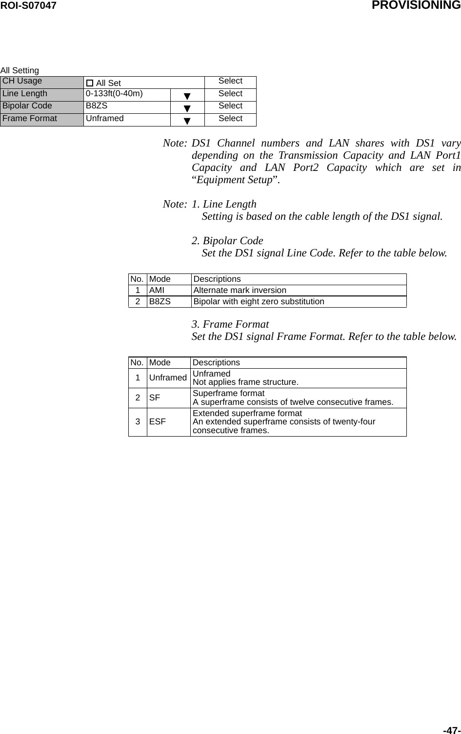
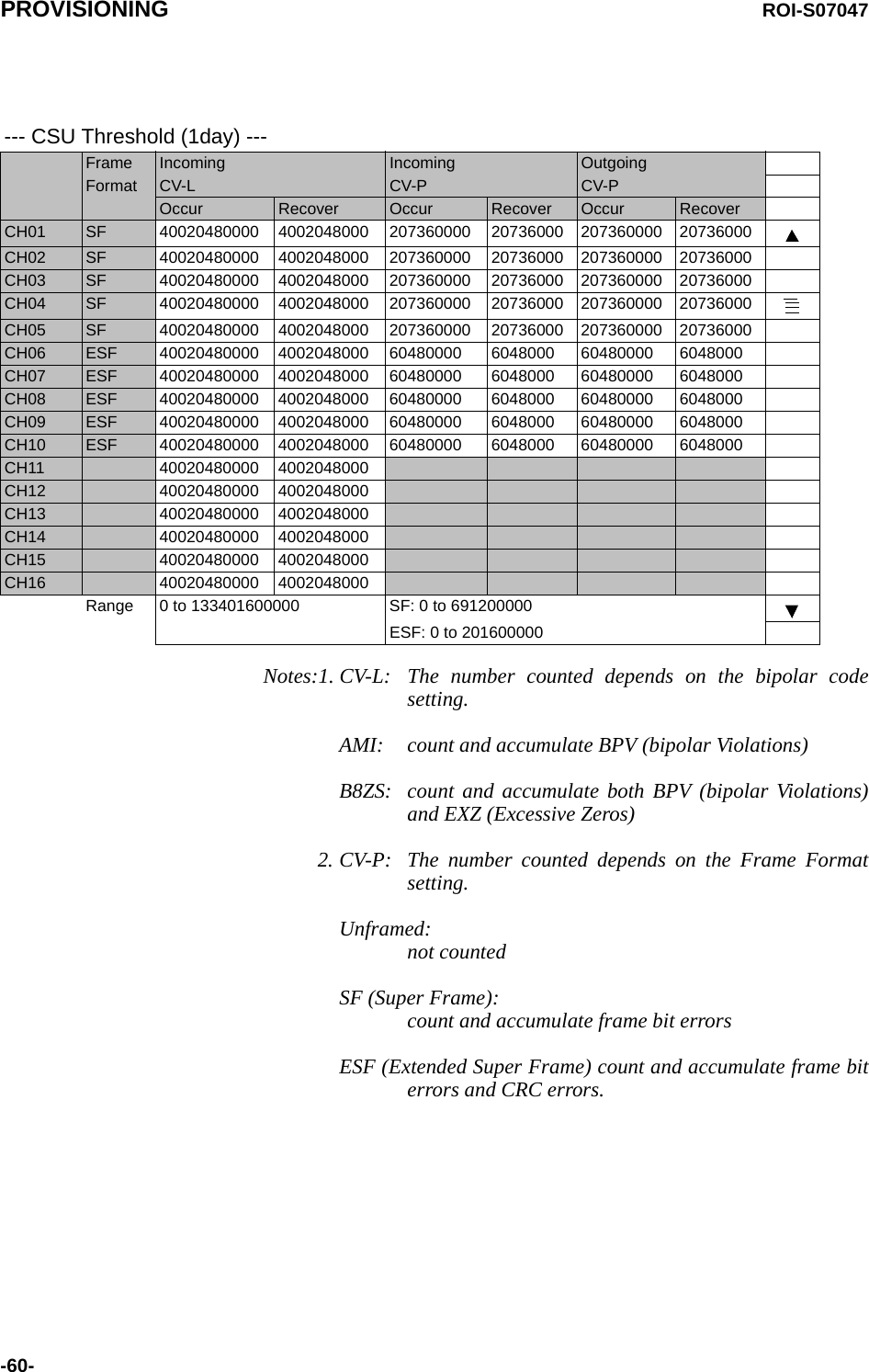
![EQUIPMENT SETUP ROI-S07047-20-3.1 Equipment SetupNote: Click on the “SET” button in Common area after every setting items has been entered.Equipment Setup (Sample)Redundancy Setting 1+1 (Hot Standby Term) Inserted ModuleINTFC Main (WORK) 2Port LAN PKG (e/w DS1) << Main (WORK) 2Port LAN PKG (e/w DS1)INTFC Sub (PROT) Not Used << Sub (PROT) Not UsedXPIC Usage Not UsedAPS Function Unavailable AvailableModulation Scheme QPSKTransmission Capacity 48 [MB]TX RF Frequency [MHz] 0.000RX RF Frequency [MHz] 0.000Frame ID ID1TX Power Control MTPC ATPCTRP Type Split TypeTX SW Type Mute RF SW TypeLAN Port Usage P1-2 Separated (Main+SC)LAN Capacity1 P1 24MbpsLAN Capacity2 P2 64kbps--- TRP FREQ INFO ---TX Start Frequency [MHz] 0.000TX Stop Frequency [MHz] 0.000RX Start Frequency [MHz] 0.000RX Stop Frequency [MHz] 0.000Frequency Step [MHz] 0.000Shift Frequency [MHz] 0.000Upper/Lower UpperSub BandRF Frequency Type TX/RX](https://usermanual.wiki/NEC-of-America/58155N.User-Manual-Part-V/User-Guide-1263945-Page-22.png)
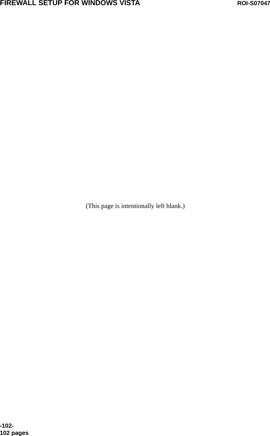
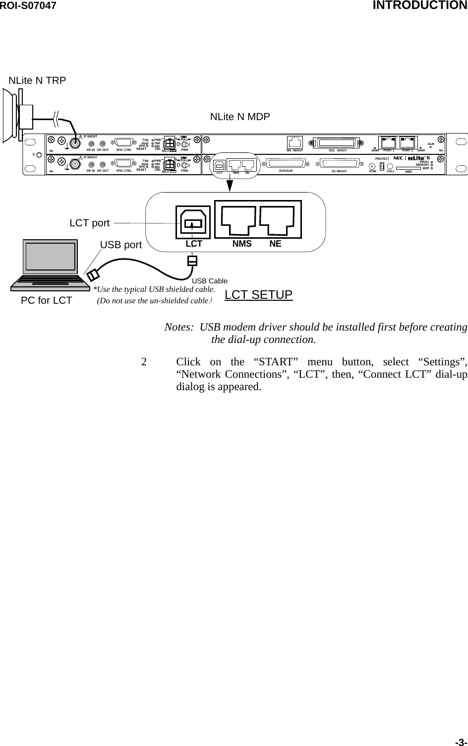
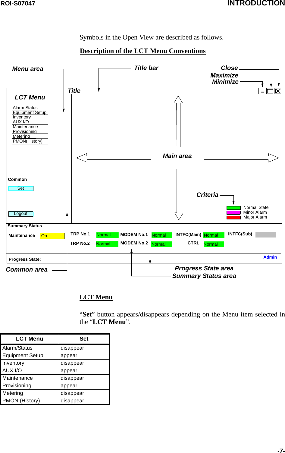
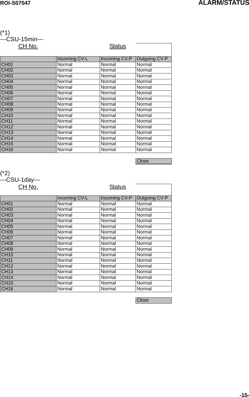
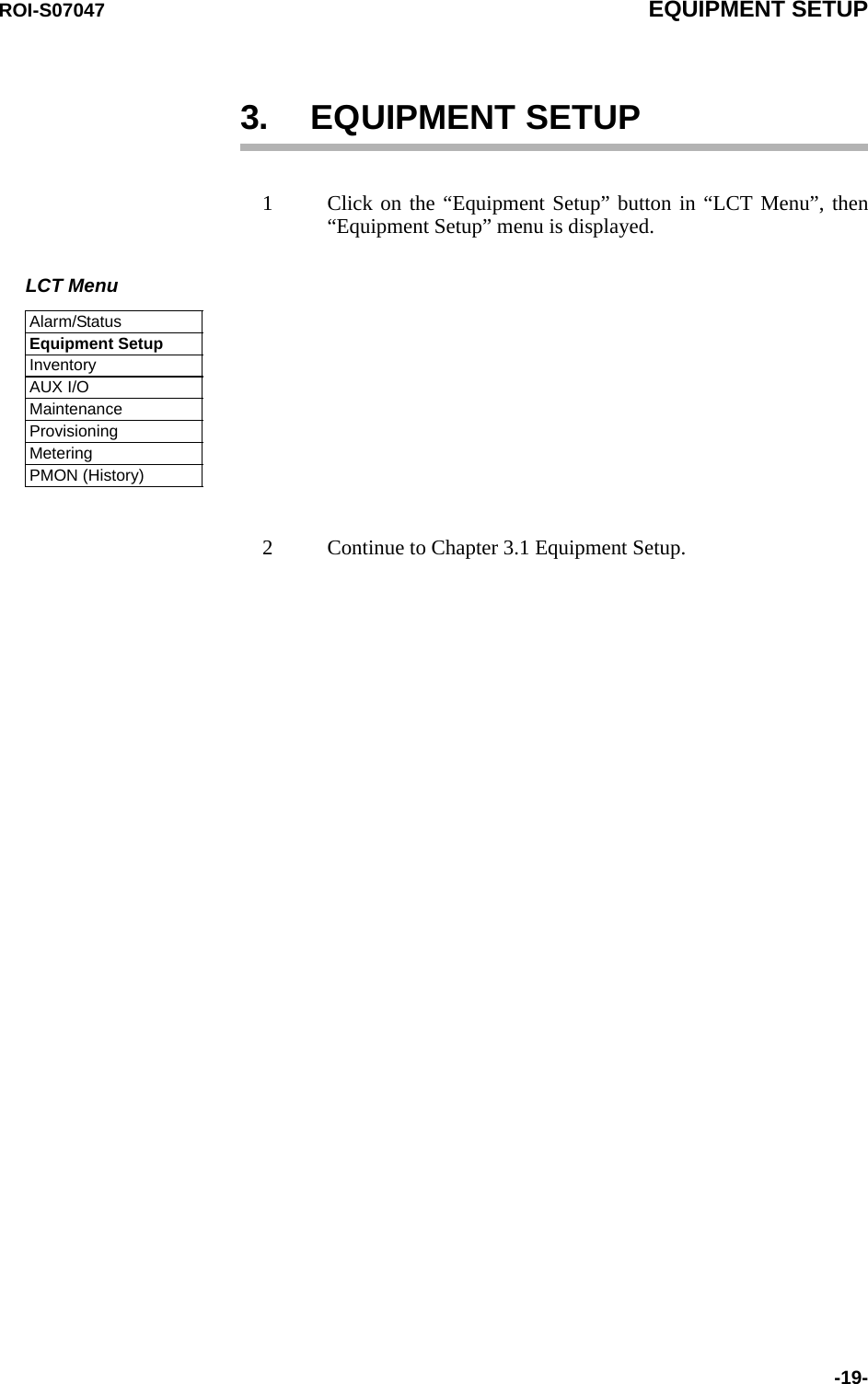
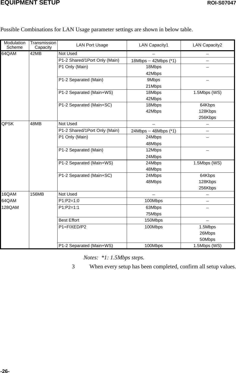
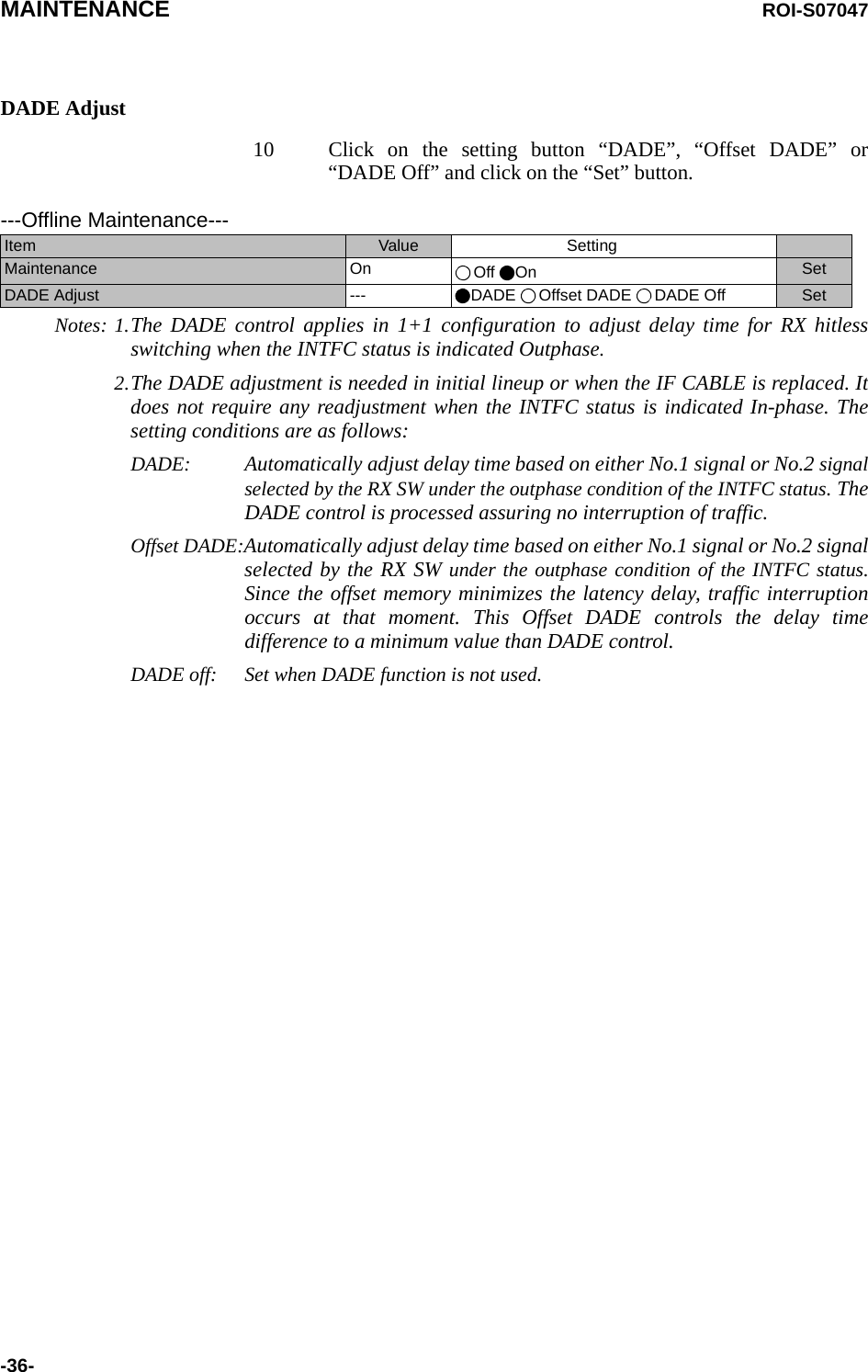
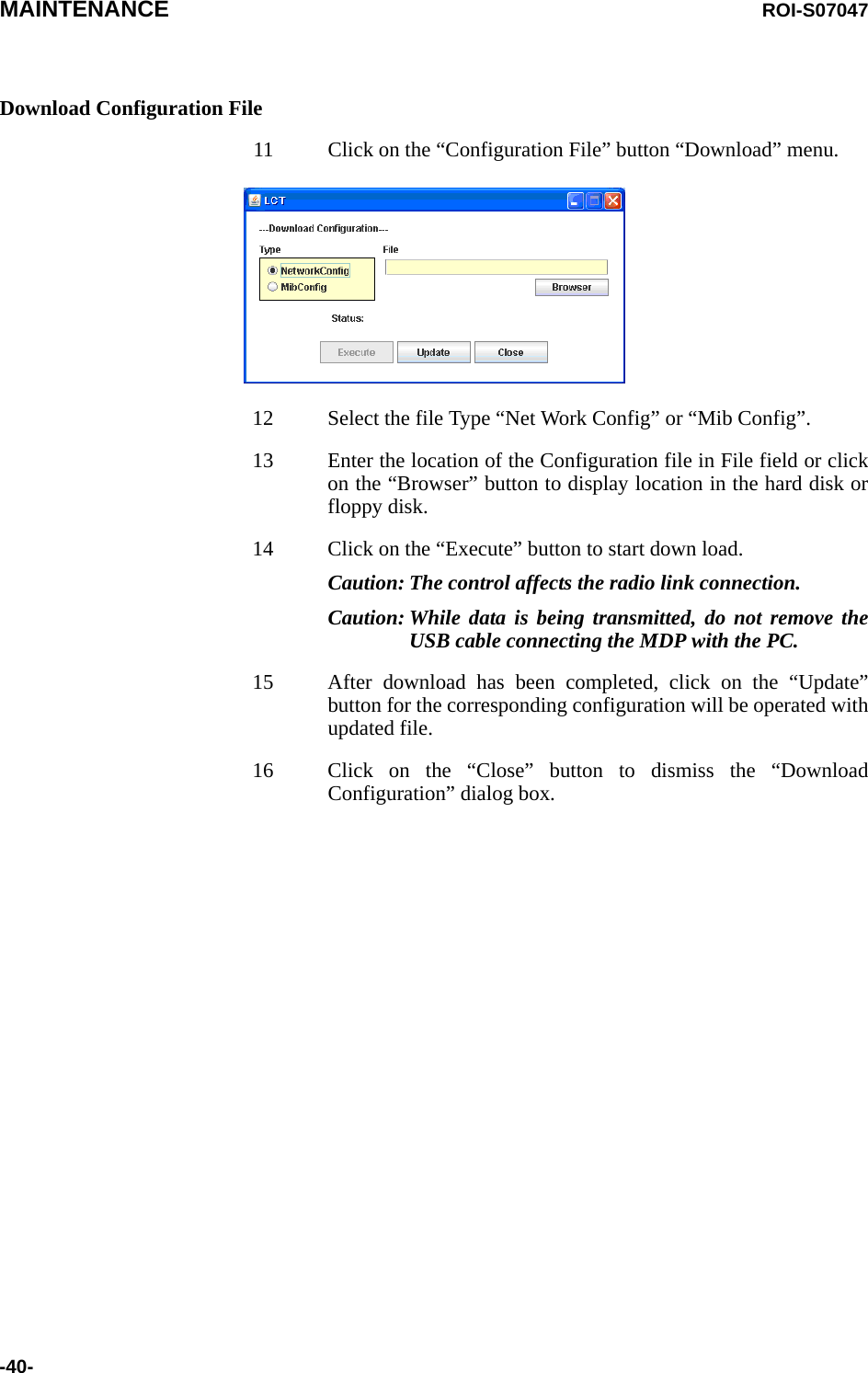
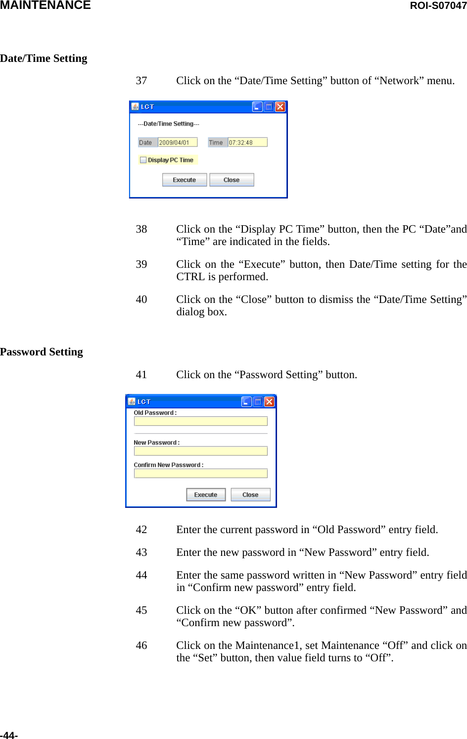
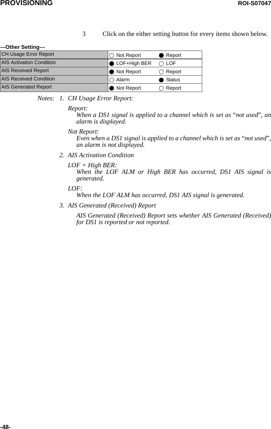
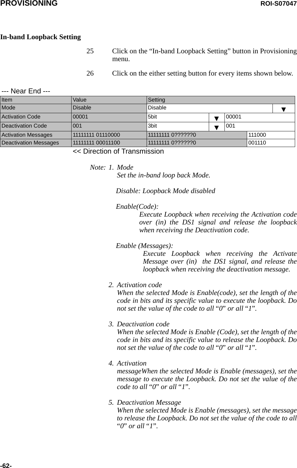
![EQUIPMENT SETUP ROI-S07047-22-Transmission CapacityFor QPSK Modulation Scheme, following pull-down menu is displayed.For 16QAM Modulation Scheme, following pull-down menu is displayed.For 64QAM Modulation Scheme, following menu is displayed.For 128QAM Modulation Scheme, following menu is displayed.Note: Select appropriate Modulation Scheme from pull-down menu forthe required transmission capacity from table below.Transmission Capacity 48 [MB]Transmission Capacity 156 [MB]Transmission Capacity 42 [MB]156 [MB]Transmission Capacity 156 [MB]RF CH Separation Modulation SchemeQPSK 16QAM 64QAM 128QAM10MHz −−42 MB −30MHz −− −156 MB40MHz 48 MB −156 MB −50MHz −156 MB −−](https://usermanual.wiki/NEC-of-America/58155N.User-Manual-Part-V/User-Guide-1263945-Page-24.png)
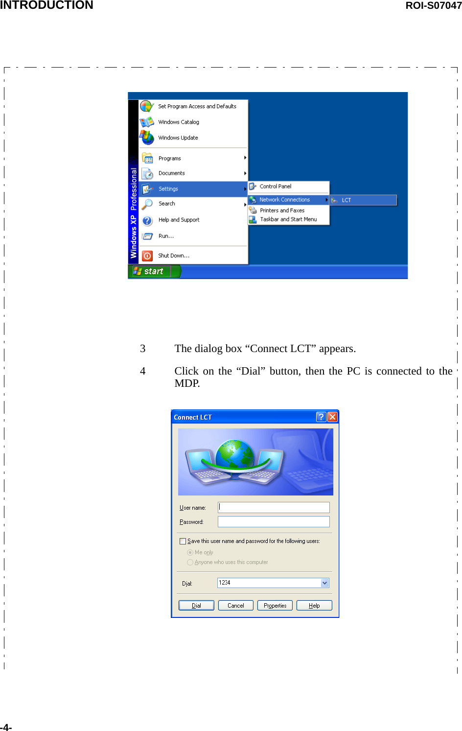
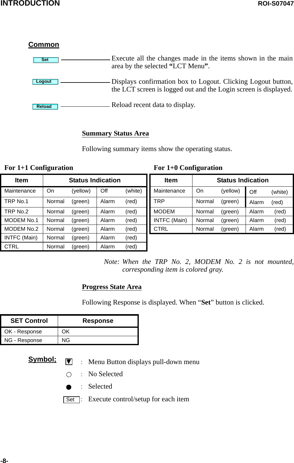
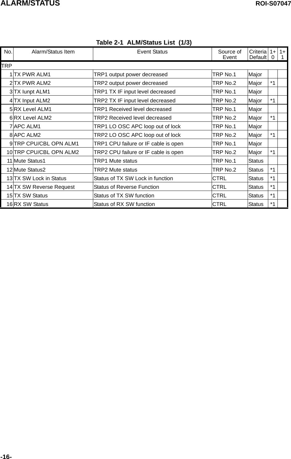
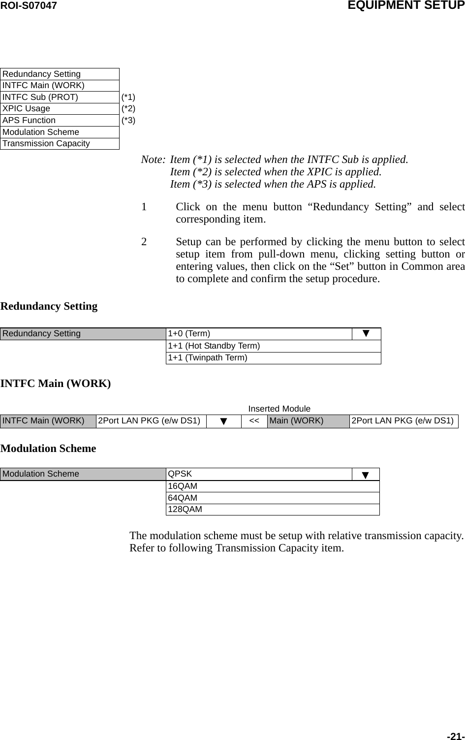
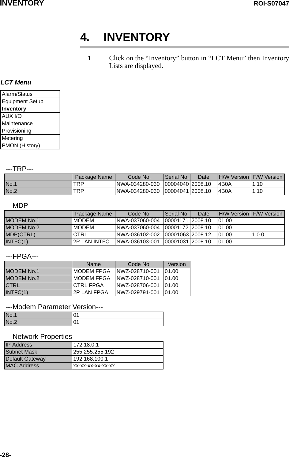
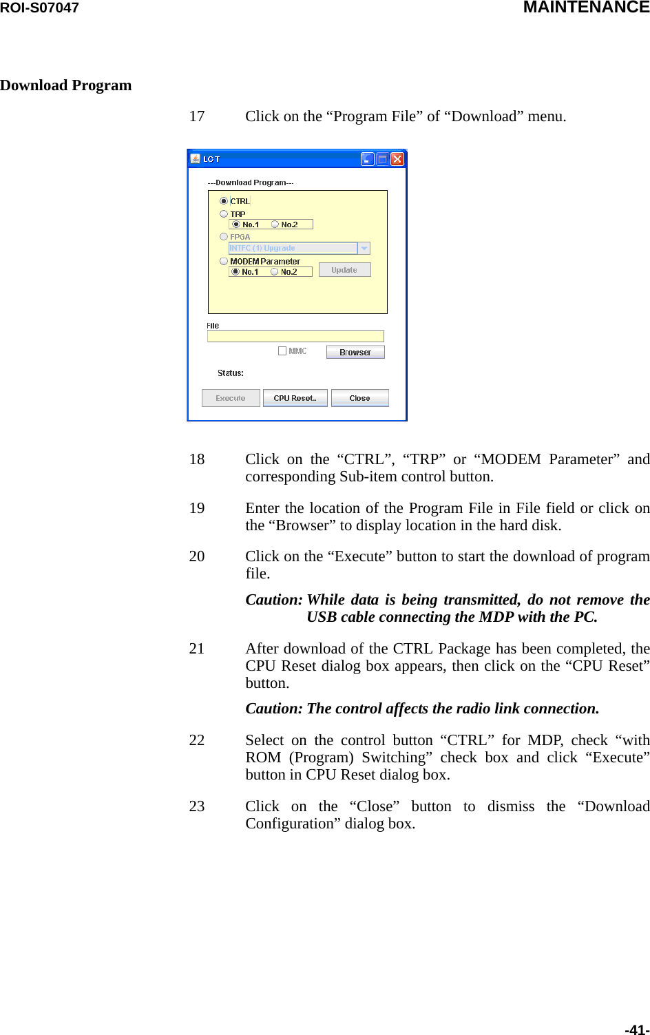
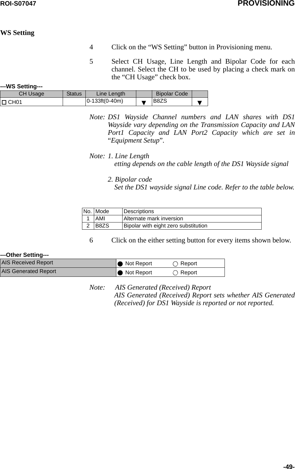
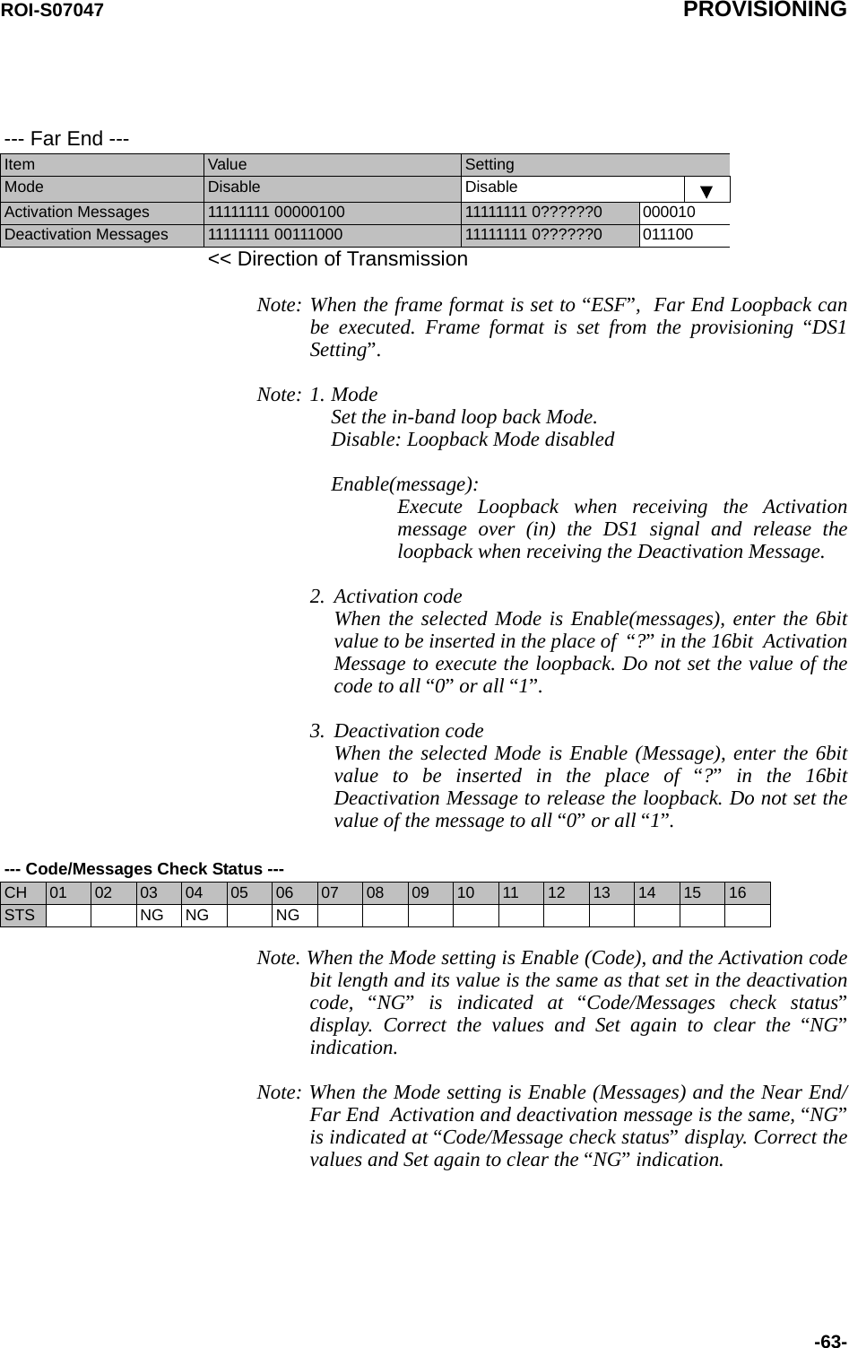
![ROI-S07047 EQUIPMENT SETUP-23-TX Frequency and RF Frequency for No.1 and No.2 are displayed inTwinpath configuration.RF FrequencyNotes: 1. Set different values for No.1 TX frequency and No.2 TXfrequency in the Twinpath configuration.2. Depending on the TRP type, there are two modes for the RFfrequency setup.1. When the transmitting frequency is set, the receivingfrequency is automatically assigned. 2. When the transmitting frequency is set, the receivingfrequency is automatically assigned or setting of it inmanual is also available. In this type, change the RFfrequency values which is automatically assigned. The entered TX RF frequency value should be within the Start andStop frequency range of Sub-band which is indicated on the NamePlate of each TRP. For details, refer to the Appendix RADIOFREQUENCY PLAN FOR NLite N in Section 1.Caution: For the 6 GHz band of NHG, the BPF of TX and RX of theTRP are adjusted to each assigned frequency. Then, tochange the RF channel frequency over the variable range,both BPFs replacement and LCT setup are required.Frame IDNote: Click menu button and set the frame ID in order to discriminatethe signal. As a signal with a different ID cannot be received, theID of the opposite station should be set the same. The number ofIDs which can be set up; ID1 through ID 32.TX RF Frequency (No.1) [MHz]TX RF Frequency (No.2) [MHz]RX RF Frequency (No.1) [MHz]RX RF Frequency (No.2) [MHz]Frame ID (No.1)Frame ID (No.2)](https://usermanual.wiki/NEC-of-America/58155N.User-Manual-Part-V/User-Guide-1263945-Page-25.png)
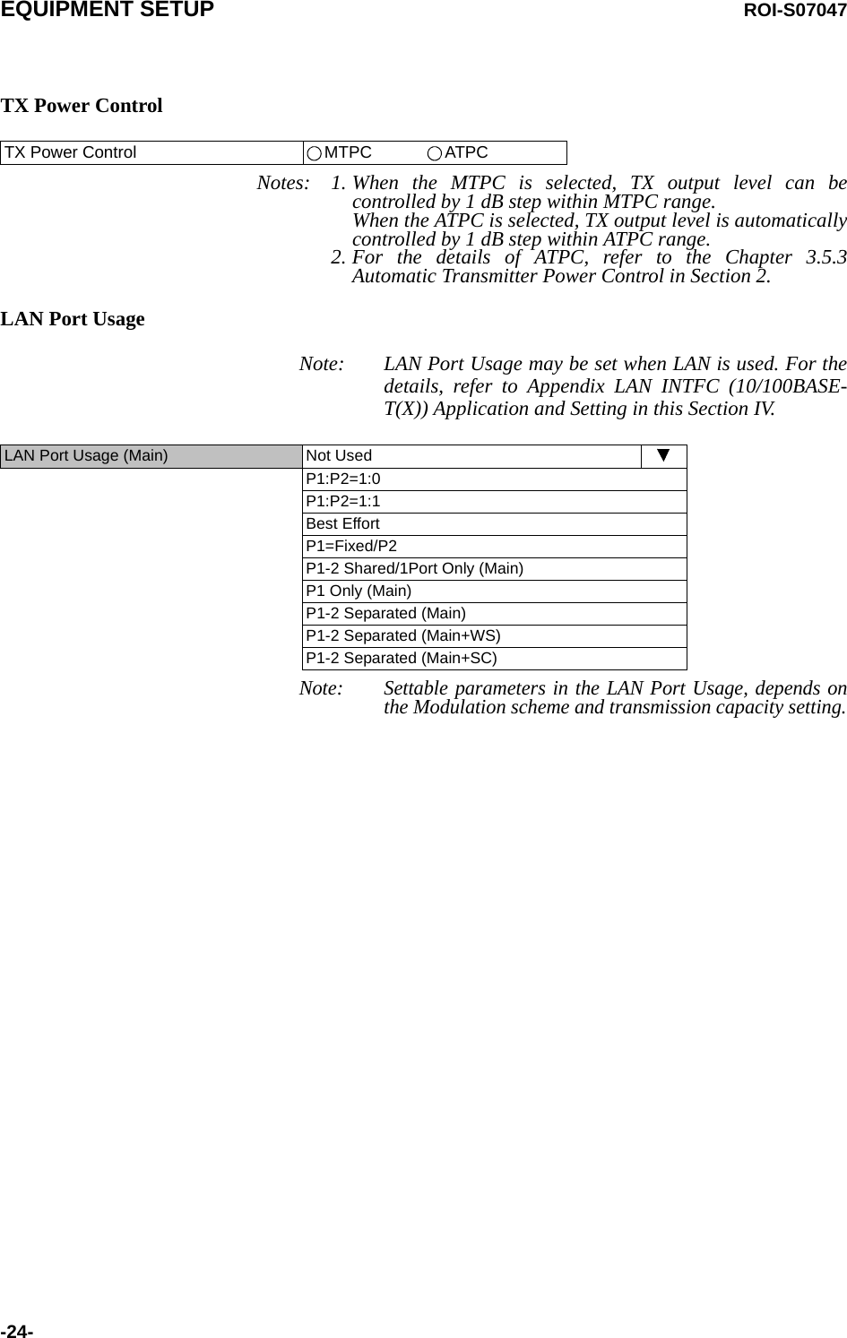
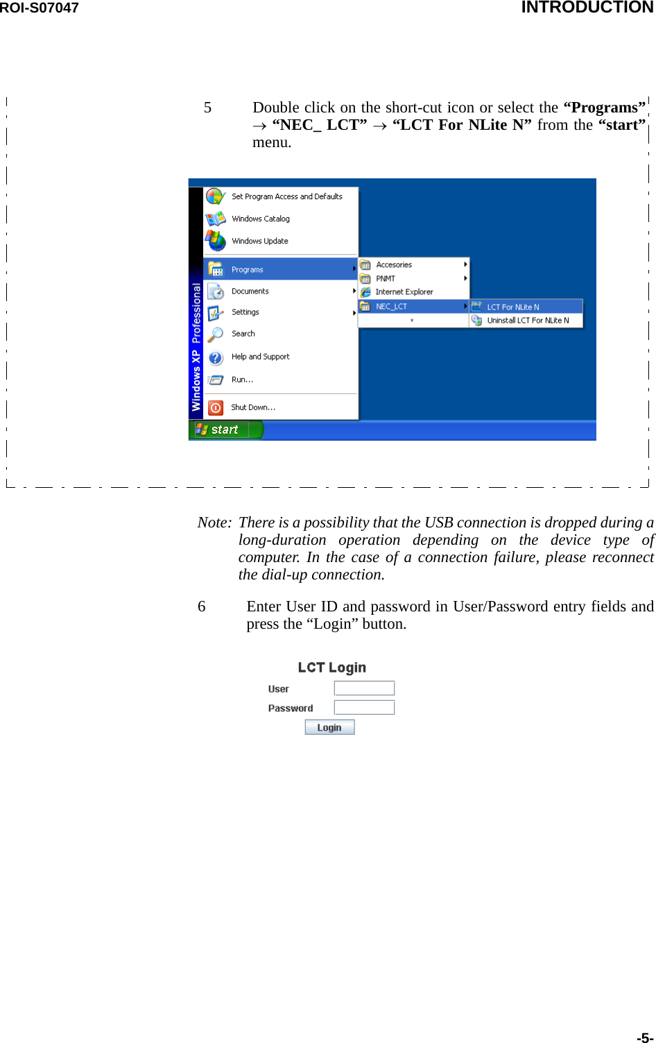
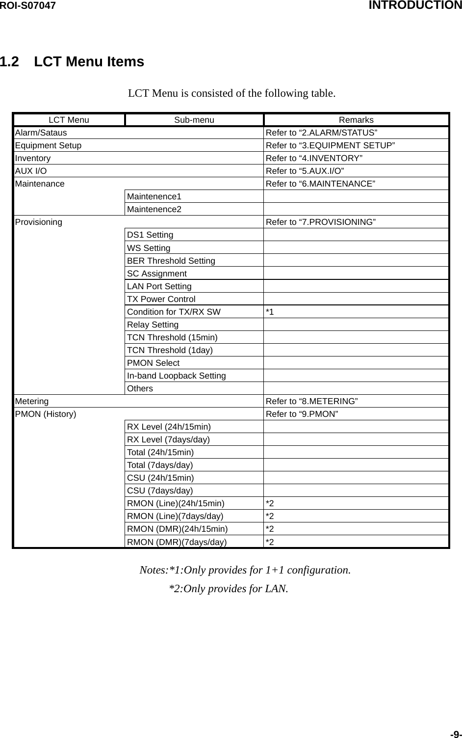
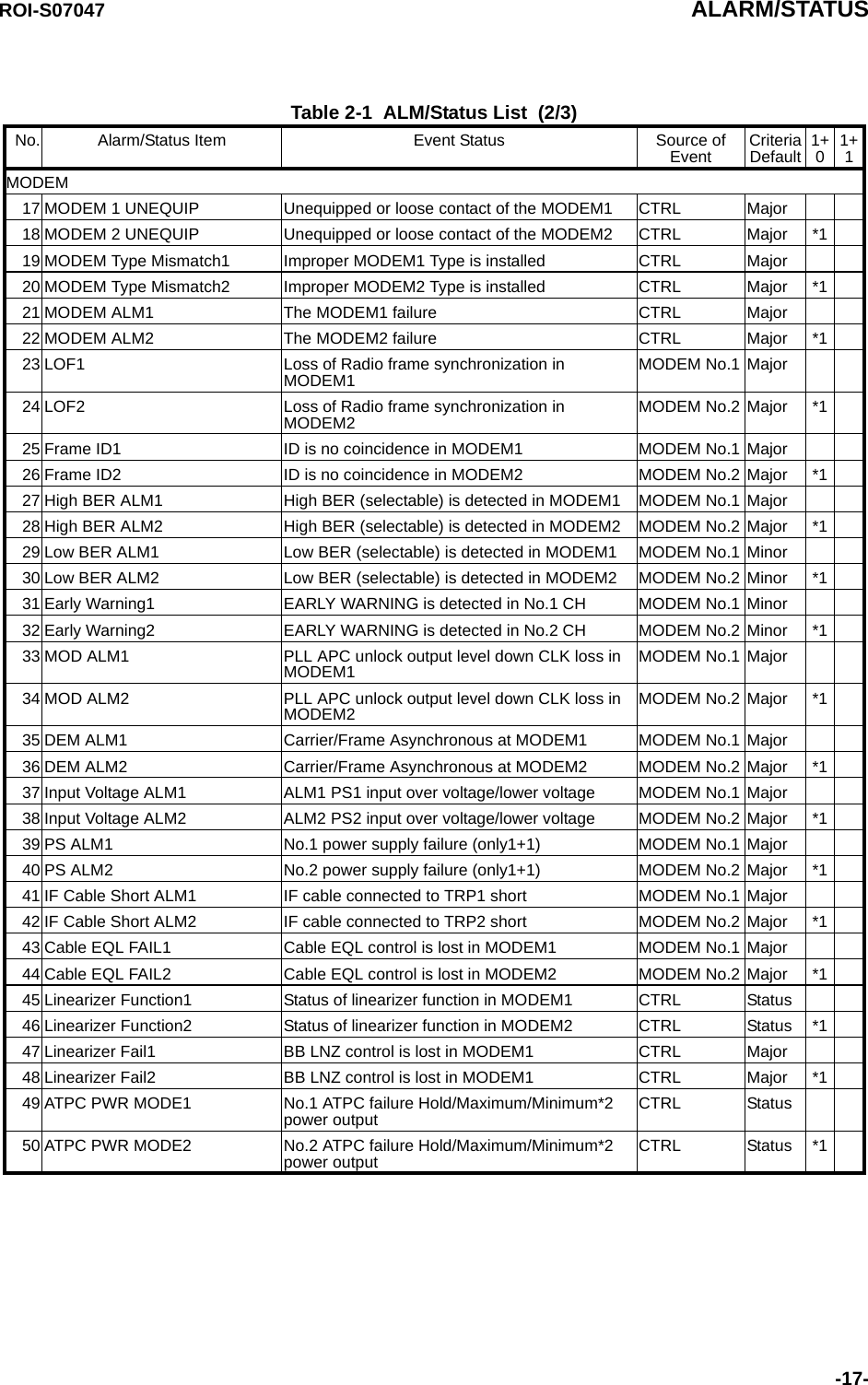
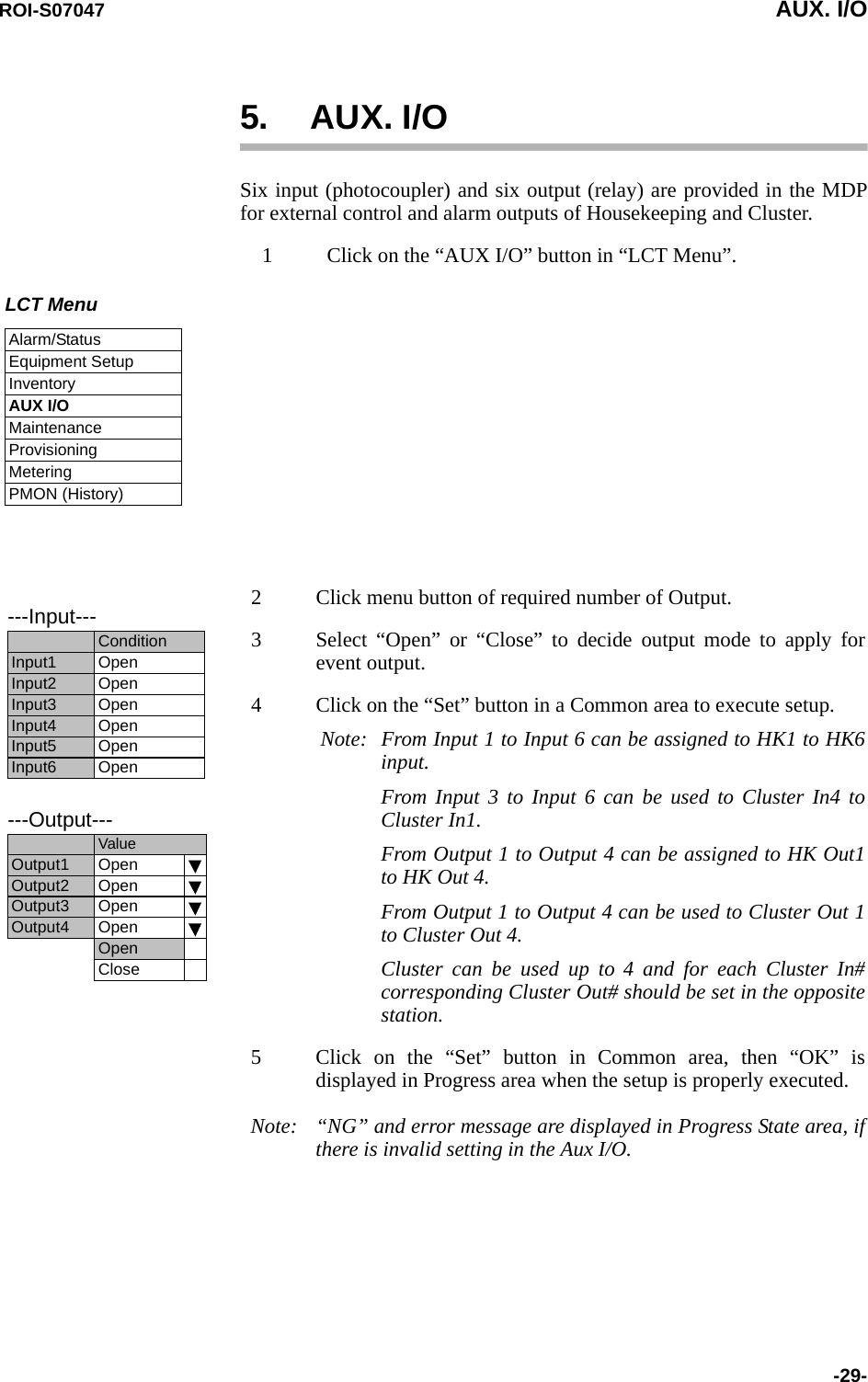
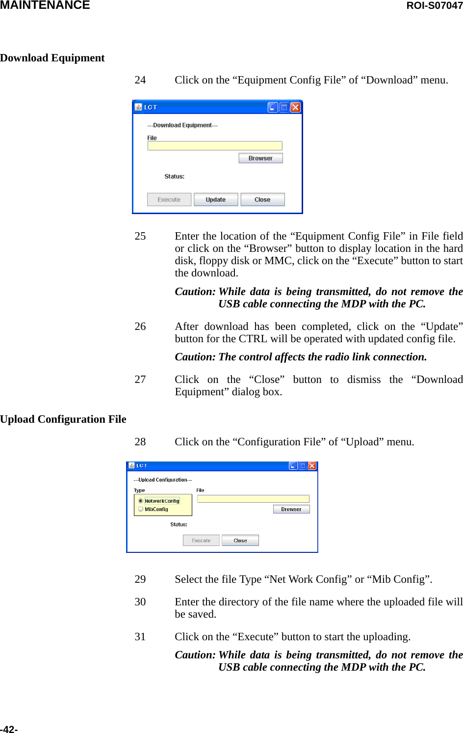
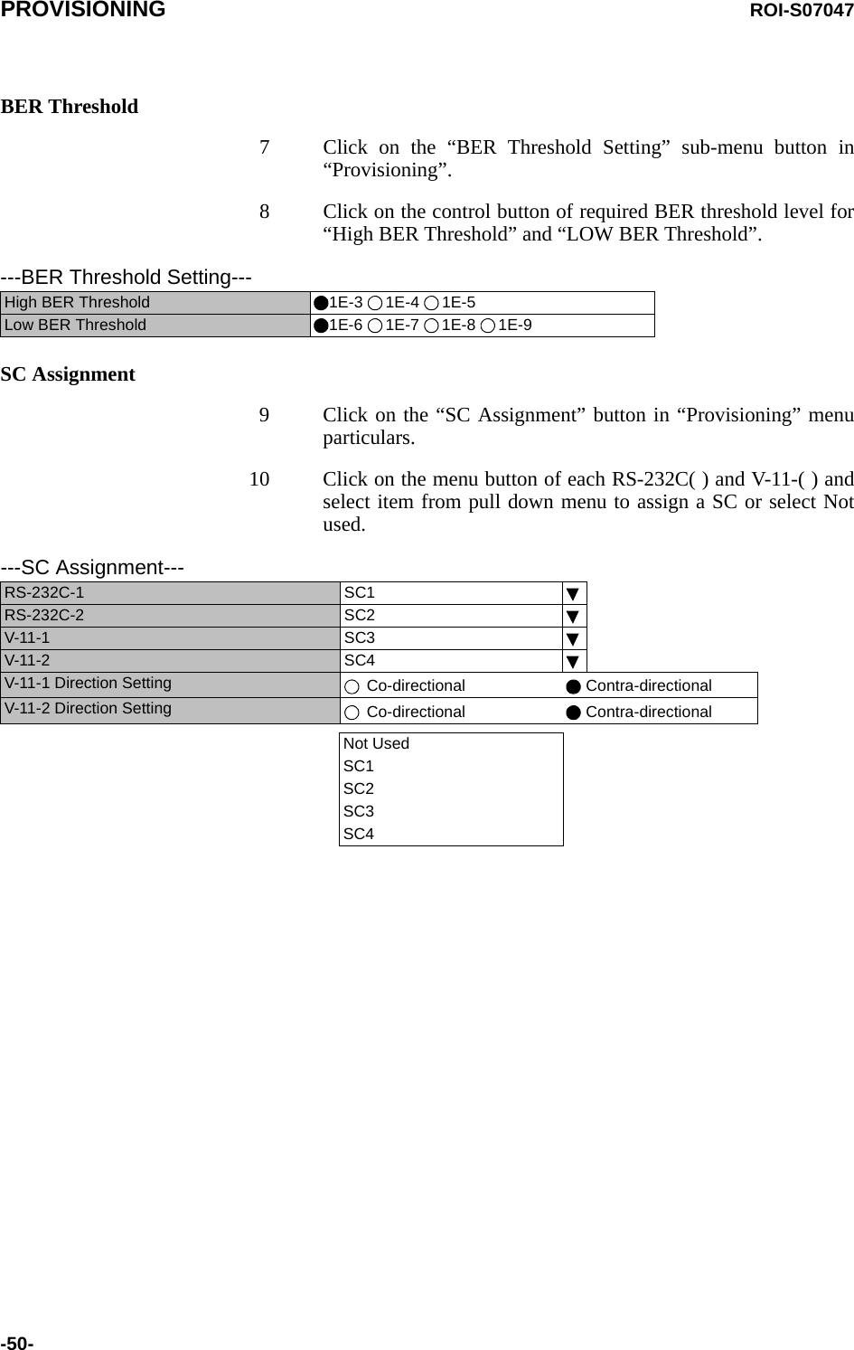
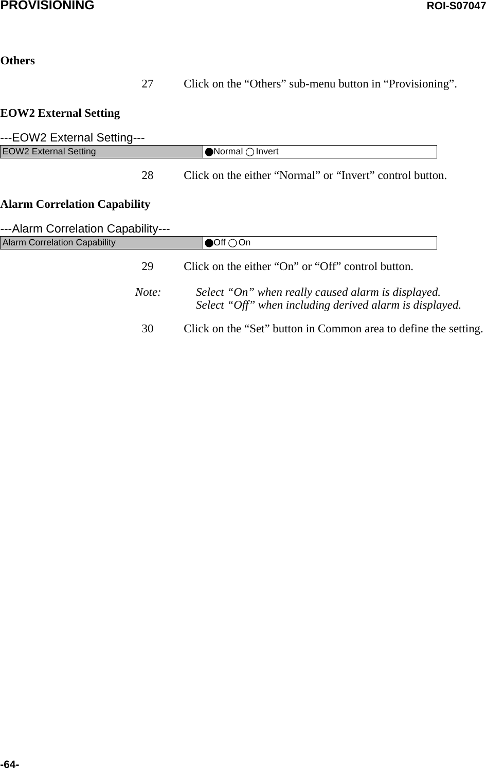
![ROI-S07047 EQUIPMENT SETUP-27-TRP FREQ INFO4 Click on the “Set” button in Common area, then “OK” isdisplayed in Progress area when the setup is properly executed.Note: “NG” and error message are displayed in Progress State area,if there is invalid setting in the Equipment Setup.---TRP FREQ INFO---TX Start Frequency (No.1) [MHz]TX Stop Frequency (No.1) [MHz]Frequency Step (No.1) [MHz]Shift Frequency (No.1) [MHz]Upper/Lower (No.1)Sub Band (No.1)TX Start Frequency (No.2) [MHz]TX Stop Frequency (No.2) [MHz]Frequency Step (No.2) [MHz]Shift Frequency (No.2) [MHz]Upper/Lower (No.2)Sub Band (No.2)](https://usermanual.wiki/NEC-of-America/58155N.User-Manual-Part-V/User-Guide-1263945-Page-29.png)
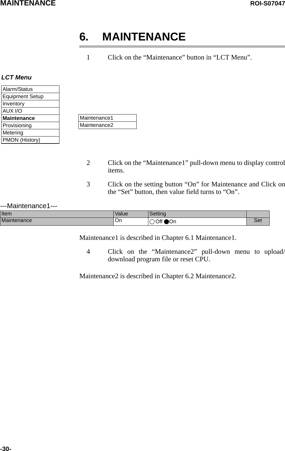
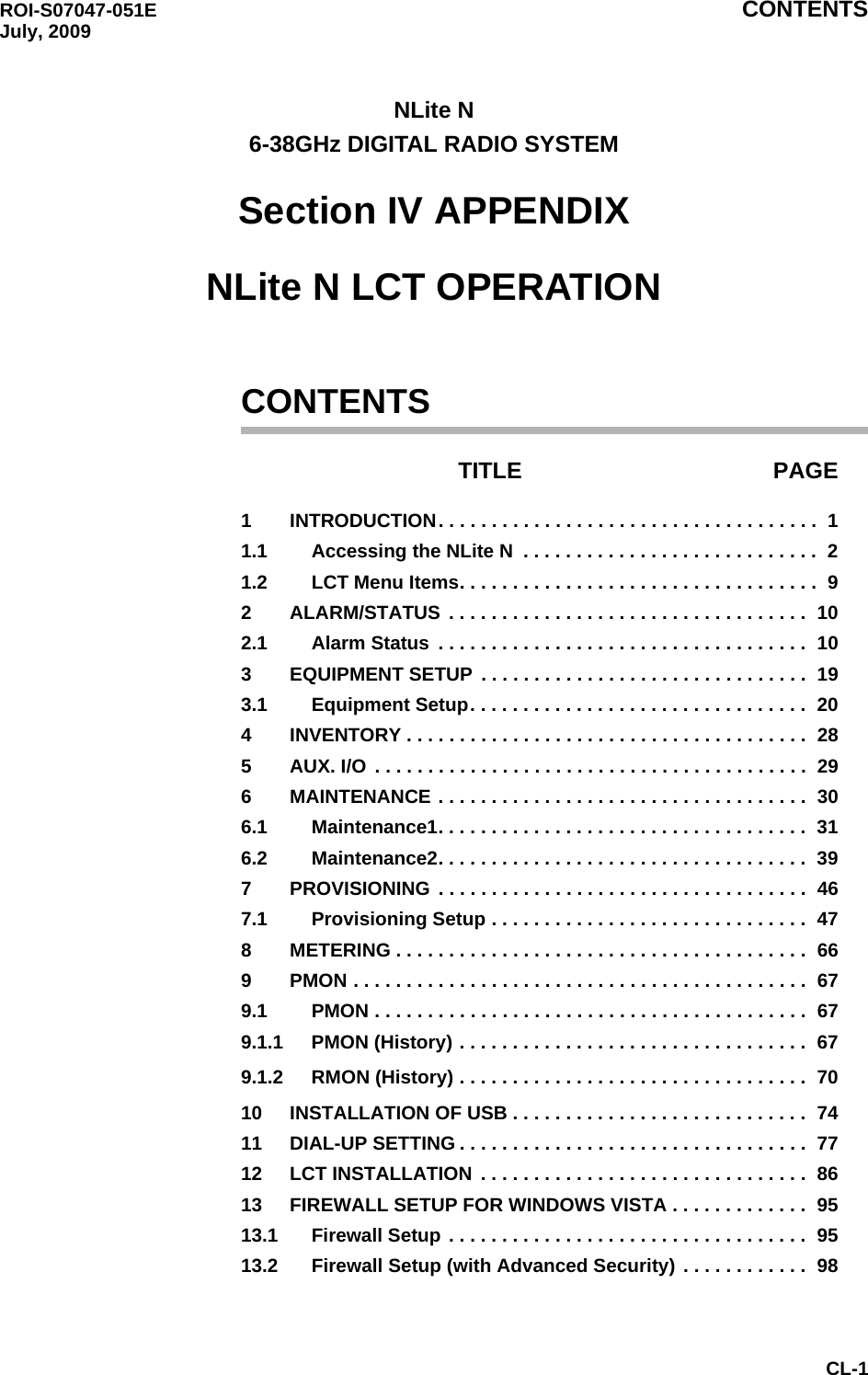
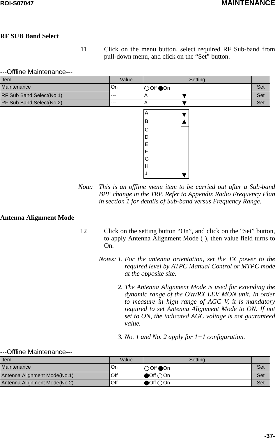
![MAINTENANCE ROI-S07047-32-TX SW Manual Control1 Click on the setting button “On” of the “Maintenance” and clickon the “Set” button, then value field of the Maintenance turnsfrom “Off” to “On”.In Maintenance “On” mode, external parallel alarm outputsexcepts CPU and PS ALM are masked and automatic control isinhibited.Control operation using LCT must be performed inMaintenance “On” condition.2 Click on the setting button “Auto”, “No. 1” or “No. 2” TX SWto select TX SW control mode and click on the “Set” button,then the value field of the corresponding SW manual controlchange to the selected mode.Auto: Normal operation modeNo. 1 or No. 2: Manual control modeATPC Manual Control3 Click on the setting button “On” and enter attenuation valuewithin ATPC range, then click on the “Set” button.---Maintenance1---Item Value SettingMaintenance On Off On SetTX SW Manual Control Auto Auto No.1 No.2 SetRX SW Manual Control Auto Auto No.1 No.2 Set---Maintenance1---Item Value SettingMaintenance On Off On SetATPC Manual Control(No.1) On Off On [dB] SetATPC Manual Control(No.2) Off Off On SetModulationMode Frequency Band(GHz) 5.8L6U611182324 38QPSK ATPC Range 0 to 30 dB 0 to 25 dBMTPC Range 0 to 30 dB 0 to 25 dB16QAM ATPC Range 0 to 24 dBMTPC Range 0 to 24 dB32QAM ATPC Range 0 to 23 dBMTPC Range 0 to 23 dB *10 to 23 dB64QAM ATPC Range 0 to 20 dBMTPC Range 0 to 20 dB *10 to 20 dB128QAM ATPC Range 0 to 20 dBMTPC Range 0 to 20 dB *10 to 20 dBNote:*1 Additional attenuator from 0 to 5 dB can be added.](https://usermanual.wiki/NEC-of-America/58155N.User-Manual-Part-V/User-Guide-1263945-Page-34.png)
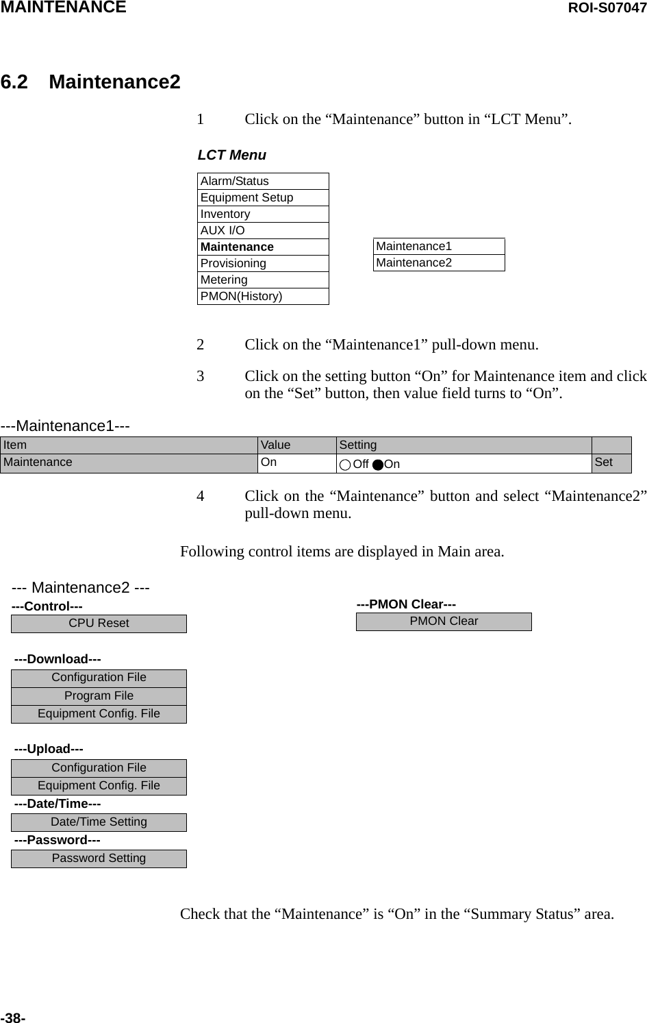
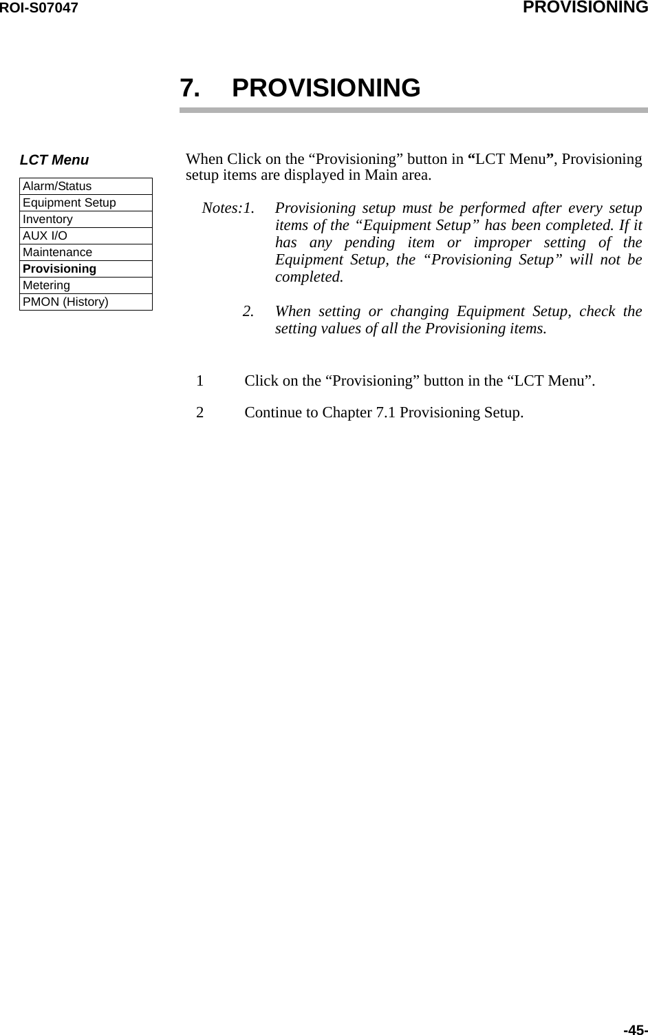
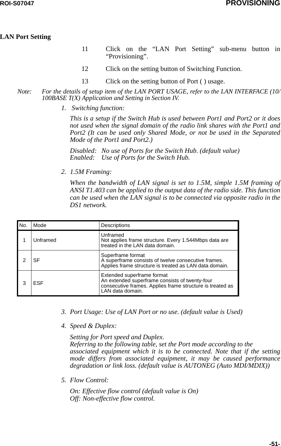
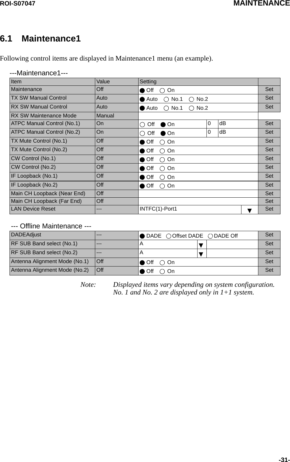
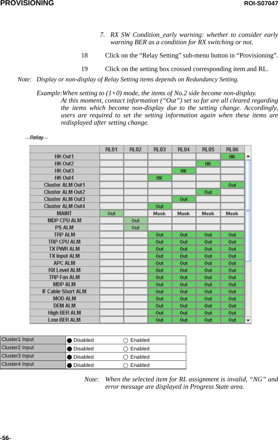
![PROVISIONING ROI-S07047-54-TX Power Control14 Click on the “TX Power Control” sub-menu button in“Provisioning”.15 Enter required values in each control entry field within specifiedrange.(1) ATPC mode in 1+0 or Hot Standby configuration(2) ATPC mode in Twinpath configuration(3) MTPC mode in Twinpath configuration Notes: 1. No.1 and No.2 are indicated in Twinpath configuration only.2. For Hot Standby configuration, the TX Power Control effects bothNo. 1 and No. 2 TRPs.3. ATPC/MTPC Range varies depending on RF frequency band andmodulation scheme.4. ATPC Threshold level Range varies depending on modulationscheme and RF signal channel separation.5. ATPC power mode: (output power when ATPC control signal fails)Hold: Maintain the current TX output level at the time of theATPC is malfunction.---TX Power Control--- RangeATPC Threshold Level [dBm] -60 -80 to -30Additional ATT [dB] 0 0 to 5ATPC Range(MAX) [dB] 0 -30 to 0ATPC Range(MIN) [dB] -30ATPC Power Mode Hold MAX MINCOMM Alarm Mode *6 Mute Hold---TX Power Control--- RangeATPC Threshold Level (No.1) [dBm] -60 -80 to -30ATPC Threshold Level (No.2) [dBm] -60 -80 to -30Additional ATT (No.1) [dB] 0 0 to 5Additional ATT (No.2) [dB] 0 0 to 5ATPC Range(MAX) (No.1) [dB] 0 -30 to 0ATPC Range(MIN) (No.1) [dB] -30ATPC Range(MAX) (No.2) [dB] 0 -30 to 0ATPC Range(MIN) (No.2) [dB] -30ATPC Power Mode Hold MAX MINCOMM Alarm Mode *6 Mute Hold---TX Power Control--- RangeMTPC TX Power (No.1) [dB] 0 -30 to 0MTPC TX Power (No.2) [dB] 0 -30 to 0ATPC Threshold Level (No.1) [dBm] -60 -80 to -30ATPC Threshold Level (No.2) [dBm] -60 -80 to -30Additional ATT (No.1) [dB] 0 0 to 5Additional ATT (No.2) [dB] 0 0 to 5COMM Alarm Mode *6 Mute Hold](https://usermanual.wiki/NEC-of-America/58155N.User-Manual-Part-V/User-Guide-1263945-Page-56.png)
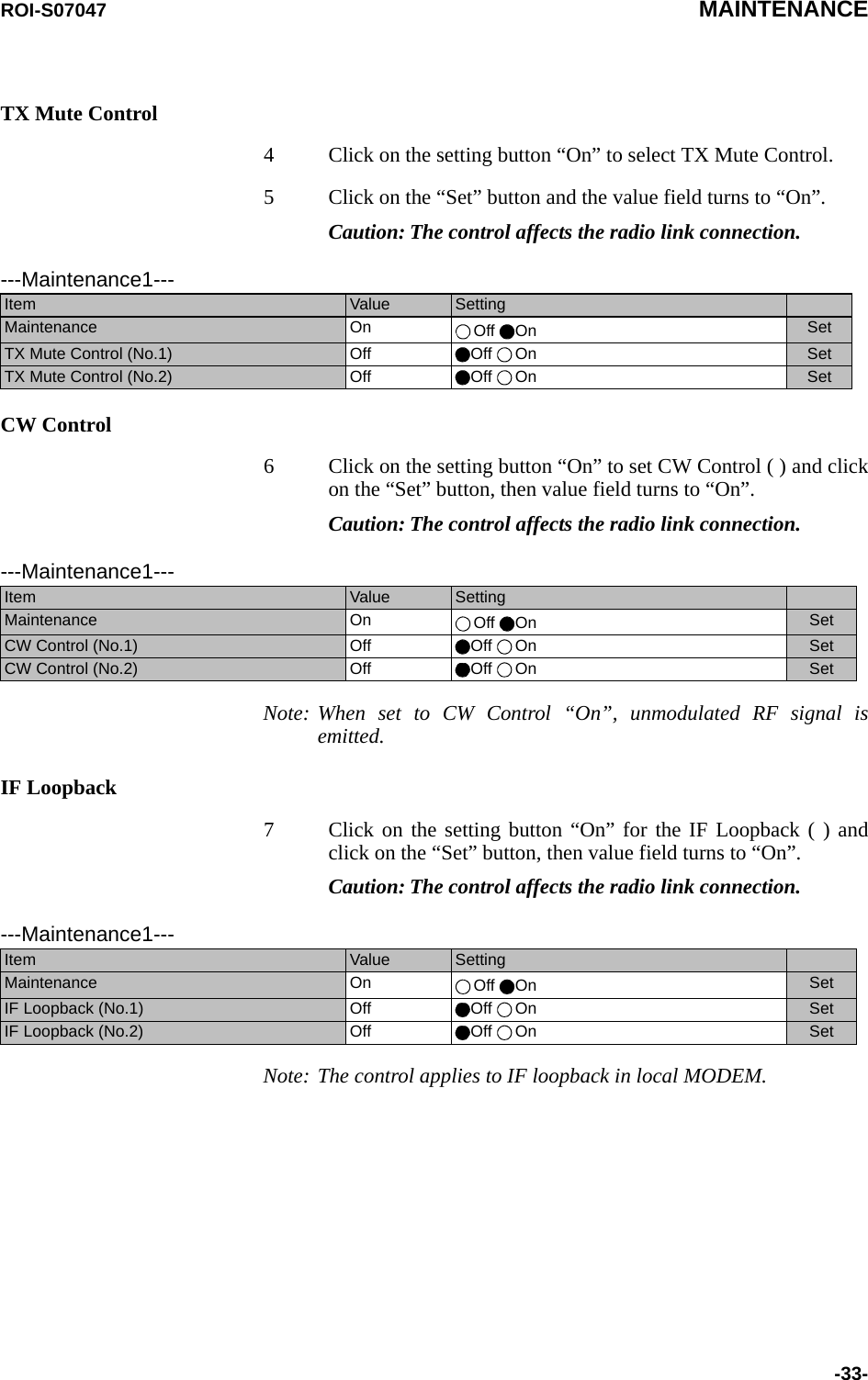
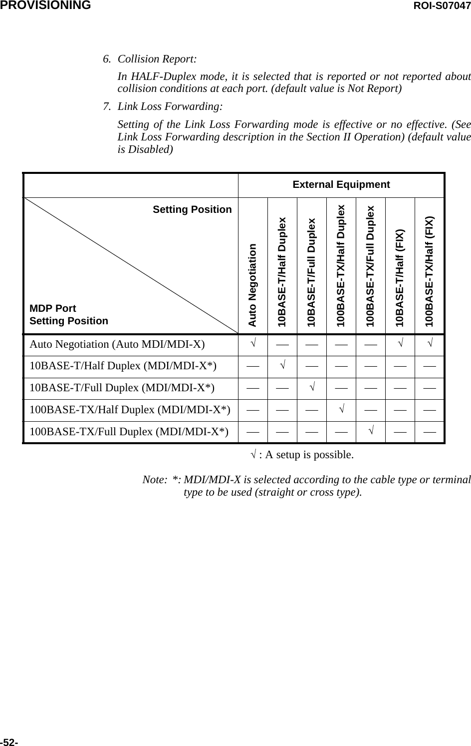
![ROI-S07047 PROVISIONING-61-PMON Select22 Click on the “PMON Select” sub-menu button in“Provisioning”.23 Enter required “RX Level TCN Threshold” level in text field.24 Click on the control button of “SES Activation Condition”.---PMON Select---RX Level TCN Threshold [dBm] −82.0SES Activation Condition 30[%] 15[%]](https://usermanual.wiki/NEC-of-America/58155N.User-Manual-Part-V/User-Guide-1263945-Page-63.png)
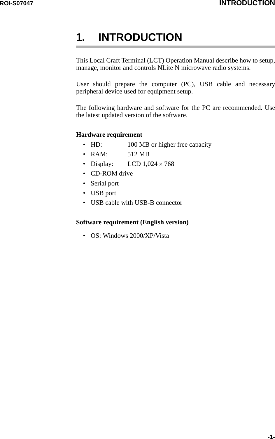
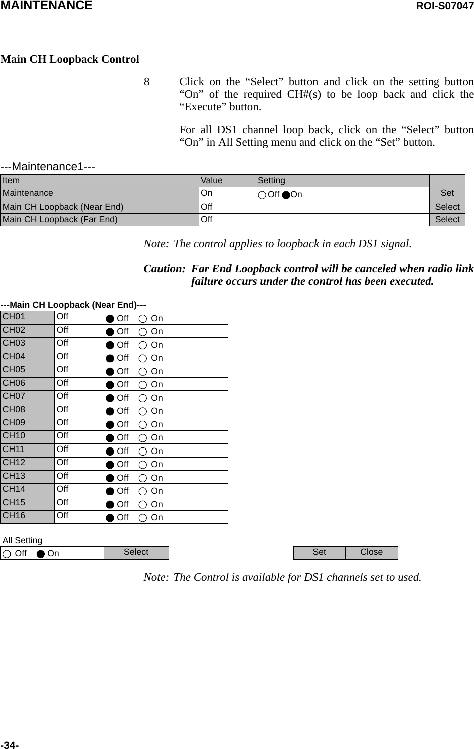
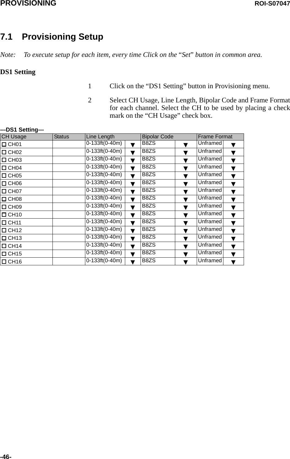
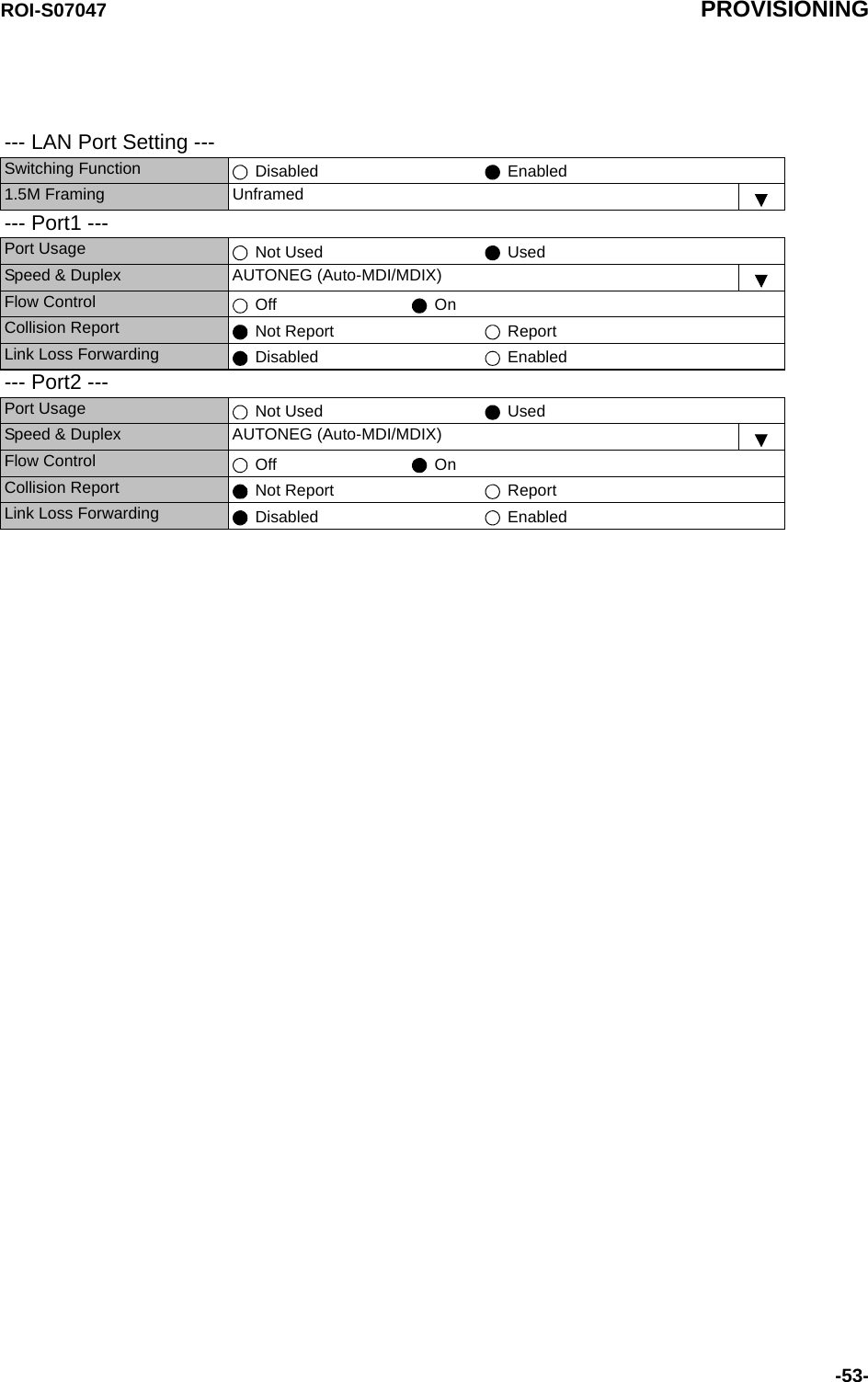
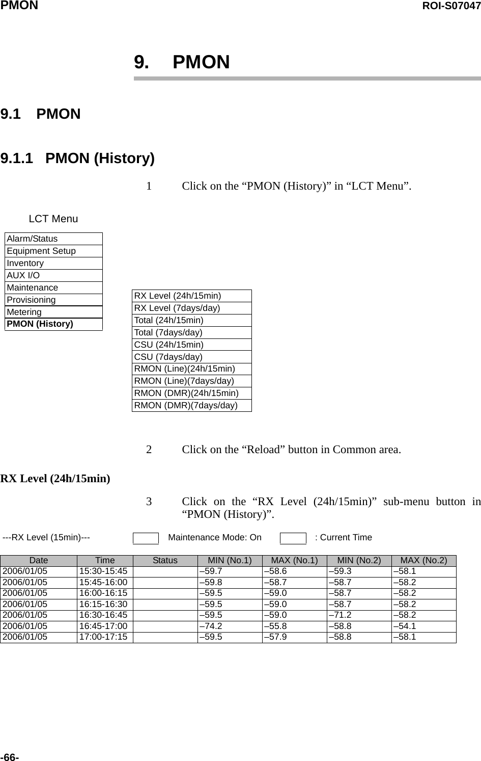
![ROI-S07047 METERING-65-8. METERING1 Click on the “Metering” in “LCT Menu”. 2 Check the values indicated in metering text fields for eachmetering item.Notes: 1. No.1 and No.2 are indicated only for 1+1 configuration.2. Both TX Power values of No.1 and No.2 are indicated inTwinpath configuration only.3. TX Power value * is indicated for standby TRP in HotStandby configuration.4. Power Supply voltage of the TRP DC input variesdepending on IF cable length.5. During total number of erroneous bits and total numberof correctly received bits are calculating, “Calculating”is displayed.LCT MenuAlarm/StatusEquipment SetupInventoryAUX I/OMaintenanceProvisioningMeteringPMON (History)----Metering---No.1 No.2TX Power [dBm] +0.7 *RX Level [dBm] –65.2 –70.0Power Supply [V] –45 –45BER *.*E-10 Calculating](https://usermanual.wiki/NEC-of-America/58155N.User-Manual-Part-V/User-Guide-1263945-Page-67.png)
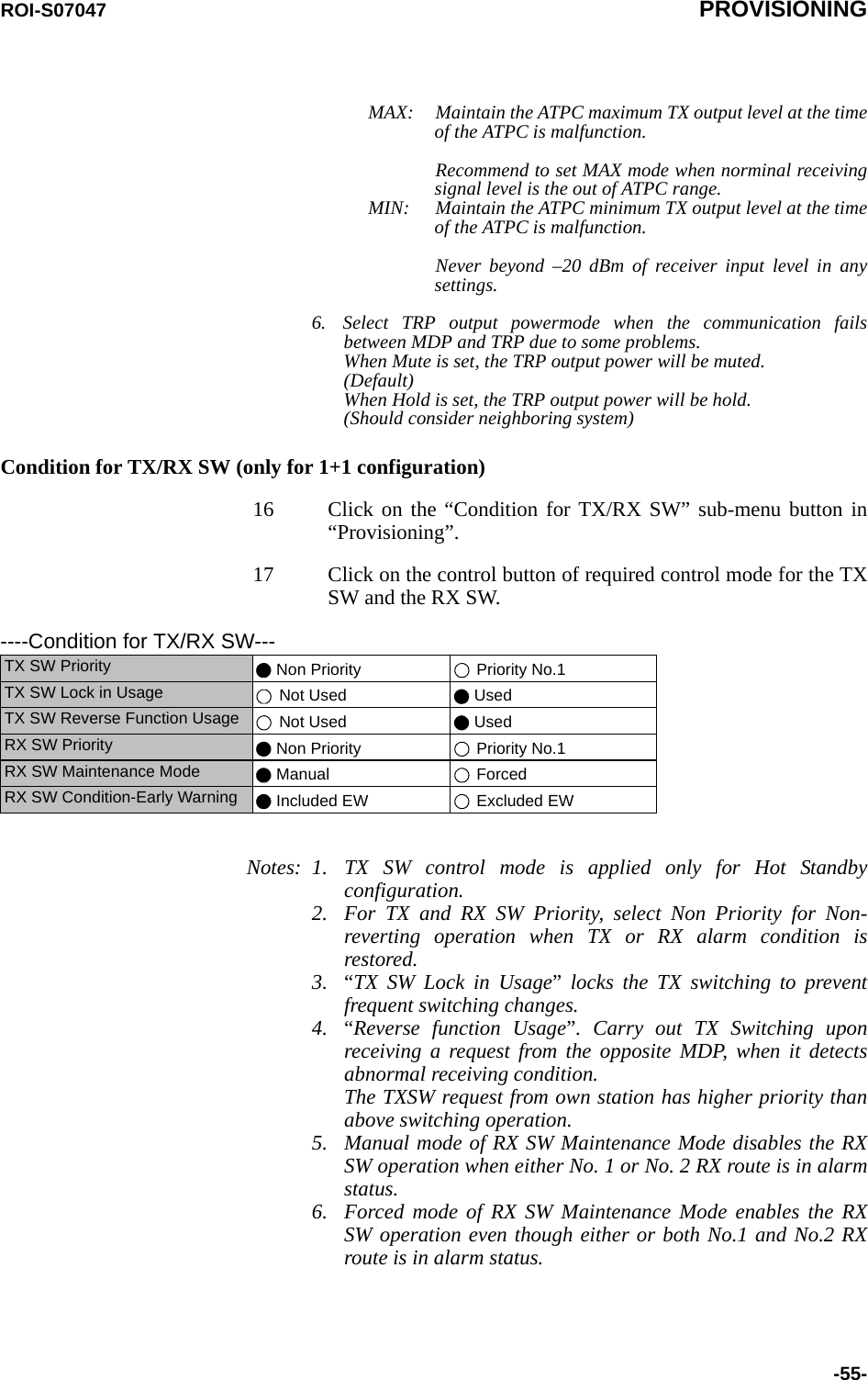
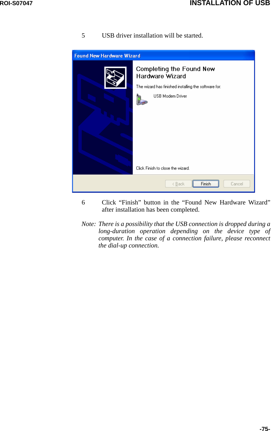
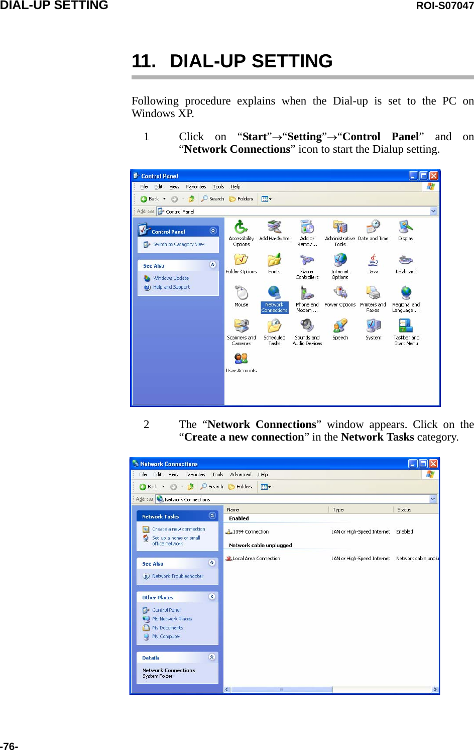
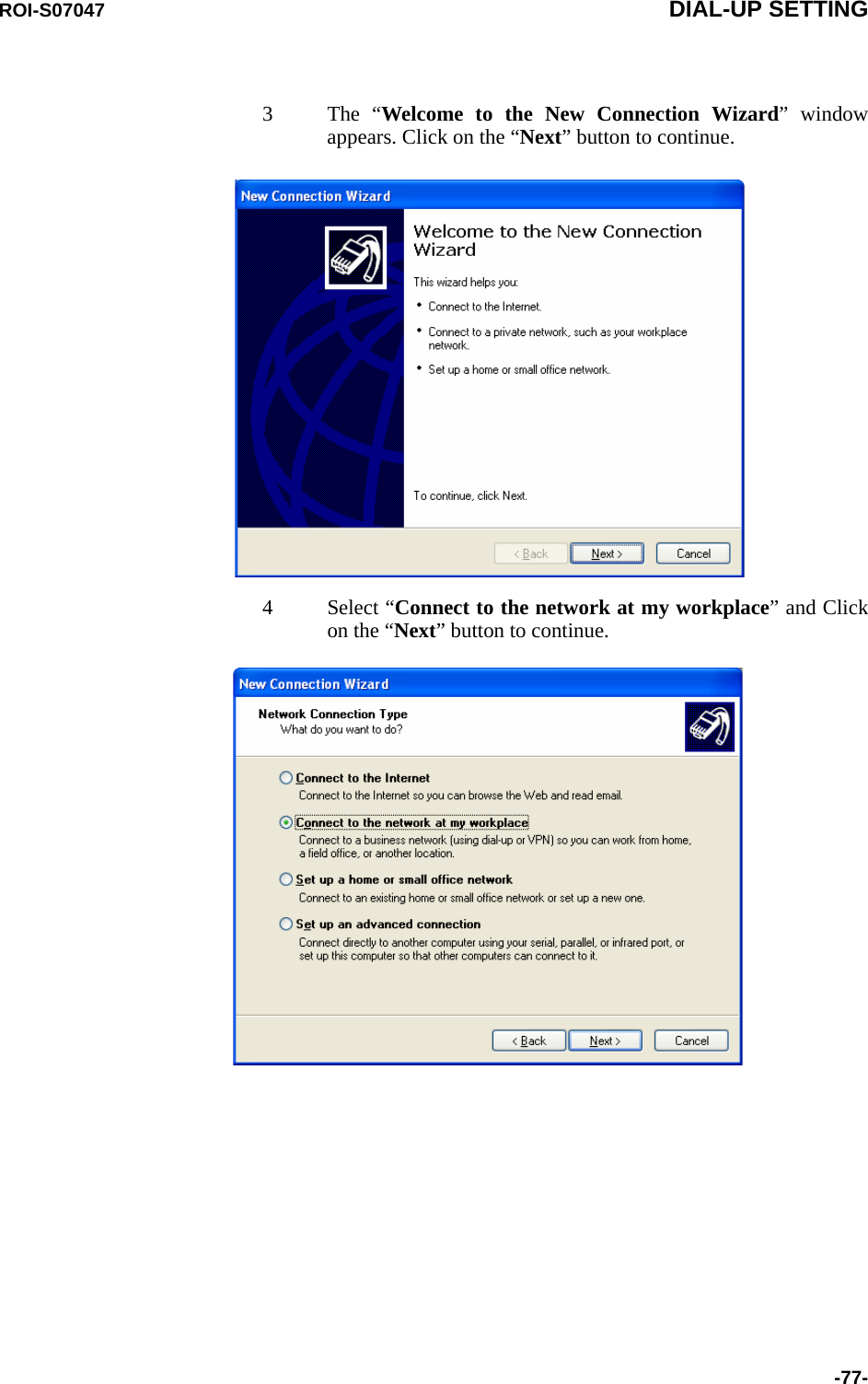
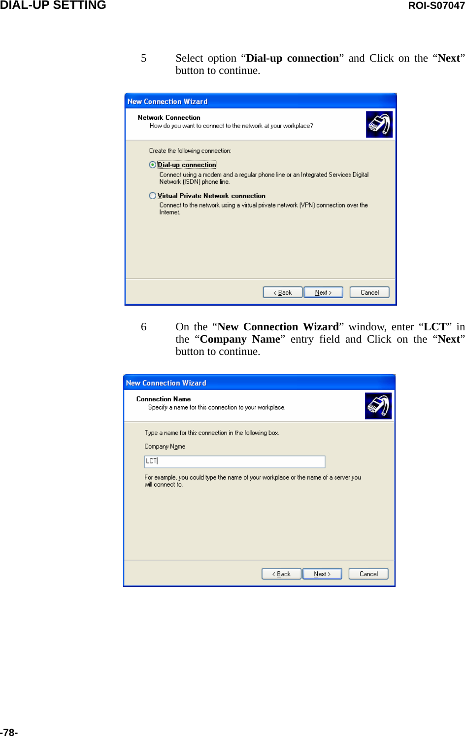
![ROI-S07047 INSTALLATION OF USB-73-10. INSTALLATION OF USBFollowing procedure explains how to install the USB modem driver to awindows XP PC.1 Connect the PC with a USB cable between the LCT port and theUSB port.2 Select “Install from a list or specific location [Advanced]” andClick on the “Next” button.](https://usermanual.wiki/NEC-of-America/58155N.User-Manual-Part-V/User-Guide-1263945-Page-75.png)
![INSTALLATION OF USB ROI-S07047-74-3 Insert the CD-ROM of the USB driver to the PC and select“Search for the best driver in these locations” and check“Search removal media [floppy, CD-ROM...],” then, Click onthe “Next” button. 4 Click “Continue Anyway” button in the Hardware Installationalert pop-up.](https://usermanual.wiki/NEC-of-America/58155N.User-Manual-Part-V/User-Guide-1263945-Page-76.png)

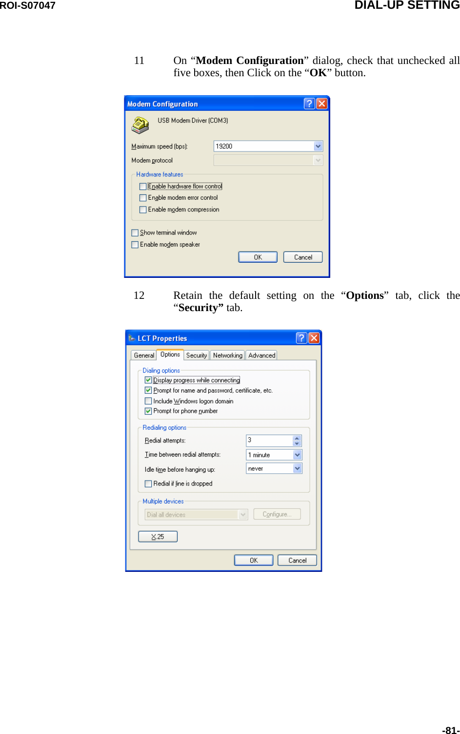
![DIAL-UP SETTING ROI-S07047-80-9On “Connect LCT” dialog, click “Properties”.10 Verify that “Modem-USB Modem Driver [COM(#)]” isdisplayed on the General dialog box connect using check box,and select “Show icon in notification area when connected” inthe LCT Properties dialog. Then, Click on the “Configure”button.](https://usermanual.wiki/NEC-of-America/58155N.User-Manual-Part-V/User-Guide-1263945-Page-82.png)