NEC of America 58155N NLite N 5.8 GHz Digital Microwave Radio User Manual LCT
NEC Corporation of America NLite N 5.8 GHz Digital Microwave Radio LCT
Contents
User Manual - Part V

ROI-S07047-051E CONTENTS
July, 2009
CL-1
NLite N
6-38GHz DIGITAL RADIO SYSTEM
Section IV APPENDIX
NLite N LCT OPERATION
CONTENTS
TITLE PAGE
1 INTRODUCTION. . . . . . . . . . . . . . . . . . . . . . . . . . . . . . . . . . . . 1
1.1 Accessing the NLite N . . . . . . . . . . . . . . . . . . . . . . . . . . . . 2
1.2 LCT Menu Items. . . . . . . . . . . . . . . . . . . . . . . . . . . . . . . . . . 9
2 ALARM/STATUS . . . . . . . . . . . . . . . . . . . . . . . . . . . . . . . . . . 10
2.1 Alarm Status . . . . . . . . . . . . . . . . . . . . . . . . . . . . . . . . . . . 10
3 EQUIPMENT SETUP . . . . . . . . . . . . . . . . . . . . . . . . . . . . . . . 19
3.1 Equipment Setup. . . . . . . . . . . . . . . . . . . . . . . . . . . . . . . . 20
4 INVENTORY . . . . . . . . . . . . . . . . . . . . . . . . . . . . . . . . . . . . . . 28
5 AUX. I/O . . . . . . . . . . . . . . . . . . . . . . . . . . . . . . . . . . . . . . . . . 29
6 MAINTENANCE . . . . . . . . . . . . . . . . . . . . . . . . . . . . . . . . . . . 30
6.1 Maintenance1. . . . . . . . . . . . . . . . . . . . . . . . . . . . . . . . . . . 31
6.2 Maintenance2. . . . . . . . . . . . . . . . . . . . . . . . . . . . . . . . . . . 39
7 PROVISIONING . . . . . . . . . . . . . . . . . . . . . . . . . . . . . . . . . . . 46
7.1 Provisioning Setup . . . . . . . . . . . . . . . . . . . . . . . . . . . . . . 47
8 METERING . . . . . . . . . . . . . . . . . . . . . . . . . . . . . . . . . . . . . . . 66
9 PMON . . . . . . . . . . . . . . . . . . . . . . . . . . . . . . . . . . . . . . . . . . . 67
9.1 PMON . . . . . . . . . . . . . . . . . . . . . . . . . . . . . . . . . . . . . . . . . 67
9.1.1 PMON (History) . . . . . . . . . . . . . . . . . . . . . . . . . . . . . . . . . 67
9.1.2 RMON (History) . . . . . . . . . . . . . . . . . . . . . . . . . . . . . . . . . 70
10 INSTALLATION OF USB . . . . . . . . . . . . . . . . . . . . . . . . . . . . 74
11 DIAL-UP SETTING . . . . . . . . . . . . . . . . . . . . . . . . . . . . . . . . . 77
12 LCT INSTALLATION . . . . . . . . . . . . . . . . . . . . . . . . . . . . . . . 86
13 FIREWALL SETUP FOR WINDOWS VISTA . . . . . . . . . . . . . 95
13.1 Firewall Setup . . . . . . . . . . . . . . . . . . . . . . . . . . . . . . . . . . 95
13.2 Firewall Setup (with Advanced Security) . . . . . . . . . . . . 98
CONTENTS ROI-S07047
CL-2
2 pages
(This page is intentionally left blank.)

ROI-S07047 INTRODUCTION
-1-
1. INTRODUCTION
This Local Craft Terminal (LCT) Operation Manual describe how to setup,
manage, monitor and controls NLite N microwave radio systems.
User should prepare the computer (PC), USB cable and necessary
peripheral device used for equipment setup.
The following hardware and software for the PC are recommended. Use
the latest updated version of the software.
Hardware requirement
• HD: 100 MB or higher free capacity
•RAM: 512 MB
• Display: LCD 1,024 × 768
•CD-ROM drive
• Serial port
•USB port
• USB cable with USB-B connector
Software requirement (English version)
• OS: Windows 2000/XP/Vista
INTRODUCTION ROI-S07047
-2-
1.1 Accessing the NLite N
This section explains the LCT connections and Startup Method (Procedure)
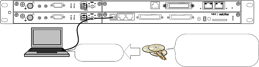
LCT software should be first installed in the PC from the supplied CD-
ROM, referring to installation procedure in the chapters 10 to 12.
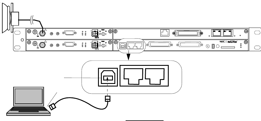
1 Connect the Computer (PC) with a USB cable between the LCT
port and the USB port.
NLite N MDP
USB Driver USB Driver
LCT Setup File
LCT Application
Note: For the LCT Application Rev. 2.01.xxx,
LCT Application
setup_LCT_NLite_N_rev_
2_xx_xxx_Full.exe
execute the installation with the”setup_LCT_NLite_N_rev_2_xx_xxx_Full.exe”.
SELV
!
AUX/ALM
LCT NMS NE SC IN/OUT EOW
PROTECT
CALL MMC
MAINT
MEMORY
MDP
XIF IN XIF OUT
IF IN/OUT TX
RX
RESET
XPIC CTRL XPIC
PWR
TRP
MD/
CBL PWR
PULL
G
SELV
!
XIF IN XIF OUT
IF IN/OUT TX
RX
RESET
XPIC CTRL XPIC
PWR
TRP
MD/
CBL PWR
PULL
G
G
ALM
100M PORT 1 PORT 2 100M
Ns
Ns
WS IN/OUT Ns
N
DS1 IN/OUT
ROI-S07047 INTRODUCTION
-3-
Notes: USB modem driver should be installed first before creating
the dial-up connection.
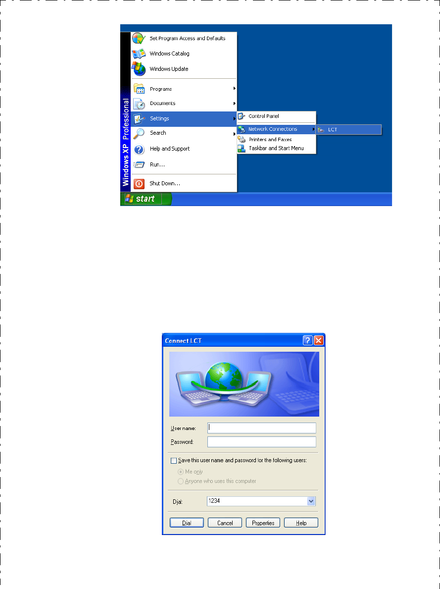
2 Click on the “START” menu button, select “Settings”,
“Network Connections”, “LCT”, then, “Connect LCT” dial-up
dialog is appeared.
USB Cable
PC for LCT
USB port
NLite N MDP
LCT NMS NE
NLite N TRP
LCT port
LCT SETUP
*Use the typical USB shielded cable.
(Do not use the un-shielded cable
)
SELV
!
AUX/ALM SC IN/OUT EOW
PROTECT
CALL MMC
MAINT
MEMORY
MDP
XIF IN XIF OUT
IF IN/OUT TX
RX
RESET
XPIC CTRL XPIC
PWR
TRP
MD/
CBL PWR
PULL
G
SELV
!
XIF IN XIF OUT
IF IN/OUT TX
RX
RESET
XPIC CTRL XPIC
PWR
TRP
MD/
CBL PWR
PULL
G
G
ALM
100M PORT 1 PORT 2 100M
Ns
Ns
WS IN/OUT Ns
N
DS1 IN/OUT
LCT NMS NE
INTRODUCTION ROI-S07047
-4-
3 The dialog box “Connect LCT” appears.
4 Click on the “Dial” button, then the PC is connected to the
MDP.
ROI-S07047 INTRODUCTION
-5-
Note: There is a possibility that the USB connection is dropped during a
long-duration operation depending on the device type of
computer. In the case of a connection failure, please reconnect
the dial-up connection.
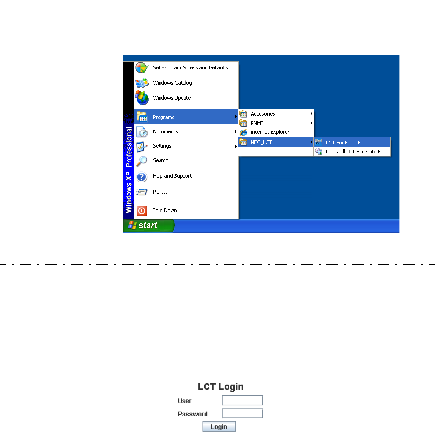
6 Enter User ID and password in User/Password entry fields and
press the “Login” button.
5 Double click on the short-cut icon or select the “Programs”
→ “NEC_ LCT” → “LCT For NLite N” from the “start”
menu.
INTRODUCTION ROI-S07047
-6-
Default password of Admin is defined as “12345678”
The password can be changed by Administrator privilege. The LCT
operator must have the security system privilege to control of NLite N
systems. (The password change is described in Chapter 6.2 Maintenance
2)
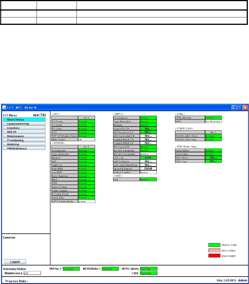
7 Following LCT Open View is displayed.
(Cascaded Alarm/Status items are displayed in Main area by
default.)
User ID Pass Word Privilege
Admin ******** Access to the LCT and control
User (non password) Access to the LCT (monitor only)
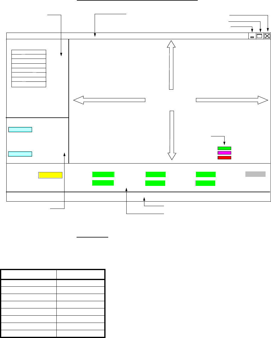
NLite N LCT Open View (Example)
ROI-S07047 INTRODUCTION
-7-
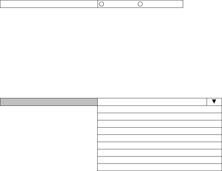
Symbols in the Open View are described as follows.
Description of the LCT Menu Conventions
LCT Menu
“Set” button appears/disappears depending on the Menu item selected in
the “LCT Menu”.
Main area
Menu area
Common area
Alarm Status
Equipment Setup
Inventory
AUX I/O
Maintenance
Provisioning
Metering
PMON(History)
LCT Menu
Maintenance On
Summary Status area
Progress State area
Title
Logout
Common
Progress State:
Close
Maximize
Minimize
Title bar
Summary Status
TRP No.1 Normal MODEM No.1
MODEM No.2
TRP No.2 Normal
Normal
Normal
INTFC(Main)
CTRL
Normal
Normal
INTFC(Sub)
Admin
Set
Normal State
Minor Alarm
Major Alarm
Criteria
LCT Menu Set
Alarm/Status disappear
Equipment Setup appear
Inventory disappear
AUX I/O appear
Maintenance disappear
Provisioning appear
Metering disappear
PMON (History) disappear
INTRODUCTION ROI-S07047
-8-
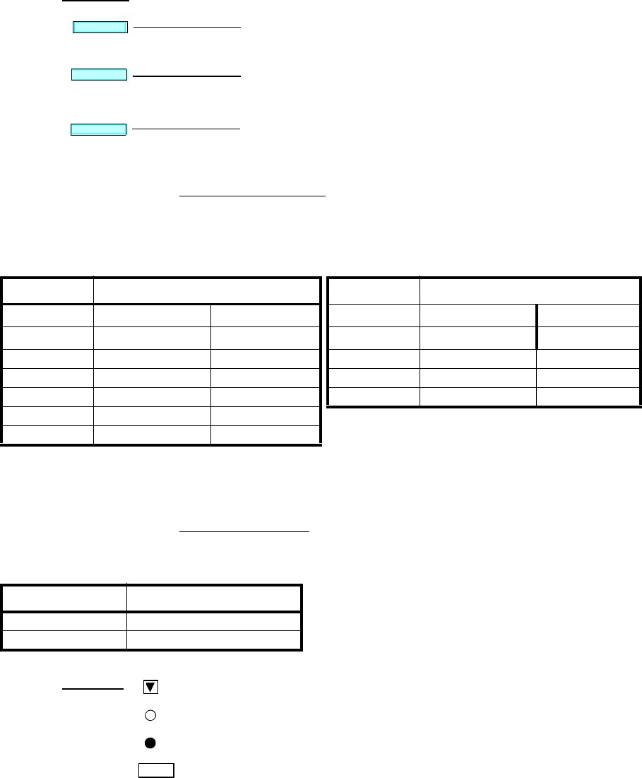
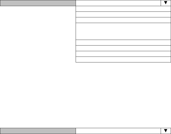
Summary Status Area
Following summary items show the operating status.
Note: When the TRP No. 2, MODEM No. 2 is not mounted,
corresponding item is colored gray.
Progress State Area
Following Response is displayed. When “Set” button is clicked.
Execute all the changes made in the items shown in the main
area by the selected “LCT Menu”.
Displays confirmation box to Logout. Clicking Logout button,
the LCT screen is logged out and the Login screen is displayed.
Reload recent data to display.
Common
Logout
Reload
Set
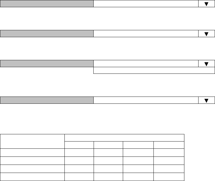
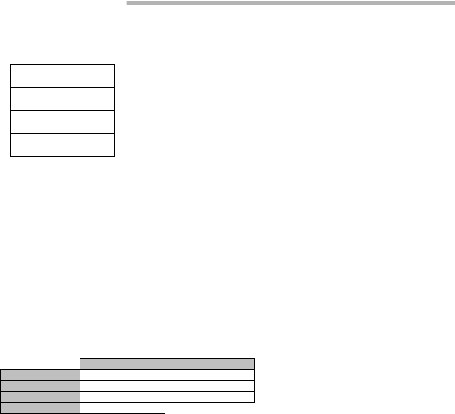
For 1+1 Configuration For 1+0 Configuration
Item Status Indication Item Status Indication
Maintenance On (yellow) Off (white) Maintenance On (yellow) Off (white)
TRP No.1 Normal (green) Alarm (red) TRP Normal (green) Alarm (red)
TRP No.2 Normal (green) Alarm (red) MODEM Normal (green) Alarm (red)
MODEM No.1 Normal (green) Alarm (red) INTFC (Main) Normal (green) Alarm (red)
MODEM No.2 Normal (green) Alarm (red) CTRL Normal (green) Alarm (red)
INTFC (Main) Normal (green) Alarm (red)
CTRL Normal (green) Alarm (red)
SET Control Response
OK - Response OK
NG - Response NG
:Menu Button displays pull-down menu
:No Selected
:Selected
Set :Execute control/setup for each item
Symbol;

ROI-S07047 INTRODUCTION
-9-
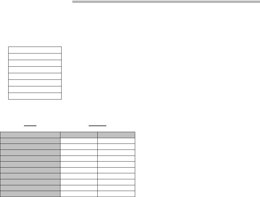
1.2 LCT Menu Items
LCT Menu is consisted of the following table.
Notes:*1:Only provides for 1+1 configuration.
*2:Only provides for LAN.
LCT Menu Sub-menu Remarks
Alarm/Sataus Refer to “2.ALARM/STATUS”
Equipment Setup Refer to “3.EQUIPMENT SETUP”
Inventory Refer to “4.INVENTORY”
AUX I/O Refer to “5.AUX.I/O”
Maintenance Refer to “6.MAINTENANCE”
Maintenence1
Maintenence2
Provisioning Refer to “7.PROVISIONING”
DS1 Setting
WS Setting
BER Threshold Setting
SC Assignment
LAN Port Setting
TX Power Control
Condition for TX/RX SW *1
Relay Setting
TCN Threshold (15min)
TCN Threshold (1day)
PMON Select
In-band Loopback Setting
Others
Metering Refer to “8.METERING”
PMON (History) Refer to “9.PMON”
RX Level (24h/15min)
RX Level (7days/day)
Total (24h/15min)
Total (7days/day)
CSU (24h/15min)
CSU (7days/day)
RMON (Line)(24h/15min) *2
RMON (Line)(7days/day) *2
RMON (DMR)(24h/15min) *2
RMON (DMR)(7days/day) *2
ALARM/STATUS ROI-S07047
-10-
2. ALARM/STATUS
2.1 Alarm Status
Notes: Item (*1) is displayed in Hot Standby configuration only.
Item (*2) is displayed in Hot Standby and Twinpath configuration.
---TRP---
Item Status
No.1 No.2
TX Power Normal Normal
TX Input Normal Normal
RX Level Normal Normal
APC Normal Normal
TRP CPU/Cable Open Normal Normal
Mute Status Off Off
TX SW Lock in Status Normal (*1)
TX SW Reverse REQ Normal (*1)
TX SW Status No.1 (*1)
RX SW Status No.2 (*2)
LCT Menu
Alarm/Status
Equipment Setup
Inventory
AUX I/O
Maintenance
Provisioning
Metering
PMON (History)
When click on the “Alarm/Status” button in “LCT Menu”, following
items/status (sample) are displayed in Main Area.
ALM items are listed in Table 2-1.
Alarm/Status items are displayed in Main area in default when accessing
the LCT.
Note: Alarm/Status indication varies depending on the system
configuration.

ROI-S07047 ALARM/STATUS
-11-
---MODEM---
Item Status
No.1 No. 2
Unequipped Normal Normal
Type mismatch Normal Normal
Module Normal Normal
LOF Normal Normal
Frame ID Normal Normal
High BER Normal Normal
Low BER Normal Normal
Early Warning Normal Normal
MOD Normal Normal
DEM Normal Alarm
Input Voltage Normal Normal
Power Supply Normal Normal
IF Cable Short Normal Normal
Cable EQL Normal Normal
Linearizer Function OPR NON OPR
Linearizer Normal Normal
ATPC Power Mode Active Active
---CTRL---
Item Status
CTRL Module Normal
MMC Not Mounted
---UAE---
Item Status
UAE Normal
ALARM/STATUS ROI-S07047
-12-
Click on the corresponding item in status block (*1)(*2)(*3) details status
for following “Alarm/Status (16CH)*” is displayed.
Click on the corresponding item in status block (*4) details status for
following LAN PORT is displayed.
Clicking “Close” button dismisses the “Alarm/Status” table.
Note*: Maximum 16 CH
---INTFC---
Item Status
Unequiped Normal
Type Mismatch Normal
Module Normal
Input LOS CH Normal
AIS Received CH Normal (*1)
AIS Generated CH Normal
Usage Error CH Normal
In-band NELB CH Normal (*2)
In-band FELB CH Normal (*3)
WS Input LOS Normal
WS AIS Received Normal
WS AIS Generated Normal
LAN Link Normal
LAN Collision Normal (*4)
Link Loss Forwarding Normal (for LAN only)
Speed & Duplex Detail...
Inphase Inphase
(*1)
CH No. Status
Input LOS AIS Received AIS Generated Usage Error
CH01 Normal Normal Normal Normal
CH02 Normal Normal Normal Normal
CH03 Normal Normal Normal Normal
CH04 Normal Normal Normal Normal
CH05 Normal Normal Normal Normal
:::::
:::::
CH15 Normal Normal Normal Normal
CH16 Normal Normal Normal Normal
Close

ROI-S07047 ALARM/STATUS
-13-
(*2)
---In-band Near End Loopback Status CH---
Clicking Close button dismisses the Alarm/Status table.
Note*:Maximum 16CH
(*3)
---In-band Far End Loopback Status CH---
Clicking Close button dismisses the Alarm/Status table.
Note*:Maximum 16CH
CH No. Status
Status
CH01 Normal
CH02 Normal
CH03 Normal
CH04 Normal
CH05 Normal
CH06 Normal
CH07 Normal
CH08 Normal
CH09 Normal
CH10 Normal
CH11 Normal
CH12 Normal
CH13 Normal
CH14 Normal
CH15 Normal
CH16 Normal
Close
CH No. Status
Status
CH01 Normal
CH02 Normal
CH03 Normal
CH04 Normal
CH05 Normal
CH06 Normal
CH07 Normal
CH08 Normal
CH09 Normal
CH10 Normal
CH11 Normal
CH12 Normal
CH13 Normal
CH14 Normal
CH15 Normal
CH16 Normal
Close
ALARM/STATUS ROI-S07047
-14-
(*4)
Note: 1.Link:
Displaying LINK Status for respective Port.
2.Collision:
Displaying occurrence of Collision status in Half Duplex
mode for respective Port.
3.LLF:
Forced LINK off control status detecting the link loss of the
facing equipment for respective Port.
4.Speed & Duplex:
Displaying linked mode for respective Port.
Clicking “Close” button dismisses the LAN PORT table.
These items (*) are displayed only when LAN transmission is configured to the system.
For the details, refer to Appendix LAN INTFC (10/100BASE-T(X)) Application and
Setting in this Section IV.
Item Status
LAN Link Normal (*)
LAN Collision Normal (*)
Link Loss Forwarding (LLF) Normal (*)
Speed & Duplex Detail. (*)
Port No. Status
Link Collision LLF Speed & Duplex
Port1 Link Normal Normal 100M-Half(MDI)
Port2 Link Normal Normal 100M-Half(MDI)
Close
---TCN-RX LEV---
Item Status
No.1 No.2
TCN-RX LEV-15min Normal Normal
TCN-RX LEV-1day Normal Normal
---TCN 15min 1day---
Item Status
Total-15min Normal
Total-1day Normal
CSU-15min Normal (*1)
CSU-1day Normal (*2)
ROI-S07047 ALARM/STATUS
-15-
(*1)
---CSU-15min---
(*2)
---CSU-1day---
CH No. Status
Incoming CV-L Incoming CV-P Outgoing CV-P
CH01 Normal Normal Normal
CH02 Normal Normal Normal
CH03 Normal Normal Normal
CH04 Normal Normal Normal
CH05 Normal Normal Normal
CH06 Normal Normal Normal
CH07 Normal Normal Normal
CH08 Normal Normal Normal
CH09 Normal Normal Normal
CH10 Normal Normal Normal
CH11 Normal Normal Normal
CH12 Normal Normal Normal
CH13 Normal Normal Normal
CH14 Normal Normal Normal
CH15 Normal Normal Normal
CH16 Normal Normal Normal
Close

ALARM/STATUS ROI-S07047
-16-
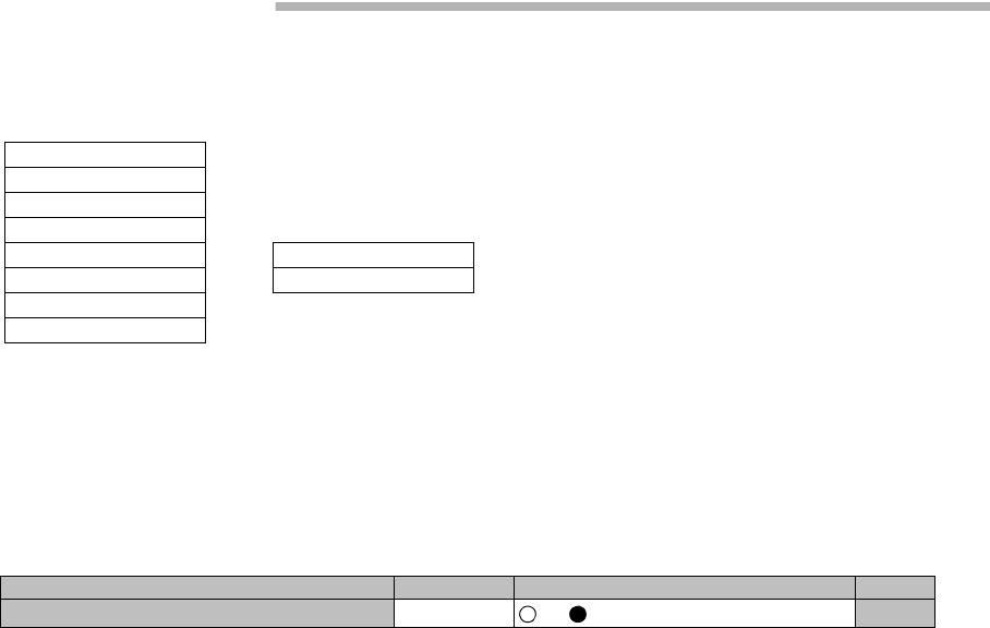
Table 2-1 ALM/Status List (1/3)
No. Alarm/Status Item Event Status Source of
Event Criteria
Default 1+
01+
1
TRP
1TX PWR ALM1 TRP1 output power decreased TRP No.1 Major
2TX PWR ALM2 TRP2 output power decreased TRP No.2 Major *1
3TX Iunpt ALM1 TRP1 TX IF input level decreased TRP No.1 Major
4TX Input ALM2 TRP2 TX IF input level decreased TRP No.2 Major *1
5RX Level ALM1 TRP1 Received level decreased TRP No.1 Major
6RX Level ALM2 TRP2 Received level decreased TRP No.2 Major *1
7APC ALM1 TRP1 LO OSC APC loop out of lock TRP No.1 Major
8APC ALM2 TRP2 LO OSC APC loop out of lock TRP No.2 Major *1
9TRP CPU/CBL OPN ALM1 TRP1 CPU failure or IF cable is open TRP No.1 Major
10 TRP CPU/CBL OPN ALM2 TRP2 CPU failure or IF cable is open TRP No.2 Major *1
11 Mute Status1 TRP1 Mute status TRP No.1 Status
12 Mute Status2 TRP2 Mute status TRP No.2 Status *1
13 TX SW Lock in Status Status of TX SW Lock in function CTRL Status *1
14 TX SW Reverse Request Status of Reverse Function CTRL Status *1
15 TX SW Status Status of TX SW function CTRL Status *1
16 RX SW Status Status of RX SW function CTRL Status *1

ROI-S07047 ALARM/STATUS
-17-
MODEM
17 MODEM 1 UNEQUIP Unequipped or loose contact of the MODEM1 CTRL Major
18 MODEM 2 UNEQUIP Unequipped or loose contact of the MODEM2 CTRL Major *1
19 MODEM Type Mismatch1 Improper MODEM1 Type is installed CTRL Major
20 MODEM Type Mismatch2 Improper MODEM2 Type is installed CTRL Major *1
21 MODEM ALM1 The MODEM1 failure CTRL Major
22 MODEM ALM2 The MODEM2 failure CTRL Major *1
23 LOF1 Loss of Radio frame synchronization in
MODEM1 MODEM No.1 Major
24 LOF2 Loss of Radio frame synchronization in
MODEM2 MODEM No.2 Major *1
25 Frame ID1 ID is no coincidence in MODEM1 MODEM No.1 Major
26 Frame ID2 ID is no coincidence in MODEM2 MODEM No.2 Major *1
27 High BER ALM1 High BER (selectable) is detected in MODEM1 MODEM No.1 Major
28 High BER ALM2 High BER (selectable) is detected in MODEM2 MODEM No.2 Major *1
29 Low BER ALM1 Low BER (selectable) is detected in MODEM1 MODEM No.1 Minor
30 Low BER ALM2 Low BER (selectable) is detected in MODEM2 MODEM No.2 Minor *1
31 Early Warning1 EARLY WARNING is detected in No.1 CH MODEM No.1 Minor
32 Early Warning2 EARLY WARNING is detected in No.2 CH MODEM No.2 Minor *1
33 MOD ALM1 PLL APC unlock output level down CLK loss in
MODEM1 MODEM No.1 Major
34 MOD ALM2 PLL APC unlock output level down CLK loss in
MODEM2 MODEM No.2 Major *1
35 DEM ALM1 Carrier/Frame Asynchronous at MODEM1 MODEM No.1 Major
36 DEM ALM2 Carrier/Frame Asynchronous at MODEM2 MODEM No.2 Major *1
37 Input Voltage ALM1 ALM1 PS1 input over voltage/lower voltage MODEM No.1 Major
38 Input Voltage ALM2 ALM2 PS2 input over voltage/lower voltage MODEM No.2 Major *1
39 PS ALM1 No.1 power supply failure (only1+1) MODEM No.1 Major
40 PS ALM2 No.2 power supply failure (only1+1) MODEM No.2 Major *1
41 IF Cable Short ALM1 IF cable connected to TRP1 short MODEM No.1 Major
42 IF Cable Short ALM2 IF cable connected to TRP2 short MODEM No.2 Major *1
43 Cable EQL FAIL1 Cable EQL control is lost in MODEM1 MODEM No.1 Major
44 Cable EQL FAIL2 Cable EQL control is lost in MODEM2 MODEM No.2 Major *1
45 Linearizer Function1 Status of linearizer function in MODEM1 CTRL Status
46 Linearizer Function2 Status of linearizer function in MODEM2 CTRL Status *1
47 Linearizer Fail1 BB LNZ control is lost in MODEM1 CTRL Major
48 Linearizer Fail2 BB LNZ control is lost in MODEM1 CTRL Major *1
49 ATPC PWR MODE1 No.1 ATPC failure Hold/Maximum/Minimum*2
power output CTRL Status
50 ATPC PWR MODE2 No.2 ATPC failure Hold/Maximum/Minimum*2
power output CTRL Status *1
Table 2-1 ALM/Status List (2/3)
No. Alarm/Status Item Event Status Source of
Event Criteria
Default 1+
01+
1

ALARM/STATUS ROI-S07047
-18-
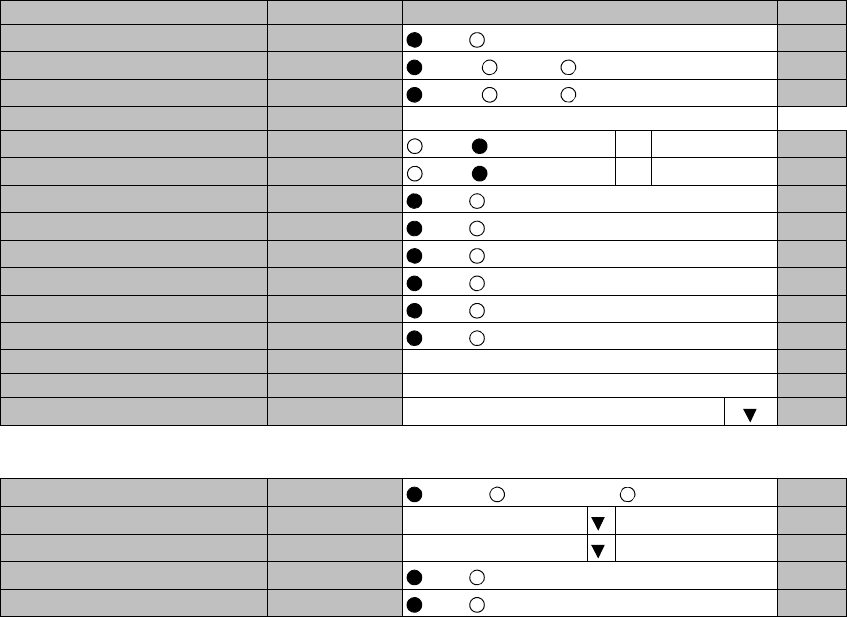
Notes: *1: Not applied.
INTFC Main (1)
51 INTFC (1) UNEQUIP MAIN INTFC is unequipped CTRL Major
52 INTFC (1) Type Mismatch Mounted INTFC differs from configuration setting CTRL Major
53 INTFC (1) ALM Main INTFC total alarm Main INTFC Major
54 INPUT LOS CH01-16 Input signal of CH01-CH16 is lost Main INTFC Major
55 AIS Received CH01-16 AIS in CH01-CH16 is received Main INTFC Status
56 AIS Generated CH01-16 AIS in CH01-CH16 is generated Main INTFC Status
57 CH Usage Error CH01-16 Input signal is detected in unused CH01-CH16 Main INTFC Minor
58 In-band NELB Status CH01-16 DS1 In-band near end loopback status in CH01-
16 Main INTFC Status
59 In-band FELB Status CH01-16 DS1 In-band far end loopback status in CH01-16 Main INTFC Status
60 WS Input LOS WS Input signal is lost Main INTFC Minor
61 WS AIS Received WS AIS signal is received Main INTFC Status
62 WS AIS Generated WS AIS signal is generated Main INTFC Status
63 LAN Link Port1-2 LAN LINK status Main INTFC Major
64 LAN Collision Port1-2 LAN status Main INTFC Status
65 LAN Link Loss Forwarding
Port1-2 ALM LAN Link Loss Forwarding status Main INTFC Status
66 Speed & Duplex Port1-2 LAN Port setting Main INTFC Status
67 INTFC Inphase Main INTFC Inphase status Main INTFC Status *1
CTRL
68 CTRL UNIT ALM CTRL UNIT total alarm CTRL Major
69 MMC Mount Status MMC memory mounted status CTRL Status
UAE
70 UAE Indicates whether UAS were monitored Main INTFC Minor
TCN-RX LEV
71 TCN-RX LEV-15min No.1 TRP1 RX level is over threshold (15min) CTRL Minor
72 TCN-RX LEV-15min No.2 TRP2 RX level is over threshold (15min) CTRL Minor *1
73 TCN-RX LEV-1day No.1 TRP1 RX level is over threshold (1day) CTRL Minor
74 TCN-RX LEV-1day No.2 TRP2 RX level is over threshold (1day) CTRL Minor *1
TCN-15min 1day
75 Total-15min Total error is over threshold (15min) CTRL Minor
76 Total-1day Total error is over threshold (1day) CTRL Minor
77 CSU-15min DS1 CSU error is over threshold (15min) CTRL Minor
78 CSU-1day DS1 CSU error is over threshold (1day) CTRL Minor
Table 2-1 ALM/Status List (3/3)
No. Alarm/Status Item Event Status Source of
Event Criteria
Default 1+
01+
1

ROI-S07047 EQUIPMENT SETUP
-19-
3. EQUIPMENT SETUP
1 Click on the “Equipment Setup” button in “LCT Menu”, then
“Equipment Setup” menu is displayed.
2 Continue to Chapter 3.1 Equipment Setup.
LCT Menu
Alarm/Status
Equipment Setup
Inventory
AUX I/O
Maintenance
Provisioning
Metering
PMON (History)
EQUIPMENT SETUP ROI-S07047
-20-
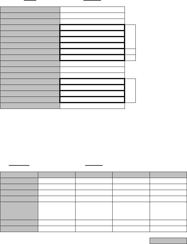
3.1 Equipment Setup
Note: Click on the “SET” button in Common area after every setting items has been entered.
Equipment Setup (Sample)
Redundancy Setting 1+1 (Hot Standby Term)
Inserted Module
INTFC Main (WORK) 2Port LAN PKG (e/w DS1) << Main (WORK) 2Port LAN PKG (e/w DS1)
INTFC Sub (PROT) Not Used << Sub (PROT) Not Used
XPIC Usage Not Used
APS Function Unavailable Available
Modulation Scheme QPSK
Transmission Capacity 48 [MB]
TX RF Frequency [MHz] 0.000
RX RF Frequency [MHz] 0.000
Frame ID ID1
TX Power Control MTPC ATPC
TRP Type Split Type
TX SW Type Mute RF SW Type
LAN Port Usage P1-2 Separated (Main+SC)
LAN Capacity1 P1 24Mbps
LAN Capacity2 P2 64kbps
--- TRP FREQ INFO ---
TX Start Frequency [MHz] 0.000
TX Stop Frequency [MHz] 0.000
RX Start Frequency [MHz] 0.000
RX Stop Frequency [MHz] 0.000
Frequency Step [MHz] 0.000
Shift Frequency [MHz] 0.000
Upper/Lower Upper
Sub Band
RF Frequency Type TX/RX
ROI-S07047 EQUIPMENT SETUP
-21-
Note: Item (*1) is selected when the INTFC Sub is applied.
Item (*2) is selected when the XPIC is applied.
Item (*3) is selected when the APS is applied.
1 Click on the menu button “Redundancy Setting” and select
corresponding item.
2 Setup can be performed by clicking the menu button to select
setup item from pull-down menu, clicking setting button or
entering values, then click on the “Set” button in Common area
to complete and confirm the setup procedure.
Redundancy Setting
INTFC Main (WORK)
Modulation Scheme
The modulation scheme must be setup with relative transmission capacity.
Refer to following Transmission Capacity item.
Redundancy Setting
INTFC Main (WORK)
INTFC Sub (PROT) (*1)
XPIC Usage (*2)
APS Function (*3)
Modulation Scheme
Transmission Capacity
Redundancy Setting 1+0 (Term)
1+1 (Hot Standby Term)
1+1 (Twinpath Term)
Inserted Module
INTFC Main (WORK) 2Port LAN PKG (e/w DS1) << Main (WORK) 2Port LAN PKG (e/w DS1)
Modulation Scheme QPSK
16QAM
64QAM
128QAM
EQUIPMENT SETUP ROI-S07047
-22-
Transmission Capacity
For QPSK Modulation Scheme, following pull-down menu is displayed.
For 16QAM Modulation Scheme, following pull-down menu is displayed.
For 64QAM Modulation Scheme, following menu is displayed.
For 128QAM Modulation Scheme, following menu is displayed.
Note: Select appropriate Modulation Scheme from pull-down menu for
the required transmission capacity from table below.
Transmission Capacity 48 [MB]
Transmission Capacity 156 [MB]
Transmission Capacity 42 [MB]
156 [MB]
Transmission Capacity 156 [MB]
RF CH Separation Modulation Scheme
QPSK 16QAM 64QAM 128QAM
10MHz −−
42 MB −
30MHz −− −
156 MB
40MHz 48 MB −156 MB −
50MHz −156 MB −−

ROI-S07047 EQUIPMENT SETUP
-23-
TX Frequency and RF Frequency for No.1 and No.2 are displayed in
Twinpath configuration.
RF Frequency
Notes: 1. Set different values for No.1 TX frequency and No.2 TX
frequency in the Twinpath configuration.
2. Depending on the TRP type, there are two modes for the RF
frequency setup.
1. When the transmitting frequency is set, the receiving
frequency is automatically assigned.
2. When the transmitting frequency is set, the receiving
frequency is automatically assigned or setting of it in
manual is also available. In this type, change the RF
frequency values which is automatically assigned.
The entered TX RF frequency value should be within the Start and
Stop frequency range of Sub-band which is indicated on the Name
Plate of each TRP. For details, refer to the Appendix RADIO
FREQUENCY PLAN FOR NLite N in Section 1.
Caution: For the 6 GHz band of NHG, the BPF of TX and RX of the
TRP are adjusted to each assigned frequency. Then, to
change the RF channel frequency over the variable range,
both BPFs replacement and LCT setup are required.
Frame ID
Note: Click menu button and set the frame ID in order to discriminate
the signal. As a signal with a different ID cannot be received, the
ID of the opposite station should be set the same. The number of
IDs which can be set up; ID1 through ID 32.
TX RF Frequency (No.1) [MHz]
TX RF Frequency (No.2) [MHz]
RX RF Frequency (No.1) [MHz]
RX RF Frequency (No.2) [MHz]
Frame ID (No.1)
Frame ID (No.2)
EQUIPMENT SETUP ROI-S07047
-24-
TX Power Control
Notes: 1. When the MTPC is selected, TX output level can be
controlled by 1 dB step within MTPC range.
When the ATPC is selected, TX output level is automatically
controlled by 1 dB step within ATPC range.
2. For the details of ATPC, refer to the Chapter 3.5.3
Automatic Transmitter Power Control in Section 2.
LAN Port Usage
Note: LAN Port Usage may be set when LAN is used. For the
details, refer to Appendix LAN INTFC (10/100BASE-
T(X)) Application and Setting in this Section IV.
Note: Settable parameters in the LAN Port Usage, depends on
the Modulation scheme and transmission capacity setting.
TX Power Control MTPC ATPC
LAN Port Usage (Main) Not Used
P1:P2=1:0
P1:P2=1:1
Best Effort
P1=Fixed/P2
P1-2 Shared/1Port Only (Main)
P1 Only (Main)
P1-2 Separated (Main)
P1-2 Separated (Main+WS)
P1-2 Separated (Main+SC)
ROI-S07047 EQUIPMENT SETUP
-25-
LAN Capacity1 Notes: 1. LAN Port1 Capacity may be set when LAN is used.
2. Selectable LAN Port1 capacity is depending on the main
signal transmission capacity. For the details, refer to
Appendix LAN INTFC (10/100BASE-T(X)) Application
and Setting in this Section IV.
(sample)
Note: Settable parameters in the LAN Port# Capacity, depends
on the settings in the Modulation scheme, Transmission
Capacity and LAN port Usage.
LAN Capacity2 Notes: 1.LAN Port2 Capacity may be set when LAN is used.
2.Selectable LAN Port2 Capacity is depending on the main
signal transmission capacity. For the details, refer to
Appendix LAN INTFC (10/100 BASE-T(X)) Application
and Setting in this Section IV.
(sample)
Note: Settable parameters in the LAN Port# Capacity, depends
on the settings in the Modulation scheme, Transmission
Capacity and LAN port Usage.
LAN Capacity1 P1 18Mbps
19.5Mbps
21Mbps
22.5Mbps
.
.
.
37.5Mbps
39Mbps
40.5Mbps
42Mbps
LAN Capacity2 P2 1.5Mbps (WS)

EQUIPMENT SETUP ROI-S07047
-26-
Possible Combinations for LAN Usage parameter settings are shown in below table.
Notes: *1: 1.5Mbps steps.
3 When every setup has been completed, confirm all setup values.
Modulation
Scheme Transmission
Capacity LAN Port Usage LAN Capacity1 LAN Capacity2
64QAM 42MB Not Used −−
P1-2 Shared/1Port Only (Main) 18Mbps − 42Mbps (*1) −
P1 Only (Main) 18Mbps −
42Mbps
P1-2 Separated (Main) 9Mbps −
21Mbps
P1-2 Separated (Main+WS) 18Mbps 1.5Mbps (WS)
42Mbps
P1-2 Separated (Main+SC) 18Mbps 64Kbps
42Mbps 128Kbps
256Kbps
QPSK 48MB Not Used −−
P1-2 Shared/1Port Only (Main) 24Mbps − 48Mbps (*1) −
P1 Only (Main) 24Mbps −
48Mbps
P1-2 Separated (Main) 12Mbps −
24Mbps
P1-2 Separated (Main+WS) 24Mbps 1.5Mbps (WS)
48Mbps
P1-2 Separated (Main+SC) 24Mbps 64Kbps
48Mbps 128Kbps
256Kbps
16QAM 156MB Not Used −−
64QAM P1:P2=1:0 100Mbps −
128QAM P1:P2=1:1 63Mbps −
75Mbps
Best Effort 150Mbps −
P1=FIXED/P2 100Mbps 1.5Mbps
26Mbps
50Mbps
P1-2 Separated (Main+WS) 100Mbps 1.5Mbps (WS)

ROI-S07047 EQUIPMENT SETUP
-27-
TRP FREQ INFO
4 Click on the “Set” button in Common area, then “OK” is
displayed in Progress area when the setup is properly executed.
Note: “NG” and error message are displayed in Progress State area,
if there is invalid setting in the Equipment Setup.
---TRP FREQ INFO---
TX Start Frequency (No.1) [MHz]
TX Stop Frequency (No.1) [MHz]
Frequency Step (No.1) [MHz]
Shift Frequency (No.1) [MHz]
Upper/Lower (No.1)
Sub Band (No.1)
TX Start Frequency (No.2) [MHz]
TX Stop Frequency (No.2) [MHz]
Frequency Step (No.2) [MHz]
Shift Frequency (No.2) [MHz]
Upper/Lower (No.2)
Sub Band (No.2)
INVENTORY ROI-S07047
-28-
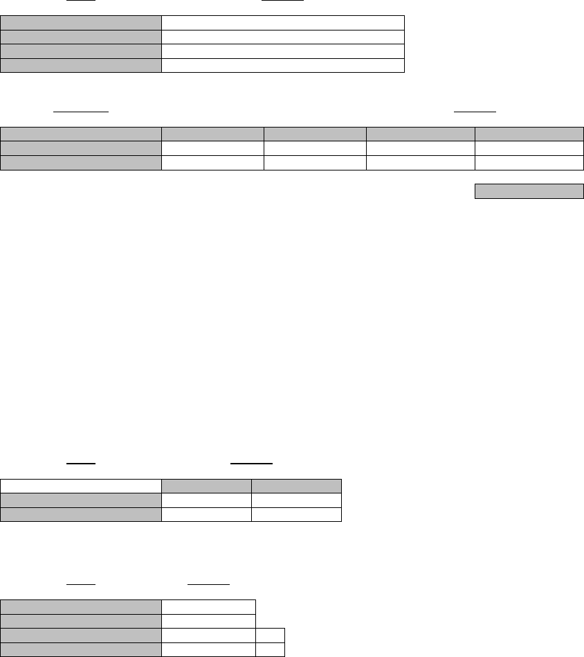
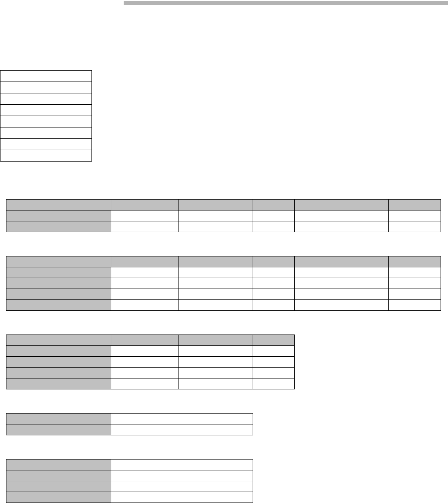
4. INVENTORY
1 Click on the “Inventory” button in “LCT Menu” then Inventory
Lists are displayed.
---TRP---
Package Name Code No. Serial No. Date H/W Version F/W Version
No.1 TRP NWA-034280-030 00004040 2008.10 4B0A 1.10
No.2 TRP NWA-034280-030 00004041 2008.10 4B0A 1.10
---MDP---
Package Name Code No. Serial No. Date H/W Version F/W Version
MODEM No.1 MODEM NWA-037060-004 00001171 2008.10 01.00
MODEM No.2 MODEM NWA-037060-004 00001172 2008.10 01.00
MDP(CTRL) CTRL NWA-036102-002 00001063 2008.12 01.00 1.0.0
INTFC(1) 2P LAN INTFC NWA-036103-001 00001031 2008.10 01.00
---FPGA---
Name Code No. Version
MODEM No.1 MODEM FPGA NWZ-028710-001 01.00
MODEM No.2 MODEM FPGA NWZ-028710-001 01.00
CTRL CTRL FPGA NWZ-028706-001 01.00
INTFC(1) 2P LAN FPGA NWZ-029791-001 01.00
---Modem Parameter Version---
No.1 01
No.2 01
---Network Properties---
IP Address 172.18.0.1
Subnet Mask 255.255.255.192
Default Gateway 192.168.100.1
MAC Address xx-xx-xx-xx-xx-xx
LCT Menu
Alarm/Status
Equipment Setup
Inventory
AUX I/O
Maintenance
Provisioning
Metering
PMON (History)
ROI-S07047 AUX. I/O
-29-
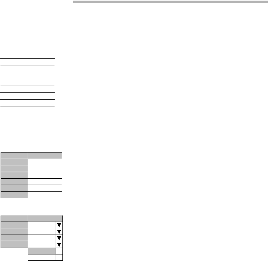
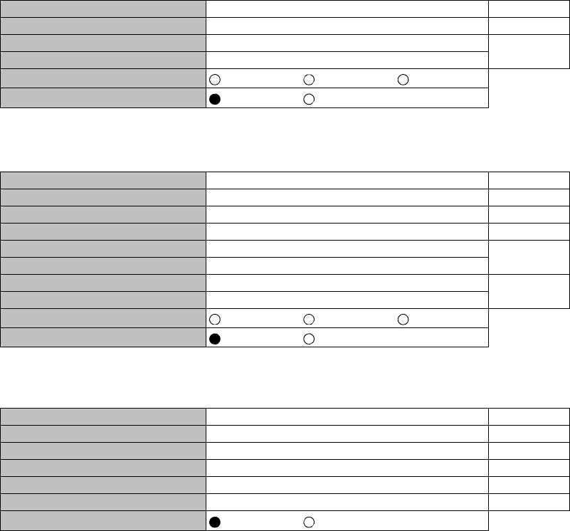
5. AUX. I/O
Six input (photocoupler) and six output (relay) are provided in the MDP
for external control and alarm outputs of Housekeeping and Cluster.
1 Click on the “AUX I/O” button in “LCT Menu”.
LCT Menu
Alarm/Status
Equipment Setup
Inventory
AUX I/O
Maintenance
Provisioning
Metering
PMON (History)
---Input---
Condition
Input1 Open
Input2 Open
Input3 Open
Input4 Open
Input5 Open
Input6 Open
---Output---
Value
Output1 Open
Output2 Open
Output3 Open
Output4 Open
Open
Close
2 Click menu button of required number of Output.
3 Select “Open” or “Close” to decide output mode to apply for
event output.
4 Click on the “Set” button in a Common area to execute setup.
Note: From Input 1 to Input 6 can be assigned to HK1 to HK6
input.
From Input 3 to Input 6 can be used to Cluster In4 to
Cluster In1.
From Output 1 to Output 4 can be assigned to HK Out1
to HK Out 4.
From Output 1 to Output 4 can be used to Cluster Out 1
to Cluster Out 4.
Cluster can be used up to 4 and for each Cluster In#
corresponding Cluster Out# should be set in the opposite
station.
5 Click on the “Set” button in Common area, then “OK” is
displayed in Progress area when the setup is properly executed.
Note: “NG” and error message are displayed in Progress State area, if
there is invalid setting in the Aux I/O.
MAINTENANCE ROI-S07047
-30-
6. MAINTENANCE
1 Click on the “Maintenance” button in “LCT Menu”.
2 Click on the “Maintenance1” pull-down menu to display control
items.
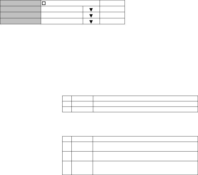
3 Click on the setting button “On” for Maintenance and Click on
the “Set” button, then value field turns to “On”.
Maintenance1 is described in Chapter 6.1 Maintenance1.
4 Click on the “Maintenance2” pull-down menu to upload/
download program file or reset CPU.
Maintenance2 is described in Chapter 6.2 Maintenance2.
LCT Menu
Alarm/Status
Equipment Setup
Inventory
AUX I/O
Maintenance
Provisioning
Metering
PMON (History)
Maintenance1
Maintenance2
---Maintenance1---
Item Value Setting
Maintenance On Off On Set
ROI-S07047 MAINTENANCE
-31-
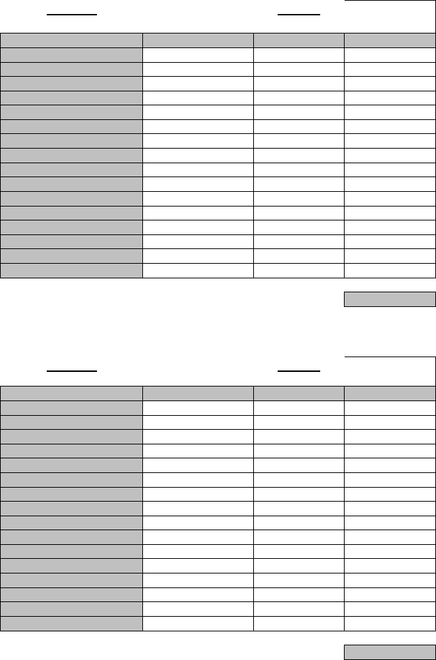
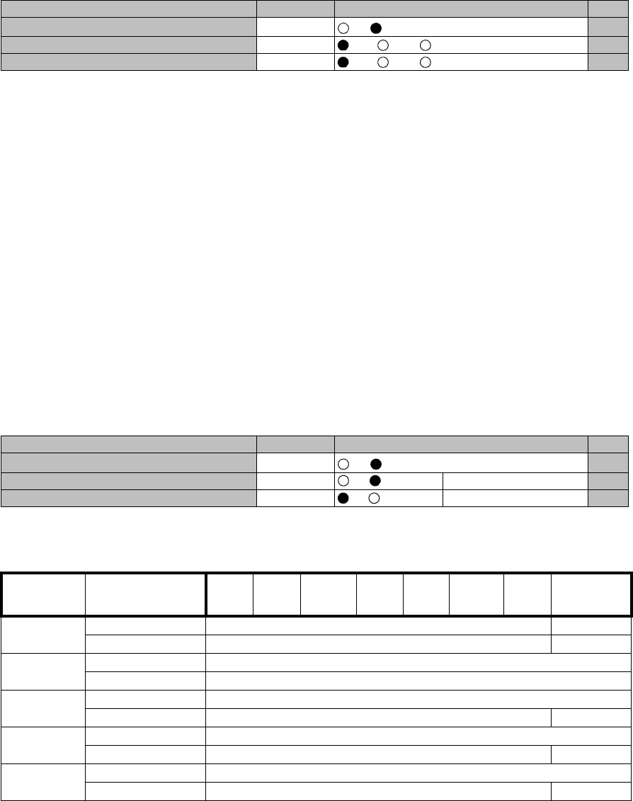
6.1 Maintenance1
Following control items are displayed in Maintenance1 menu (an example).
Note: Displayed items vary depending on system configuration.
No. 1 and No. 2 are displayed only in 1+1 system.
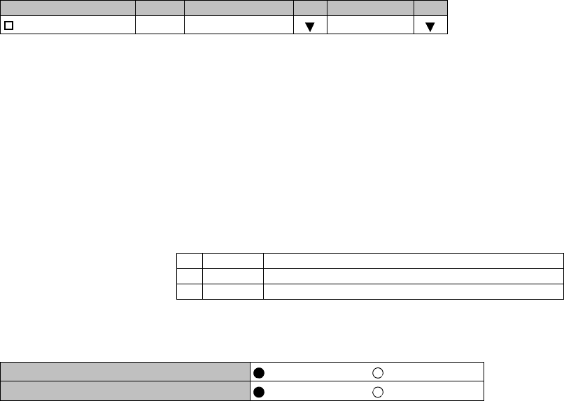
---Maintenance1---
Item Value Setting
Maintenance Off Off On Set
TX SW Manual Control Auto Auto No.1 No.2 Set
RX SW Manual Control Auto Auto No.1 No.2 Set
RX SW Maintenance Mode Manual
ATPC Manual Control (No.1) On Off On 0dB Set
ATPC Manual Control (No.2) On Off On 0dB Set
TX Mute Control (No.1) Off Off On Set
TX Mute Control (No.2) Off Off On Set
CW Control (No.1) Off Off On Set
CW Control (No.2) Off Off On Set
IF Loopback (No.1) Off Off On Set
IF Loopback (No.2) Off Off On Set
Main CH Loopback (Near End) Off Set
Main CH Loopback (Far End) Off Set
LAN Device Reset --- INTFC(1)-Port1 Set
--- Offline Maintenance ---
DADEAdjust --- DADE Offset DADE DADE Off Set
RF SUB Band select (No.1) --- A Set
RF SUB Band select (No.2) --- A Set
Antenna Alignment Mode (No.1) Off Off On Set
Antenna Alignment Mode (No.2) Off Off On Set
MAINTENANCE ROI-S07047
-32-
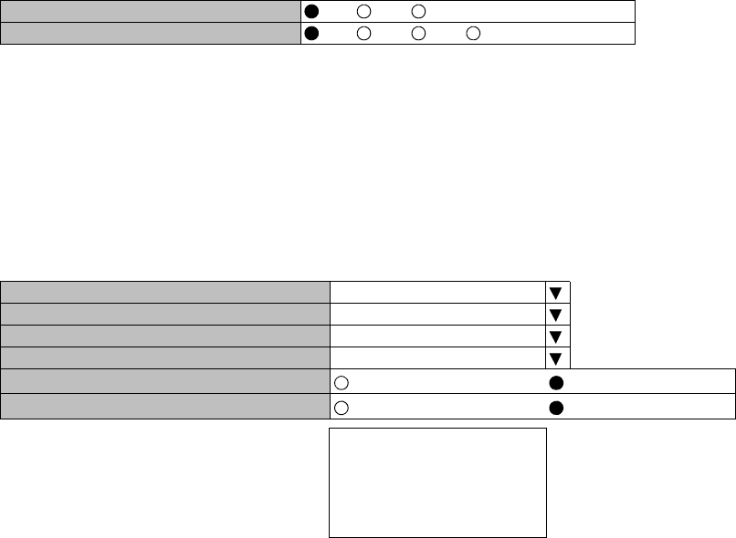
TX SW Manual Control
1 Click on the setting button “On” of the “Maintenance” and click
on the “Set” button, then value field of the Maintenance turns
from “Off” to “On”.
In Maintenance “On” mode, external parallel alarm outputs
excepts CPU and PS ALM are masked and automatic control is
inhibited.
Control operation using LCT must be performed in
Maintenance “On” condition.
2 Click on the setting button “Auto”, “No. 1” or “No. 2” TX SW
to select TX SW control mode and click on the “Set” button,
then the value field of the corresponding SW manual control
change to the selected mode.
Auto: Normal operation mode
No. 1 or No. 2: Manual control mode
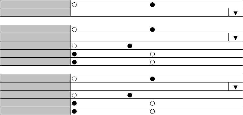
ATPC Manual Control
3 Click on the setting button “On” and enter attenuation value
within ATPC range, then click on the “Set” button.
---Maintenance1---
Item Value Setting
Maintenance On Off On Set
TX SW Manual Control Auto Auto No.1 No.2 Set
RX SW Manual Control Auto Auto No.1 No.2 Set
---Maintenance1---
Item Value Setting
Maintenance On Off On Set
ATPC Manual Control(No.1) On Off On [dB] Set
ATPC Manual Control(No.2) Off Off On Set
Modulation
Mode Frequency Band
(GHz) 5.8L6U611182324 38
QPSK ATPC Range 0 to 30 dB 0 to 25 dB
MTPC Range 0 to 30 dB 0 to 25 dB
16QAM ATPC Range 0 to 24 dB
MTPC Range 0 to 24 dB
32QAM ATPC Range 0 to 23 dB
MTPC Range 0 to 23 dB *10 to 23 dB
64QAM ATPC Range 0 to 20 dB
MTPC Range 0 to 20 dB *10 to 20 dB
128QAM ATPC Range 0 to 20 dB
MTPC Range 0 to 20 dB *10 to 20 dB
Note:*1 Additional attenuator from 0 to 5 dB can be added.
ROI-S07047 MAINTENANCE
-33-
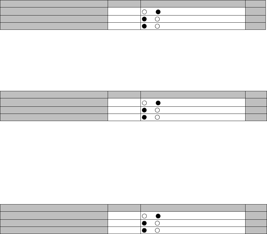
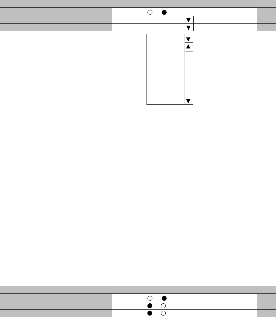
TX Mute Control
4 Click on the setting button “On” to select TX Mute Control.
5 Click on the “Set” button and the value field turns to “On”.
Caution: The control affects the radio link connection.
CW Control
6 Click on the setting button “On” to set CW Control ( ) and click
on the “Set” button, then value field turns to “On”.
Caution: The control affects the radio link connection.
Note: When set to CW Control “On”, unmodulated RF signal is
emitted.
IF Loopback
7 Click on the setting button “On” for the IF Loopback ( ) and
click on the “Set” button, then value field turns to “On”.
Caution: The control affects the radio link connection.
Note: The control applies to IF loopback in local MODEM.
---Maintenance1---
Item Value Setting
Maintenance On Off On Set
TX Mute Control (No.1) Off Off On Set
TX Mute Control (No.2) Off Off On Set
---Maintenance1---
Item Value Setting
Maintenance On Off On Set
CW Control (No.1) Off Off On Set
CW Control (No.2) Off Off On Set
---Maintenance1---
Item Value Setting
Maintenance On Off On Set
IF Loopback (No.1) Off Off On Set
IF Loopback (No.2) Off Off On Set

MAINTENANCE ROI-S07047
-34-
Main CH Loopback Control
8 Click on the “Select” button and click on the setting button
“On” of the required CH#(s) to be loop back and click the
“Execute” button.
For all DS1 channel loop back, click on the “Select” button
“On” in All Setting menu and click on the “Set” button.
Note: The control applies to loopback in each DS1 signal.
Caution: Far End Loopback control will be canceled when radio link
failure occurs under the control has been executed.
Note: The Control is available for DS1 channels set to used.
---Maintenance1---
Item Value Setting
Maintenance On Off On Set
Main CH Loopback (Near End) Off Select
Main CH Loopback (Far End) Off Select
---Main CH Loopback (Near End)---
CH01 Off Off On
CH02 Off Off On
CH03 Off Off On
CH04 Off Off On
CH05 Off Off On
CH06 Off Off On
CH07 Off Off On
CH08 Off Off On
CH09 Off Off On
CH10 Off Off On
CH11 Off Off On
CH12 Off Off On
CH13 Off Off On
CH14 Off Off On
CH15 Off Off On
CH16 Off Off On
All Setting
Off On Select Set Close
ROI-S07047 MAINTENANCE
-35-
Note: The Control is available for DS1 channels set to used.
LAN Device Reset
9 Select corresponding LAN port is to be reset from pull-down
menu, and click “Set” button.
---Main CH Loopback (Far End)---
CH01 Off Off On
CH02 Off Off On
CH03 Off Off On
CH04 Off Off On
CH05 Off Off On
CH06 Off Off On
CH07 Off Off On
CH08 Off Off On
CH09 Off Off On
CH10 Off Off On
CH11 Off Off On
CH12 Off Off On
CH13 Off Off On
CH14 Off Off On
CH15 Off Off On
CH16 Off Off On
All Setting
Off On Select Set Close
---Maintenance1---
Item Value Setting
Maintenance On Off On Set
LAN Device Reset --- INTFC(1)-Port1 Set
INTFC(1)-Port2

MAINTENANCE ROI-S07047
-36-
DADE Adjust
10 Click on the setting button “DADE”, “Offset DADE” or
“DADE Off” and click on the “Set” button.
Notes: 1.The DADE control applies in 1+1 configuration to adjust delay time for RX hitless
switching when the INTFC status is indicated Outphase.
2.The DADE adjustment is needed in initial lineup or when the IF CABLE is replaced. It
does not require any readjustment when the INTFC status is indicated In-phase. The
setting conditions are as follows:
DADE: Automatically adjust delay time based on either No.1 signal or No.2 signal
selected by the RX SW under the outphase condition of the INTFC status. The
DADE control is processed assuring no interruption of traffic.
Offset DADE:Automatically adjust delay time based on either No.1 signal or No.2 signal
selected by the RX SW under the outphase condition of the INTFC status.
Since the offset memory minimizes the latency delay, traffic interruption
occurs at that moment. This Offset DADE controls the delay time
difference to a minimum value than DADE control.
DADE off: Set when DADE function is not used.
---Offline Maintenance---
Item Value Setting
Maintenance On Off On Set
DADE Adjust --- DADE Offset DADE DADE Off Set
ROI-S07047 MAINTENANCE
-37-
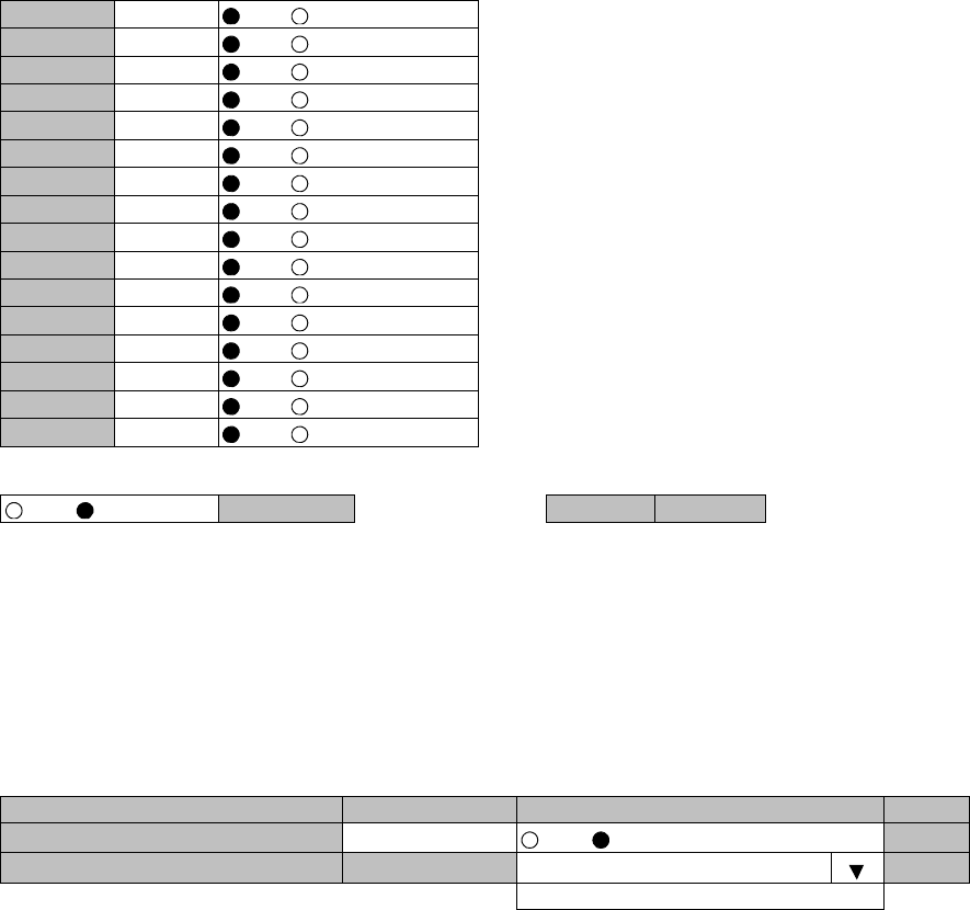
RF SUB Band Select
11 Click on the menu button, select required RF Sub-band from
pull-down menu, and click on the “Set” button.
Note: This is an offline menu item to be carried out after a Sub-band
BPF change in the TRP. Refer to Appendix Radio Frequency Plan
in section 1 for details of Sub-band versus Frequency Range.
Antenna Alignment Mode
12 Click on the setting button “On”, and click on the “Set” button,
to apply Antenna Alignment Mode ( ), then value field turns to
On.
Notes: 1. For the antenna orientation, set the TX power to the
required level by ATPC Manual Control or MTPC mode
at the opposite site.
2. The Antenna Alignment Mode is used for extending the
dynamic range of the OW/RX LEV MON unit. In order
to measure in high range of AGC V, it is mandatory
required to set Antenna Alignment Mode to ON. If not
set to ON, the indicated AGC voltage is not guaranteed
value.
3. No. 1 and No. 2 apply for 1+1 configuration.
---Offline Maintenance---
Item Value Setting
Maintenance On Off On Set
RF Sub Band Select(No.1) --- A Set
RF Sub Band Select(No.2) --- A Set
A
B
C
D
E
F
G
H
J
---Offline Maintenance---
Item Value Setting
Maintenance On Off On Set
Antenna Alignment Mode(No.1) Off Off On Set
Antenna Alignment Mode(No.2) Off Off On Set
MAINTENANCE ROI-S07047
-38-
6.2 Maintenance2
1 Click on the “Maintenance” button in “LCT Menu”.
2 Click on the “Maintenance1” pull-down menu.
3 Click on the setting button “On” for Maintenance item and click
on the “Set” button, then value field turns to “On”.
4 Click on the “Maintenance” button and select “Maintenance2”
pull-down menu.
Following control items are displayed in Main area.
Check that the “Maintenance” is “On” in the “Summary Status” area.
LCT Menu
Alarm/Status
Equipment Setup
Inventory
AUX I/O
Maintenance
Provisioning
Metering
PMON(History)
Maintenance1
Maintenance2
---Maintenance1---
Item Value Setting
Maintenance On Off On Set
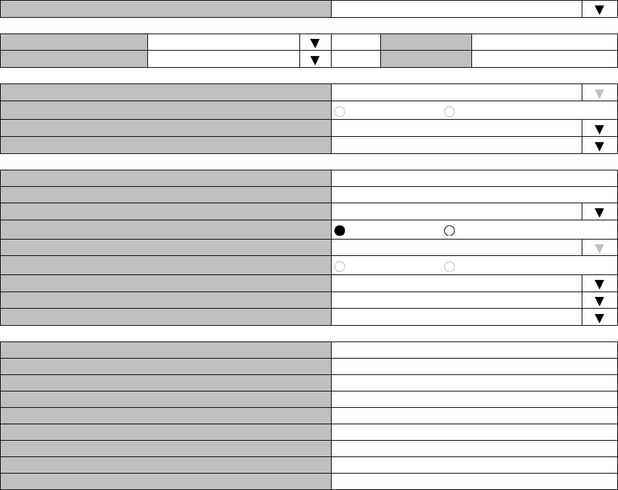
--- Maintenance2 ---
---Control---
CPU Reset
---Download---
Configuration File
Program File
Equipment Config. File
---Upload---
Configuration File
Equipment Config. File
---Date/Time---
Date/Time Setting
---Password---
Password Setting
---PMON Clear---
PMON Clear
ROI-S07047 MAINTENANCE
-39-
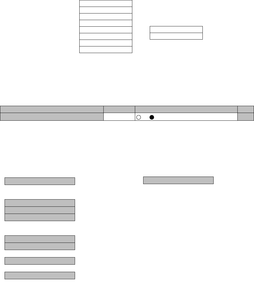
CPU Reset
5 Click on the “CPU Reset” button.
6 Click on the control button “CTRL” for MDP or “TRP” and
“No. 1 or No. 2” (in 1+1 TRP only), and click “Execute” button
in CPU Reset dialog box.
Caution: The control affects the radio link connection.
Check “with ROM (Program) Switching” check box when the program
file for “CTRL” is newly down loaded and existing program file will be
replaced with new one.
Note: When Click on the “Execute” button to reset CPU of the “CTRL”,
then CTRL restarts, the LCT is disconnected.
Access the LCT to the NLite N from the beginning.
7 Click on the “Close” button to dismiss the “CPU Reset” dialog
box.
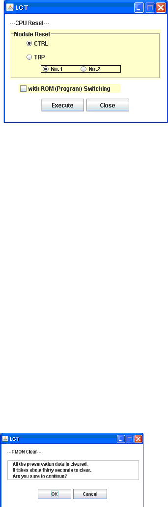
PMON Clear
8 Click on the “PMON Clear” button.
Perform this operation when beginning the service operation to
delete all PMON and RMON data that were produced in
installation.
9 Click on the “Execute” button.
10 Click on the “Close” button when “OK” is displayed in Progress
area.
MAINTENANCE ROI-S07047
-40-
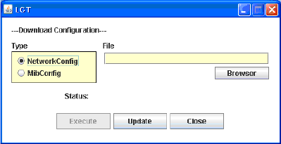
Download Configuration File
11 Click on the “Configuration File” button “Download” menu.
12 Select the file Type “Net Work Config” or “Mib Config”.
13 Enter the location of the Configuration file in File field or click
on the “Browser” button to display location in the hard disk or
floppy disk.
14 Click on the “Execute” button to start down load.
Caution: The control affects the radio link connection.
Caution: While data is being transmitted, do not remove the
USB cable connecting the MDP with the PC.
15 After download has been completed, click on the “Update”
button for the corresponding configuration will be operated with
updated file.
16 Click on the “Close” button to dismiss the “Download
Configuration” dialog box.
ROI-S07047 MAINTENANCE
-41-
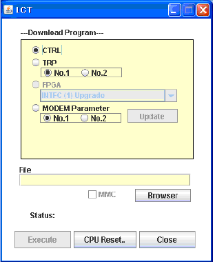
Download Program
17 Click on the “Program File” of “Download” menu.
18 Click on the “CTRL”, “TRP” or “MODEM Parameter” and
corresponding Sub-item control button.
19 Enter the location of the Program File in File field or click on
the “Browser” to display location in the hard disk.
20 Click on the “Execute” button to start the download of program
file.
Caution: While data is being transmitted, do not remove the
USB cable connecting the MDP with the PC.
21 After download of the CTRL Package has been completed, the
CPU Reset dialog box appears, then click on the “CPU Reset”
button.
Caution: The control affects the radio link connection.
22 Select on the control button “CTRL” for MDP, check “with
ROM (Program) Switching” check box and click “Execute”
button in CPU Reset dialog box.
23 Click on the “Close” button to dismiss the “Download
Configuration” dialog box.
MAINTENANCE ROI-S07047
-42-
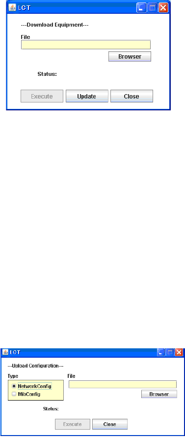
Download Equipment
24 Click on the “Equipment Config File” of “Download” menu.
25 Enter the location of the “Equipment Config File” in File field
or click on the “Browser” button to display location in the hard
disk, floppy disk or MMC, click on the “Execute” button to start
the download.
Caution: While data is being transmitted, do not remove the
USB cable connecting the MDP with the PC.
26 After download has been completed, click on the “Update”
button for the CTRL will be operated with updated config file.
Caution: The control affects the radio link connection.
27 Click on the “Close” button to dismiss the “Download
Equipment” dialog box.
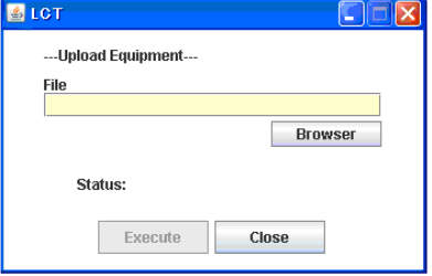
Upload Configuration File
28 Click on the “Configuration File” of “Upload” menu.
29 Select the file Type “Net Work Config” or “Mib Config”.
30 Enter the directory of the file name where the uploaded file will
be saved.
31 Click on the “Execute” button to start the uploading.
Caution: While data is being transmitted, do not remove the
USB cable connecting the MDP with the PC.
ROI-S07047 MAINTENANCE
-43-
32 After Configuration File has been uploaded, click on the
“Close” button to dismiss the “Upload Configuration” dialog
box.
Upload Equipment Config File
33 Click on the “Equipment Config File” of “Upload” menu.
34 Enter the directory of the file name where the uploaded file will
be saved.
35 Click on the “Execute” button to start the uploading.
Caution: While data is being transmitted, do not remove the
USB cable connecting the MDP with the PC.
36 After Equipment Config File has been uploaded, click on the
“Close” button to dismiss the “Upload Equipment” dialog box.
MAINTENANCE ROI-S07047
-44-
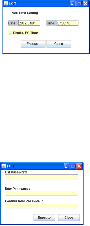
Date/Time Setting
37 Click on the “Date/Time Setting” button of “Network” menu.
38 Click on the “Display PC Time” button, then the PC “Date”and
“Time” are indicated in the fields.
39 Click on the “Execute” button, then Date/Time setting for the
CTRL is performed.
40 Click on the “Close” button to dismiss the “Date/Time Setting”
dialog box.
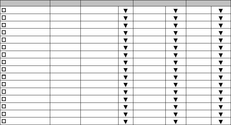
Password Setting
41 Click on the “Password Setting” button.
42 Enter the current password in “Old Password” entry field.
43 Enter the new password in “New Password” entry field.
44 Enter the same password written in “New Password” entry field
in “Confirm new password” entry field.
45 Click on the “OK” button after confirmed “New Password” and
“Confirm new password”.
46 Click on the Maintenance1, set Maintenance “Off” and click on
the “Set” button, then value field turns to “Off”.

ROI-S07047 PROVISIONING
-45-
7. PROVISIONING
1 Click on the “Provisioning” button in the “LCT Menu”.
2 Continue to Chapter 7.1 Provisioning Setup.
LCT Menu
Alarm/Status
Equipment Setup
Inventory
AUX I/O
Maintenance
Provisioning
Metering
PMON (History)
When Click on the “Provisioning” button in “LCT Menu”, Provisioning
setup items are displayed in Main area.
Notes:1. Provisioning setup must be performed after every setup
items of the “Equipment Setup” has been completed. If it
has any pending item or improper setting of the
Equipment Setup, the “Provisioning Setup” will not be
completed.
2. When setting or changing Equipment Setup, check the
setting values of all the Provisioning items.
PROVISIONING ROI-S07047
-46-
7.1 Provisioning Setup
Note: To execute setup for each item, every time Click on the “Set” button in common area.
DS1 Setting
1 Click on the “DS1 Setting” button in Provisioning menu.
2 Select CH Usage, Line Length, Bipolar Code and Frame Format
for each channel. Select the CH to be used by placing a check
mark on the “CH Usage” check box.
---DS1 Setting---
CH Usage Status Line Length Bipolar Code Frame Format
CH01 0-133ft(0-40m) B8ZS Unframed
CH02 0-133ft(0-40m) B8ZS Unframed
CH03 0-133ft(0-40m) B8ZS Unframed
CH04 0-133ft(0-40m) B8ZS Unframed
CH05 0-133ft(0-40m) B8ZS Unframed
CH06 0-133ft(0-40m) B8ZS Unframed
CH07 0-133ft(0-40m) B8ZS Unframed
CH08 0-133ft(0-40m) B8ZS Unframed
CH09 0-133ft(0-40m) B8ZS Unframed
CH10 0-133ft(0-40m) B8ZS Unframed
CH11 0-133ft(0-40m) B8ZS Unframed
CH12 0-133ft(0-40m) B8ZS Unframed
CH13 0-133ft(0-40m) B8ZS Unframed
CH14 0-133ft(0-40m) B8ZS Unframed
CH15 0-133ft(0-40m) B8ZS Unframed
CH16 0-133ft(0-40m) B8ZS Unframed
ROI-S07047 PROVISIONING
-47-
Note: DS1 Channel numbers and LAN shares with DS1 vary
depending on the Transmission Capacity and LAN Port1
Capacity and LAN Port2 Capacity which are set in
“Equipment Setup”.
Note: 1. Line Length
Setting is based on the cable length of the DS1 signal.
2. Bipolar Code
Set the DS1 signal Line Code. Refer to the table below.
3. Frame Format
Set the DS1 signal Frame Format. Refer to the table below.
All Setting
CH Usage All Set Select
Line Length 0-133ft(0-40m) Select
Bipolar Code B8ZS Select
Frame Format Unframed Select
No. Mode Descriptions
1 AMI Alternate mark inversion
2 B8ZS Bipolar with eight zero substitution
No. Mode Descriptions
1Unframed
Unframed
Not applies frame structure.
2SF Superframe format
A superframe consists of twelve consecutive frames.
3ESF Extended superframe format
An extended superframe consists of twenty-four
consecutive frames.

PROVISIONING ROI-S07047
-48-
3 Click on the either setting button for every items shown below.
Notes: 1. CH Usage Error Report:
Report:
When a DS1 signal is applied to a channel which is set as “not used”, an
alarm is displayed.
Not Report:
Even when a DS1 signal is applied to a channel which is set as “not used”,
an alarm is not displayed.
2. AIS Activation Condition
LOF + High BER:
When the LOF ALM or High BER has occurred, DS1 AIS signal is
generated.
LOF:
When the LOF ALM has occurred, DS1 AIS signal is generated.
3. AIS Generated (Received) Report
AIS Generated (Received) Report sets whether AIS Generated (Received)
for DS1 is reported or not reported.
---Other Setting---
CH Usage Error Report Not Report Report
AIS Activation Condition LOF+High BER LOF
AIS Received Report Not Report Report
AIS Received Condition Alarm Status
AIS Generated Report Not Report Report
ROI-S07047 PROVISIONING
-49-
WS Setting
4 Click on the “WS Setting” button in Provisioning menu.
5 Select CH Usage, Line Length and Bipolar Code for each
channel. Select the CH to be used by placing a check mark on
the “CH Usage” check box.
---WS Setting---
Note: DS1 Wayside Channel numbers and LAN shares with DS1
Wayside vary depending on the Transmission Capacity and LAN
Port1 Capacity and LAN Port2 Capacity which are set in
“Equipment Setup”.
Note: 1. Line Length
etting depends on the cable length of the DS1 Wayside signal
2. Bipolar code
Set the DS1 wayside signal Line code. Refer to the table below.
6 Click on the either setting button for every items shown below.
Note: AIS Generated (Received) Report
AIS Generated (Received) Report sets whether AIS Generated
(Received) for DS1 Wayside is reported or not reported.
CH Usage Status Line Length Bipolar Code
CH01 0-133ft(0-40m) B8ZS
No. Mode Descriptions
1 AMI Alternate mark inversion
2 B8ZS Bipolar with eight zero substitution
---Other Setting---
AIS Received Report Not Report Report
AIS Generated Report Not Report Report
PROVISIONING ROI-S07047
-50-
BER Threshold
7 Click on the “BER Threshold Setting” sub-menu button in
“Provisioning”.
8 Click on the control button of required BER threshold level for
“High BER Threshold” and “LOW BER Threshold”.
SC Assignment
9 Click on the “SC Assignment” button in “Provisioning” menu
particulars.
10 Click on the menu button of each RS-232C( ) and V-11-( ) and
select item from pull down menu to assign a SC or select Not
used.
---BER Threshold Setting---
High BER Threshold 1E-3 1E-4 1E-5
Low BER Threshold 1E-6 1E-7 1E-8 1E-9
---SC Assignment---
RS-232C-1 SC1
RS-232C-2 SC2
V-11-1 SC3
V-11-2 SC4
V-11-1 Direction Setting Co-directional Contra-directional
V-11-2 Direction Setting Co-directional Contra-directional
Not Used
SC1
SC2
SC3
SC4

ROI-S07047 PROVISIONING
-51-
LAN Port Setting
11 Click on the “LAN Port Setting” sub-menu button in
“Provisioning”.
12 Click on the setting button of Switching Function.
13 Click on the setting button of Port ( ) usage.
Note: For the details of setup item of the LAN PORT USAGE, refer to the LAN INTERFACE (10/
100BASE T(X) Application and Setting in Section IV.
1. Switching function:
This is a setup if the Switch Hub is used between Port1 and Port2 or it does
not used when the signal domain of the radio link shares with the Port1 and
Port2 (It can be used only Shared Mode, or not be used in the Separated
Mode of the Port1 and Port2.)
Disabled: No use of Ports for the Switch Hub. (default value)
Enabled: Use of Ports for the Switch Hub.
2. 1.5M Framing:
When the bandwidth of LAN signal is set to 1.5M, simple 1.5M framing of
ANSI T1.403 can be applied to the output data of the radio side. This function
can be used when the LAN signal is to be connected via opposite radio in the
DS1 network.
3. Port Usage: Use of LAN Port or no use. (default value is Used)
4. Speed & Duplex:
Setting for Port speed and Duplex.
Referring to the following table, set the Port mode according to the
associated equipment which it is to be connected. Note that if the setting
mode differs from associated equipment, it may be caused performance
degradation or link loss. (default value is AUTONEG (Auto MDI/MDIX))
5. Flow Control:
On: Effective flow control (default value is On)
Off: Non-effective flow control.
No. Mode Descriptions
1Unframed Unframed
Not applies frame structure. Every 1.544Mbps data are
treated in the LAN data domain.
2SF Superframe format
A superframe consists of twelve consecutive frames.
Applies frame structure is treated as LAN data domain.
3ESF
Extended superframe format
An extended superframe consists of twenty-four
consecutive frames. Applies frame structure is treated as
LAN data domain.

PROVISIONING ROI-S07047
-52-
6. Collision Report:
In HALF-Duplex mode, it is selected that is reported or not reported about
collision conditions at each port. (default value is Not Report)
7. Link Loss Forwarding:
Setting of the Link Loss Forwarding mode is effective or no effective. (See
Link Loss Forwarding description in the Section II Operation) (default value
is Disabled)
√ : A setup is possible.
Note: *: MDI/MDI-X is selected according to the cable type or terminal
type to be used (straight or cross type).
External Equipment
Setting Position
Auto Negotiation
10BASE-T/Half Duplex
10BASE-T/Full Duplex
100BASE-TX/Half Duplex
100BASE-TX/Full Duplex
10BASE-T/Half (FIX)
100BASE-TX/Half (FIX)
MDP Port
Setting Position
Auto Negotiation (Auto MDI/MDI-X) √⎯⎯⎯⎯ √√
10BASE-T/Half Duplex (MDI/MDI-X*) ⎯√⎯⎯⎯⎯⎯
10BASE-T/Full Duplex (MDI/MDI-X*) ⎯⎯ √⎯⎯⎯⎯
100BASE-TX/Half Duplex (MDI/MDI-X*) ⎯⎯⎯ √⎯⎯⎯
100BASE-TX/Full Duplex (MDI/MDI-X*) ⎯⎯⎯⎯ √⎯⎯
ROI-S07047 PROVISIONING
-53-
--- LAN Port Setting ---
Switching Function Disabled Enabled
1.5M Framing Unframed
--- Port1 ---
Port Usage Not Used Used
Speed & Duplex AUTONEG (Auto-MDI/MDIX)
Flow Control Off On
Collision Report Not Report Report
Link Loss Forwarding Disabled Enabled
--- Port2 ---
Port Usage Not Used Used
Speed & Duplex AUTONEG (Auto-MDI/MDIX)
Flow Control Off On
Collision Report Not Report Report
Link Loss Forwarding Disabled Enabled
PROVISIONING ROI-S07047
-54-
TX Power Control
14 Click on the “TX Power Control” sub-menu button in
“Provisioning”.
15 Enter required values in each control entry field within specified
range.
(1) ATPC mode in 1+0 or Hot Standby configuration
(2) ATPC mode in Twinpath configuration
(3) MTPC mode in Twinpath configuration
Notes: 1. No.1 and No.2 are indicated in Twinpath configuration only.
2. For Hot Standby configuration, the TX Power Control effects both
No. 1 and No. 2 TRPs.
3. ATPC/MTPC Range varies depending on RF frequency band and
modulation scheme.
4. ATPC Threshold level Range varies depending on modulation
scheme and RF signal channel separation.
5. ATPC power mode: (output power when ATPC control signal fails)
Hold: Maintain the current TX output level at the time of the
ATPC is malfunction.
---TX Power Control--- Range
ATPC Threshold Level [dBm] -60 -80 to -30
Additional ATT [dB] 0 0 to 5
ATPC Range(MAX) [dB] 0 -30 to 0
ATPC Range(MIN) [dB] -30
ATPC Power Mode Hold MAX MIN
COMM Alarm Mode *6 Mute Hold
---TX Power Control--- Range
ATPC Threshold Level (No.1) [dBm] -60 -80 to -30
ATPC Threshold Level (No.2) [dBm] -60 -80 to -30
Additional ATT (No.1) [dB] 0 0 to 5
Additional ATT (No.2) [dB] 0 0 to 5
ATPC Range(MAX) (No.1) [dB] 0 -30 to 0
ATPC Range(MIN) (No.1) [dB] -30
ATPC Range(MAX) (No.2) [dB] 0 -30 to 0
ATPC Range(MIN) (No.2) [dB] -30
ATPC Power Mode Hold MAX MIN
COMM Alarm Mode *6 Mute Hold
---TX Power Control--- Range
MTPC TX Power (No.1) [dB] 0 -30 to 0
MTPC TX Power (No.2) [dB] 0 -30 to 0
ATPC Threshold Level (No.1) [dBm] -60 -80 to -30
ATPC Threshold Level (No.2) [dBm] -60 -80 to -30
Additional ATT (No.1) [dB] 0 0 to 5
Additional ATT (No.2) [dB] 0 0 to 5
COMM Alarm Mode *6 Mute Hold

ROI-S07047 PROVISIONING
-55-
MAX: Maintain the ATPC maximum TX output level at the time
of the ATPC is malfunction.
Recommend to set MAX mode when norminal receiving
signal level is the out of ATPC range.
MIN: Maintain the ATPC minimum TX output level at the time
of the ATPC is malfunction.
Never beyond –20 dBm of receiver input level in any
settings.
6. Select TRP output powermode when the communication fails
between MDP and TRP due to some problems.
When Mute is set, the TRP output power will be muted.
(Default)
When Hold is set, the TRP output power will be hold.
(Should consider neighboring system)
Condition for TX/RX SW (only for 1+1 configuration)
16 Click on the “Condition for TX/RX SW” sub-menu button in
“Provisioning”.
17 Click on the control button of required control mode for the TX
SW and the RX SW.
Notes: 1. TX SW control mode is applied only for Hot Standby
configuration.
2. For TX and RX SW Priority, select Non Priority for Non-
reverting operation when TX or RX alarm condition is
restored.
3. “TX SW Lock in Usage” locks the TX switching to prevent
frequent switching changes.
4. “Reverse function Usage”. Carry out TX Switching upon
receiving a request from the opposite MDP, when it detects
abnormal receiving condition.
The TXSW request from own station has higher priority than
above switching operation.
5. Manual mode of RX SW Maintenance Mode disables the RX
SW operation when either No. 1 or No. 2 RX route is in alarm
status.
6. Forced mode of RX SW Maintenance Mode enables the RX
SW operation even though either or both No.1 and No.2 RX
route is in alarm status.
----Condition for TX/RX SW---
TX SW Priority Non Priority Priority No.1
TX SW Lock in Usage Not Used Used
TX SW Reverse Function Usage Not Used Used
RX SW Priority Non Priority Priority No.1
RX SW Maintenance Mode Manual Forced
RX SW Condition-Early Warning Included EW Excluded EW
PROVISIONING ROI-S07047
-56-
7. RX SW Condition_early warning: whether to consider early
warning BER as a condition for RX switching or not.
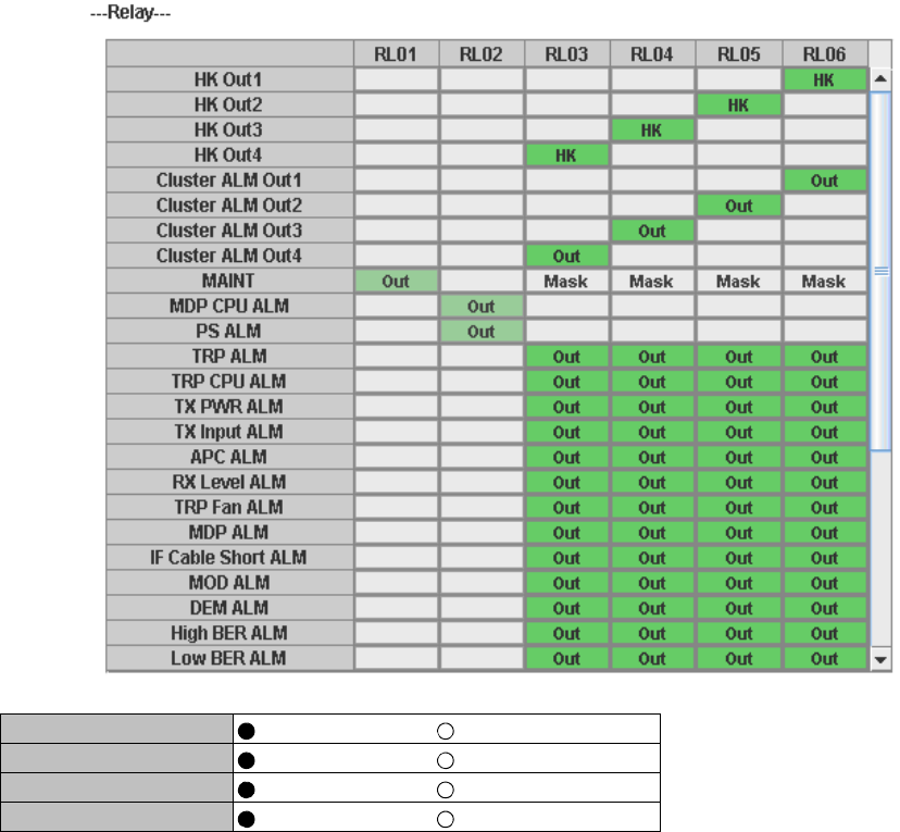
18 Click on the “Relay Setting” sub-menu button in “Provisioning”.
19 Click on the setting box crossed corresponding item and RL.
Note: Display or non-display of Relay Setting items depends on Redundancy Setting.
Example:When setting to (1+0) mode, the items of No.2 side become non-display.
At this moment, contact information (“Out”) set so far are all cleared regarding
the items which become non-display due to the setting change. Accordingly,
users are required to set the setting information again when these items are
redisplayed after setting change.
Note: When the selected item for RL assignment is invalid, “NG” and
error message are displayed in Progress State area.
Cluster1 Input Disabled Enabled
Cluster2 Input Disabled Enabled
Cluster3 Input Disabled Enabled
Cluster4 Input Disabled Enabled

ROI-S07047 PROVISIONING
-57-
The following are assignable items for external Relay output.
HK Out1
HK Out2
HK Out3
HK Out4
Cluster ALM Out1
Cluster ALM Out2
Cluster ALM Out3
Cluster ALM Out4
MAINT
MDP CPU ALM
PS ALM (No.1)
PS ALM (No.2)
TRP ALM (No.1)
TRP ALM (No.2)
TRP CPU ALM (No.1)
TRP CPU ALM (No.2)
TX PWR ALM (No.1)
TX PWR ALM (No.2)
TX Input ALM (No.1)
TX Input ALM (No.2)
APC ALM (No.1)
APC ALM (No.2)
RX Level ALM (No.1)
RX Level ALM (No.2)
MDP ALM
IF Cable Short ALM (No.1)
IF Cable Short ALM (No.2)
MOD ALM (No.1)
MOD ALM (No.2)
DEM ALM (No.1)
DEM ALM (No.2)
High BER ALM (No.1)
High BER ALM (No.2)
Low BER ALM (No.1)
Low BER ALM (No.2)
LOF (No.1)
LOF (No.2)
Input LOS 01-28
AIS Received 01-28
AIS Generated 01-28
CH Usage Error 01-28
LAN Link ALM
WS Input ALM
SC LAN Link ALM
PROVISIONING ROI-S07047
-58-
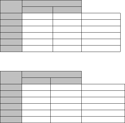
TCN Threshold (15min 1day)
20 Click on the “TCN Threshold (15min)” or “TCN Threshold
(1day)” or sub-menu button in “Provisioning”.
21 Enter required values in threshold OCR (Alarm Occur) and
RCVR (Alarm Recover) fields of performance item.
Note: Do not mistake the setting such as the OCR ≤ RCVR or RCVR = 0.
Notes: OFS: Out of Frame Second
UAS: Unavailable Second
ES : Errored Second
SES : Severely Errored Second
BBE: Background Block Errors
SEP: Severely Errored Period
----TCN Threshold (15min)---
Total
Occur Recover Range
OFS 900 90 0 to 900
UAS 900 90 0 to 900
ES 900 90 0 to 900
SES 900 90 0 to 900
BBE 2970 300 0 to 1031400
SEP 900 90 0 to 900
----TCN Threshold (1day)---
Total
Occur Recover Range
OFS 65534 650 0 to 86400
UAS 65534 650 0 to 86400
ES 65534 650 0 to 86400
SES 65534 650 0 to 86400
BBE 285120 28520 0 to 99014400
SEP 65534 650 0 to 86400

ROI-S07047 PROVISIONING
-59-
--- CSU Threshold (15min) ---
Frame Incoming Incoming Outgoing
Format CV-L CV-P CV-P
Occur Recover Occur Recover Occur Recover
CH01 SF 416880000 41688000 2160000 216000 2160000 216000
CH02 SF 416880000 41688000 2160000 216000 2160000 216000
CH03 SF 416880000 41688000 2160000 216000 2160000 216000
CH04 SF 416880000 41688000 2160000 216000 2160000 216000
CH05 SF 416880000 41688000 2160000 216000 2160000 216000
CH06 ESF 416880000 41688000 630000 63000 630000 63000
CH07 ESF 416880000 41688000 630000 63000 630000 63000
CH08 ESF 416880000 41688000 630000 63000 630000 63000
CH09 ESF 416880000 41688000 630000 63000 630000 63000
CH10 ESF 416880000 41688000 630000 63000 630000 63000
CH11 416880000 41688000
CH12 416880000 41688000
CH13 416880000 41688000
CH14 416880000 41688000
CH15 416880000 41688000
CH16 416880000 41688000
Range 0 to 1389600000 SF: 0 to 7200000
ESF: 0 to 2100000

PROVISIONING ROI-S07047
-60-
Notes:1. CV-L: The number counted depends on the bipolar code
setting.
AMI: count and accumulate BPV (bipolar Violations)
B8ZS: count and accumulate both BPV (bipolar Violations)
and EXZ (Excessive Zeros)
2. CV-P: The number counted depends on the Frame Format
setting.
Unframed:
not counted
SF (Super Frame):
count and accumulate frame bit errors
ESF (Extended Super Frame) count and accumulate frame bit
errors and CRC errors.
--- CSU Threshold (1day) ---
Frame Incoming Incoming Outgoing
Format CV-L CV-P CV-P
Occur Recover Occur Recover Occur Recover
CH01 SF 40020480000 4002048000 207360000 20736000 207360000 20736000
CH02 SF 40020480000 4002048000 207360000 20736000 207360000 20736000
CH03 SF 40020480000 4002048000 207360000 20736000 207360000 20736000
CH04 SF 40020480000 4002048000 207360000 20736000 207360000 20736000
CH05 SF 40020480000 4002048000 207360000 20736000 207360000 20736000
CH06 ESF 40020480000 4002048000 60480000 6048000 60480000 6048000
CH07 ESF 40020480000 4002048000 60480000 6048000 60480000 6048000
CH08 ESF 40020480000 4002048000 60480000 6048000 60480000 6048000
CH09 ESF 40020480000 4002048000 60480000 6048000 60480000 6048000
CH10 ESF 40020480000 4002048000 60480000 6048000 60480000 6048000
CH11 40020480000 4002048000
CH12 40020480000 4002048000
CH13 40020480000 4002048000
CH14 40020480000 4002048000
CH15 40020480000 4002048000
CH16 40020480000 4002048000
Range 0 to 133401600000 SF: 0 to 691200000
ESF: 0 to 201600000

ROI-S07047 PROVISIONING
-61-
PMON Select
22 Click on the “PMON Select” sub-menu button in
“Provisioning”.
23 Enter required “RX Level TCN Threshold” level in text field.
24 Click on the control button of “SES Activation Condition”.
---PMON Select---
RX Level TCN Threshold [dBm] −82.0
SES Activation Condition 30[%] 15[%]

PROVISIONING ROI-S07047
-62-
In-band Loopback Setting
25 Click on the “In-band Loopback Setting” button in Provisioning
menu.
26 Click on the either setting button for every items shown below.
Note: 1. Mode
Set the in-band loop back Mode.
Disable: Loopback Mode disabled
Enable(Code):
Execute Loopback when receiving the Activation code
over (in) the DS1 signal and release the loopback
when receiving the Deactivation code.
Enable (Messages):
Execute Loopback when receiving the Activate
Message over (in) the DS1 signal, and release the
loopback when receiving the deactivation message.
2. Activation code
When the selected Mode is Enable(code), set the length of the
code in bits and its specific value to execute the loopback. Do
not set the value of the code to all “0” or all “1”.
3. Deactivation code
When the selected Mode is Enable (Code), set the length of the
code in bits and its specific value to release the Loopback. Do
not set the value of the code to all “0” or all “1”.
4. Activation
messageWhen the selected Mode is Enable (messages), set the
message to execute the Loopback. Do not set the value of the
code to all “0” or all “1”.
5. Deactivation Message
When the selected Mode is Enable (messages), set the message
to release the Loopback. Do not set the value of the code to all
“0” or all “1”.
--- Near End ---
Item Value Setting
Mode Disable Disable
Activation Code 00001 5bit 00001
Deactivation Code 001 3bit 001
Activation Messages 11111111 01110000 11111111 0??????0 111000
Deactivation Messages 11111111 00011100 11111111 0??????0 001110
<< Direction of Transmission
ROI-S07047 PROVISIONING
-63-
Note: When the frame format is set to “ESF”, Far End Loopback can
be executed. Frame format is set from the provisioning “DS1
Setting”.
Note: 1. Mode
Set the in-band loop back Mode.
Disable: Loopback Mode disabled
Enable(message):
Execute Loopback when receiving the Activation
message over (in) the DS1 signal and release the
loopback when receiving the Deactivation Message.
2. Activation code
When the selected Mode is Enable(messages), enter the 6bit
value to be inserted in the place of “?” in the 16bit Activation
Message to execute the loopback. Do not set the value of the
code to all “0” or all “1”.
3. Deactivation code
When the selected Mode is Enable (Message), enter the 6bit
value to be inserted in the place of “?” in the 16bit
Deactivation Message to release the loopback. Do not set the
value of the message to all “0” or all “1”.
Note. When the Mode setting is Enable (Code), and the Activation code
bit length and its value is the same as that set in the deactivation
code, “NG” is indicated at “Code/Messages check status”
display. Correct the values and Set again to clear the “NG”
indication.
Note: When the Mode setting is Enable (Messages) and the Near End/
Far End Activation and deactivation message is the same, “NG”
is indicated at “Code/Message check status” display. Correct the
values and Set again to clear the “NG” indication.
--- Far End ---
Item Value Setting
Mode Disable Disable
Activation Messages 11111111 00000100 11111111 0??????0 000010
Deactivation Messages 11111111 00111000 11111111 0??????0 011100
<< Direction of Transmission
--- Code/Messages Check Status ---
CH 01 02 03 04 05 06 07 08 09 10 11 12 13 14 15 16
STS NG NG NG

PROVISIONING ROI-S07047
-64-
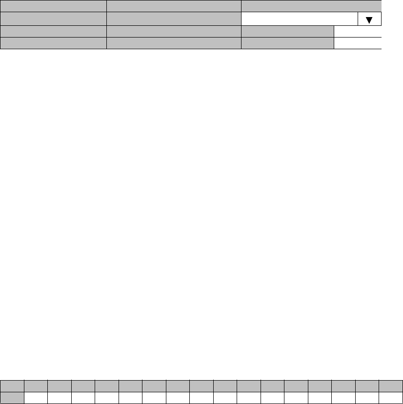
Others
27 Click on the “Others” sub-menu button in “Provisioning”.
EOW2 External Setting
28 Click on the either “Normal” or “Invert” control button.
Alarm Correlation Capability
29 Click on the either “On” or “Off” control button.
Note: Select “On” when really caused alarm is displayed.
Select “Off” when including derived alarm is displayed.
30 Click on the “Set” button in Common area to define the setting.
---EOW2 External Setting---
EOW2 External Setting Normal Invert
---Alarm Correlation Capability---
Alarm Correlation Capability Off On
ROI-S07047 METERING
-65-
8. METERING
1 Click on the “Metering” in “LCT Menu”.
2 Check the values indicated in metering text fields for each
metering item.
Notes: 1. No.1 and No.2 are indicated only for 1+1 configuration.
2. Both TX Power values of No.1 and No.2 are indicated in
Twinpath configuration only.
3. TX Power value * is indicated for standby TRP in Hot
Standby configuration.
4. Power Supply voltage of the TRP DC input varies
depending on IF cable length.
5. During total number of erroneous bits and total number
of correctly received bits are calculating, “Calculating”
is displayed.
LCT Menu
Alarm/Status
Equipment Setup
Inventory
AUX I/O
Maintenance
Provisioning
Metering
PMON (History)
----Metering---
No.1 No.2
TX Power [dBm] +0.7 *
RX Level [dBm] –65.2 –70.0
Power Supply [V] –45 –45
BER *.*E-10 Calculating
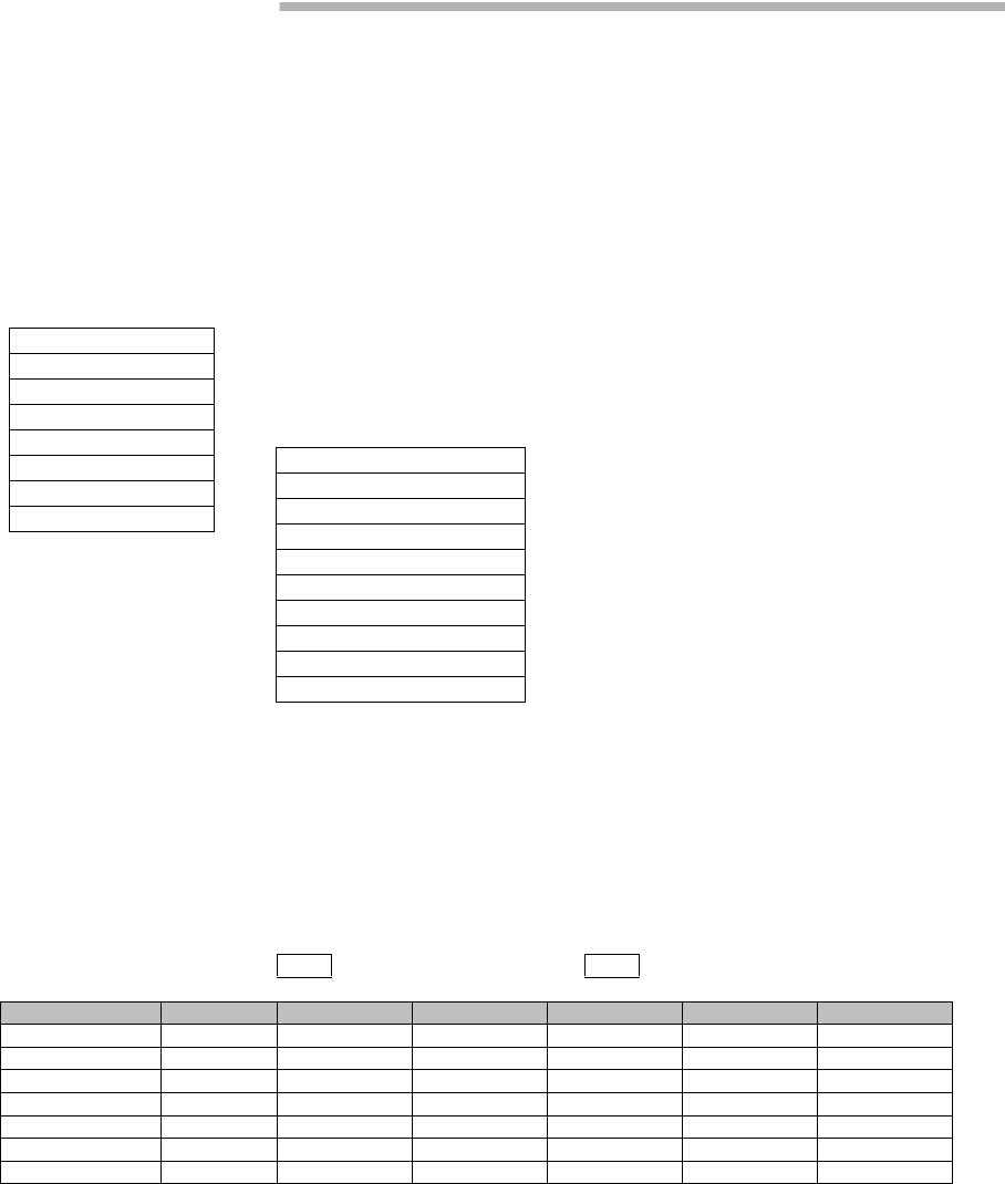
PMON ROI-S07047
-66-
9. PMON
9.1 PMON
9.1.1 PMON (History)
1 Click on the “PMON (History)” in “LCT Menu”.
2 Click on the “Reload” button in Common area.
RX Level (24h/15min)
3 Click on the “RX Level (24h/15min)” sub-menu button in
“PMON (History)”.
LCT Menu
Alarm/Status
Equipment Setup
Inventory
AUX I/O
Maintenance
Provisioning
Metering
PMON (History)
RX Level (24h/15min)
RX Level (7days/day)
Total (24h/15min)
Total (7days/day)
CSU (24h/15min)
CSU (7days/day)
RMON (Line)(24h/15min)
RMON (Line)(7days/day)
RMON (DMR)(24h/15min)
RMON (DMR)(7days/day)
---RX Level (15min)--- Maintenance Mode: On : Current Time
Date Time Status MIN (No.1) MAX (No.1) MIN (No.2) MAX (No.2)
2006/01/05 15:30-15:45 –59.7 –58.6 –59.3 –58.1
2006/01/05 15:45-16:00 –59.8 –58.7 –58.7 –58.2
2006/01/05 16:00-16:15 –59.5 –59.0 –58.7 –58.2
2006/01/05 16:15-16:30 –59.5 –59.0 –58.7 –58.2
2006/01/05 16:30-16:45 –59.5 –59.0 –71.2 –58.2
2006/01/05 16:45-17:00 –74.2 –55.8 –58.8 –54.1
2006/01/05 17:00-17:15 –59.5 –57.9 –58.8 –58.1
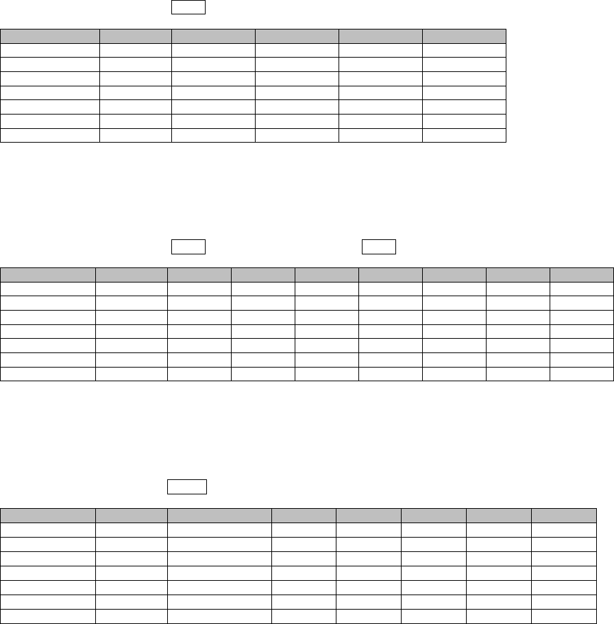
ROI-S07047 PMON
-67-
RX Level (7days/day)
4 Click on the “RX Level (7days/day)” sub-menu button in
“PMON (History)”.
Total (24h/15min)
5 Click on the “Total (24h/15min)” sub-menu button in “PMON
(History)”.
Total (7days/day)
6 Click on the “Total (7days/day)” sub-menu button in “PMON
(History)”.
---RX Level (day)--- Maintenance Mode: On
Date Status MIN(No.1) MAX(No.1) MIN(No.2) MAX(No.2)
2006/01/01 –59.7 –58.6 –59.3 –58.1
2006/01/02 –59.8 –58.7 –58.7 –58.2
2006/01/03 –59.5 –59.0 –58.7 –58.2
2006/01/04 –59.5 –59.0 –58.7 –58.2
2006/01/05 –59.5 –59.0 –71.2 –58.2
2006/01/06 –74.2 –55.8 –58.8 –54.1
2006/01/07 –59.5 –57.9 –58.8 –58.1
---Total (15min)---- Maintenance Mode: On : Current Time
Date Time Status OFS SEP BBE ES SES UAS
2006/01/05 15:30-15:45 000000
2006/01/05 15:45-16:00 000000
2006/01/05 16:00-16:15 000000
2006/01/05 16:15-16:30 000000
2006/01/05 16:30-16:45 000000
2006/01/05 16:45-17:00 000000
2006/01/05 17:00-17:15 000000
---Total (1day)--- Maintenance Mode: On
Date Status OFS SEP BBE ES SES UAS
2006/01/01 0 00000
2006/01/02 0 00000
2006/01/03 0 00000
2006/01/04 0 00000
2006/01/05 0 00000
2006/01/06 0 00000
2006/01/07 0 00000
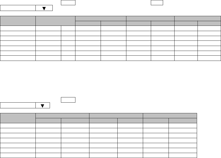
PMON ROI-S07047
-68-
CSU (24h/15min)
7 Click on the “CSU (24h/15min)” sub-menu button in “PMON
(History)”.
CSU (7day/1day)
8 Click on the “CSU (7day/day)” sub-menu button in “PMON
(History)”.
--- CSU (15min) --- :Maintenance Mode On :Current Time
CH01
Date Time Incoming CV-L Incoming CV-P Outgoing CV-P
Status Count Status Count Status Count
2009/03/01 09:30-09:45 0 0 0
2009/03/01 09:45-10:00 0 0 0
2009/03/01 10:00-10:15 0 0 0
2009/03/01 10:15-10:30 0 0 0
2009/03/01 10:30-10:45 0 0 0
2009/03/01 10:45-11:00 0 0 0
2009/03/01 11:00-11:15 0 0 0
--- CSU (1day) --- :Maintenance Mode On
CH01
Date Incoming CV-L Incoming CV-P Outgoing CV-P
Status Count Status Count Status Count
2009/03/01 0 0 0
2009/03/02 0 0 0
2009/03/03 0 0 0
2009/03/04 0 0 0
2009/03/05 0 0 0
2009/03/06 0 0 0
2009/03/07 0 0 0
ROI-S07047 PMON
-69-
9.1.2 RMON (History)
RMON (Line) (15min)
9 Click on the “RMON (Line) (24h/15min)” sub-menu button in
“PMON (History)”.
--- RMON (Line) (15min) --- :Maintenance Mode On :Current Time
Port1
Date Time Status 1 2 3 4
2009/03/01 00:00-00:15 1: RX Unicast PKTS
2009/03/01 00:15-00:30 2: RX Broadcast PKTS
2009/03/01 00:30-00:45 3: RX Multicast PKTS
2009/03/01 00:45-01:00 4: RX Pause PKTS
2009/03/01 01:00-01:15 5: RX CRC Errors
2009/03/01 01:15-01:30 6: RX Align Errors
2009/03/01 01:30-01:45 7: RX Symbol Errors
2009/03/01 01:45-02:00 8: RX Undersize PKTS
2009/03/01 02:00-02:15 9: RX Fragments
2009/03/01 02:15-02:30 10: RX PKTS 64
2009/03/01 02:30-02:45 11: RX PKTS 65-127
2009/03/01 02:45-03:00 12: RX PKTS 128-255
2009/03/01 03:00-03:15 13: RX PKTS 256-511
2009/03/01 03:15-03:30 14: RX PKTS 512-1023
2009/03/01 03:30-03:45 15: RX PKTS 1024-1536
2009/03/01 04:45-05:00 16: RX PKTS 1537-MAX
2009/03/01 05:00-05:15 17: RX Jabbers
2009/03/01 05:15-05:30 18: TX Unicast PKTS
2009/03/01 05:30-05:45 19: TX Broadcast PKTS
2009/03/01 05:45-06:00 20: TX Multicast PKTS
2009/03/01 06:00-06:15 21: TX Pause PKTS
2009/03/01 06:15-06:30 22: TX Total Collisions
2009/03/01 06:30-06:45
2009/03/01 06:45-07:00

PMON ROI-S07047
-70-
RMON (Line) (1day)
10 Click on the “RMON (Line) (7days/day)” sub-menu button in
“PMON (History)”.
--- RMON (Line) (1day) --- :Maintenance Mode On
Port1
Date Status 12345
2009/03/01 1: RX Unicast PKTS
2009/03/02 2: RX Broadcast PKTS
2009/03/03 3: RX Multicast PKTS
2009/03/04 4: RX Pause PKTS
2009/03/05 5: RX CRC Errors
2009/03/06 6: RX Align Errors
2009/03/07 7: RX Symbol Errors
8: RX Undersize PKTS
9: RX Fragments
10: RX PKTS 64
11: RX PKTS 65-127
12: RX PKTS 128-255
13: RX PKTS 256-511
14: RX PKTS 512-1023
15: RX PKTS 1024-1536
16: RX PKTS 1537-MAX
17: RX Jabbers
18: TX Unicast PKTS
19: TX Broadcast PKTS
20: TX Multicast PKTS
21: TX Pause PKTS
22: TX Total Collisions
ROI-S07047 PMON
-71-
RMON (DMR) (15min)
11 Click on the “RMON (DMR) (24h/15min)” sub-menu button in
“PMON (History)”.
--- RMON (DMR) (15min) --- :Maintenance Mode On :Current Time
Port1
Date Time Status 1 2 3 4
2009/03/01 00:00-00:15 1: RX Unicast PKTS
2009/03/01 00:15-00:30 2: RX Broadcast PKTS
2009/03/01 00:30-00:45 3: RX Multicast PKTS
2009/03/01 00:45-01:00 4: RX Pause PKTS
2009/03/01 01:00-01:15 5: RX CRC Errors
2009/03/01 01:15-01:30 6: RX Fragments
2009/03/01 01:30-01:45 7: RX PKTS 64
2009/03/01 01:45-02:00 8: RX PKTS 65-127
2009/03/01 02:00-02:15 9: RX PKTS 128-255
2009/03/01 02:15-02:30 10: RX PKTS 256-511
2009/03/01 02:30-02:45 11: RX PKTS 512-1023
2009/03/01 02:45-03:00 12: RX PKTS 1024-1536
2009/03/01 03:00-03:15 13: RX PKTS 1537-MAX
2009/03/01 03:15-03:30 14: RX Jabbers
2009/03/01 03:30-03:45 15: TX Unicast PKTS
2009/03/01 04:45-05:00 16: TX Broadcast PKTS
2009/03/01 05:00-05:15 17: TX Multicast PKTS
2009/03/01 05:15-05:30 18: TX Pause PKTS
2009/03/01 05:30-05:45
2009/03/01 05:45-06:00

PMON ROI-S07047
-72-
RMON (DMR) (1day)
12 Click on the “RMON (DMR) (7days/day)” sub-menu button in
“PMON (History)”.
--- RMON (DMR) (1day) --- :Maintenance Mode On
Port1
Date Status 1 2345
2009/03/01 1: RX Unicast PKTS
2009/03/02 2: RX Broadcast PKTS
2009/03/03 3: RX Multicast PKTS
2009/03/04 4: RX Pause PKTS
2009/03/05 5: RX CRC Errors
2009/03/06 6: RX Fragments
2009/03/07 7: RX PKTS 64
8: RX PKTS 65-127
9: RX PKTS 128-255
10: RX PKTS 256-511
11: RX PKTS 512-1023
12: RX PKTS 1024-1536
13: RX PKTS 1537-MAX
14: RX Jabbers
15: TX Unicast PKTS
16: TX Broadcast PKTS
17: TX Multicast PKTS
18: TX Pause PKTS
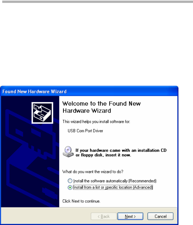
ROI-S07047 INSTALLATION OF USB
-73-
10. INSTALLATION OF USB
Following procedure explains how to install the USB modem driver to a
windows XP PC.
1 Connect the PC with a USB cable between the LCT port and the
USB port.
2 Select “Install from a list or specific location [Advanced]” and
Click on the “Next” button.
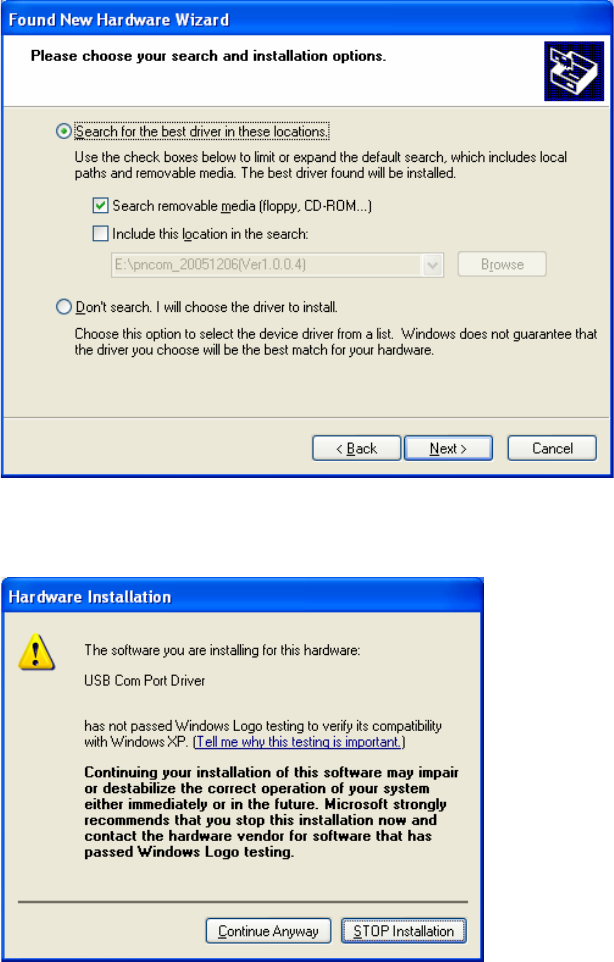
INSTALLATION OF USB ROI-S07047
-74-
3 Insert the CD-ROM of the USB driver to the PC and select
“Search for the best driver in these locations” and check
“Search removal media [floppy, CD-ROM...],” then, Click on
the “Next” button.
4 Click “Continue Anyway” button in the Hardware Installation
alert pop-up.

ROI-S07047 INSTALLATION OF USB
-75-
5 USB driver installation will be started.
6 Click “Finish” button in the “Found New Hardware Wizard”
after installation has been completed.
Note: There is a possibility that the USB connection is dropped during a
long-duration operation depending on the device type of
computer. In the case of a connection failure, please reconnect
the dial-up connection.
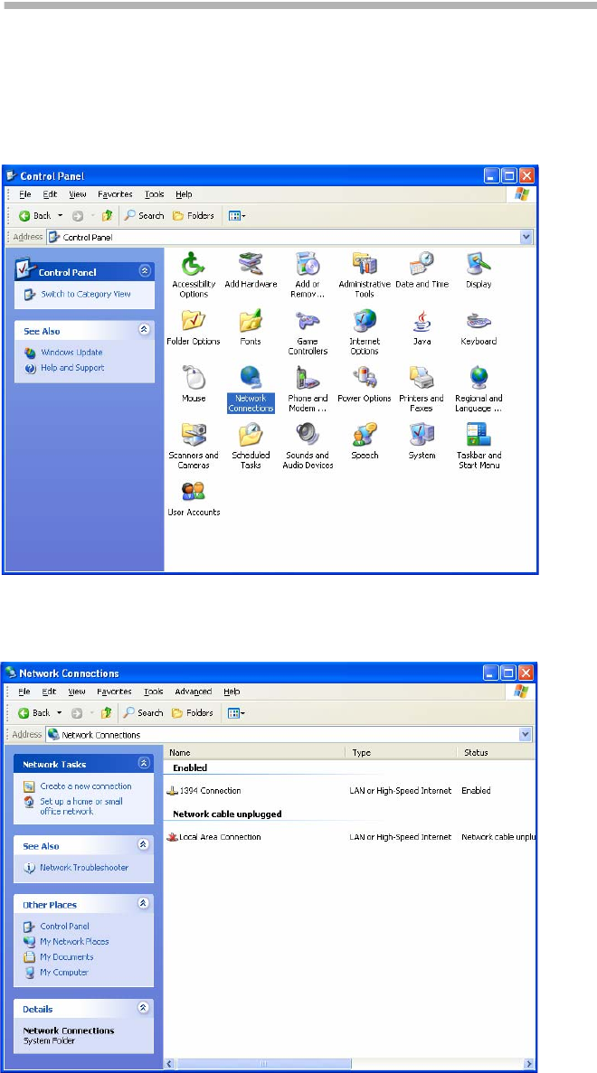
DIAL-UP SETTING ROI-S07047
-76-
11. DIAL-UP SETTING
Following procedure explains when the Dial-up is set to the PC on
Windows XP.
1 Click on “Start”→“Setting”→“Control Panel” and on
“Network Connections” icon to start the Dialup setting.
2The “Network Connections” window appears. Click on the
“Create a new connection” in the Network Tasks category.
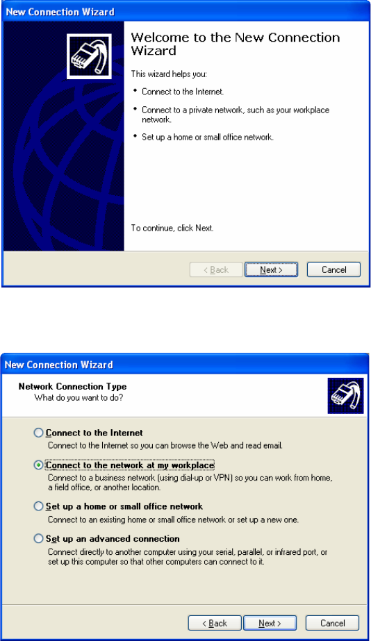
ROI-S07047 DIAL-UP SETTING
-77-
3The “Welcome to the New Connection Wizard” window
appears. Click on the “Next” button to continue.
4 Select “Connect to the network at my workplace” and Click
on the “Next” button to continue.
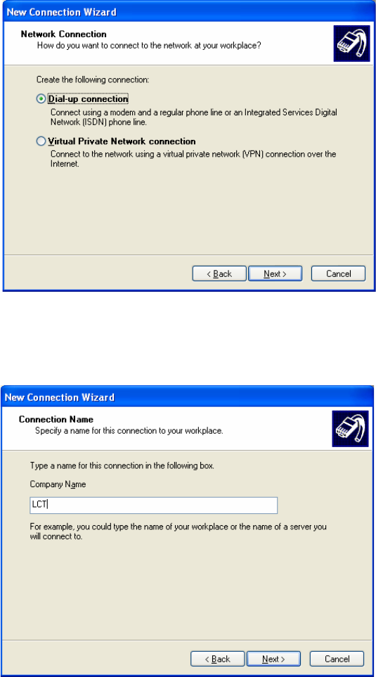
DIAL-UP SETTING ROI-S07047
-78-
5 Select option “Dial-up connection” and Click on the “Next”
button to continue.
6On the “New Connection Wizard” window, enter “LCT” in
the “Company Name” entry field and Click on the “Next”
button to continue.
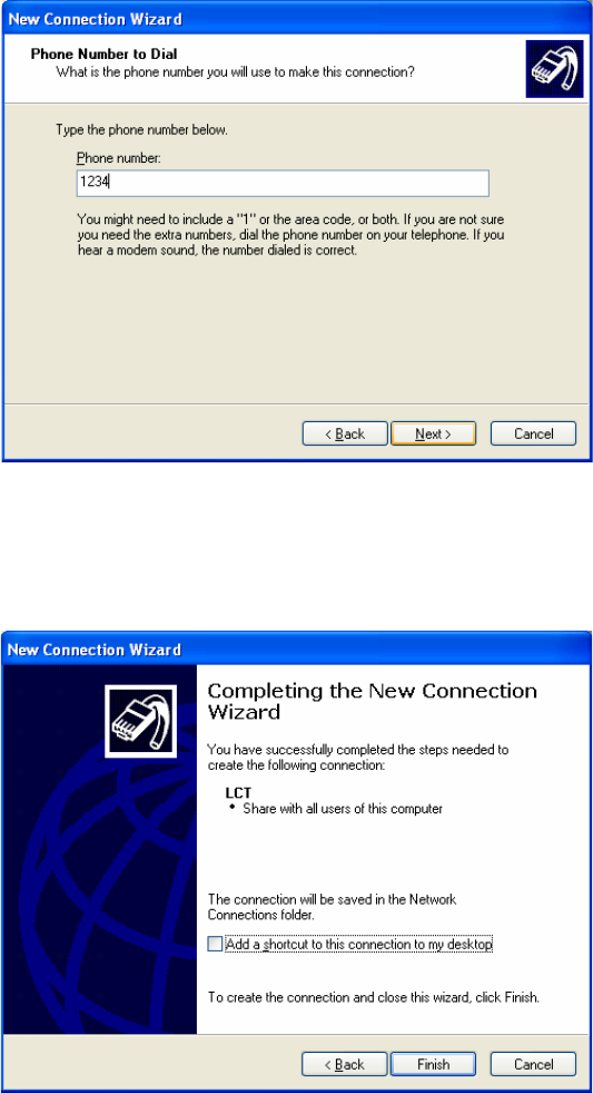
ROI-S07047 DIAL-UP SETTING
-79-
7 Enter phone number in the “Phone number” entry field and
Click on the “Next” button to continue.
8 Verify that the connection “LCT” has displayed as the
connection registered. You can also create a short-cut on your
desktop if you need. Click on the “Finish” button.
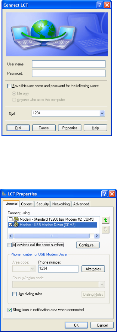
DIAL-UP SETTING ROI-S07047
-80-
9On “Connect LCT” dialog, click “Properties”.
10 Verify that “Modem-USB Modem Driver [COM(#)]” is
displayed on the General dialog box connect using check box,
and select “Show icon in notification area when connected” in
the LCT Properties dialog. Then, Click on the “Configure”
button.
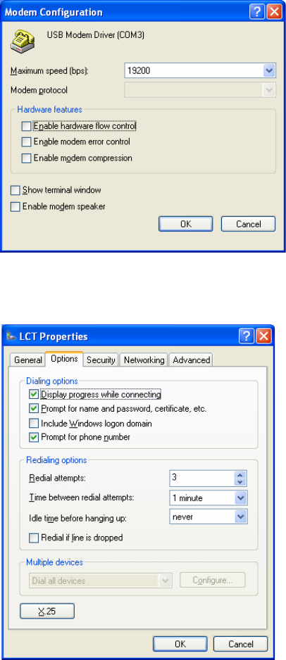
ROI-S07047 DIAL-UP SETTING
-81-
11 On “Modem Configuration” dialog, check that unchecked all
five boxes, then Click on the “OK” button.
12 Retain the default setting on the “Options” tab, click the
“Security” tab.
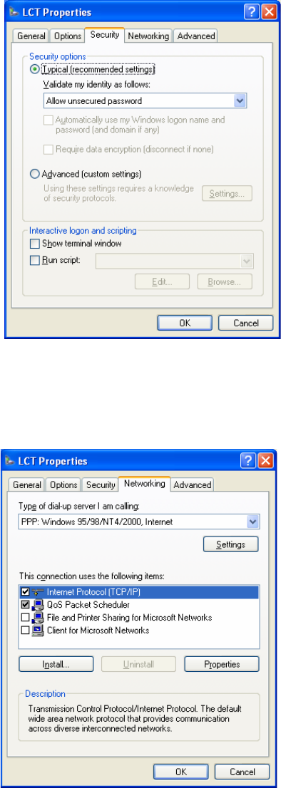
DIAL-UP SETTING ROI-S07047
-82-
13 Retain the default setting on the “Security” tab, click the
“Networking” tab.
14 On the Networking tab, verify that PPP... is displayed in the
“Type of dial-up server I am calling” setting field, unchecked
“File and Printer... and Client for Microsoft....”, “Client for
Microsoft Networks”.
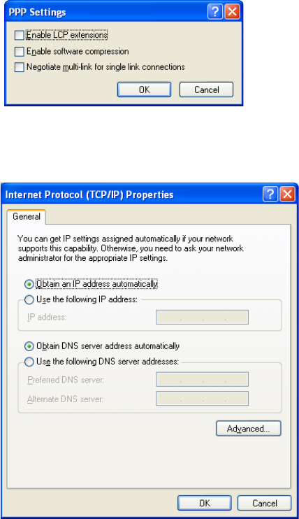
ROI-S07047 DIAL-UP SETTING
-83-
15 Click “Settings” button, unchecked all the boxes in the “PPP
Settings” dialog as shown below. Click “OK” to go back to the
previous window. Point “Internet Protocol (TCP/IP)” and then
click “Properties”.
16 Verify that both “Obtain an IP address automatically” and
“Obtain DNS server address automatically” are selected.
17 Click on the “Advanced” button,
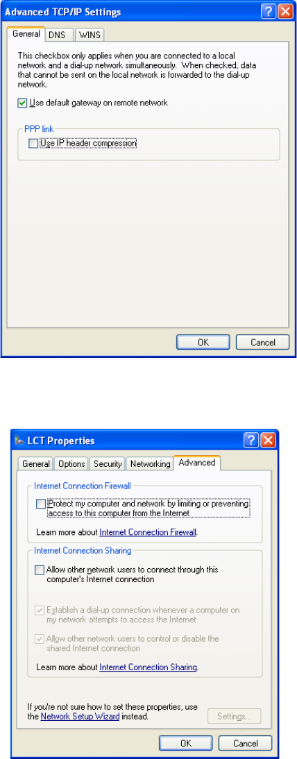
DIAL-UP SETTING ROI-S07047
-84-
18 In the “Advanced TCP/IP Settings” dialog, mark check box of
“Use default gateway on remote network” and for the PPP
link is unchecked, then Click “OK”.
19 Retain the default setting on the “Advanced” tab and click
“OK”.
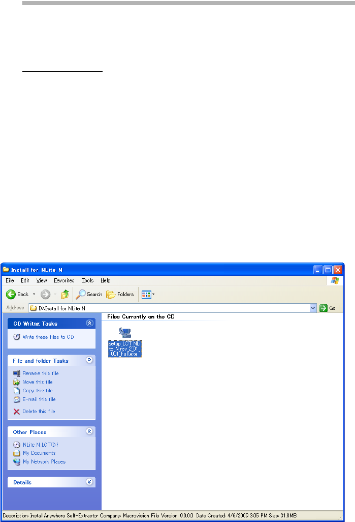
ROI-S07047 LCT INSTALLATION
-85-
12.
LCT INSTALLATION
The LCT for NLite N is found in the CD-ROM which is attached to the
MDP equipment.
LCT Installation
Close LCT Application and other applications that may be running on the
PC. (It can be installed wrong when other applications are working on the
PC.)
When the LCT Application has been installed, uninstall it and perform the
re-installation.
1 Insert the CD-ROM to the CD-ROM player of the PC used for
LCT.
2 Double click on the “
setup_LCT_NLite_N_rev_2_xx_xxx_Full.exe
”
icon, then the installer is started up and the installation of the LCT into
the PC is executed.
(When “setup_LCT_NLite_N_rev_2_01_001_Full.exe”.)
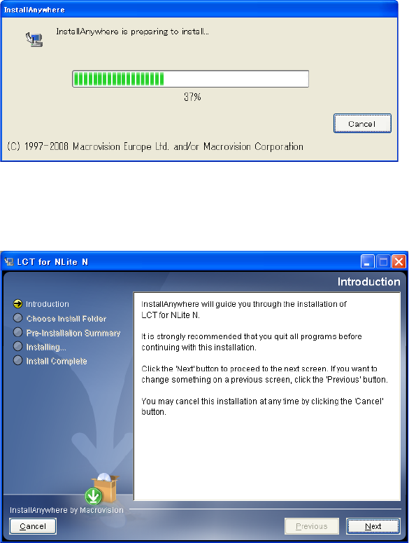
LCT INSTALLATION ROI-S07047
-86-
3 The installer progress screen appears, wait for a while.
4“Introduction” appears.
5Read “Introduction” and click on the “Next” button to
continue.
6“Choose Installer Folder” appears.
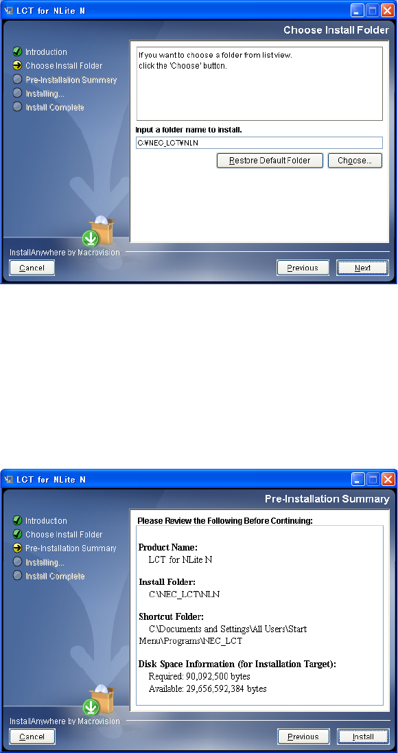
ROI-S07047 LCT INSTALLATION
-87-
7 Click on the “Next” button when default directory
(recommended) is used or enter the folder name for installing
directory.
Note: When the folder name is creating, do not enter space
between letters of the directory name.
8 When the folder name has been decided, click on the “Next”
button to continue.
9 Make sure that the installing folder name and empty capacity of
the hard disk are properly decided, then, click on the “Next”
button to continue.
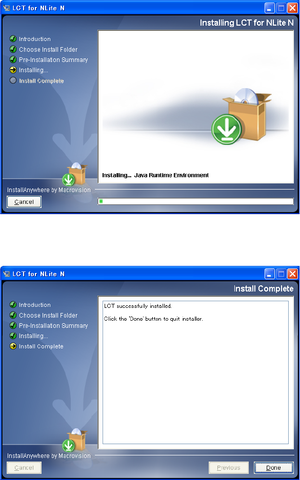
LCT INSTALLATION ROI-S07047
-88-
10 Wait for a while until installation finishes.
11 When the installation has been completed, click on the “Done”
button.
12 “Information” dialog appears.
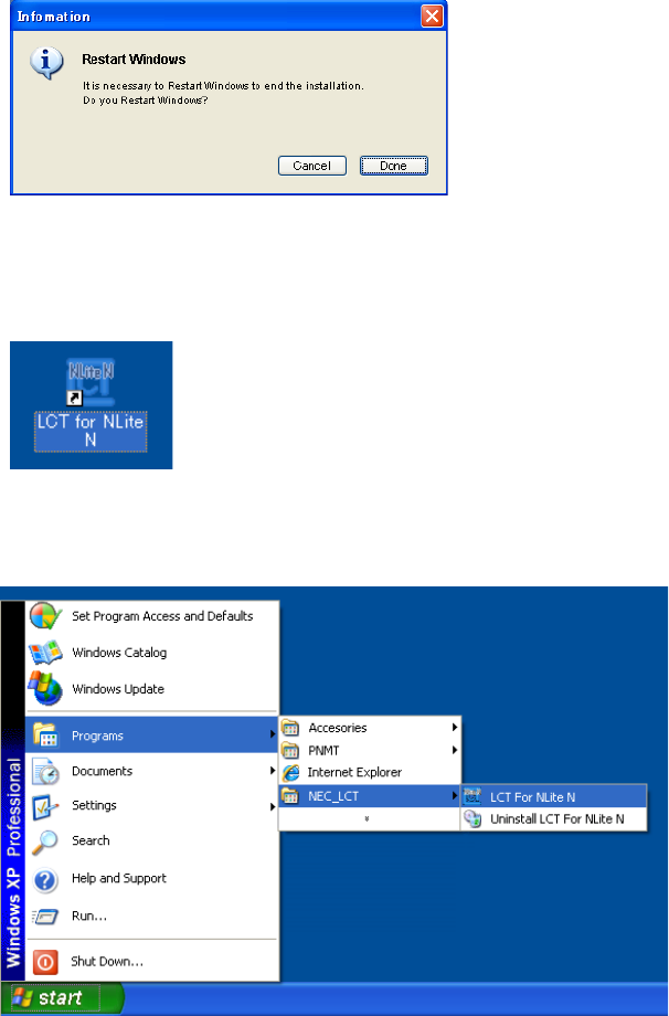
ROI-S07047 LCT INSTALLATION
-89-
13 Click on the “Done” button to restart the PC.
14 Then, following short-cut icon is made on the restarted desktop.
15 Click on the short-cut icon or select the “Programs” →
“NEC_LCT” → “LCT For NLite N” from the “start” menu.
16 The LCT is started up and “Login” dialog appears.
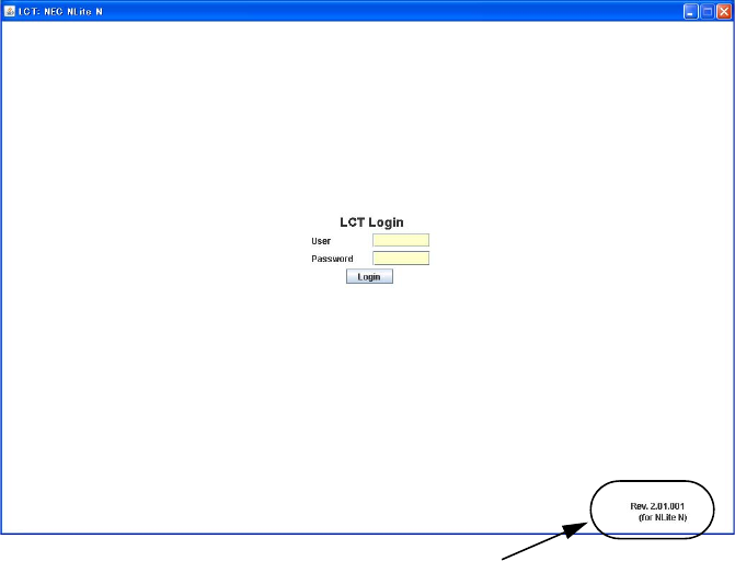
LCT INSTALLATION ROI-S07047
-90-
17 Confirm that the LCT Version is “
Rev. 2.xx.xxx
(for NLite N)
”.
18 Perform Dial-up access and login to the MDP.
Rev. 2.xx.xxx (for NLite N)
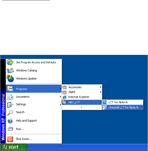
ROI-S07047 LCT INSTALLATION
-91-
LCT Uninstallation
Close LCT Application and other applications that may be running on the
PC. (It can be uninstalled wrong when other applications are working on
the PC.)
1 Select the “Programs” → “NEC_LCT” → “Uninstall LCT
For NLite N” from the “start” menu for uninstalling LCT.
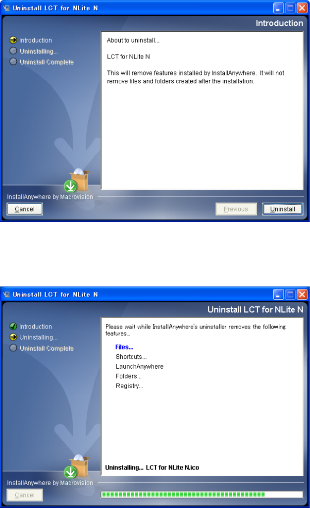
LCT INSTALLATION ROI-S07047
-92-
2Read “Introduction” and click on the “Uninstall” button, then,
the uninstalling program is started up.
3 Wait for a while until uninstallation finishes.
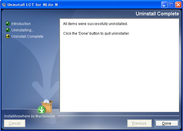
ROI-S07047 LCT INSTALLATION
-93-
4 When the program has been uninstalled, click on the “Done”
button.
5 Uninstallation finishes.
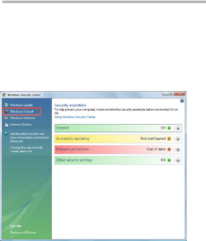
FIREWALL SETUP FOR WINDOWS VISTA ROI-S07047
-94-
13. FIREWALL SETUP FOR
WINDOWS VISTA
For operating LCT for NLite N with Windows Vista, setup the windows
firewall by the following procedure.
13.1 Firewall Setup
1 Go to Control Panel. => Windows Security Center.
2 Click Windows Firewall.
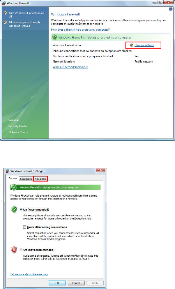
ROI-S07047 FIREWALL SETUP FOR WINDOWS VISTA
-95-
3 Select Change Settings.
4 Select Advanced tab.
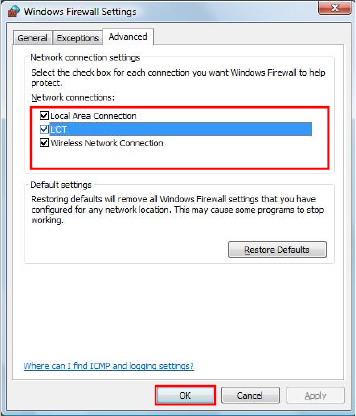
FIREWALL SETUP FOR WINDOWS VISTA ROI-S07047
-96-
5 Remove check mark on connection name.
NOTE: Configuring the firewall as above, a security warning icon will
appear on the task tray. After terminating LCT, please check
mark on connection name. You will need to re-configure the
firewall each time you startup LCT.
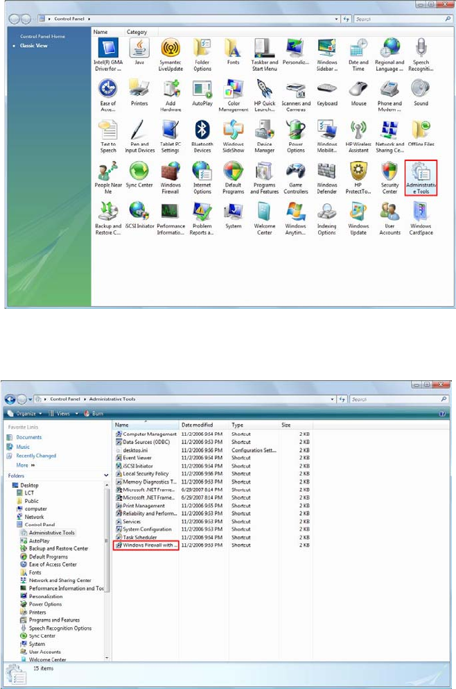
ROI-S07047 FIREWALL SETUP FOR WINDOWS VISTA
-97-
13.2 Firewall Setup (with Advanced Security)
This procedure enables Run LCT with Firewall.
1 Click Start => Control Panel and the Administrative Tools
icon to start configuring Firewall.
2 Click Windows Firewall with Advanced Security.
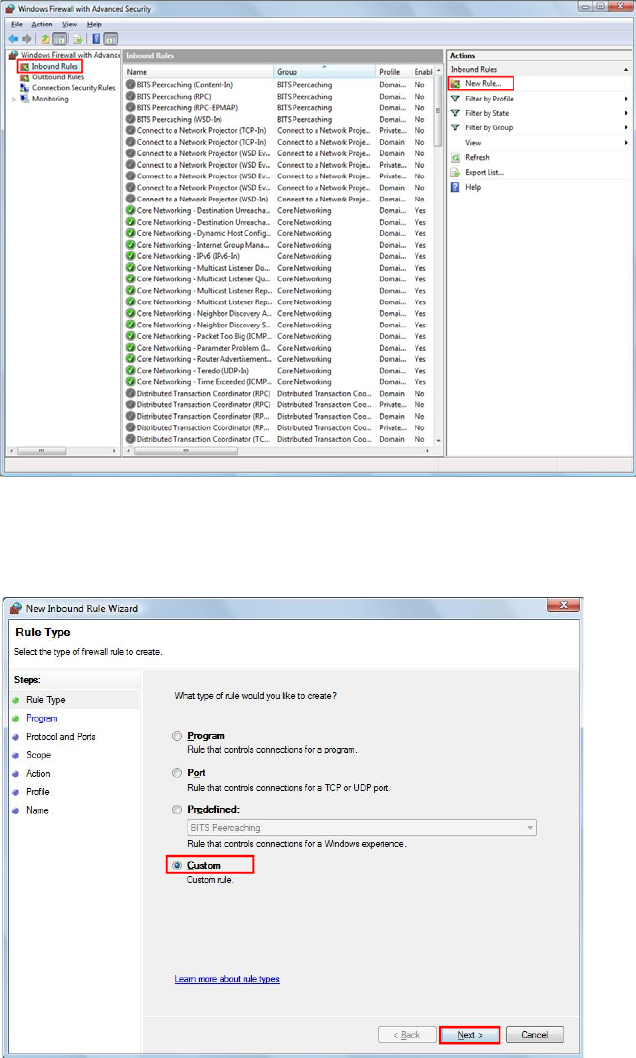
FIREWALL SETUP FOR WINDOWS VISTA ROI-S07047
-98-
3 In the Windows Firewall with Advanced Security. Window
appears Click Inbound Rules and New Rules... on Actions.
4 In the Window appears select Custom. And click Next.
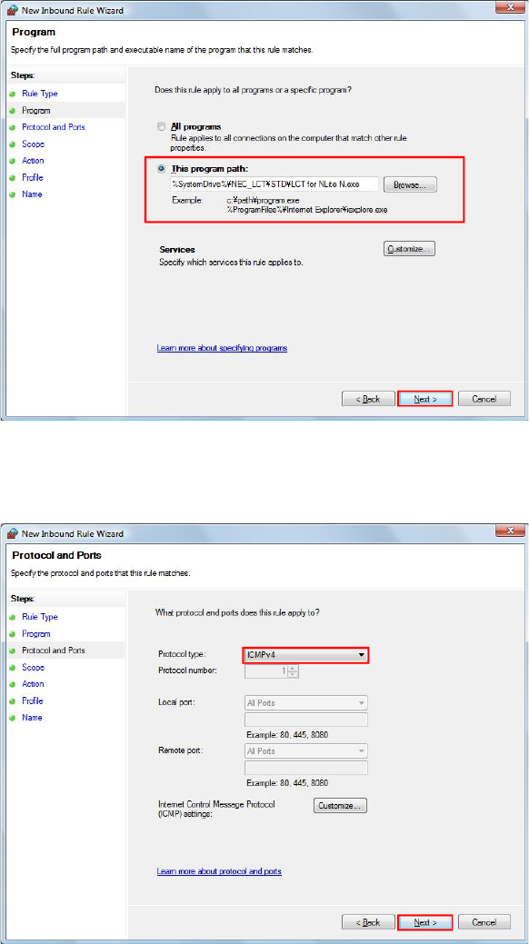
ROI-S07047 FIREWALL SETUP FOR WINDOWS VISTA
-99-
5 Select This program path and Click Browse. Select the LCT on
“LCT Install PATH\LCT for NLite N.exe” Click Next.
6 Select Protocol type ICMPv4 and Click Next.
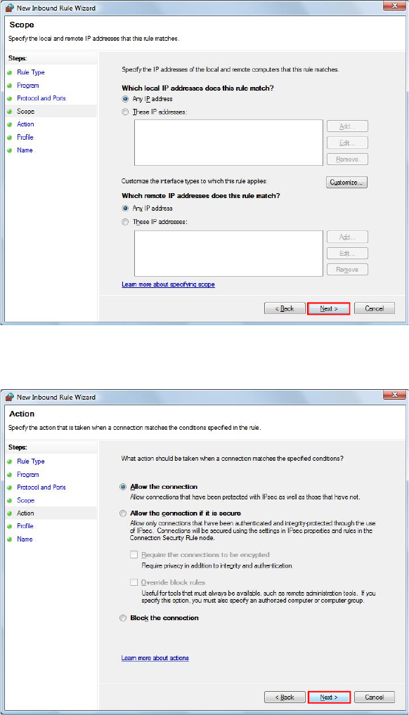
FIREWALL SETUP FOR WINDOWS VISTA ROI-S07047
-100-
7 Retain the default setting Click Next
8 Retain the default setting Click Next.
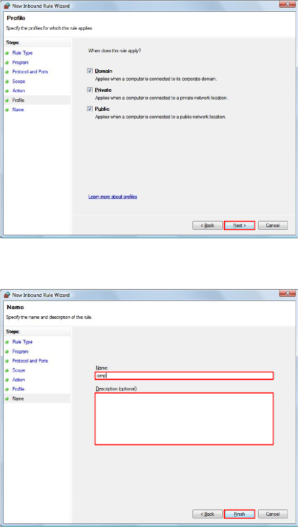
ROI-S07047 FIREWALL SETUP FOR WINDOWS VISTA
-101-
9 Retain the default setting. Click Next.
10 Input Name filed and Description field and Click Finish.
FIREWALL SETUP FOR WINDOWS VISTA ROI-S07047
-102-
102 pages
(This page is intentionally left blank.)