NexusData TR0001 Network Transceiver Repeater User Manual 274991

NexusData Ltd. Network Transceiver Repeater 274991

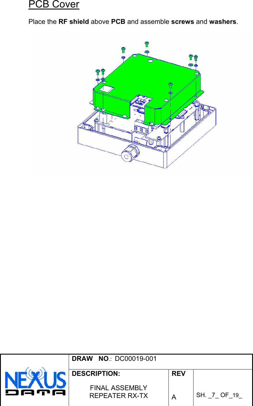
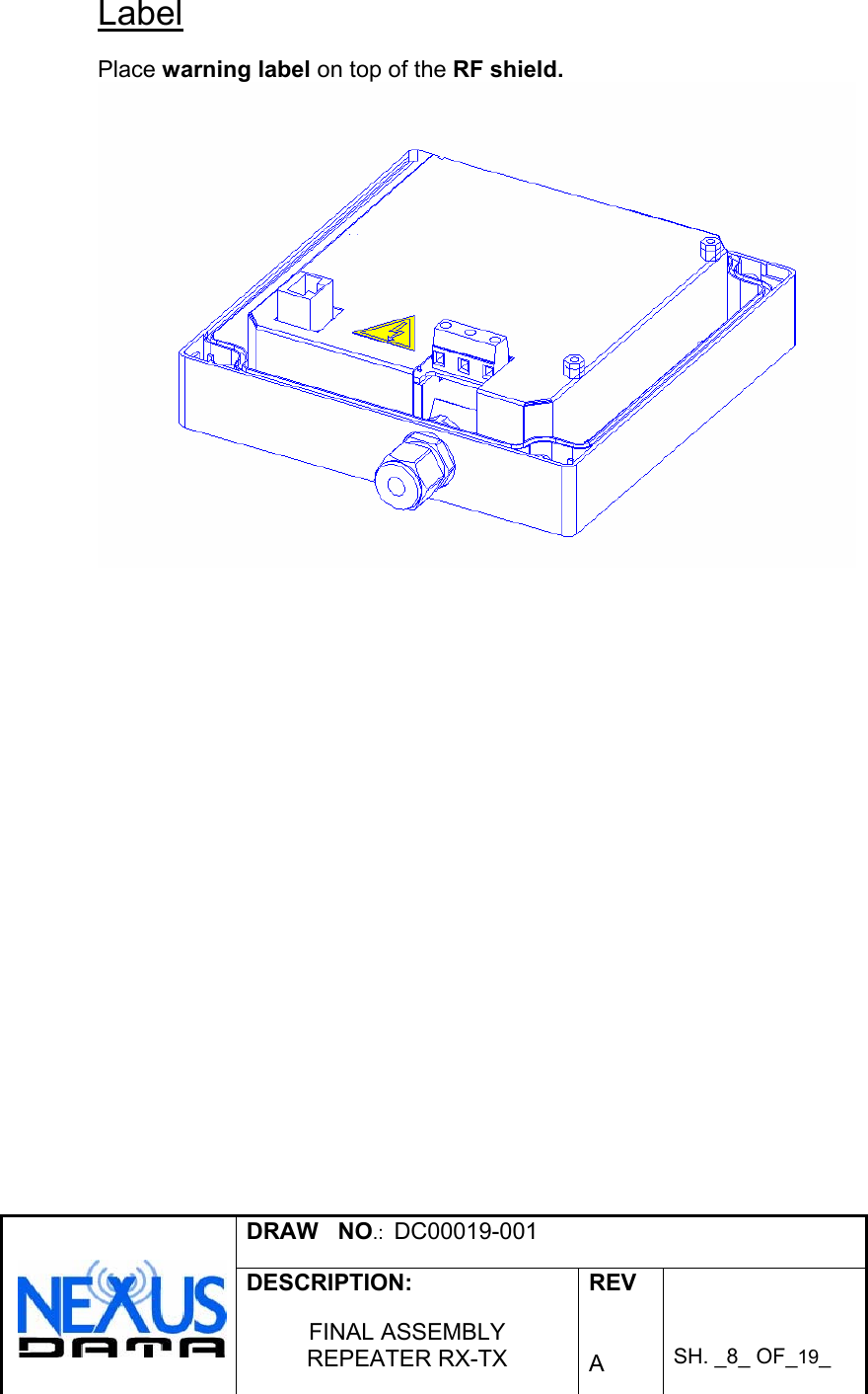
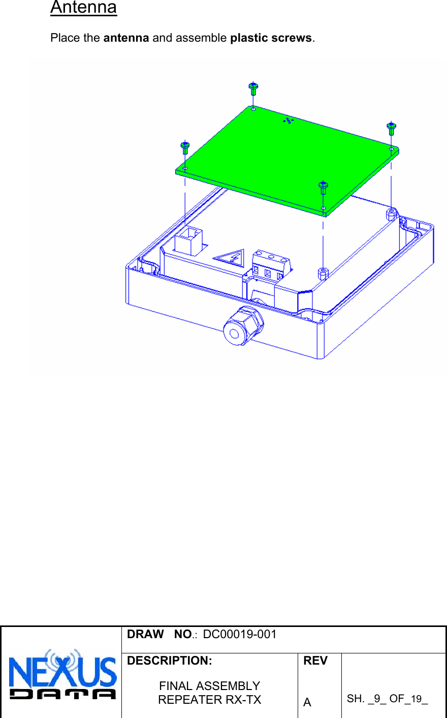
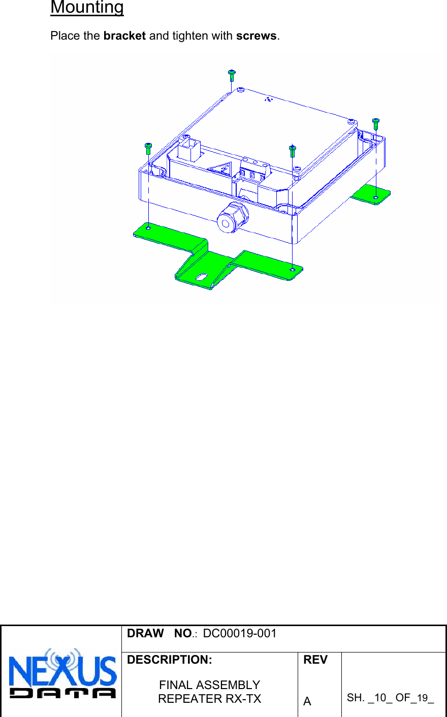
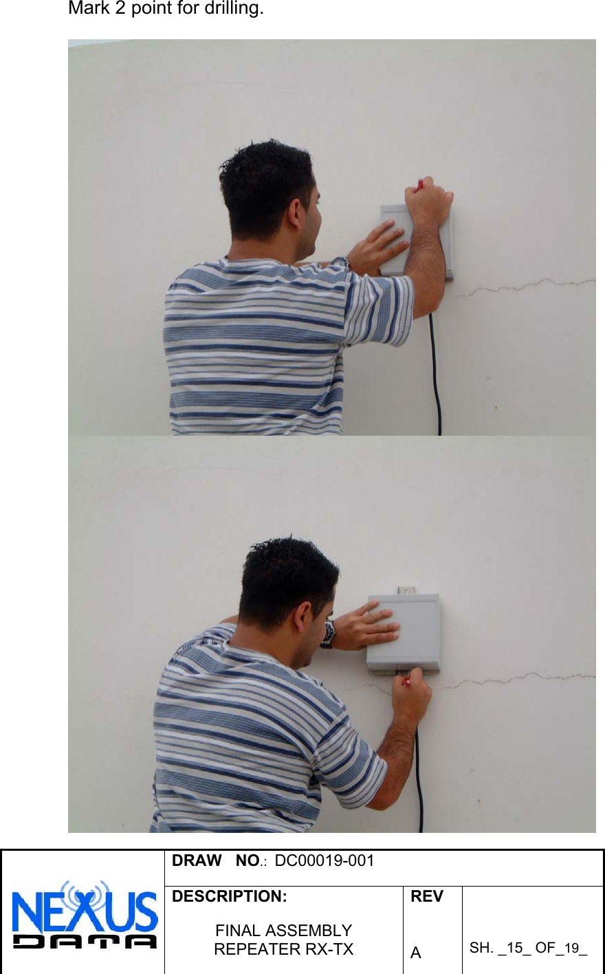
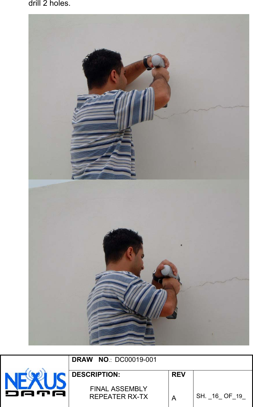
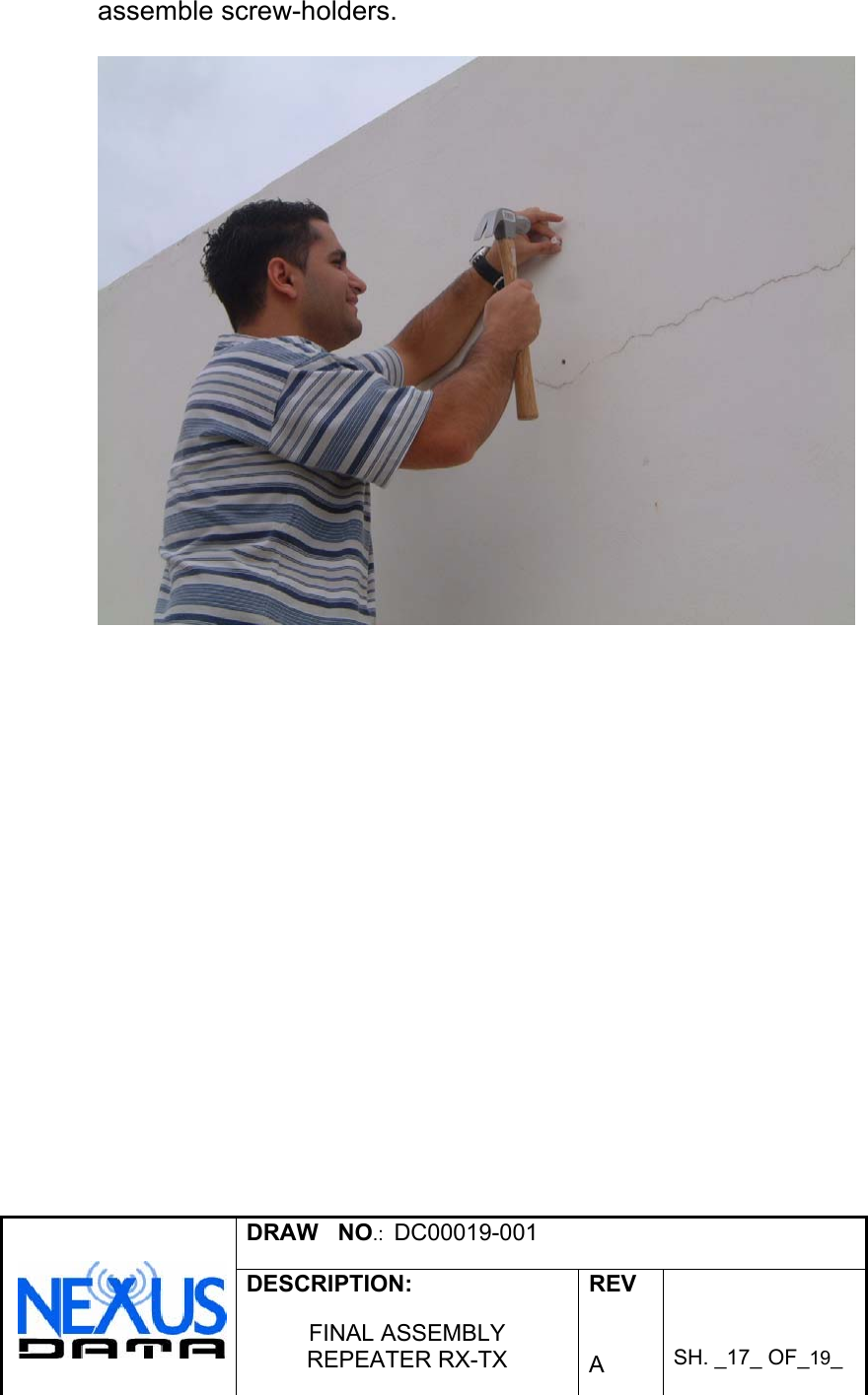
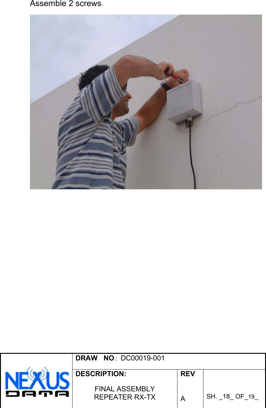
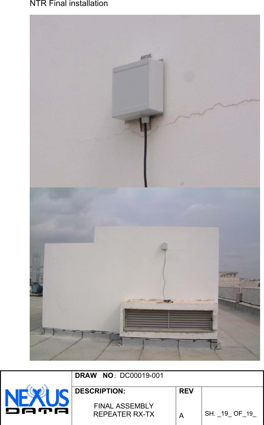
Revised Corrected User Installation Manual

REV.      ECO No.  APPROVED  NAME  SIGNATURE A First release                                                                                                                                                                                                                                                               NAME SIGNATURE DATE  DESCRIPTION:  Product  Manager       R&D Manager      INSTALLATION GUIDE Testing      NTR   Manufacturing Eng.  Shay Versano      QA      Engineering  Shay Versano       SH  1 OF    DRAW No.    DC00019-001 REV. A
 DRAW   NO.:  DC00019-001   DESCRIPTION:  FINAL ASSEMBLY REPEATER RX-TX  REV   A    SH. _2_ OF_19_   Table of Contents  FCC Warning ................................................................................................................... 3 Mechanical Assembly..................................................................................................... 4 Front Box ....................................................................................................................... 4 Gland ............................................................................................................................. 5 PCB Assembly............................................................................................................... 6 PCB Cover..................................................................................................................... 7 Label.............................................................................................................................. 8 Antenna ......................................................................................................................... 9 Mounting...................................................................................................................... 10 AC Cable ..................................................................................................................... 11 Top Cover.................................................................................................................... 12 Final Assembly ............................................................................................................ 13 Field Installation............................................................................................................ 14 General Instructions .................................................................................................... 14 Installation Steps ......................................................................................................... 14
 DRAW   NO.:  DC00019-001   DESCRIPTION:  FINAL ASSEMBLY REPEATER RX-TX  REV   A    SH. _3_ OF_19_     FCC Warning   FCC Warning Modifications not expressly approved by the manufacturer could void the user authority to operate the equipment under FCC Rules.
 DRAW   NO.:  DC00019-001   DESCRIPTION:  FINAL ASSEMBLY REPEATER RX-TX  REV   A    SH. _4_ OF_19_   Mechanical Assembly  Front Box  Attach standoffs with plain washer, nut and spring washer to the lower board.     Attach the lower board into the front box and assemble screws.
 DRAW   NO.:  DC00019-001   DESCRIPTION:  FINAL ASSEMBLY REPEATER RX-TX  REV   A    SH. _5_ OF_19_   Gland  Assemble gland with nut and washer.
 DRAW   NO.:  DC00019-001   DESCRIPTION:  FINAL ASSEMBLY REPEATER RX-TX  REV   A    SH. _6_ OF_19_   PCB Assembly  Assemble the PCB into the front box and hold it with standoffs, screws, and washers.
 DRAW   NO.:  DC00019-001   DESCRIPTION:  FINAL ASSEMBLY REPEATER RX-TX  REV   A    SH. _7_ OF_19_   PCB Cover  Place the RF shield above PCB and assemble screws and washers.
 DRAW   NO.:  DC00019-001   DESCRIPTION:  FINAL ASSEMBLY REPEATER RX-TX  REV   A    SH. _8_ OF_19_   Label  Place warning label on top of the RF shield.
 DRAW   NO.:  DC00019-001   DESCRIPTION:  FINAL ASSEMBLY REPEATER RX-TX  REV   A    SH. _9_ OF_19_   Antenna  Place the antenna and assemble plastic screws.
 DRAW   NO.:  DC00019-001   DESCRIPTION:  FINAL ASSEMBLY REPEATER RX-TX  REV   A    SH. _10_ OF_19_   Mounting  Place the bracket and tighten with screws.
 DRAW   NO.:  DC00019-001   DESCRIPTION:  FINAL ASSEMBLY REPEATER RX-TX  REV   A    SH. _11_ OF_19_   AC Cable  place the AC cable into the front box        Assemble AC cable with screws
 DRAW   NO.:  DC00019-001   DESCRIPTION:  FINAL ASSEMBLY REPEATER RX-TX  REV   A    SH. _12_ OF_19_    Top Cover  Place the top cover on the front box and assemble screws.    Sealed the top cover with strips.
 DRAW   NO.:  DC00019-001   DESCRIPTION:  FINAL ASSEMBLY REPEATER RX-TX  REV   A    SH. _13_ OF_19_   Final Assembly
 DRAW   NO.:  DC00019-001   DESCRIPTION:  FINAL ASSEMBLY REPEATER RX-TX  REV   A    SH. _14_ OF_19_   Field Installation  General Instructions  The NTR must be installed at least 3 meters above the floor. Select the installation location in where no moving/mobile nor static objects would exist or enter into within 2 meters of the NTR surrounding, excluding the wall or pipe where the NTR is installed on.     Installation Steps  Locate installation place, on a roof of a dominate building in the area where the NTR services are required.
 DRAW   NO.:  DC00019-001   DESCRIPTION:  FINAL ASSEMBLY REPEATER RX-TX  REV   A    SH. _15_ OF_19_   Mark 2 point for drilling.
 DRAW   NO.:  DC00019-001   DESCRIPTION:  FINAL ASSEMBLY REPEATER RX-TX  REV   A    SH. _16_ OF_19_   drill 2 holes.
 DRAW   NO.:  DC00019-001   DESCRIPTION:  FINAL ASSEMBLY REPEATER RX-TX  REV   A    SH. _17_ OF_19_   assemble screw-holders.
 DRAW   NO.:  DC00019-001   DESCRIPTION:  FINAL ASSEMBLY REPEATER RX-TX  REV   A    SH. _18_ OF_19_      Assemble 2 screws.
 DRAW   NO.:  DC00019-001   DESCRIPTION:  FINAL ASSEMBLY REPEATER RX-TX  REV   A    SH. _19_ OF_19_   NTR Final installation

Navigation menu