Nokia Solutions and Networks CPE25300 Non-line of Sight Wireless Data Link User Manual 285a66
Nokia Solutions and Networks Non-line of Sight Wireless Data Link 285a66
UserManual.wiki
>
Nokia Solutions and Networks
>
CPE25300 User Manual
>
Manual
Contents
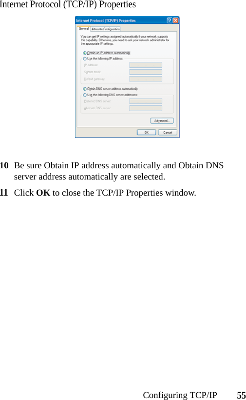
1.
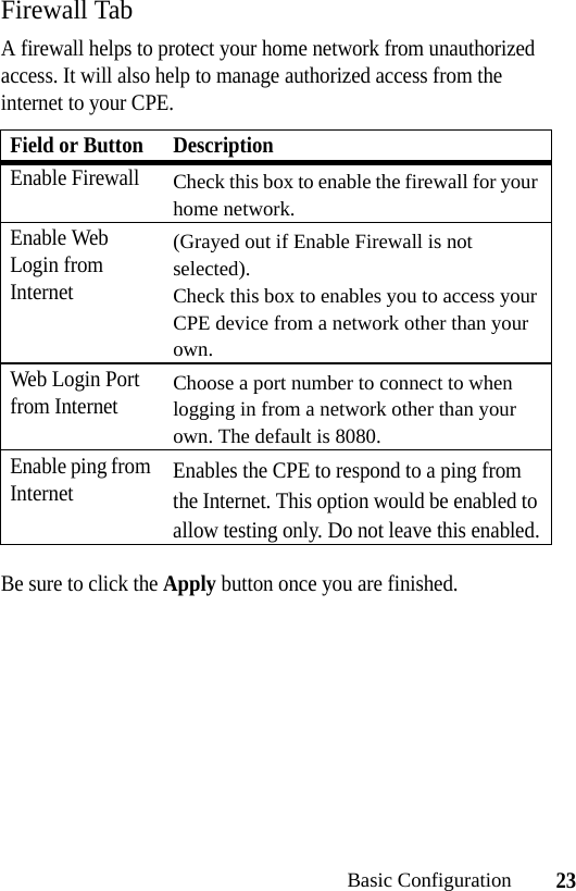
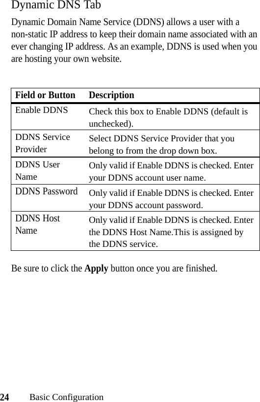
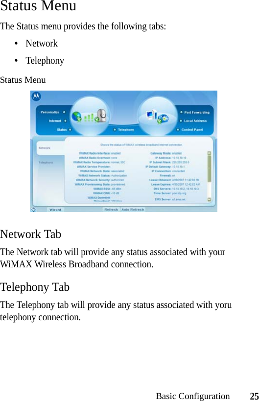
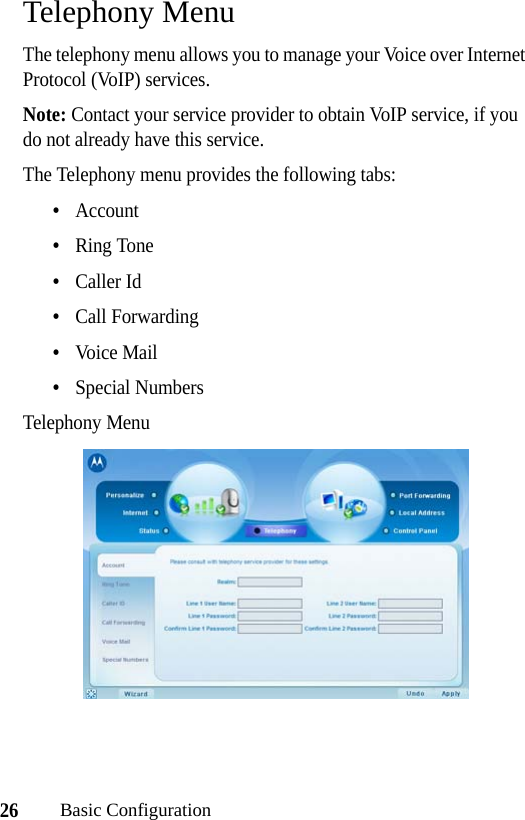
Manual
2.
Manual 2
3.
Manual 3
Manual
Navigation menu
Upload a User Manual
Namespaces
Wiki Guide
HTML
PDF
Info
Views
User Manual
Discussion / Help
Navigation