Nokia Solutions and Networks T7HN1 2.5 GHz Diversity Access Point User Manual users manual 4
Nokia Solutions and Networks 2.5 GHz Diversity Access Point users manual 4
Contents
- 1. users manual 1
- 2. users manual 2
- 3. users manual 3
- 4. users manual 4
- 5. users manual 5
users manual 4
Base Control Unit Installation Chapter 4: Access P oint Hardw are Installation
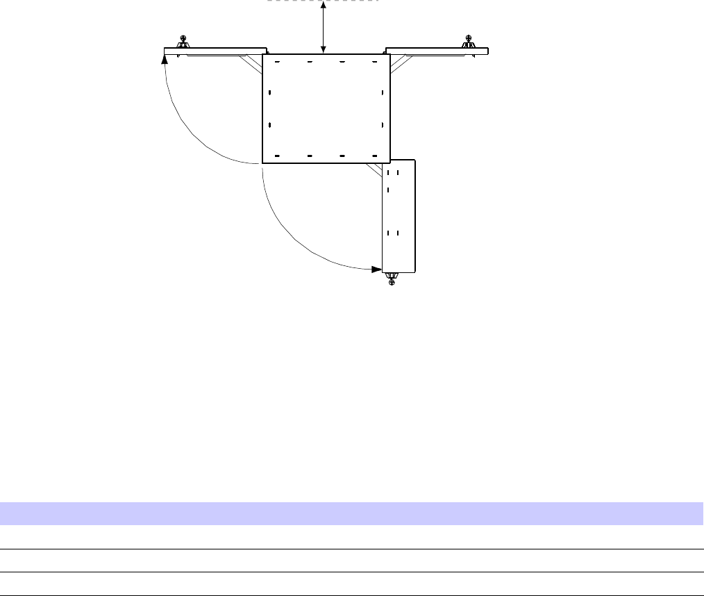
Figure 4 -4 BCU Door Clear ances
ti-cdma-05732.eps
305 mm / 457 mm
Recommended for Fiber Connection
406 mm
Left & Right Door
432 mm
DACS Door
(16 in.)
(17 in.)
(12 in.) / (18 in.)
Conduit Sizes
Refer to T able 4 -1 for the proper conduit sizes.
Table 4 -1 Conduit T ypes and Siz es
No. Designation
Required Size Hole Size
1
Ethernet 1 inch (25.4 mm) 1 inch (25.4 mm)
2
P ower
1–1/4 inch (31.75 mm) 1–1/4 inch (31.75 mm)
3
Fiber Optic
None
Bulkhead connector
Tools and Materials
The following tools and materials or equivalent are required to install the B CU .
4 -10 68P09277A59 -8
PRELIMINARY - UNDER DEVELOPMENT MA Y 2007
Access P oint Hardw are Installation Base Control Unit Installation
•Bucklestrap Cutting T ool (Motorola P/N 6604809N01) for pole mounting bracket assembly
•Safety Glasses
•13/16 Breakaway T orque W rench 38 in -lb (4.3 N -m)
•Chalk
•T ape Measure
•Electrical T ape
•Crescent W rench
•Socket Driver
•Metric or Standard Socket Set for 1/4–in or 3/8–in driver
•P ower Drill
•Concrete and W ood Drill Bits
•Crimp T ool
BCU Wall/Pole Mounting Bracket Assembly Installation
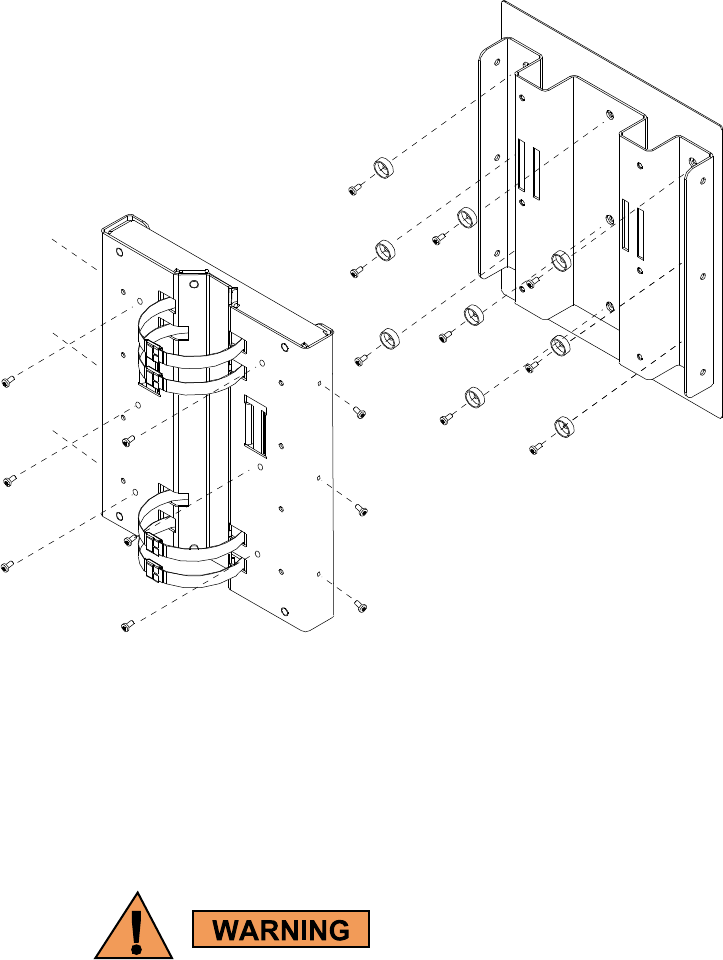
Figure 4 -5 shows the W all/P ole Mounting Bracket and Mounting Bracket Assembly .
68P09277A59 -8 4 -11
PRELIMINARY - UNDER DEVELOPMENT MA Y 2007
Base Control Unit Installation Chapter 4: Access P oint Hardw are Installation
Figure 4 -5 BCU W all/P ole Mounting Br ack et Assembly
ti-cdma-04176.eps
BCU Mounting Bracket Assembly Procedure
Pole Mount
P erform the following procedure to install the P ole/W all Mounting Bracket Assembly on a pole.
Once the BCU is installed, DO NO T use it as a step ladder . It is not designed to support
a person hanging from or standing on top of it.
4 -12 68P09277A59 -8
PRELIMINARY - UNDER DEVELOPMENT MA Y 2007
Access P oint Hardw are Installation Base Control Unit Installation
Procedure 4 -1 Procedure to Install Mounting Br ack et Assembly on a P ole
1
Slide non–buckle end of strap through openings in P ole Mounting Bracket
Assembly .
2
Set P ole Mounting Bracket Assembly with straps at the desired height.
Initial height is determined by customer . The bottom of the B CU
is a minimum of 1 meter from the ground. Adjust P ole/W all
Mounting Bracket Assembly to account for this minimum distance.
3
W rap strap around the pole, slide non–buckle end
through strap loop and around the pole again.
Slide end through strap loop and pull snug.
4
A ttach Bucklestrap Cutting T ool (slide strap through openings in tool,
pull gripper lever to slide strap into spindle head), slide tool towards
buckle. Place cutting tool end of tool as close to the buckle as possible.
The strap can be cut to a more manageable length prior to using
the tool. Bucklestrap Cutting T ool is a ratchet spindle and cutter
in one.
5
Turn spindle clockwise until strap is tight.
Bend the excess strap over tightened strap, cut strap, fold the cut tab into
the buckle, then close buckle.
6
Using the tool bend the strap over towards the buckle.
Remove tool and use a hammer to bend the strap more.
7
Use the hammer to bend buckle tabs over strap.
Use electrical tape to cover over the buckle and straps.
8
P erform step 3 through step 8 , for the remaining straps.
9
If not already attached to B CU , attach Mounting Bracket to B CU using nine
M6 bolts and washers (Refer to Figure 4-5 ). T orque bolts to 30 in–lbs (3.4
N–m).
68P09277A59 -8 4 -13
PRELIMINARY - UNDER DEVELOPMENT MA Y 2007

Base Control Unit Installation Chapter 4: Access P oint Hardw are Installation
Wall Mount
P erform the following procedure to install the P ole/W all Mounting Bracket Assembly on a wall.
Procedure 4 -2 Procedure to Install Mounting Br ack et Assembly on a W all
1
Determine the height at which the Base Control Unit (B CU) will be mounted.
Make sure the wall is capable of supporting the weight, check with Site
Manager .
2
Use the W all Mounting Bracket as a template to layout the nine hole locations.
3
Drill starter holes for the anchor bolts at the locations marked.
4
Secure W all Mounting Bracket to wall using nine
M6 bolts and washers. Refer to Figure 4-5 .
T orque bolts to 30 in-lbs (3.4 N-m).
5
Mount B CU onto W all Mounting Bracket and secure in place.
Installing the BCU
F ollow the steps in Procedure 4 -3 to install the Base Control Unit (B CU).
Procedure 4 -3 Procedure to Install the P ole Mount BCU
1
P erform the procedure for attaching the P ole Mounting Bracket Assembly described in
Procedure 4-1 .
2
Mount the B CU onto the mounting bracket and secure using 12 screws. Refer to Figure 4-5 ).
It is recommended that a minimum of two people attach the B CU on the pole
mounting bracket.
3
B CU is ready for cabling. Proceed to Procedure 4-6 .
P erform Procedure 4 -4 to floor mount the B CU on a concrete pad.
Procedure 4 -4 Installing the BCU Plinth on Concrete
1
P osition the plinth in the desired position.
2
Mark the hole locations on the floor using the plinth as a template.
Continued
4 -14 68P09277A59 -8
PRELIMINARY - UNDER DEVELOPMENT MA Y 2007

Access P oint Hardw are Installation Base Control Unit Installation
Procedure 4 -4 Installing the BCU Plinth on Concrete (Continued)
3
Set aside the plinth and drill holes where hole locations are marked.
4
Ensure that isolation pad is affixed to bottom
of each bracket. Set plinth over holes.
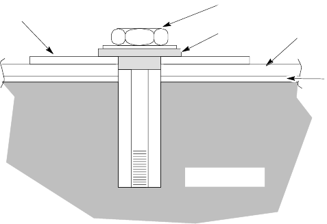
Secure plinth to floor using one flat isolation washer and
one Hilti—Bolt (HSL-3M 8/20) each. T orque bolts to 65 ft-lbs (8.8 N-m)
See Figure 4-7 .
5
V erify that plinth is secured to floor .
6
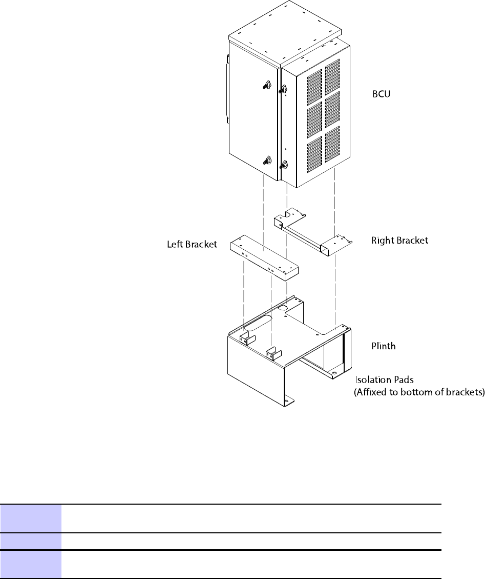
If left and right brackets have not been previously attached to B CU underside,
secure brackets to underside of B CU using four bolts, nuts, and washers each.
T orque bolts to 10 ft-lbs (13.6 N-m). See Figure 4-8
7
If B CU already has left and right brackets attached to its underside, set the
B CU onto the plinth and secure in place using eight screws. T orque the
screws to 10 ft-lbs (13.6 N-m). See Figure 4-8
The B CU can only be set on the plinth in one direction. The
Customer Interface Compartment seats over the notched end of
the plinth.
68P09277A59 -8 4 -15
PRELIMINARY - UNDER DEVELOPMENT MA Y 2007
Base Control Unit Installation Chapter 4: Access P oint Hardw are Installation
Procedure 4 -4 Installing the BCU Plinth on Concrete (Continued)
8
B CU is ready for cabling. Proceed to Procedure 4-6
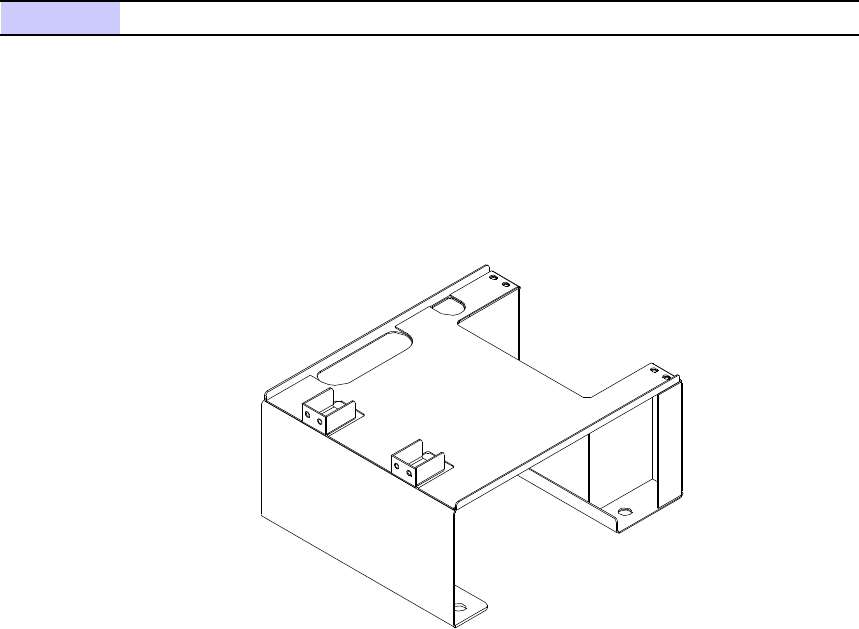
Figure 4 -6 BCU Plinth
ti-cdma-04175.eps
4 -16 68P09277A59 -8
PRELIMINARY - UNDER DEVELOPMENT MA Y 2007
Access P oint Hardw are Installation Base Control Unit Installation
Figure 4 -7 Mounting Bolt Congur ation (Concrete)
ti-cdma-05742.eps
CONCRETE PAD
CONCRETE
HILTI-BOLT
HSL-3M 8/20
LARGE FLAT
WASHER MOUNTING
BRACKET
ISOLATION
PAD
PLINTH
(AFFIXED
TO
BRACKET)
OPTIONAL
ISOLATION
WASHER
68P09277A59 -8 4 -17
PRELIMINARY - UNDER DEVELOPMENT MA Y 2007
Base Control Unit Installation Chapter 4: Access P oint Hardw are Installation
Figure 4 -8 BCU A ttachment to Plinth
ti-cdma-05744.eps
BCU
Plinth
Right Bracket
Left Bracket
Isolation Pads
(Affixed to bottom of brackets)
P erform Procedure 4 -5 to floor mount the B CU on a raised platform or roof .
Procedure 4 -5 Installing the Plinth on a R aised Platform or R oof T op
1
V erify with the Site Manager that the platform/roof top is capable of
supporting the weight of the B CU
2
P osition the plinth in the desired position.
3
Mark the hole locations on the platform or roof top using the plinth as a
template.
Continued
4 -18 68P09277A59 -8
PRELIMINARY - UNDER DEVELOPMENT MA Y 2007

Access P oint Hardw are Installation Base Control Unit Installation
Procedure 4 -5 Installing the Plinth on a R aised Platform or R oof T op (Continued)
4
Set aside the plinth, and drill holes where hole locations are marked.
5
Set plinth over holes.
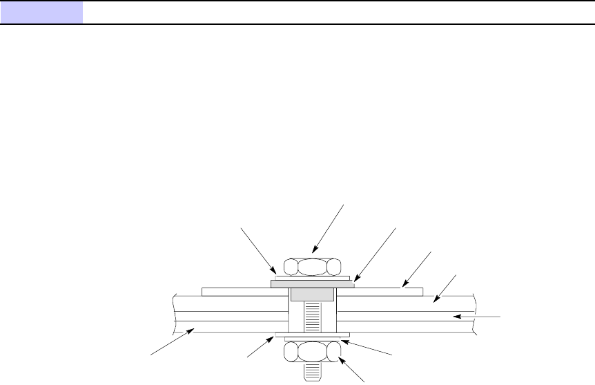
Secure plinth to platform or roof top using one large flat
washer , lock washer , small flat washer , 12M nut, and 12M
bolt each. T orque bolts to 65 ft-lbs (88 N-m) See Figure 4-9 .
If left and right brackets have not been attached to B CU , proceed
to step 6 . Otherwise, proceed to step 7
6
A ttach left and right brackets to underside of B CU using four screws, nuts,
and washers each. T orque screws to 10 ft-lbs (13.6 N-m ). See Figure 4-8 .
Proceed to step 8
7
If B CU already has left and right brackets attached to its underside, set the
B CU onto the plinth and secure in place using eight screws. T orque the
screws to 10 ft-lbs (13.6 N-m).
The B CU can only be set on the plinth in one direction. The
Customer Interface Compartment seats over the notched end of
the plinth.
68P09277A59 -8 4 -19
PRELIMINARY - UNDER DEVELOPMENT MA Y 2007
Base Control Unit Installation Chapter 4: Access P oint Hardw are Installation
Procedure 4 -5 Installing the Plinth on a R aised Platform or R oof T op (Continued)
8
B CU is ready for cabling. Proceed to Procedure 4-6
Figure 4 -9 Mounting Bolt Congur ation (R aised Platform or R oof T op)
ti-cdma-05743.eps
SMALL FLAT
WASHER
ROOFTOP
M12 X 100 BOL T INSULATING WASHER
(OPTIONAL)
LARGE FLAT
WASHER
PLINTH MOUNTING
BRACKET
ISOLATION
PAD
MOUNTING
STRUCTURE
(I BEAM) M12 NUT
LOCK WASHER
SMALL FLAT
WASHER
(AFFIXED TO
BRACKETS)
BCU Cable Installation
P erform the procedure in Procedure 4 -6 to install the B CU cables.
Procedure 4 -6 BCU Cabling Procedures
Continued
4 -20 68P09277A59 -8
PRELIMINARY - UNDER DEVELOPMENT MA Y 2007

Access P oint Hardw are Installation Base Control Unit Installation
Procedure 4 -6 BCU Cabling Procedures (Continued)
The cable access holes are covered. Remove the wing nuts and
covers before routing cables to and from the B CU Customer
Interface Compartment.
1
F or B CU Ground cable installation, B CU ground is located on the side just
behind the Customer Interface compartment door hinge. A ttach the 2–hole
lug and cable to the ground location on the B CU . A ttach other end of ground
cable to system ground bus bar .
2
Ensure the AC (or DC) power is disabled at the source
before attempting to install the AC (or DC) power cabling.
F or AC power cable installation, perform Procedure 4-7 .
F or DC power cable installation, perform Procedure 4-8
3
F or RF Head DC power cable installation, perform Procedure 4-14 .
4
F or Fiber Optic cable installation, perform Procedure 4-16
5
F or RGPS cable installation, perform Procedure B -1 .
F or Local GPS cable installation, perform Procedure 4-10
6
F or Customer Input and Output cable installation, perform Procedure 4-12 .
T o avoid confusion tag the output cables.
7
F or Ethernet cable installation (if available), perform Procedure 4-11
68P09277A59 -8 4 -21
PRELIMINARY - UNDER DEVELOPMENT MA Y 2007

AC or DC P ower Cabling Installation Chapter 4: Access P oint Hardw are Installation
AC or DC Power Cabling Installation■■■■■■■■■■■■■■■■■■■■■■■■■■■■■■■■■■■■■■■■■■■■■■■■■■■■■■■■■■■■■■
■
■
Objective
This section contains the procedure for installing the AC power cable.
This equipment uses dangerous v oltages and is capable of causing death. Use extreme
caution when handling and testing this equipment. Earth connection is essential before
connecting the power due to the presence of high earth leakage current.
AC Cable Description
Cable E as listed in T able 3 -1 is required for this installation.
The minimum bend radius for this cable is 90 mm.
Tools Required
The following tools are required to install the AC power cables.
•No . 2 Blade screw driver
AC Power Connection Procedure
F ollow the steps in Procedure 4 -7 to connect a 100/240 V AC , Single Phase AC power cable to
the Base Control Unit (B CU). The AC power cable will be routed through one and one -half inch
conduit to the appropriate access hole on the underside of the B CU . The circuit breaker rating
ofr the AC Surge Protect is 25 A.
Branch Circuit protection to be provided during installation. A Single pole 25A rated circuit
breaker or adequately rated fuse shall be used for nominal 110/240 V AC installations." "F or
supply connections, use wires suitable for at least 75°C" "Unit is intended for installation in
Restricted Access Locations"
4 -22 68P09277A59 -8
PRELIMINARY - UNDER DEVELOPMENT MA Y 2007
Access P oint Hardw are Installation AC or DC P ower Cabling Installation
This equipment is designed to permit the connection of the earthed conductor of the
DC supply circuit to the earthing conductor at the equipment. If this connection is
made, all of the following conditions must be met:
•This equipment shall be connected to directly to the DC supply system earthing
electrode conductor or to a bonding jumper from an earthing terminal bar or bus
to which the DC supply system earthing electrode conductor is connected.
•This equipment shall be located in the same immediate area (such as, adjacent
cabinets) as an y other equipment that has a connection between the earthed
conductor of the same d.c. supply circuit and the earthing conductor , and also
the point of earthing of the DC system. The DC system shall not be earthed
elsewhere.
•The DC supply source is to be located within the same premises as the equipment.
•S witching or disconnecting devices shall not be in the earthed circuit conductor
between the d.c. source and the point of connection of the earthing.
F or supply connections, use wires suitable for at least 75°C .
Floating Supply voltage should not exceed 60 VDC for DC powered equipment.
Unit is intended for installation in Restricted Access Locations
Branch Circuit protection to be provided during installation. A single pole 50A rated circuit
breaker or adequately rated fuse shall be used for nominal -48 VDC installations. A Single
pole 80A rated circuit breaker or adequately rated fuse shall be used for nominal +27 VDC
installations.
Procedure 4 -7 Procedure to Install AC P ower Cable
1
Ensure that AC power at the source is disabled before handling cable.
AC power cables are supplied by the customer and should already
have been laid out at the site.
2
If not already done, route AC power cables through conduit to B CU Customer
Interface compartment.
3
In the B CU Customer Interface compartment, open the AC Surge Module
cover by loosening two captive screws. AC Surge Module cover is hinged.
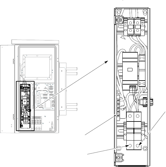
4
Loosen screws on AC power terminal block. Insert AC power cables into
GROUND ,LINE and NEUTRAL and tighten screws. See Figure 4-10
Ensure a good connection.
5
Close AC Surge Module cover and secure by tightening two captive screws.
6
If required, enable AC power at the source.
68P09277A59 -8 4 -23
PRELIMINARY - UNDER DEVELOPMENT MA Y 2007
AC or DC P ower Cabling Installation Chapter 4: Access P oint Hardw are Installation
Figure 4 -10 BCU AC P ower Connection
ti-cdma-04182.eps
Neutral Connection
Line Connection
Ground
Connection
DC Cable Description
Cable M as listed in T able 3 -1 is required for this installation.
DC Power Connection Procedure
F ollow the steps in Procedure 4 -8 to connect a nominal +27 or —48 VDC power cable to the
Base Control Unit (B CU). The DC power cable will be routed through one and one -half inch
conduit to the appropriate access hole on the underside of the B CU .
The circuit breaker rating for the +27 DC Surge Protect is 80 A. The circuit breaker rating for
the —48 V DC Surge Protect is 50 A.
Procedure 4 -8 Procedure to Install DC P ower Cable
Continued
4 -24 68P09277A59 -8
PRELIMINARY - UNDER DEVELOPMENT MA Y 2007
Access P oint Hardw are Installation AC or DC P ower Cabling Installation
Procedure 4 -8 Procedure to Install DC P ower Cable (Continued)
1
Ensure that DC power at the source is disabled before handling cable.
DC power cables are supplied by the customer and should already
have been laid out at the site.
2
If not already done, route DC power cables through conduit to B CU Customer
Interface compartment.
3
In the B CU Customer Interface compartment, open the DC Surge Module
cover by loosening two captive screws. DC Surge Module cover is hinged.
4
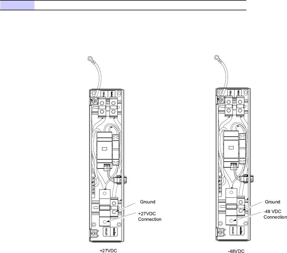
Loosen screws on DC power terminal blocks. Insert DC
power cables into +27VDC and RETURN or —48VDC
and +0V RETURN and tighten screws. See Figure 4-11
Ensure a good connection.
5
Close DC Surge Module cover and secure by tightening two captive screws.
68P09277A59 -8 4 -25
PRELIMINARY - UNDER DEVELOPMENT MA Y 2007
AC or DC P ower Cabling Installation Chapter 4: Access P oint Hardw are Installation
Procedure 4 -8 Procedure to Install DC P ower Cable (Continued)
6
If required, enable DC power at the source.
Figure 4 -11 BCU DC P ower Connection
ti-cdma-05745.eps
Ground
-48VDC
+27VDC
+27VDC
Connection
Ground
-48 VDC
Connection
4 -26 68P09277A59 -8
PRELIMINARY - UNDER DEVELOPMENT MA Y 2007

Access P oint Hardw are Installation Local GPS Cabling Installation
Local GPS Cabling Installation■■■■■■■■■■■■■■■■■■■■■■■■■■■■■■■■■■■■■■■■■■■■■■■■■■■■■■■■■■■■■■
■
■
Objective
The objective of this procedure is to install the Local (RF) Global P ositioning System (RF GPS)
cabling.
Tools and Materials
provides the quantities and descriptions of the cables.
•5/16 Breakaway T orque W rench 9 -in. lb
•Adjustable T orque R atchet with metric socket set
•Flathead screwdriver
•N -SMA Adapter
Cable Description
Cable K as listed in T able 3 -1 is required for installation.
Surge Arrestor Installation
P erform the procedure in Procedure 4 -9 to install the surge arrestor .
Procedure 4 -9 Procedure to Install Surge Arrestor
1
Open Base Control Unit (B CU) Customer Interface Compartment.
2
V erify that surge arrestor is already installed. If not, then remove surge
arrestor from kit.
3
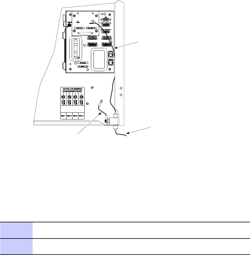
Install surge arrestor in the right side bottom of Customer Interface
Compartment, see Figure 4-13 .
4
A ttaching the ground cable is optional.
If not provided, perform the following to make
the ground cable for the surge arrestor .
Get two lug nuts.
Continued
68P09277A59 -8 4 -27
PRELIMINARY - UNDER DEVELOPMENT MA Y 2007
Local GPS Cabling Installation Chapter 4: Access P oint Hardw are Installation
Procedure 4 -9 Procedure to Install Surge Arrestor (Continued)
Crimp one end each of a 6 – 8 inch long, #6 A WG cable to the lug nuts.
5
Unscrew knurled nut from surge arrestor and attach ground lug.
Screw knurled nut into surge arrestor and hand tighten.
A ttach other end of ground cable to the threaded ground
connection just above the surge arrestor . See Figure 4-13 .
A ttach self locking nut to secure ground connection to B CU .
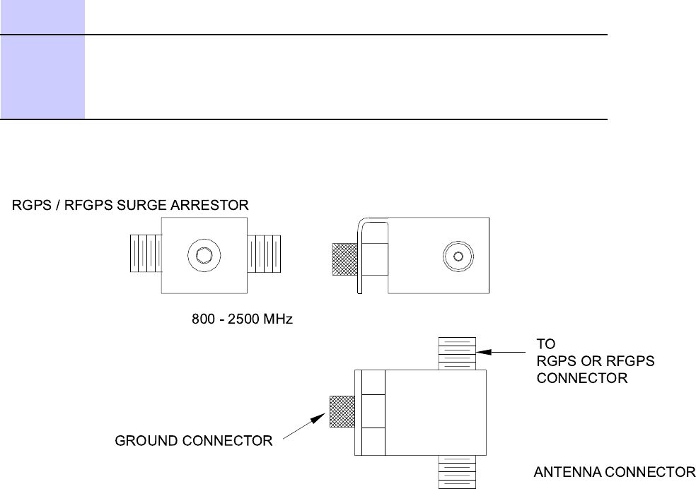
Figure 4 -12 Surge Arrestor
ti-cdma-05829.eps
TO
RGPS OR RFGPS
CONNECT OR
ANTENNA CONNECT OR
GROUND CONNECT OR
RGPS / RFGPS SURGE ARREST OR
800 - 2500 MHz
4 -28 68P09277A59 -8
PRELIMINARY - UNDER DEVELOPMENT MA Y 2007
Access P oint Hardw are Installation Local GPS Cabling Installation
Figure 4 -13 Surge Arrestor Orientation and Ground Location
ti-cdma-05831.eps
RF -GPS Cable
To Antenna
Ground Cable
(Optional Connection)
Installing Local GPS Antenna and Cable
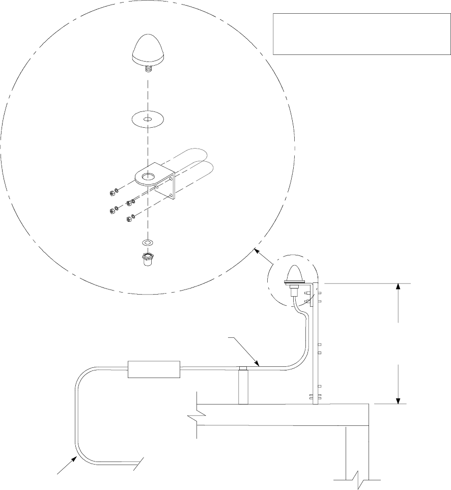
Figure 4 -14 shows the components of the Local GPS . The Local GPS is connected to the B CU
via the Customer Interface compartment.
Procedure 4 -10 Procedure for Installing Local GPS Antenna and Cabling
1
Determine the mounting location (see Local GPS Mounting Considerations,
T able 3-8 ).
2
Install the mounting kit at the Local GPS location of choice. Use the
appropriate mounting bolts for mounting surface.
Continued
68P09277A59 -8 4 -29
PRELIMINARY - UNDER DEVELOPMENT MA Y 2007
Local GPS Cabling Installation Chapter 4: Access P oint Hardw are Installation
Procedure 4 -10 Procedure for Installing Local GPS Antenna and Cabling (Continued)
3
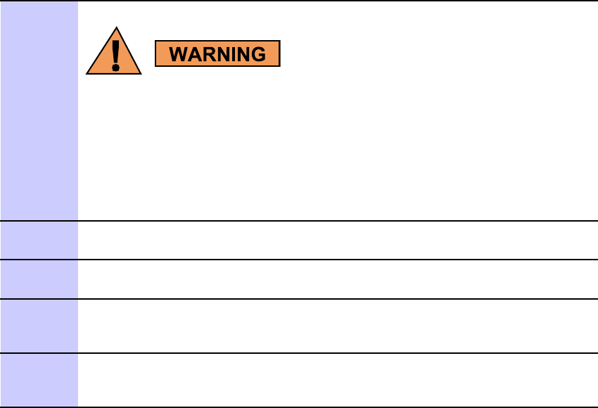
The roof structure on which the mounting pole is attached should be
v eried b y a qualied structur al engineer for the weight of the Local
GPS engine and mounting hardw are or under adv erse conditions
for the installation area
Mounting the Local GPS antenna and hardware to an inadequate roof surface
and/or using inadequate installation methods can result in serious injury .
4
A ttach the Local GPS antenna assembly to the mounting bracket and secure
washer and custom nut supplied. See Figure 4-14
5
A ttach the grounding kit to the mounting pole with u-bolts and secure using
washers and nuts supplied. See Figure 4-14
6
Connect one (1) N connector of the 50 feet superflex cable to the N jack of the
RF GPS antenna cable (K) and route the other end of the cable down to the
B CU . Make allowances for strain relief .
7
Route the cable to the underside of the B CU to surge
arrestor connector (in Customer Interface Compartment).
Connect RF GPS cable between RF GPS Module and top of surge arrestor .
Continued
4 -30 68P09277A59 -8
PRELIMINARY - UNDER DEVELOPMENT MA Y 2007
Access P oint Hardw are Installation Local GPS Cabling Installation
Procedure 4 -10 Procedure for Installing Local GPS Antenna and Cabling (Continued)
Figure 4 -14 Local GPS Installation and Components Diagr am
ti-cdma-04199.eps
ANTENNA
(GCNTM20A3A)
RUBBER PAD
(P/O ANTENNA)
MOUNTING
BRACKET
(MNT62312B1)
WASHER P/O ANTENNA
CUSTOM HEX NUT M36 MM
P/O ANTENNA
(SEE NOTE 1)
(FSJ4--50B)
TO BCU
ROOF
NOTE:
1. TOTALWEIGHT FOR GPS ANTENNA
ASSEMBLY -- 0.65 LBS
E/K
K
(CGDSVXL550)
U--BOLTS P/O
MOUNTING
BRACKET
NUTS AND LOCK
WASHERS
P/O MOUNTING
BRACKET
ANTENNA IS DESIGNED FOR A 1--IN DIA.
NOMINALPIPE.
THE ANTENNA CAN BE INSTALLED ON A
3/4--IN DIA. PIPE,HOWEVER,NYLON
SPACERS ARE REQUIRED TO TAKE UP
THE SLACK ON THE U--BOLT.
SPACERS ARE CUSTOMER SUPPLIED
AND IT IS RECOMMENDED THAT THEY
MEET THE FOLLOWING REQUIREMENTS:
NYLON,1/2--IN LG,0.0742--IN OD AND
0.250--IN ID. QTY. OF 4.
ADJUSTABLE FROM
33.5 TO 47--IN.
N CONNECTOR
LA
68P09277A59 -8 4 -31
PRELIMINARY - UNDER DEVELOPMENT MA Y 2007
Ethernet Cabling Installation Chapter 4: Access P oint Hardw are Installation
Ethernet Cabling Installation■■■■■■■■■■■■■■■■■■■■■■■■■■■■■■■■■■■■■■■■■■■■■■■■■■■■■■■■■■■■■■
■
■
Objective
This section contains the procedure for installing the Ethernet cables.
Cable Description
Cable J as listed in T able 3 -1 is required for installation.
Installing Ethernet Cables
F ollow the steps in Procedure 4 -11 to install the ethernet cables.
Procedure 4 -11 Procedure to Install Ethernet Cables
1
If not already done
, remove conduit plug at the bottom of the B CU .
2
If Ethernet cables are not present, route
one end to Site T ermination Equipment.
If Ethernet cables are present, route them through conduit
and through access hole in the bottom of the B CU .
3
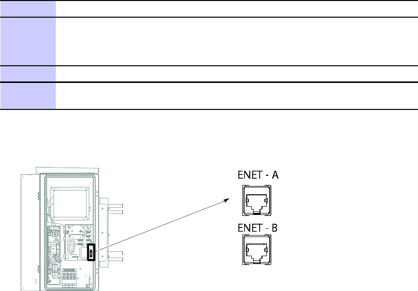
Insert cable connectors in the sockets labeled ENET A and ENET B.
4
If there are no more cables to connect close and lock Customer Interface
compartment.
Figure 4 -15 Ethernet Cable Connection
ti-cdma-04184.eps
ENET - A
ENET - A
ENET - B
ENET - B
4 -32 68P09277A59 -8
PRELIMINARY - UNDER DEVELOPMENT MA Y 2007
Access P oint Hardw are Installation Customer Input/Output Cabling Installation
Customer Input/Output Cabling Installation■■■■■■■■■■■■■■■■■■■■■■■■■■■■■■■■■■■■■■■■■■■■■■■■■■■■■■■■■■■■■■
■
■
Objective
This section contains the procedures for installing the Customer Defined Input/Output cables.
Cable Descriptions
Cable F as listed in T able 3 -1 is required for installation.
Customer Input and Output Connector Pinouts
This section contains the procedures for installing the Customer Defined Input/Output cables.
The CDI/CDO cables will be routed through one inch conduit to the access hole on the underside
of the B CU .
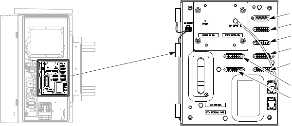
Figure 4 -16 Customer Dened Input and Output Connectors
ti-cdma-04185.eps
RGD
CUST. OUTPUT 1-2
CUST. OUTPUT 3-4
CUST. INPUT 5-8
CUST. INPUT 13-16
CUST. INPUT 1- 4
CUST. INPUT 9-12
Customer Dened Input/Output Cable Installation
F ollow the procedure in Procedure 4 -12 to install the Customer Defined Input/Output Cables
Continued
68P09277A59 -8 4 -33
PRELIMINARY - UNDER DEVELOPMENT MA Y 2007