Nokia Solutions and Networks T7HN1 2.5 GHz Diversity Access Point User Manual users manual 5
Nokia Solutions and Networks 2.5 GHz Diversity Access Point users manual 5
Contents
- 1. users manual 1
- 2. users manual 2
- 3. users manual 3
- 4. users manual 4
- 5. users manual 5
users manual 5

Customer Input/Output Cabling Installation Chapter 4: Access P oint Hardw are Installation
Procedure 4 -12 Procedure to Install the Customer Dened Input/Output Cables
1
If not already open, open the Customer Interface Compartment.
If not already done, remove conduit plug from access hole.
2
Route the Customer Defined Input (CDI) Cable 1–2 through conduit to the
underside of the B CU , through the access hole, and up to the connector
labeled
CUST . INP UT 1–2
3
P erform step 2 for CDI Cable 3–4.
4
Route the Customer Defined Output (CDO) Cable 1–4 through conduit to
the underside of the B CU , through the access hole, and up to the connector
labeled
CUST . OUTP UT 1–4
5
P erform step 4 for CDO Cables 5–8, 9–12, and 13–16.
6
Ensure a good connection.
Close and lock Customer Interface compartment.
4 -34 68P09277A59 -8
PRELIMINARY - UNDER DEVELOPMENT MA Y 2007
Access P oint Hardw are Installation Div ersit y Access P oint (DAP) RF Head Assembly Installation
Diversity Access Point (DAP) RF Head Assembly
Installation
■■■■■■■■■■■■■■■■■■■■■■■■■■■■■■■■■■■■■■■■■■■■■■■■■■■■■■■■■■■■■■
■
■
Overview
This section contains the procedures for installing the Diversity Access P oint RF Head Assembly
which is comprised of the RF Head and antenna radome. Refer to Figure 1 -2 for an overall
view of the DAP .
DAP RF Head
Refer to Figure 1 -4 for the major components of the DAP RF Head.
Electrical Requirements
The RF Head is designed to use 40 to 59 VDC (nominal +54 VDC) supplied through the Base
Control Unit (B CU).
Environmental
The operational temperature range for the RF Head is –20 to +55 degrees centigrade.
Dimensions and Weight
•Dimension: 228.6 mm (9 in) Wx 712 mm (28 in) Hx 406.4 mm (16 in) D
•W eight: 25.4 kg (56 lbs)
The dimension measurements do not include connectors, hinges, handles, or latches.
Conduit Sizes
Refer to T able 4 -2 for conduit sizes.
68P09277A59 -8 4 -35
PRELIMINARY - UNDER DEVELOPMENT MA Y 2007

Div ersit y Access P oint (DAP) RF Head Assembly Installation Chapter 4: Access P oint Hardw are Installation
Table 4 -2 Conduit R equirements
No. Designation
Required Size
1
P ower
1–1/4 inch
2
Fiber Optic
None
Tools and Materials
•Mounting Bracket Assembly
•U -bolts
•Set of metric sockets (3/8–in or 1/4–in drivers)
•Set of standard sockets (3/8–in or 1/4–in drivers)
•Socket 3/8–in or 1/4–in driver
•T orque Driver
•Cordless P ower Driver
•Ground Lug
•Crimp T ool
•T30 T orx Screw Driver
•Adjustable Crescent W rench
•Tie -wraps of varying lengths
U -Bolt Specications
The U -bolt is
supplied by the Customer
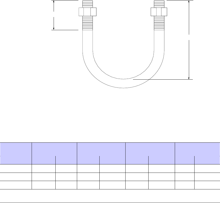
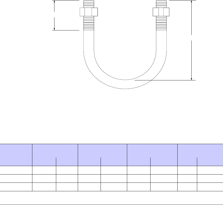
. Reference Figure 4 -17 and to determine the proper
U -bolt to use. P ole mounting bracket is designed to use 3/8–inch hardware.
4 -36 68P09277A59 -8
PRELIMINARY - UNDER DEVELOPMENT MA Y 2007
Access P oint Hardw are Installation Div ersit y Access P oint (DAP) RF Head Assembly Installation
Figure 4 -17 U -Bolt Sizing
ti-cdma-05727.eps
C
B
Table 4 -3 DAP U -Bolt Sizing
Nominal
Pipe Size
Pipe OD
Minimum Dimension
B
Maximum Dimension
B
Minimum
Dimension C
(in) (in) (mm) (in) (mm) (in) (mm) (in) (mm)
2 2.375 60.33 3.886 98.70 4.886 124.10 0.6 15
2.5 2.875 73.03 4.429 112.50 5.429 137.90 0.6 15
3 3.500 88.90 5.098 129.50 6.098 154.90 0.6 15
Dimension B maximum allowable increase is 1 inch (25.4 mm). This will result in a
corresponding increase in dimension C in order to maintain proper clamping force
RF Head Assembly Installation Procedure
F ollow the steps in Procedure A -1 to install the RF Head Assembly including main Support
Bracket Assembly .
68P09277A59 -8 4 -37
PRELIMINARY - UNDER DEVELOPMENT MA Y 2007
Div ersit y Access P oint (DAP) RF Head Assembly Installation Chapter 4: Access P oint Hardw are Installation
The following procedure is based on the RF Head arriving already assembled. If the
RF head must be assembled at the site then follow the procedure in Appendix A
Alternate RF Head Installation Procedure .
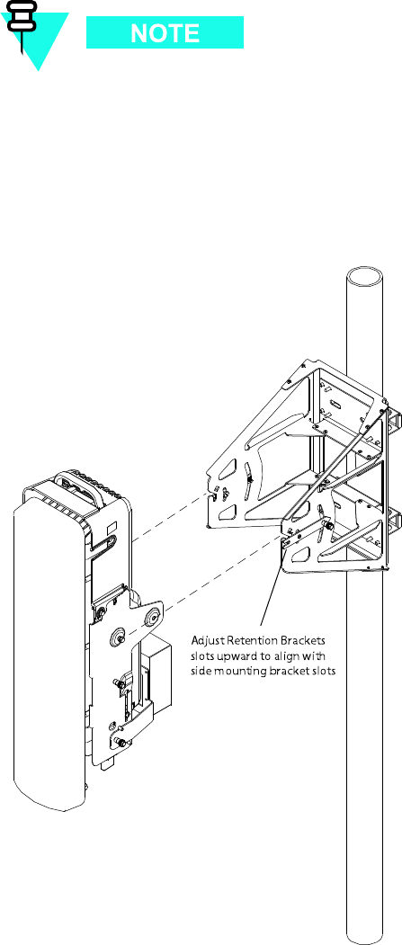
Figure 4 -18 RF Head Assembly
ti-cdma-05725.eps
Adjust Retention Brackets
slots upward to align with
side mounting bracket slots
Procedure 4 -13 Procedure to Install RF Head Assembly
Continued
4 -38 68P09277A59 -8
PRELIMINARY - UNDER DEVELOPMENT MA Y 2007
Access P oint Hardw are Installation Div ersit y Access P oint (DAP) RF Head Assembly Installation
1
From RF Head Main Support Bracket Assembly , remove nuts and washers
from both ends of the U -bolts.
2
Set RF Head Main Support Bracket Assembly at the desired location on
the pole.
3
Slide first U -bolt around pole and through top slots of RF Head Main
Support Bracket Assembly . Slide washers over threaded ends of U -bolt.
Thread nuts on U -bolt and hand tighten.
4
Slide second U -bolt around pole and through bottom slots of Main
Support Bracket Assembly . Slide washers over threaded ends of U -bolt.
Thread nuts on U -bolt and hand tighten.
5
Align Main Support Bracket Assembly on pole to desired direction and
tighten nuts using a socket wrench. T orque nuts to 24. ft-lbs (32.5 N-m).
6
On the inside of the Base Control Unit (B CU) Customer Interface
Compartment are color coded stickers and matching tie-wraps.
The colors are matched to the RF Head DC power cables. The
colors are as follows:
•RFU 1 = RED
•RFU 2 = BL UE
•RFU 3 = YELLOW
•RFU 4 = GREEN
Remove the appropriate color sticker and apply it to the
underside of the RF Head. Use the appropriate tie-wraps to
identify the DC power cables and the Fiber Optic cables.
F or Example:
The first RF Head used would have the power connector identified with the
RED sticker , and the power and fiber cables would be tagged with
the RED tie-wraps.
7
A ttach RF cables between R adome and RF Head. T orque nuts to 38 in-lbs
(4.3 N-m).
8
A ttach solar shield.
Insert mushroom head knobs near bottom of shield
into keyhole slots on sides of mounting bracket.
Slide solar shield into position over handle
and into slots on top of mounting bracket.
Tighten screws to secure shield to brackets.
9
Prepare the RF Head for hoisting.
A ttach carabiner to handle of RF Head.
Use the block and tackle to carefully hoist (so cables will not be damaged)
the RF Head Assembly up to the tower . Proceed to step 10 .
Continued
68P09277A59 -8 4 -39
PRELIMINARY - UNDER DEVELOPMENT MA Y 2007

Div ersit y Access P oint (DAP) RF Head Assembly Installation Chapter 4: Access P oint Hardw are Installation
Procedure 4 -13 Procedure to Install RF Head Assembly (Continued)
10
Slide the RF Head into the side mounting bracket and retention bracket
slots. See Figure A-3
1 1
Ensure that the RF Head is properly mounted and its movement
is not obstructed. T o adjust the tilt (up/down angle) loosen two
M6 screws on each side of unit using a 10 mm socket or crescent
wrench. R ange of motion is 25 degrees from horizontal. The
retention bracket serves as an indicator of the tilt in degrees.
When RF Head is set at the desired position, tighten captive
bolts on retention bracket. T orque bolts to 45 in-lbs (5.0 N-m).
Tighten captive screws at pivot on each side of unit to
secure RF Head. T orque screws to 45 in-lbs (5.0 N-m).
12
Proceed to Procedure 4-14 for RF Head DC P ower Cable connection
procedure.
4 -40 68P09277A59 -8
PRELIMINARY - UNDER DEVELOPMENT MA Y 2007

Access P oint Hardw are Installation RF Head DC P ower Cabling Installation
RF Head DC Power Cabling Installation■■■■■■■■■■■■■■■■■■■■■■■■■■■■■■■■■■■■■■■■■■■■■■■■■■■■■■■■■■■■■■
■
■
Objective
This section contains the procedure for installing the RF Head DC power cables.
DC Cable Description
Cable G listed in T able 3 -1 is required for installation
Tools Required
The following tools are required to install the DC P ower cables.
RF Head DC Power Cable Installation
F ollow the steps in Procedure 4 -14 to install the RF Head DC P ower Cables.
Procedure 4 -14 Procedure to Install RF Head DC P ower Cables
1
If not already open, open the B CU Customer Interface compartment.
2
Before routing DC power cable, verify that it is properly color coded. If more
than one RF Head in use, ensure that they are all properly color coded. The
colors are as follows:
•RFU 1 = RED
•RFU 2 = BL UE
•RFU 3 = YELLOW
•RFU 4 = GREEN
Color coded labels and tie-wraps can be found on the compartment
side of the door of the B CU Customer Interface Compartment.
Tie-wraps should be attached near the DC P ower cable connector .
Continued
68P09277A59 -8 4 -41
PRELIMINARY - UNDER DEVELOPMENT MA Y 2007
RF Head DC P ower Cabling Installation Chapter 4: Access P oint Hardw are Installation
Procedure 4 -14 Procedure to Install RF Head DC P ower Cables (Continued)
3
Route the DC P ower cables through conduit up to the tower . Bundle and
secure the cables (if RF Head is not present) or connect to the appropriate
RF Head.
Connect or disconnect the cable b y turning the coupling nut. Do
not try to connect or disconnect the cable b y turning the cable or
other attaching components.
4
Proceed to Procedure 4-16 for the Fiber Optic Cable connection procedure.
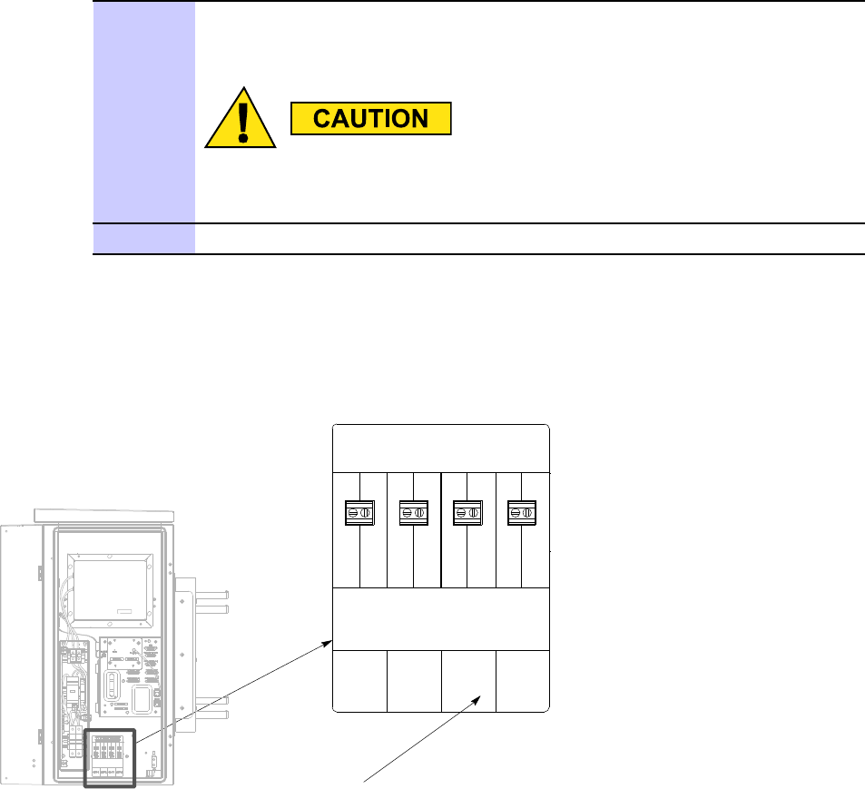
Figure 4 -19 Base Control Unit RF Head DC P ower Connection
ti-cdma-04183.eps
RFU 1, RFU 2, RFU 3, RFU4
CAUTION LIVE TERMINALS
CAUTION PRIOR TO INSTALLATION/REMOVAL OF WIRE TO TERMINAL
BLOCK. ASSOCIATED CIRCUIT BREAKER TO BE DISENGAGED
+54VDC
RETURN
+54VDC
RETURN
+54VDC
RETURN
+54VDC
RETURN
RFU 1 RFU 3 RFU 4RFU 2
4 -42 68P09277A59 -8
PRELIMINARY - UNDER DEVELOPMENT MA Y 2007
Access P oint Hardw are Installation Antenna Cabling Installation
Antenna Cabling Installation■■■■■■■■■■■■■■■■■■■■■■■■■■■■■■■■■■■■■■■■■■■■■■■■■■■■■■■■■■■■■■
■
■
Objective
This section contains the procedure for installing the antenna cables.
Installing Antenna Cables
The antenna cables between RF Head and radome can be installed before or after the RF Head
Assembly is mounted on the pole.
68P09277A59 -8 4 -43
PRELIMINARY - UNDER DEVELOPMENT MA Y 2007

RF Head Ground Cabling Installation Chapter 4: Access P oint Hardw are Installation
RF Head Ground Cabling Installation■■■■■■■■■■■■■■■■■■■■■■■■■■■■■■■■■■■■■■■■■■■■■■■■■■■■■■■■■■■■■■
■
■
The RF Head comes with a ground lug attached, but no ground wire.
F ollow the procedure in
Procedure 4 -15 RF Head Ground Cable Installation
1
Use a 10 mm socket wrench to loosen ground lug captive screws on RF Head.
2
Remove ground lug.
3
Slide a 6 A WG wire into the ground lug.
Crimp ground lug onto wire.
V erify that 6 A WG wire is secure within ground
lug.
4
Reattach ground lug onto RF Head.
Use a 10 mm socket wrench to tighten
captive screws. T orque to 45 in-lbs (5.0 N-m).
Secure opposite other end of ground wire to tower ground.
4 -44 68P09277A59 -8
PRELIMINARY - UNDER DEVELOPMENT MA Y 2007
Access P oint Hardw are Installation Fiber Optic Cabling Installation
Fiber Optic Cabling Installation■■■■■■■■■■■■■■■■■■■■■■■■■■■■■■■■■■■■■■■■■■■■■■■■■■■■■■■■■■■■■■
■
■
Objective
This section contains the procedure for installing the fiber optic cables.
Cable Description
Cable H as listed in T able 3 -1 is required for installation.
The minimum bend radius for this cable is 90 mm.
Procedure 4 -16 Procedure to Install Fiber Optic Cables
1
Before routing the Fiber Optic cable(s) up the
tower , verify that it is properly color coded.
Red — RF Head 1
Blue — RF Head 2
Y ellow — RF Head 3
Green — RF Head 4
Color coded labels and tie-wraps can be found on the compartment
side of the door of the B CU Customer Interface compartment.
2
Connect the Fiber Optic cables to the bulkhead feedthroughs (FIBER) on
the underside of the Base Control Unit (B CU). T orque connector nut to 38
in-lbs (4.3 N-m).
Connect or disconnect the cable b y turning the coupling nut. Do
not try to connect or disconnect the cable b y turning the cable or
other attaching components.
3
Route the cable(s) up the tower(s), bundle and secure
to tower (if RF Head is not present) or connect to the
68P09277A59 -8 4 -45
PRELIMINARY - UNDER DEVELOPMENT MA Y 2007

Fiber Optic Cabling Installation Chapter 4: Access P oint Hardw are Installation
Procedure 4 -16 Procedure to Install Fiber Optic Cables (Continued)
appropriate RF Head. T wist coupling nut until it stops (detent).
Use tie-wraps or appropriate clamps to secure cable to tower .
4 -46 68P09277A59 -8
PRELIMINARY - UNDER DEVELOPMENT MA Y 2007

C h a p t e r
5
Optional Equipment
■■■■■■■■■■■■■■■■■■■■■■■■■■■■■■■■■■■■■■■■■■■■■■■■■■■■■■■■■■■■■■
■
■
■
■
68P09277A59 -8 5 -1
MA Y 2007 PRELIMINARY - UNDER DEVELOPMENT
R ack Mounting Chapter 5: Optional Equipment
Rack Mounting
■■■■■■■■■■■■■■■■■■■■■■■■■■■■■■■■■■■■■■■■■■■■■■■■■■■■■■■■■■■■■■
■
■
Rack Mount Instructions
to be followed in all rack mount installations for all voltage range equipment (+27 VDC , -48
VDC , and A/C):
1. Elevated Operating Ambient - If installed in a closed or multi -unit rack assembly , the
operating ambient temperature of the rack environment may be greater than room
ambient. Therefore, consideration should be given to installing the equipment in an
environment compatible with the maximum ambient temperature of the equipment (55C)
2. Reduced Air Flow - Installation of the equipment in a rack should be such that the amount
of air flow required for safe operation of the equipment is not compromised.
3. Mechanical Loading - Mounting of the equipment in the rack should be such that a
hazardous condition is not achieved due to uneven mechanical loading.
4. Circuit Overloading - Consideration should be given to the connection of the equipment to
the supply circuit and the effect that overloading of the circuits might have on over current
protection and supply wiring. Appropriate consideration of equipment nameplate ratings
should be used when addressing this concern.
5. Reliable Earthing - Reliable earthing of rack -mounted equipment should be maintained.
P articular attention should be given to supply connections other than direct connections to
the branch circuit (e.g. use of power strips).
5 -2 68P09277A59 -8
PRELIMINARY - UNDER DEVELOPMENT MA Y 2007
Access P oint Hardw are Installation Optional Band P ass Filters
Optional Band Pass Filters■■■■■■■■■■■■■■■■■■■■■■■■■■■■■■■■■■■■■■■■■■■■■■■■■■■■■■■■■■■■■■
■
■
Overview
This chapter contains general information and procedures for installing optional equipment.
Band pass filters are available as optional equipment to accommodate customers with specific
band allocations.
68P09277A59 -8 5 -3
PRELIMINARY - UNDER DEVELOPMENT MA Y 2007
Optional Band P ass Filters Chapter 5: Optional Equipment
Filter Requirements
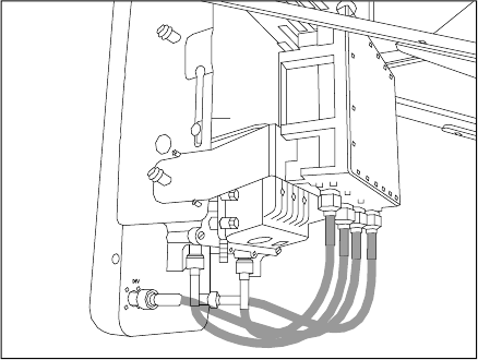
W eight and Dimensions The band pass filter(s) used should meet the following
requirements:
•W eight: 1.6 kg (3.5 lbs)
•Dimensions: 50 mm (2 in) Wx 150 mm (6 in) Hx 100 mm (4 in) D.
Figure 5 -1 Band P ass Filter
Filter Mounting Figure 5 -2 shows the optimal mounting position on the RF Carrier Unit
(RFCU). The filters are mounted such that cable lengths are kept to a minimum. There is a
mounting bracket already on the RF Head Assembly for the optional filter .
Figure 5 -2 Filter Mounting
ti-cdma-05748.eps
DIV
5 -4 68P09277A59 -8
PRELIMINARY - UNDER DEVELOPMENT MA Y 2007
Access P oint Hardw are Installation Motorola Stabilit y Oscillator (MSO)
Motorola Stability Oscillator (MSO)■■■■■■■■■■■■■■■■■■■■■■■■■■■■■■■■■■■■■■■■■■■■■■■■■■■■■■■■■■■■■■
■
■
Overview
The Motorola Stability Oscillator (MSO) is available as optional equipment to accommodate
customers that want this backup timing module.
68P09277A59 -8 5 -5
MA Y 2007 PRELIMINARY - UNDER DEVELOPMENT
Motorola Stabilit y Oscillator (MSO) Chapter 5: Optional Equipment
5 -6 68P09277A59 -8
PRELIMINARY - UNDER DEVELOPMENT MA Y 2007

C h a p t e r
6
What’s Next and Cleanup■■■■■■■■■■■■■■■■■■■■■■■■■■■■■■■■■■■■■■■■■■■■■■■■■■■■■■■■■■■■■■
■
■
■
■
68P09277A59 -8 6 -1
MA Y 2007 PRELIMINARY - UNDER DEVELOPMENT
What ’ s Next Chapter 6: What ’ s Next and Cleanup
What’s Next■■■■■■■■■■■■■■■■■■■■■■■■■■■■■■■■■■■■■■■■■■■■■■■■■■■■■■■■■■■■■■
■
■
Introduction
Optimization is the next procedure you should perform. There are two things left to do before
you begin the optimization:
1. Clean up the site
2. Fill out the installation completion checklist
Clean Up Site
Clean up the site by following the information given in the
Site Cleanup
area in this chapter .
Fill Out Checklist
A fter the site is cleaned up, fill out the installation completion checklist. This checklist is located
in the
Installation Completion Checklist
area of this chapter .
Optimize the System
Optimize the system by following the procedures given in the appropriate optimization manual.
The hardware installation does not include card placement and turning on power . These things
and more are covered in the appropriate optimization manual.
6 -2 68P09277A59 -8
PRELIMINARY - UNDER DEVELOPMENT MA Y 2007
Access P oint Hardw are Installation Site Cleanup
Site Cleanup
■■■■■■■■■■■■■■■■■■■■■■■■■■■■■■■■■■■■■■■■■■■■■■■■■■■■■■■■■■■■■■
■
■
Tools
Place all hand and power tools in the installation tool kit or other appropriate place. Note any
tools that need replacement, cleaning, or adjustment.
Materials
Place any leftover materials in a location specified by the site manager .
Remove Debris
Remove any packing material. Ensure that all scrap materials have been removed. Clean/sweep
the floor . Ensure that all chalk line marks have been removed.
Environment
Organize any items (manuals, materials, etc.) left on site and place them in a location specified
by the site manager .
68P09277A59 -8 6 -3
PRELIMINARY - UNDER DEVELOPMENT MA Y 2007
Installation Completion Checklist Chapter 6: What ’ s Next and Cleanup
Installation Completion Checklist■■■■■■■■■■■■■■■■■■■■■■■■■■■■■■■■■■■■■■■■■■■■■■■■■■■■■■■■■■■■■■
■
■
Installation Completion Checklist
Check the items listed in T able 6 -1 .
Directions
Fill out the installation completion checklist and make any necessary copies. Y ou may copy
this check sheet as needed. The item numbers do not represent a specific order , they are
supplied for convenience.
Installation Checklist
Hardware Installation Completion Date: _______________________
Site: _________________________________________________
Serial Number: _________________________________________
Checklist Completed By: __________________________________
Checklist Reviewed By: __________________________________
6 -4 68P09277A59 -8
PRELIMINARY - UNDER DEVELOPMENT MA Y 2007

Access P oint Hardw are Installation Installation Completion Checklist
Table 6 -1 Hardw are Installation Checklist
Item
No.
Item Notes
1
Equipment is not damaged.
2
Air flow clearance requirements are met.
3
Base Control Unit (B CU) is securely mounted to wall
or pole.
4
B CU and RF Carrier Unit (RFCU) are RF cabled
correctly .
5
B CU and RFCU are DC power cabled correctly .
6
B CU is ethernet cabled. (If installed)
7
RF Head is securely mounted to pole.
8
Band P ass filters are cabled to RFCU correctly (If
used)
9
Conduit is sufficiently grounded
10
Antennas are grounded to tower
11
The antenna cables are protected by lightning
arrestors (if applicable).
12
B CU is grounded
13
RF Head is grounded.
14
RGPS is cabled to B CU .
15
RGPS head and mast are secure.
16
RGPS connection is protected by lightning arrestors
(if applicable).
17
RGPS head has a clear view of the sky and is not in a
location which accumulates debris. Make sure the
RGPS is located away from the transmit antennas.
18
Local GPS (RF GPS) antenna is secure. (If used)
19
Local GPS cabling is installed (If used).
20
Installation hardware is removed.
21
The site is cleaned, swept and trash removed.
22
The site specific documentation is present at the site.
68P09277A59 -8 6 -5
MA Y 2007 PRELIMINARY - UNDER DEVELOPMENT
Installation Completion Checklist Chapter 6: What ’ s Next and Cleanup
6 -6 68P09277A59 -8
PRELIMINARY - UNDER DEVELOPMENT MA Y 2007

A p p e n d i x
A
Alternate RF Head Installation Procedure
68P09277A59 -8 A -1
MA Y 2007 PRELIMINARY - UNDER DEVELOPMENT

Manual RF Head Installation Procedures Appendix A: Alternate RF Head Installation Procedure
Manual RF Head Installation Procedures■■■■■■■■■■■■■■■■■■■■■■■■■■■■■■■■■■■■■■■■■■■■■■■■■■■■■■■■■■■■■■
■
■
Overview
This section contains the procedures for installing the Diversity Access P oint RF Head which is
comprised of the TRX Module and antenna radome. Refer to Figure 1–2.
DAP RF Head
Refer to Figure 1 -4 for the major components of the DAP RF Head.
Electrical Requirements
The RF Head is designed to use 40 to 59 VDC (nominal +54 VDC) supplied through the Base
Control Unit (B CU).
Dimensions and Weight
•Dimension: 228.6 mm (9 in) Wx 712 mm (28 in) Hx 406 mm (16 in) D
•W eight: 27.2 kg (60 lbs)
The dimension measurements do not include connectors, hinges, handles, or latches.
Conduit Sizes
Refer to T able A -1 for conduit sizes.
Table A -1 Conduit R equirements
No. Designation
Required Size
1
P ower
1–1/4 inch
2
Fiber Optic
None
A -2 68P09277A59 -8
PRELIMINARY - UNDER DEVELOPMENT MA Y 2007
Access P oint Hardw are Installation Manual RF Head Installation Procedures
Tools and Materials
•Mounting Bracket Assembly
•U -bolts
•Set of metric sockets (3/8–in or 1/4–in)
•Set of standard sockets (3/8–in or 1/4–in)
•3/8–in or 1/4–in driver
•T orque Driver
•Cordless P ower Driver
•Ground Lug
•Crimp T ool
•T30 T orx Screw Driver
•Adjustable Crescent W rench
U -Bolt Specications
The U -bolt is
supplied by the Customer .
Reference Figure A -1 and to determine the proper
U -bolt to use.
68P09277A59 -8 A -3
MA Y 2007 PRELIMINARY - UNDER DEVELOPMENT
Manual RF Head Installation Procedures Appendix A: Alternate RF Head Installation Procedure
Figure A -1 U -Bolt Sizing
ti-cdma-05727.eps
C
B
Table A -2 DAP U -Bolt Sizing
Nominal
Pipe Size
Pipe OD
Minimum Dimension
B
Maximum Dimension
B
Minimum
Dimension C
(in) (in) (mm) (in) (mm) (in) (mm) (in) (mm)
2 2.375 60.33 3.886 98.70 4.886 124.10 0.6 15
2.5 2.875 73.03 4.429 112.50 5.429 137.90 0.6 15
3 3.500 88.90 5.098 129.50 6.098 154.90 0.6 15
Dimension B maximum allowable increase is 1 inch (25.4) mm. This will result in a
corresponding increase in dimension C in order to maintain proper clamping force
RF Head Mounting Bracket Assembly Installation
Figure A -2 shows the Mounting Bracket Assembly for the RF Head.
A -4 68P09277A59 -8
PRELIMINARY - UNDER DEVELOPMENT MA Y 2007

Access P oint Hardw are Installation Manual RF Head Installation Procedures
Figure A -2 RF Head Mounting Br ack et Assembly
ti-cdma-04179.eps
RF Head Mounting Bracket Assembly Procedure
F ollow the steps in Procedure A -1 to install the pole mounting bracket for the RF Head.
68P09277A59 -8 A -5
MA Y 2007 PRELIMINARY - UNDER DEVELOPMENT

Manual RF Head Installation Procedures Appendix A: Alternate RF Head Installation Procedure
Procedure A -1 Procedure to Install RF Head Main Support Br ack et Assembly
1
Remove nuts and washers from both ends of the U -bolt.
2
Set Main Support Bracket Assembly at the required location on the pole.
It is recommended that two people perform mounting the bracket
to the pole. One person can perform the bracket mounting by
using a block and tackle to hold bracket at the desired mounting
location.
3
Slide first U -bolt around pole and through top slots of Main
Support Bracket Assembly . Slide washers over threads.
Thread nuts on U -bolt and hand tighten.
4
Slide second U -bolt around pole and through bottom slots of
Main Support Bracket Assembly . Slide washers over threads.
Thread nuts on U -bolt and hand tighten.
5
Align Main Support Bracket Assembly on pole facing the appropriate
direction and tighten nuts using a socket wrench or power driver . T orque
nuts to 24 ft-lbs (32.5 N-m).
Installing the RF Head
F ollow the steps in Procedure A -2 to install the RF Head.
Procedure A -2 Procedure to Prepare and Install RF Head
Prepare RF Head
1
Place the RF Head on a flat surface, large finned-side down.
2
A ttach the left and right side mounting brackets
to RF Head using a T30 T orx screw driver .
The brackets straight edges face away from Main Support Bracket Assembly .
See Figure A-3
3
A ttach solar shield to side brackets by snapping the tabs on the bottom of the
shield into side bracket slots. Refer to Figure A-3 .
4
Lift shield and drop over the top of the RF Head.
Handle of RF Head slips through slot in solar shield.
The captive screws on the mounting bracket are used to secure the solar
shield to it. Tighten the captive screws to secure the solar shield to the
mounting brackets. T orque captive screws to 45 in-lbs (5.0 N-m)
5
Set the RF Head so that it is resting on the side brackets support arms and
RF Head bottom (filter if attached).
A -6 68P09277A59 -8
PRELIMINARY - UNDER DEVELOPMENT MA Y 2007
Access P oint Hardw are Installation Manual RF Head Installation Procedures
Procedure A -2 Procedure to Prepare and Install RF Head (Continued)
6
Install the antenna (R adome). Hook the antenna top support
brackets over the bolts near the top of the RF Head.
Push the bottom of the antenna and hook those brackets over the bolts
near the bottom of the RF Head.
7
Secure antenna using a 10 mm socket and driver to tighten the 4 screws.
T orque the bolts to 45 in-lbs (5.0 N-m).
8
Reposition the RF Head on its side.
A ttach RF cables between antenna and RF Head.
T orque the nuts to 38 in-lbs (4.3 N-m).
If the optional filter is being used, proceed to
Procedure A-3 to attach it to the RF Head.
Refer to Figure A-4 . Otherwise, proceed to step 9
9
If more than one RF Head is in use tag the DC P ower cable pairs using
the color coded labels supplied inside the B CU Customer Interface
compartment. Label the cables with the color coded tie-wraps as required.
The cables are color coded as follows:
•RFU 1 — Red
•RFU 2 — Blue
•RFU 3 — Y ellow
•RFU 4 — Green
Place the color coded labels at the connector ends of both the DC power
and Fiber Optic cables.
10
Loosen captive screws and ground lug from RF Head.
Insert 6 A WG ground wire into ground lug and crimp in place.
Reattach ground lug to RF Head.
A ttach opposite end of ground wire to tower ground.
Do the same for the remaining RF Head ground lugs, as required.
1 1
Connect Fiber Optic Cables (color coded as well) to RF Head.
T wist on connector until it stops (detent)
12
A t this point, proceed to the Site Commissioning document for B CU and RF
Head test information and operational verification.
13
The B CU and RF Head have been verified as operational, proceed with step 14 .
14
V erify that the DC power cables are disconnected from the B CU .
15
A ttach solar shield.
Insert mushroom head knobs near bottom of shield
into keyhole slots on sides of mounting bracket.
Slide solar shield into position over handle
and into slots on top of mounting bracket.
Tighten screws to secure shield to brackets.
68P09277A59 -8 A -7
MA Y 2007 PRELIMINARY - UNDER DEVELOPMENT

Manual RF Head Installation Procedures Appendix A: Alternate RF Head Installation Procedure
Procedure A -2 Procedure to Prepare and Install RF Head (Continued)
Install RF Head
16
Prepare the RF Head for hoisting.
A ttach carabiner to handle of RF Head.
Use the block and tackle to hoist the RF
Head to the Main Support Bracket Assembly .
Carefully hoist RF Head up to Main Support Bracket Assembly .
17
Align to captive screws on side support bracket with the Main Support
Bracket Assembly curved slots and drop into place. (Retention
brackets on each side of the Main Support Bracket Assembly
should automatically slide upward to help hold the RF Head.)
If not, slide retention bracket on Main Support Bracket Assembly up,
aligning the RF Head screw with captive nuts on the side support
brackets. Hand tighten captive screws. Do not fully tighten screws.
Refer to Figure A-3 .
18
Ensure that the RF Head is properly
mounted and its movement is not obstructed.
Adjust the azimuth (up/down angle) loosen two M6 screws on
each side of unit (if required, use a 10 mm socket or crescent
wrench). R ange of motion is 25 degrees from horizontal.
The retention bracket serves as an indicator of the azimuth in degrees.
When RF Head is set at the desired position, tighten captive
screws on retention bracket. T orque bolts to 45 in-lbs (5.0 N-m).
Tighten captive screws at pivot of each side of unit to secure RF Head.
T orque bolts to 45 in-lbs (5.0N-m).
19
Use a 10 mm socket wrench to loosen ground lug captive screws on RF Head.
Remove ground lug.
Slide a 6 A WG wire into the ground lug.
Crimp ground lug onto wire.
V erify that 6 A WG wire is secure within ground lug.
20
Reattach ground lug onto RF Head.
Use a 10 mm socket wrench to tighten captive
screws. T orque screws to 45 in-lbs (5.0 N-m).
Secure opposite other end of ground wire to tower ground.
21
Connect DC power cables to the RF Heads.
Route DC power cables through conduit to bottom of the
B CU and up into the B CU Customer Interface Compartment.
Connect the cables to their respective RFU 1 — RFU 4 connectors by
matching the tie-wrap color with the connector color .
22
Route Fiber Optic cables down the tower to the under side of the B CU .
Connect cable to the appropriate FIBER feedthrough connector .
A -8 68P09277A59 -8
PRELIMINARY - UNDER DEVELOPMENT MA Y 2007
Access P oint Hardw are Installation Manual RF Head Installation Procedures
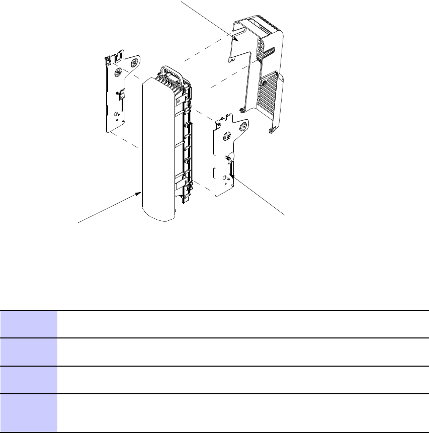
Figure A -3 RF Head Side Mounting Br ack ets and Solar Shield
ti-cdma-04195.eps
RF Head
Solar Shield
2X Side Brackets
Procedure A -3 Procedure to Install Optional RF Filter
1
From Procedure A-2 . If already attached to side mounting brackets, remove
RF Filter mounting bracket.
2
Secure RF Filter to filter mounting bracket using four screws. T orque screws
to 45 in-lbs (5 N-m).
3
Reattach RF Filter mounting bracket to RF Head side mounting brackets and
secure with two captive screws. T orque screws to 45 in-lbs (5 N-m).
4
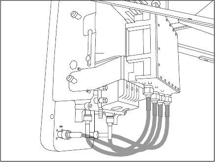
A ttach four RF cables between the antenna and the RF Head.
See Figure A-4 .
Return to Procedure A-2 .step 9
68P09277A59 -8 A -9
MA Y 2007 PRELIMINARY - UNDER DEVELOPMENT
Manual RF Head Installation Procedures Appendix A: Alternate RF Head Installation Procedure
Figure A -4 Antenna to Filter RF Cable Connection Diagr am
ti-cdma-05748.eps
DIV
A -10 68P09277A59 -8
PRELIMINARY - UNDER DEVELOPMENT MA Y 2007

A p p e n d i x
B
Alternate RGPS Installation
68P09277A59 -8 B -1
MA Y 2007 PRELIMINARY - UNDER DEVELOPMENT
RGPS Cabling Installation Appendix B: Alternate RGPS Installation
RGPS Cabling Installation■■■■■■■■■■■■■■■■■■■■■■■■■■■■■■■■■■■■■■■■■■■■■■■■■■■■■■■■■■■■■■
■
■
Objective
This section contains procedures for installing the Remote Global P ositioning System (RGPS).
Cable Description
Cables C and L as listed in T able 3 -1 are required for installation.
Tools Required
The following tools are required for RGPS installation.
•Flat blade screw driver
Cable Pinout
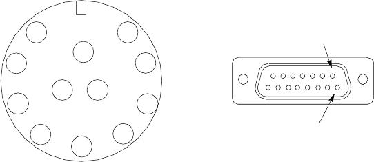
Figure B -1 Connector Pins Numbering for Cables C and L
ti-cdma-04196.eps
1
2
3
4
5
6
7
8
9
10
11 12
CONNECTOR FOR CABLE C
PIN 1
CONNECTOR FOR CABLE C1
PIN 9
B -2 68P09277A59 -8
PRELIMINARY - UNDER DEVELOPMENT MA Y 2007
Access P oint Hardw are Installation RGPS Cabling Installation
Table B -1 Pinout for Cables C and L
Cable C Cable L
Pin No.
Signal Name W ire Color
Connector A
Pin No.
Signal Name
Connector B
Pin No.
9
DC Ground 1 Blue–Black
15 RGPS Return 15
1 P ower 1
Blue
8
RGPS +54V Supply
8
8
DC Ground 2 Y ellow–Black
14 RGPS Return 14
10 P ower 2
Y ellow
7
RGPS +54V Supply
7
4
Transmit P ort (–) Green–Black
9
DA T A (-) From Head
12
5
Transmit P ort (+)
Green 1
DA T A (+) From Head
4
2
Receive P ort (–) White–Black
12
DA T A (-) T o Head
9
3
Receive P ort (+) White
4
DA T A (+) T o Head
1
7
No Connect
Red–Black
No Connect No Connect No Connect
6 No Connect
Red
No Connect No Connect No Connect
12
PPS Timing (–) Brown–Black
10
SYNC (-) From Head
10
11
PPS Timing (+)
Brown
2
SYNC (+) From Head
2
RGPS Installation
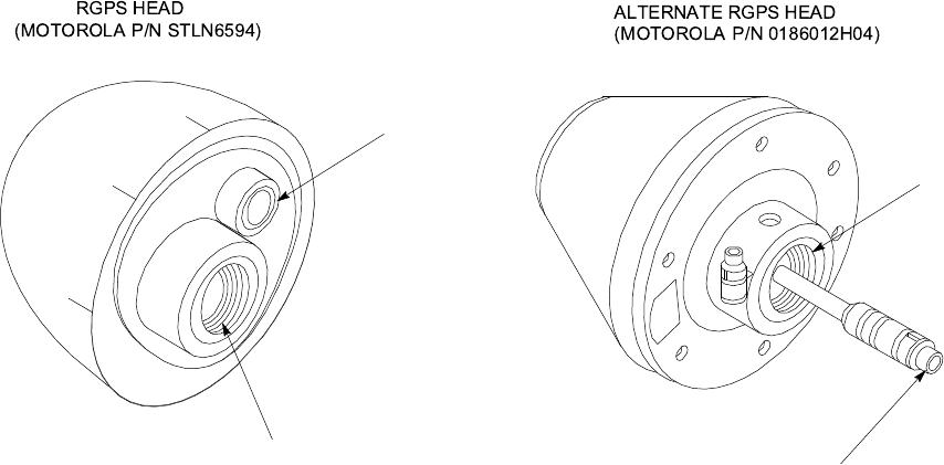
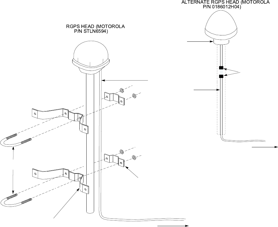
Figure B -2 shows the RGPS Head and Figure B -3 shows the RGPS installation. Be sure to factor
in mounting considerations as described in Chapter 3 Cable Descriptions .
The RGPS head must not mak e contact with an y metal surface other than the pro vided
hardw are. Use only the equipment pro vided to mount the RGPS head. F ailure to do so
could damage the RGPS head.
Procedure B -1 Procedure for Installing the RGPS Head and Cabling
1
Determine the RGPS mounting location.
2
The structure of the w all should be v eried b y a qualied structur al
engineer .
68P09277A59 -8 B -3
MA Y 2007 PRELIMINARY - UNDER DEVELOPMENT

RGPS Cabling Installation Appendix B: Alternate RGPS Installation
Procedure B -1 Procedure for Installing the RGPS Head and Cabling (Continued)
Mounting the RGPS head and hardware to an inadequate wall structure and/or
using inadequate installment methods can result in serious personal injury .
Use the appropriate mounting bolts for the mounting surface and install the
two wall mounting brackets. Refer to Figure B -3 .
3
Route the 12-pin Deutsch connector of the RGPS cable (C) through the RGPS
mounting pipe.
4
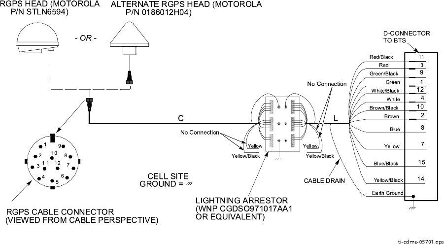
Connect the RGPS cable (C) connector to the RGPS head 12-pin connector
as shown in Figure B -3 and Figure B -4 . Tighten the spinning flange on the
connector a quarter turn to secure the connection.
5
Insert the RGPS mounting pipe into the threaded mount of the RGPS head
and carefully hand-tighten.
6
Install the RGPS mounting pipe into the mounting brackets as shown in
Figure B -3 . Tighten the U -bolt clamps to secure the assembly .
7
Route the free ends of the BTS RGPS cable (L) and RGPS cable (C) to
the lightning arrestor . Remove any excess cable length and strip off
approximately 15 cm of the cables outer insulation.
8
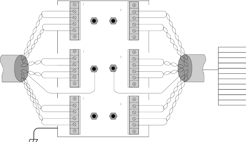
Connect the 12 individual connectors and cable drain of each cable end to the
lightning arrestor as shown in Figure B -5 . Double check the lightning arrestor
connections for compliance with those presented in Figure B -5 .
9
Route the RGPS cable from the lightning arrestor to the bottom of the B CU .
10
If not already open, open the Customer Interface compartment.
If not already done, remove access hole cover .
1 1
Route the RGPS cable up through the access hole and connect to RGPS
D -Connector .
B -4 68P09277A59 -8
PRELIMINARY - UNDER DEVELOPMENT MA Y 2007
Access P oint Hardw are Installation RGPS Cabling Installation
Figure B -2 RGPS Head
ti-cdma-05702.eps
THREADED MOUNT
ADAPTER
THREADED MOUNT
ADAPTER 12-PIN DEUTSCH
TYPE MMP CONNECTOR
12-PIN DEUTSCH
TYPE MMP CONNECTOR
ALTERNATE RGPS HEAD
(MOTOROLA P/N 0186012H04)
RGPS HEAD
(MOTOROLA P/N STLN6594)
68P09277A59 -8 B -5
MA Y 2007 PRELIMINARY - UNDER DEVELOPMENT
RGPS Cabling Installation Appendix B: Alternate RGPS Installation
Figure B -3 Installing the R emote GPS Head
ti-cdma-05740.eps
WALL MOUNTING
BRACKETS (2)
CLAMP BRACKETS (2)
U-BOLTS
CABLE TO LIGHTNING
ARRESTOR (CABLE C)
RGPS HEAD WITH
12 PIN MALE
CONNECTOR
MATING
CONNECTORS
RGPS INTERFACE
CABLE WITH 12 PIN
FEMALE CONNECTOR
ON ONE END AND
UNTERMINATED WIRE
ON OTHER END
CABLE TO LIGHTNING
ARRESTOR (CABLE C)
ALTERNATE RGPS HEAD (MOTOR OLA
P/N 0186012H04)
RGPS H EAD (MOTORO LA
P/N STLN6594)
Connecting the RGPS Cable to Lightning Arrestor
Figure B -4 is a diagram of the RGPS connections. Figure B -5 is a detail of the Lightning
Arrestor connections.
B -6 68P09277A59 -8
PRELIMINARY - UNDER DEVELOPMENT MA Y 2007
Access P oint Hardw are Installation RGPS Cabling Installation
Figure B -4 RGPS to Base Control Unit Connection Diagr am
Blue/Black
Blue
Yellow/Black
Yellow
Green /Black
Green
White/Bla ck
White
Brown/Black
Brown
1
2
3
45
6
7
8
9
10
1 1 12
Earth Groun d
RGPS C ABLE CO NNECTOR
(VIEWED FROM CABLE PE RSPECTIVE)
C L
CABLE DRAIN
LIGHTNING ARRESTOR
(WNP CGDSO971017AA 1
OR E QUIVALENT)
D-CONNECTOR
TO BTS
1
14
10
2
4
12
7
8
15
9
ALTERNATE RGPS HEAD (MOTOR OLA
P/N 0186012H04)
CELL SITE
GRO UND =
Red
Red/Black
3
11
Yellow
Yellow/Black
Yellow
Yellow/Black
No Connection
No Connection
ti-cdma-05701.eps
RGPS H EAD (MOTORO LA
P/N STLN6594)
- OR -
68P09277A59 -8 B -7
MA Y 2007 PRELIMINARY - UNDER DEVELOPMENT
RGPS Cabling Installation Appendix B: Alternate RGPS Installation
Figure B -5 RGPS Lightning Arrestor Wiring
ti-cdma-04190.eps
Blue/Black
Blue
Yellow/Black
Yellow
Green/Black
Green
White/Black
White
Red/Black
Red
Brown/Black
Brown
Cable Drain
Blue/Black
Blue
Yellow/Black
Yellow
Green/Black
Green
White/Black
White
Red/Black
Red
Brown/Black
Brown
Cable Drain
+40VDC Lines +17V DC Lines +17VDC Lines
+17VDC Equipm ent+17VDC Equipment+ 40VDC Equipm ent
L (RGPS)
TO BCU
UNIT
C (RGPS)
TO RGPS
RECEIVER
EARTH GROUND
MOUNTING PLATE
Blue/Black
Blue
Yellow/Black
Yellow
Green/Black
Green
White/Black
White
Red/Black
Red
Brown/Black
Brown
1
2
3
4
5
6
7
8
9
10
11
12
B -8 68P09277A59 -8
PRELIMINARY - UNDER DEVELOPMENT MA Y 2007

A p p e n d i x
C
MMI Cable Fabrication
68P09277A59 -8 C -1
MA Y 2007 PRELIMINARY - UNDER DEVELOPMENT

MMI Cable F abrication Appendix C: MMI Cable F abrication
MMI Cable Fabrication■■■■■■■■■■■■■■■■■■■■■■■■■■■■■■■■■■■■■■■■■■■■■■■■■■■■■■■■■■■■■■
■
■
Purpose
If the Motorola SLN2006A Man Machine Interface (MMI) Interface Kit is not available, cables
can be fabricated by the user to interface a nine -pin serial connector on an Line Maintenance
F acility (LMF) computer platform with an MMI connector . This section provides the information
necessary for fabricating these cables.
Required Parts
Table C -1 P arts R equired to F abricate MMI Cable
Item Part Number
Qty
Description
A
Motorola 3009786R01
1
Ribbon cable assembly , 1.524 M, one 8-contact MMI
connector , one 10-contact connector
B
AMP 749814-1, Belkin
A4B202B GC , or equivalent
1
Receptacle kit, unassembled, 9-position, socket
contacts, unshielded, metal or plastic shell, solder
or crimp-type contacts
Cable Details
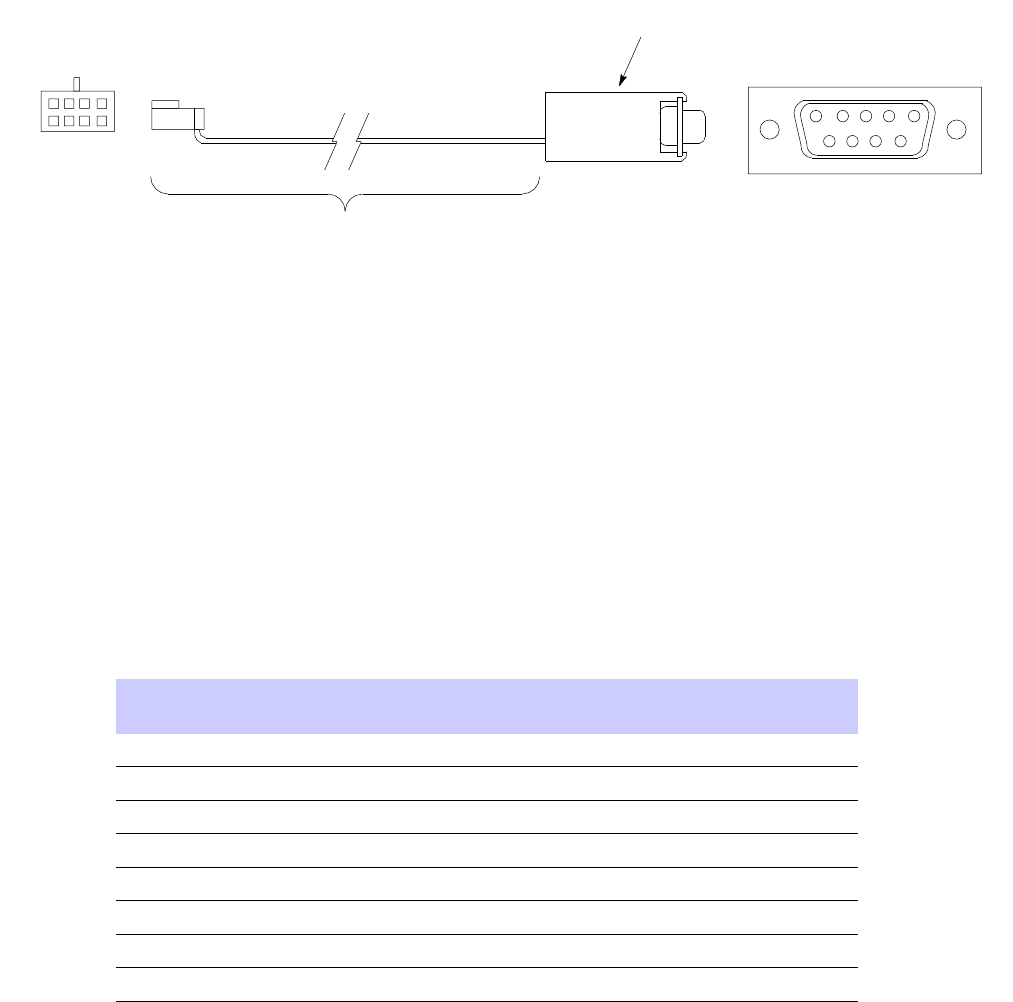
Figure C -1 illustrates the details of the fabricated MMI cable.
C -2 68P09277A59 -8
PRELIMINARY - UNDER DEVELOPMENT MA Y 2007
Access P oint Hardw are Installation MMI Cable F abrication
Figure C -1 F abricated MMI Cable Details
ti-cdma-00133.eps
1 3 5 7
2 4 6 8
8-Contact MMI Plug
Socket Numbering
(Mating Side)
12345
6789
DB-9 Plug
Socket Numbering
(Mating Side)
FABRICATION NOTES:
1. Separate wires at unterminated end of ribbon cable as required to connect to DB-9
connector contacts
2. Dark wire on ribbon cable of cable assembly 3009786R01 connects to pin 1 of the
8-contact plug
3. Strip three ribbon cable wires with connections specified in and connect to
DB-9 plug contacts as specified in Table C-2
4. Shorten un-connected ribbon cable wires enough to prevent contacting DB-9
contacts, leaving enough wire to engage any strain relief in the DB-9 connector shell
Item B
Wire Run List
T able C -2 provides the wire run/pin -out information MMI cable.
Table C -2 F abricated MMI Cable Wire R un List
8-CONT ACT MMI PLUG
CONT ACT
DB-9 PLUG
CONT ACT
1 NC
2 NC
3 NC
Common 4
– — — — — — — — —
5
RxD 5
————————
2
TxD 6
————————
3
7
NC
8 NC
68P09277A59 -8 C -1
MA Y 2007 PRELIMINARY - UNDER DEVELOPMENT
C -2 68P09277A59 -8
PRELIMINARY - UNDER DEVELOPMENT MA Y 2007