Novatel Wireless NRM-EU860D Dual Band Licensed Modular Transmitter User Manual Part 1
Novatel Wireless, Inc. Dual Band Licensed Modular Transmitter Part 1
Contents
- 1. Part 1
- 2. Part 2
- 3. Manual 1
- 4. Manual 2
- 5. Manual 3
- 6. Manual 4
- 7. User Manual 1
- 8. User Manual 2
- 9. User Manual M1210
- 10. User Manual D430
- 11. User Manual D420
- 12. User Manual Corsica
- 13. User Manual Sapporo
- 14. User Manual Vostro 1
- 15. User Manual Vostro 2
- 16. Users Manual Vostro 3
- 17. Users Manual Vostro 4
- 18. User Manual 3
- 19. User Manual 4
- 20. User Manual Gilligan
Part 1

Novatel Wireless Doc No. OM-01017857 Rev 1
PCI Express Mini-card
Integration & Design Guide
Version 2.1

Proprietary & Confidential 2
Novatel Wireless Doc No. OM-01017857 Rev 1
Document Revision History
Rev. ECO # Date Brief Description of Change Originator Approved by
Draft July 21st
2006 Initial release of Draft Version for
Customer Review and Feedback John Whittier
2.0D July 24th
2006 Initial release of Version 2.0 for
Customer Review John Whittier
2.1D Aug 10th
2006 Updates, TRP, design spec’s etc.
Official Release of Version 2.1 John Whittier
2.1 06305 Sept 8th
2006 ECO sign off updates John Whittier
Notice: Restricted Proprietary Information and subject to the confidentiality restrictions contained
in any applicable non-disclosure agreement.
© Copyright Novatel Wireless, Inc. (2006)
The information contained in this document is the exclusive property of Novatel Wireless, Inc. All
rights reserved. Unauthorized reproduction of this manual in any form without the expressed
written approval of Novatel Wireless, Inc. is strictly prohibited. This manual may not, in whole or in
part, be copied, reproduced, translated, or reduced to any electronic or magnetic storage medium
without the written consent of a duly authorized officer of Novatel Wireless, Inc.
The information contained in this document is subject to change without notice and should not be
construed as a commitment by Novatel Wireless, Inc. unless such commitment is expressly given
in a covering document.

Proprietary & Confidential 3
Novatel Wireless Doc No. OM-01017857 Rev 1
Novatel Wireless, Inc. makes no warranties, either expressed or implied, regarding this
document, its merchantability, or its fitness, for any particular purpose.
Legal Disclaimer
This document and the information contained in the PCI Express Mini-card Integration &
Design Guide (together, the “Information”) is provided to you by Novatel Wireless for
informational purposes only.
Novatel Wireless is providing the Information because Novatel Wireless believes the Integration
and Design Guidelines may be useful. The Information is provided on the condition that you will
be responsible for making your own assessments of the information and are advised to verify all
representations, statements and information before using or relying upon any of the Information.
Although Novatel Wireless believes it has exercised reasonable care in providing the Information,
Novatel Wireless does not warrant the accuracy of the Information and is not responsible for any
damages arising from its use or reliance upon the Information. You further understand and agree
that Novatel Wireless in no way represents, and you in no way rely on a belief, that Novatel
Wireless is providing the information in accordance with any standard or service (routine,
customary or otherwise) related to the consulting, services, hardware or software industries.
NOVATEL WIRELESS DOES NOT WARRANT THAT THE INFORMATION IS ERROR-FREE.
NOVATEL WIRELESS IS PROVIDING THE INFORMATION TO YOU "AS IS" AND "WITH ALL
FAULTS." NOVATEL WIRELESS DOES NOT WARRANT, BY VIRTUE OF THIS DOCUMENT,
OR BY ANY COURSE OF PERFORMANCE, COURSE OF DEALING, USAGE OF TRADE OR
ANY COLLATERAL DOCUMENT HEREUNDER OR OTHERWISE, AND HEREBY EXPRESSLY
DISCLAIMS, ANY REPRESENTATION OR WARRANTY OF ANY KIND WITH RESPECT TO
THE INFORMATION, INCLUDING, WITHOUT LIMITATION, ANY REPRESENTATION OR
WARRANTY OF DESIGN, PERFORMANCE, MERCHANTABILITY, FITNESS FOR A
PARTICULAR PURPOSE OR NON-INFRINGEMENT, OR ANY REPRESENTATION OR
WARRANTY THAT THE INFORMATION IS APPLICABLE TO OR INTEROPERABLE WITH ANY
SYSTEM, DATA, HARDWARE OR SOFTWARE OF ANY KIND.
NOVATEL WIRELESS DISCLAIMS AND IN NO EVENT SHALL BE LIABLE FOR ANY LOSSES
OR DAMAGES OF ANY KIND, WHETHER DIRECT, INDIRECT, INCIDENTAL,
CONSEQUENTIAL, PUNITIVE, SPECIAL OR EXEMPLARY, INCLUDING, WITHOUT
LIMITATION, DAMAGES FOR LOSS OF BUSINESS PROFITS, BUSINESS INTERRUPTION,
LOSS OF BUSINESS INFORMATION, LOSS OF GOODWILL, COVER, TORTIOUS CONDUCT
OR OTHER PECUNIARY LOSS, ARISING OUT OF OR IN ANY WAY RELATED TO THE
PROVISION, NON-PROVISION, USE OR NON-USE OF THE INFORMATION, EVEN IF YOU
HAVE BEEN ADVISED OF THE POSSIBILITY OF SUCH LOSSES OR DAMAGES.

Proprietary & Confidential 4
Novatel Wireless Doc No. OM-01017857 Rev 1
Table of Contents
Reference Documents................................................................................................................... 8
PCI Express Mini Card References ................................................................................ 8
3GPP References ........................................................................................................... 8
Notices.......................................................................................................................................... 10
Safety Warning.............................................................................................................. 10
Federal Communications Commission Notice (FCC—United States).......................... 11
Radio Frequency Exposure Evaluation Requirements ................................................. 11
Compliance & Certification Requirements .................................................................... 13
Windows Platforms........................................................................................................ 14
Technical Support Contacts .......................................................................................... 14
Getting Started............................................................................................................................. 15
General.......................................................................................................................... 15
Setting Up......................................................................................................................15
Hardware Development Kit (HDK).............................................................................................. 21
HDK............................................................................................................................... 21
Photo of Top View......................................................................................................... 26
Schematic...................................................................................................................... 27
MobiLink Phoenix SDK ............................................................................................................... 28
SDK ............................................................................................................................... 28
SDK MODULES ............................................................................................................ 28
PHOENIX SERVER Software design ........................................................................... 30
Product Overview........................................................................................................................ 32
HSDPA Module Overview ............................................................................................. 32
EVDO Module Overview.......................................................................................... 34
Network Overview..................................................................................................... 35
Application Software Overview ..................................................................................... 36
Device Specifications.................................................................................................................. 37
PCI Express Mini Card.................................................................................................. 37
Hardware....................................................................................................................... 38
Interface Specification................................................................................................... 44
Firmware........................................................................................................................56
Environmental ............................................................................................................... 64
Reliability ....................................................................................................................... 65
Packaging...................................................................................................................... 65
Labeling......................................................................................................................... 65
RoHS............................................................................................................................. 65
WEEE............................................................................................................................65
Integrator Design Elements: Antenna, SIM & SMBus............................................................. 66
Antenna .........................................................................................................................66
SIM Design Guidelines.................................................................................................. 70
SM Bus Design Guidelines............................................................................................ 77
MobiLink Connection Manager .................................................................................................. 79
GENERAL FEATURES................................................................................................. 79
MOBILINK™ FEATURES ............................................................................................. 83
Appendix A - Customer Configuration & ID’s......................................................................... 108
Introduction.................................................................................................................. 108
USB ID......................................................................................................................... 108
HW ID.......................................................................................................................... 108
IMEI Numbers (HSDPA).............................................................................................. 108
HSDPA Product Release Instruction (PRI) ................................................................. 109
E725 Provisioning with IOTA ...................................................................................... 124
Appendix B - Development Tools & Procedures.................................................................... 126

Proprietary & Confidential 5
Novatel Wireless Doc No. OM-01017857 Rev 1
Appendix C - Regulatory Approval and Compliance............................................................. 130
FCC (Federal Communication Commission) .............................................................. 130
CE (Conformance European)...................................................................................... 131
GCF (Global Certification Forum) ............................................................................... 133
PTCRB (PCS Type Certification Review Board)......................................................... 134
Appendix D - Carrier Accreditation and Infrastructure IOT .................................................. 135
Carrier Accreditation.................................................................................................... 135
Infrastructure IOT ........................................................................................................ 135
Estimated Timelines for Compliance & Certification............................................................. 136
EV-DO FCC Accreditation........................................................................................... 136
EV-DO CDG Interoperability ....................................................................................... 136
EV-DO Verizon Certification Process.......................................................................... 137
HDSPA FCC Accreditation.......................................................................................... 137
GCF Compliance Process........................................................................................... 138
PTCRB Compliance Process ...................................................................................... 139
CE Mark Certification Process .................................................................................... 140
Infrastructure IOT Process .......................................................................................... 141
Carrier Accreditation Process ..................................................................................... 142
Appendix E - Reference Parts Specifications......................................................................... 144
Appendix G - Phoenix API Interface to PCI Express Mini Card............................................ 146
Client Object................................................................................................................ 146
IEventPhoenixNotifySink object .................................................................................. 169
QoS object................................................................................................................... 170
Blaze object................................................................................................................. 174
Hotspots object............................................................................................................ 176
Menu object................................................................................................................. 177
Language object.......................................................................................................... 179
ProfileManager object ................................................................................................. 180
Profile object................................................................................................................ 183
NetMonkey Lib objects................................................................................................ 195
LAN object................................................................................................................... 195
WLAN object ............................................................................................................... 200
WWAN object.............................................................................................................. 208
Appendix H - AT Commands.................................................................................................... 215
Novatel Wireless AT Command Set............................................................................ 215
Appendix I - Novatel Wireless Developer Network Library................................................... 229
Appendix J - Additional AT Commands.................................................................................. 239
Miscellaneous AT Commands for EU860D/EU870D.................................................. 263
CME ERROR Codes for CDMA Commands............................................................... 265
CMS Error Codes for CDMA Commands.................................................................... 267
Appendix K - Data sheets ......................................................................................................... 268
EU860D....................................................................................................................... 268
EU870D....................................................................................................................... 268
E725 ............................................................................................................................ 268
Appendix L - FAQ (Frequently Asked Questions).................................................................. 269
Appendix M - Glossary.............................................................................................................. 270

Proprietary & Confidential 6
Novatel Wireless Doc No. OM-01017857 Rev 1
Table of Figures
Figure 1: Applications.......................................................................................................... 28
Figure 2: Module Design..................................................................................................... 30
Figure 3: Automation Server ............................................................................................... 30
Figure 4: State Machine...................................................................................................... 31
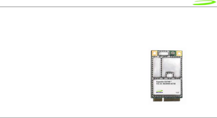
Figure 5: E725 Module........................................................................................................ 40
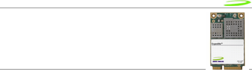
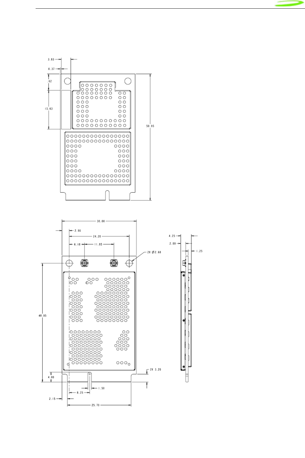
Figure 6: EU860D/EU870D Module.................................................................................... 41
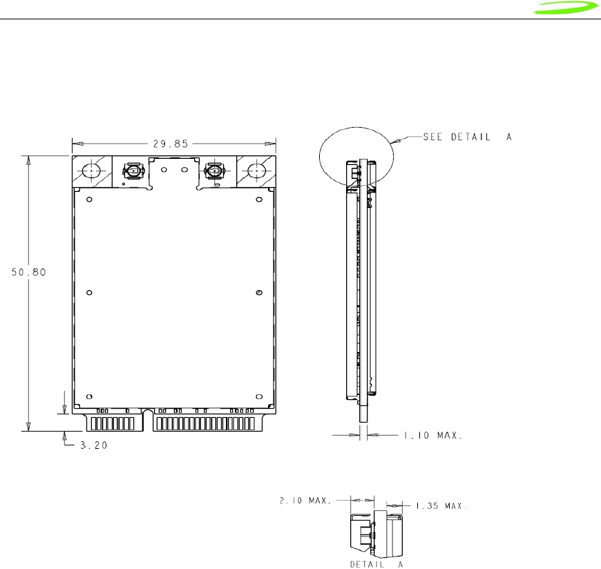
Figure 7: EU860D/EU870D Module.................................................................................... 42
Figure 8: PCIe Minicard Module Envelope ......................................................................... 43
Figure 9: W_Disable Pull-up Configuration......................................................................... 45
Figure 10: Total Radiated Power .......................................................................................... 68
Figure 11: Plug-in SIM (shown from contact side)................................................................ 70
Figure 12: IO driver and pull-ups........................................................................................... 72
Figure 13: Reference circuit.................................................................................................. 73
Figure 14: SM Pull-up Configuration..................................................................................... 78
Figure 15: Main MobiLink Display......................................................................................... 80
Figure 16: Skin Design.......................................................................................................... 81
Figure 17: On-Line Help........................................................................................................ 82
Figure 18: Status Indication .................................................................................................. 83
Figure 19: 3G Wireless View................................................................................................. 84
Figure 20: WiFi View ............................................................................................................. 85
Figure 21: HotSpot Activation ............................................................................................... 86
Figure 22: Network Connection............................................................................................. 86
Figure 23: Ethernet View....................................................................................................... 87
Figure 24: Connection Button ............................................................................................... 88
Figure 25: 3G Profiles ........................................................................................................... 89
Figure 26: Profile Settings..................................................................................................... 90
Figure 27: Different Tab Settngs........................................................................................... 90
Figure 28: Profile Wizard Step 1 ........................................................................................... 91
Figure 29: Profile Wizard Step #2 ......................................................................................... 92
Figure 30: Profile Wizard Step #3 ......................................................................................... 92
Figure 31: General Tab ......................................................................................................... 93
Figure 32: Mobile Tab ........................................................................................................... 94
Figure 33: WiFi Tab............................................................................................................... 95
Figure 34: WAP Window....................................................................................................... 95
Figure 35: Ethernet Tab ........................................................................................................ 96
Figure 36: AP Window .......................................................................................................... 96
Figure 37: CDMA................................................................................................................... 97
Figure 38: UMTS/HSDPA ..................................................................................................... 97
Figure 39: Report Log ........................................................................................................... 98
Figure 40: Desktop Transparency......................................................................................... 99
Figure 41: About Dialogue .................................................................................................. 100
Figure 42: Enter PUK .......................................................................................................... 100
Figure 43: Configuration Menu............................................................................................ 100
Figure 44: Quick Access Button Default Functions............................................................. 101
Figure 45: MobiLink SMS Client.......................................................................................... 102
Figure 46: Compose Message............................................................................................ 104
Figure 47: Address Book..................................................................................................... 106
Figure 48: Select Group Contacts....................................................................................... 107
Figure 49: RF Connector..................................................................................................... 144
Figure 50: Mini PCI Express Connector.............................................................................. 145

Proprietary & Confidential 7
Novatel Wireless Doc No. OM-01017857 Rev 1
Table of Tables
Host Interface specification ........................................................................................................... 44
Idle/Low Power Mode Current....................................................................................................... 49
Peak Current.................................................................................................................................. 49
Transmit Power Consumption ....................................................................................................... 50
EU860D/870D & E725 Environmental Specification..................................................................... 64
Design specifications for the Diversity EVDO antenna ................................................................. 66
CDMA Test Frequencies ............................................................................................................... 69
GSM-1900 Test Frequencies ........................................................................................................ 69
Table 1: SIM interface signals ....................................................................................................... 71
Table 2: VCC electrical requirements............................................................................................71
Table 3: RST electrical requirements ............................................................................................71
Table 4: CLK electrical requirements ............................................................................................72
Table 5: IO electrical requirements................................................................................................ 72
Status Indication ............................................................................................................................ 83
3G Indicators ................................................................................................................................. 87
Menu Subjects............................................................................................................................... 88
General Tab Features ................................................................................................................... 93
Mobile Tab Features...................................................................................................................... 94
Identity Properties.......................................................................................................................... 97
Report Values................................................................................................................................ 98
Mailbox List.................................................................................................................................. 102
Fields List..................................................................................................................................... 103
Tool Bar Button............................................................................................................................ 104
Destination Addresses................................................................................................................. 105
Address Books............................................................................................................................. 106
R&TTE......................................................................................................................................... 131
GSM/GPRS European Regulations............................................................................................. 132
CME Error Codes ........................................................................................................................ 265
CMS Error Codes ........................................................................................................................ 267

Proprietary & Confidential 8
Novatel Wireless Doc No. OM-01017857 Rev 1
Reference Documents
PCI Express Mini Card References
PCI Express Mini Card Electromehcanical Specification Revision 1.0 June 2, 2003
PCI Express Card Electromechancil Specification revision 1.1 March 28th 2005
SMBus Specification, Revision 2.0
The I2C-BUS SPECIFICATION Version 2.1 January 2000
3GPP References
The following documents contain provisions which, through reference in this text, constitute
provisions of the present document.
References are either specific (identified by date of publication, edition number, version
number, etc.) or non-specific.
For a specific reference, subsequent revisions do not apply.
For a non-specific reference, the latest version applies. In the case of a reference to a 3GPP
document (including a GSM document), a non-specific reference implicitly refers to the
latest version of that document in the same Release as the present document.
[1] Void.
[2] 3GPP TS 23.038: "Alphabets and language-specific information".
[3] 3GPP TS 23.040: "Technical realization of the Short Message Service (SMS) ".
[4] 3GPP TS 23.041: "Technical realization of the Cell Broadcast Service (CBS)".
[5] 3GPP TS 24.008: "Mobile Radio Interface Layer 3 specification; Core Network
Protocols; Stage 3".
[6] 3GPP TS 24.011: "Short Message Service (SMS) support on mobile radio interface".
[7] 3GPP TS 24.012: "Cell Broadcast Service (CBS) support on the mobile radio
interface".
[8] 3GPP TS 27.001: "General on Terminal Adaptation Functions (TAF) for Mobile
Stations (MS)".
[9] 3GPP TS 27.007: "AT command set for User Equipment (UE)".
[10] 3GPP TS 51.011: "Specification of the Subscriber Identity Module - Mobile
Equipment (SIM - ME) interface".
[11] ITU-T Recommendation V.25ter: "Serial asynchronous automatic dialing and
control".
[12] ITU-T Recommendation V.24: "List of definitions for interchange circuits between
data terminal equipment (DTE) and data circuit-terminating equipment (DCE)".
[13] ITU-T Recommendation E.164: "The international public telecommunication
numbering plan".

Proprietary & Confidential 9
Novatel Wireless Doc No. OM-01017857 Rev 1
[14] ITU-T Recommendation E.163: "Numbering plan for the international telephone
service".
[15] 3GPP TR 21.905: "Vocabulary for 3GPP Specifications".
[16] 3GPP TS 31.102: "Characteristics of the USIM application.

Proprietary & Confidential 10
Novatel Wireless Doc No. OM-01017857 Rev 1
Notices
Safety Warning
Neither the E725 nor EU860D / EU870D products may be used in an environment where radio
frequency equipment is prohibited or restricted in its use. This includes aircraft/airports, hospitals,
and other sensitive electronic areas.
Do not operate RF devices in an environment that may be susceptible to radio interference
resulting in danger, specifically:
• Areas where prohibited by the law
Follow any special rules and regulations and obey all signs and notices. Always
turn off the host device when instructed to do so, or when you suspect that it may
cause interference or danger.
• Where explosive atmospheres may be present
Do not operate your modem in any area where a potentially explosive
atmosphere may exist. Sparks in such areas could cause an explosion or fire
resulting in bodily injury or even death. Be aware and comply with all signs and
instructions.
• Users are advised not to operate the modem while at a refueling point or service
station.
Users are reminded to observe restrictions on the use of radio equipment in fuel
depots (fuel storage and distribution areas), chemical plants or where blasting
operations are in progress.
• Areas with a potentially explosive atmosphere are often but not always clearly
marked.
Potential locations can include gas stations, below deck on boats, chemical
transfer or storage facilities, vehicles using liquefied petroleum gas (such as
propane or butane), areas where the air contains chemicals or particles, such as
grain, dust or metal powders, and any other area where you would normally be
advised to turn off your vehicle engine.
• Near Medical and life support equipment
Do not operate your modem in any area where medical equipment, or life support
equipment may be located, or near any equipment that may be susceptible to
any form of radio interference. In such areas, the host communications device
must be turned off. The modem may transmit signals that could interfere with this
equipment.
• On an aircraft, either on the ground or airborne
In addition to FAA requirements, many airline regulations state that you must
suspend wireless operations before boarding an airplane. Please ensure that the
host device is turned off and your modem is removed from the card slot prior to
boarding aircraft in order to comply with these regulations. The modem can
transmit signals that could interfere with various onboard systems and controls.
• While operating a vehicle
The driver or operator of any vehicle should not operate a wireless data device.
Doing so will detract from the driver or operator's control and operation of that

Proprietary & Confidential 11
Novatel Wireless Doc No. OM-01017857 Rev 1
vehicle. In some countries, operating such communication devices while in
control of a vehicle is an offence.
Under extended operation the EU870D and EU860D modem will generate a noticeable amount of
heat. Like all PC Cards, the modem generates heat during normal operation and will be heated
by the host computer. For this reason it is recommended that after extended periods of operation,
prior to removal and handling, you allow the modem to cool down.
Federal Communications Commission Notice (FCC—United States)
FCC applies to E725 and EU860D/870D. Refer to sections on Regulatory Compliance for more
details.
Electronic devices, including computers and wireless modems, generate RF energy incidental to
their intended function and are therefore subject to FCC rules and regulations. This equipment
will be tested, and found to be within the acceptable limits for a Class B digital device, pursuant to
part 15 of the FCC Rules. These limits are designed to provide reasonable protection against
harmful interference when the equipment is operated in a residential environment. This
equipment generates radio frequency energy and is designed for use in accordance with the
manufacturer’s user manual. However, there is no guarantee that interference will not occur in
any particular installation. If this equipment causes harmful interference to radio or television
reception, which can be determined by turning the equipment off and on, you are encouraged to
try to correct the interference by one or more of the following measures:
• Reorient or relocate the receiving antenna
• Increase the separation between the equipment and the receiver
• Connect the equipment into an outlet on a circuit different from that to which the receiver
is connected
• Consult the dealer or an experienced radio/television technician for help
This device complies with Part 15 of the Federal Communications Commission (FCC) Rules.
Operation is subject to the following two conditions:
1. This device may not cause harmful interference.
2. This device must accept any interference received, including interference that may
cause undesired operation.
Radio Frequency Exposure Evaluation Requirements
This wireless module is a radio transmitter and receiver. It is designed and manufactured not to
exceed the exposure limits for radio frequency (RF) energy set by the Federal Communications
Commission (FCC) of the U.S. Government. These limits are part of comprehensive guidelines
and establish permitted levels of RF energy for the general population. The guidelines are based
on standards that were developed by independent scientific organizations through periodic and
thorough evaluation of scientific studies. The standards include a substantial safety margin
designed to assure the safety of all persons, regardless of age and health.
The exposure standard for wireless devices including mobile phones and wireless modems uses
a unit of measurement known as the Specific Absorption Rate, or SAR. Tests for SAR are
conducted using standard operating positions reviewed by the FCC with the device under test

Proprietary & Confidential 12
Novatel Wireless Doc No. OM-01017857 Rev 1
transmitting at its highest certified power level in all frequency bands. Although the SAR is
determined at the highest certified power level, the actual SAR level of the phone or modem while
operating can be well below the maximum value. This is because the phone or modem is
designed to operate at multiple power levels so as to use only the power required to reach the
network. In general, the closer you are to a wireless base station antenna, the lower the power
output.
Before this device is made available for sale to the public, it must be tested and certified to the
FCC that it does not exceed the limit established by the government-adopted requirement for safe
exposure. The tests are performed in positions and locations (for example, at the ear or worn on
the body) as required by the FCC for each model.
In general, for the United States market, the embedded modules are treated as “mobile devices”
as per FCC CFR47 paragraph 2.1091. A mobile device is defined as “a transmitting device
designed to be used in other than fixed locations and to generally be used in such a way that a
separation distance of at least 20 cm is normally maintained between the transmitter’s radiating
structure(s) and the body of the user or nearby persons.” Manufactures of mobile devices may
be able to submit a Maximum Exposure Rate (MPE) calculation in order to demonstrate SAR
compliance.
CE (Conformité Européenne or European Conformity)
This module will be tested to and conforms to the regulatory requirements of the European Union
and has attained CE Marking. The CE Mark is a conformity marking consisting of the letters "CE".
The CE Mark applies to products regulated by certain European health, safety and environmental
protection legislation. The CE Mark is obligatory for products it applies to: the manufacturer
affixes the marking in order to be allowed to sell his product in the European market.
Radiocommunications and Telecommunications Terminal Equipment Industries (R&TTE)
This is mandatory for European operation and the directive applies to products using the radio
frequency spectrum and all equipment attached to public telecommunications networks.
This product conforms to the essential requirements of the Radiocommunications and
Telecommunications Terminal Equipment Directive (R&TTE) 1999/5/EC with respect to the
following articles:
• 3.1a Safety
• 3.1b EMC
• 3.2 Spectrum
A notified body will determine that this device has properly demonstrated that the requirements of
the directive have been met and has issued a favorable certificate of expert opinion. As such the
device will bear the notified body number (TBD) after the CE Mark.

Proprietary & Confidential 13
Novatel Wireless Doc No. OM-01017857 Rev 1
Compliance & Certification Requirements
PCS Type Certification Review Board (PTCRB)
PTCRB Certification is mandated and the product is technically evaluated to meet the minimum
requirements for registration on the PTCRB Operators’ networks. The purpose of the PTCRB is to
provide the framework within which GSM Mobile Equipment (ME) Type Certification can take
place for members of the PTCRB. The PTCRB process is recommended for all Manufacturers
who wish to have their products operating within the areas served by the PTCRB Operators. This
includes but is not limited to determination of the test specifications and methods to implement
the Type Certification process for GSM Mobile Equipment.
PTCRB type certification will be based on GSM and OMA (Open Mobile Alliance) Specifications
with modifications per North American Standards and additional requirements from FCC rules,
and any other government agency that may have jurisdiction and or competence in the matter.
Additions to the PTCRB Specifications will be developed by the GSM operators. The additions
will be limited to MS-related features. The PTCRB document NAPRD 03 (Permanent Reference
Document) will be modified to include references to the above specifications once they are written
and accepted by majority of the review board.
To learn more about device certifications, please visit the PTCRB Website. You must sign up as
a member to gain access
Global Certification Forum (GCF),
The Global Certification Forum (GCF) is an independent organization with a wide-ranging
membership of operators, equipment manufacturers and other interested parties. The actions of
the Forum are actively supported by key staff from the Association Technical Projects operation
and by the Association Executive Management Committee.
GCF is recommended but not mandatory for attachment to the European network. It is a
partnership between network operators and terminal manufacturers and allows independent
interoperability validation of the 2G and 3G mobile wireless terminal. GCF is typically required for
formal carrier technical acceptance of the mobile wireless terminal.
Membership of GCF is entirely voluntary. Full GCF membership is open to mobile terminal
manufacturers and network operators. Other interested members of the mobile wireless
community, including test laboratories and test equipment manufacturers, may participate in GCF
as observers.
The current membership includes almost 150 network operators worldwide, more than 35 leading
terminal manufacturers and over 50 test equipment manufactures. Members decide the
organization and administration of the forum at regular Steering Group meetings. Technical
issues associated with testing new terminals and features are reviewed at regular Agreement
Group meetings by manufacturers, test laboratories and other observers.
To learn more about device certifications, please visit the GCF Website. The website identifies
manufacture, terminal names and the date which the terminal was certified. You must sign up as
a member to gain full access.

Proprietary & Confidential 14
Novatel Wireless Doc No. OM-01017857 Rev 1
Windows Platforms
The Phoenix API will interface with your top level applications and provide the abstraction of the
module specifics to the upper applications. Please refer to the Phoenix API Interface Appendix for
details.
Please refer to the MobiLink Phoenix SDK chapter for details on developing applications and
communicating with the modem on Windows platforms.
Technical Support Contacts
WWW: http://www.nvtl.com/support/index.html
Email: support@novatelwireless.com

Proprietary & Confidential 15
Novatel Wireless Doc No. OM-01017857 Rev 1
Getting Started
General
The purpose of this document is to provide advance design and integration information to assist
in the integration planning and evaluation of Novatel Wireless PCI Express Mini-cards. This
document is intended to specify key components of the integration tools available for the Novatel
Wireless line of PCI Express Mini-cards.
The E725, EU860D & EU870D are Novatel Wireless’ versatile modules that add WWAN
capability to other devices. They were developed to be integrated into other devices based on the
PCI Express Mini-card specification 1.0.
The E725, EU860D and EU870D will work with all Windows driven laptops given the drivers are
properly installed. When MobiLink™ is installed on a Windows OS system it will automatically
include the drivers necessary to communicate with the PCI Express Mini-card. MobiLink™ is
Novatel’s Windows application manager for the PCI Express Mini Card. MobiLink provides an
easy interface to make a data connection, change operating parameters, and view alerts such as
SMS or signal strength indicator. However, anyone can still install the drivers manually. In
addition, once the drivers are installed, following the Phoenix Client API functions, anyone could
develop their Client side software manager to interact with the PCI Express Mini-card.
When using any of these devices, EU860D, EU870D or the E725, activation is required for the
device to be allowed on the operator’s network. For example, Sprint requires the customer to run
IOTA (Internet Over-The-Air) provisioning to prepare the device to work on the wireless network.
Please refer to the Customer Configuration section on provisioning with IOTA for assistance.
The EU860D and EU870D require a valid SIM card before it can be used on the operator’s
wireless network. Please refer to the Customer Configuration section on PRI for further
information.
Setting Up
The purpose of this section is to assist in the initial connection and provide the reader with
instructions for how to setup and establish communication with the Novatel Wireless line of PCI
Express Mini-card. The following setup guide refers to an HSDPA Mini-card for convenience of
the set up discussion. The same setup is valid for both the HSDPA and EVDO Mini-cards.
Setting up and establishing communication with the Novatel Wireless PCI Express Mini-card
involves:
o Connecting the PCI Express Mini-card to the computer and the Development Board.
o Establishing communication with the PCI Express Mini-card and determining the
computer COM Port being used.
o Setting up and using the HyperTerminal program to communicate with the Mini-card
CONNECTING THE PCI EXPRESS MINI-CARD TO THE COMPUTER AND THE
DEVELOPMENT BOARD
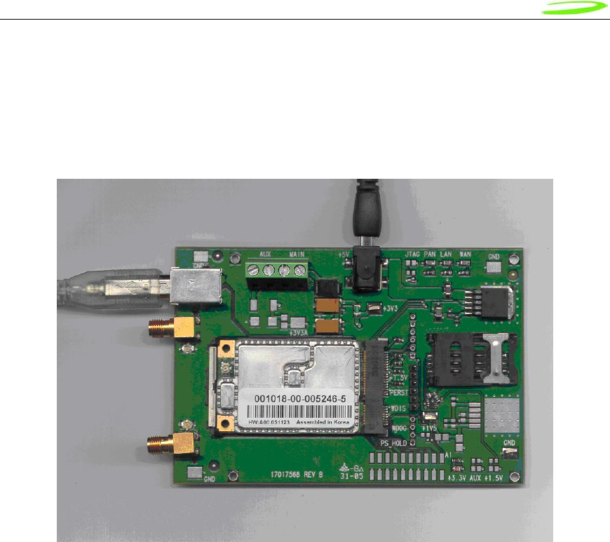
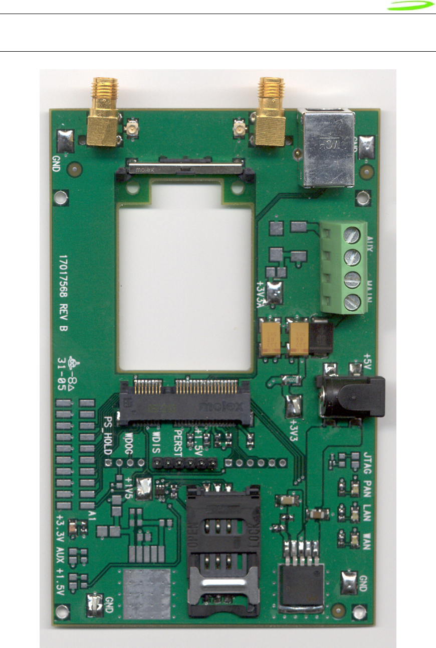
Insert the PCI Express Mini-card into the Development Board (Novatel Wireless Part # 01017568)
by sliding the connector end of the Mini-card into the Molex connector. Push down on the
opposite end of the Mini-card until the 2 black locking tabs snap into place.
Proprietary & Confidential 16
Novatel Wireless Doc No. OM-01017857 Rev 1
Connect an A to B USB cable from the Development Board to the computer USB port.
When ready to power up the modem, plug the AC wall adaptor that came with the Development
board into the wall.
If desired, the Development Board can be powered by a bench top power supply. See the
Hardware Development Kit section for more details.
Figure 1 – Modem Interface Board and Cables
ESTABLISHING COMMUNICATION WITH THE PCI EXPRESS MINI-CARD AND
DETERMINING THE COMPUTER COM PORT BEING USED
Once the modem is powered up and connected, you should hear a sound indicating the computer
has recognized the modem.
Determining the Computer’s Active Primary COM Port
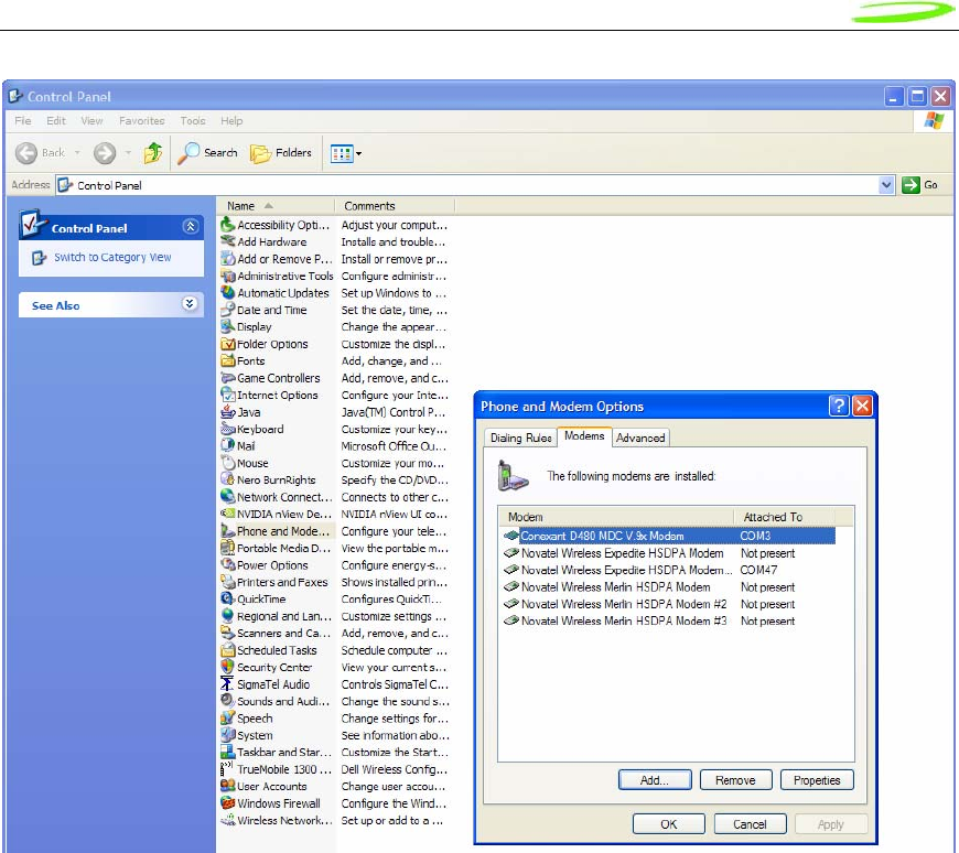
To verify the computer’s recognition of the modem and to verify which Primary COM Port it is
connected to, navigate to Start\Control Panel\Phone and Modem Options and then click on the
Modems tab within the Phone and Modem Options window. Refer to Figure 2 below.
Proprietary & Confidential 17
Novatel Wireless Doc No. OM-01017857 Rev 1
Figure 2 – Phone and Modems Options Window
Look for the Novatel Wireless Merlin HSDPA Modem item on the list. To the right of this item in
the ‘Attached To’ column, you will see a COM port number - make a note of this Primary COM
Port Number. If you do not see any COM No. for this item and you only see “Not Present”, then
this indicates that the modem is not being recognized and is not attached to a COM Port on the
computer. In this case, make sure the USB and power cable are properly connected at both
ends. If the modem has properly booted up, with no SIM in the SIM holder, the WAN LED on the
Development Board should be blinking at a steady rate. If there is a SIM in the SIM Holder, the
LED will be solid green.
Determining the Computer’s Active Secondary or Status COM Port
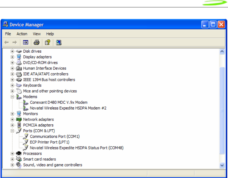
To verify which Secondary, or Status COM Port the modem is connected to, navigate to
Start\Control Panel\System. After you have double-clicked on the System Icon, click on the
Hardware Tab within the System Properties window. Now click on the Device Manager tab. In
the Device Manager window, click on the “+” beside Modems to expand this item. You should
now see the Novatel Wireless Expedite HSDPA Modem, or something similar listed here. Refer
to Figure 3 below. Now click on the “+” beside Ports (COM & LPT) to expand this item. You
should now see the Novatel Wireless Expedite HSDPA Status Port (COM XX) listed here. This is
the Secondary or Status COM port Number. Again, refer to Figure 3 below. Make a note of this
Port Number.
Proprietary & Confidential 18
Novatel Wireless Doc No. OM-01017857 Rev 1
Figure 3 – Device Manager Window Showing the Computer’s Active Status COM Port
SETTING UP HYPERTERMINAL TO COMMUNICATE WITH THE MODEM
Ensure that the Mini-card is still powered on with a USB connection to the computer, and that it is
recognized by the computer as per the previous step.
Open up a HyperTerminal session by navigating to
Start\All Programs\Accessories\Communications\HyperTerminal.
Proprietary & Confidential 19
Novatel Wireless Doc No. OM-01017857 Rev 1
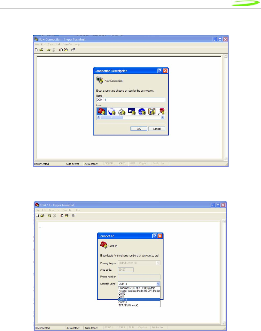
Type in a Connection Description title, such as the Active Primary COM Port number that was
identified earlier - click ‘OK’. See Figure 4 below as an example:
Figure 4 – HyperTerminal Connection Description Window
In the “Connect Using” pull down menu, select the proper COM port (Primary COM port number),
that the computer is using to communicate with the modem, then click ‘OK’. See the example in
Figure 5 below:
Figure 5 – HyperTerminal COM Port Selection Window
Proprietary & Confidential 20
Novatel Wireless Doc No. OM-01017857 Rev 1
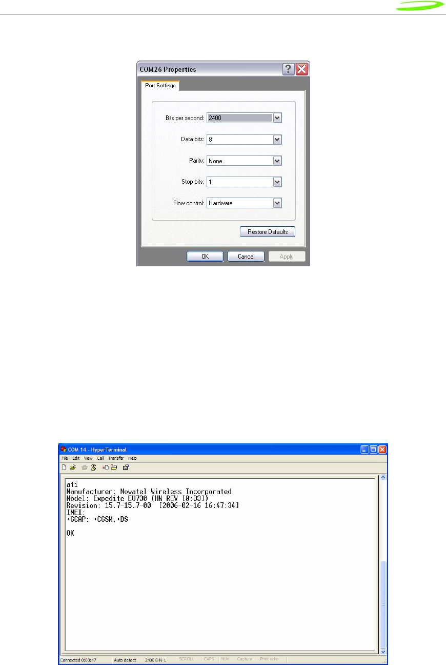
When the ‘COM XX Properties’ window comes up, just click on OK as there is no need to select
or modify any of these settings. Refer to Figure 6 below:
Figure 6 – HyperTerminal Properties Window
Now the modem should be automatically connected, as will be indicated in the bottom left corner
of the HyperTerminal window. To further ensure there is communication to the modem, type
“ATI” and press ENTER. The modem manufacturer, model number, FW revision and IMEI
information will then be returned as is shown in Figure 7 below.
If no information is returned in the HyperTerminal window after typing ATI, then click on the
Disconnect tab at the top of the HyperTerminal window (or click on Call\Disconnect). Reconnect
by clicking on the Connect tab at the top of the HyperTerminal window (or click on Call\Connect).
Now type ATE which will enable the “echo” function of the modem and therefore will allow the
characters typed in the HyperTerminal window to be displayed. Once this has been done, retype
the ATI command and all the modem information should now be displayed in the HyperTerminal
window.
Figure 7 – HyperTerminal Communication Window
Proprietary & Confidential 21
Novatel Wireless Doc No. OM-01017857 Rev 1
Hardware Development Kit (HDK)
HDK
The Hardware Development Kit (HDK) consists of a development board, power supply and USB
connection. The interface board communicates to the host PC via a USB cable. It is powered via
an external wall mount power pack or direct contacts to a lab power supply may be used. The
development board provides a SIM holder and indicator LED’s. The indicator LED’s align to the
WPAN, WLAN and WWAN LED as specified in the PCI Express Mini Card Electromechanically
Specification.
Use
The board is intended to be used in a lab or office environment. It supports the HSDPA and
EVDO minicard development.
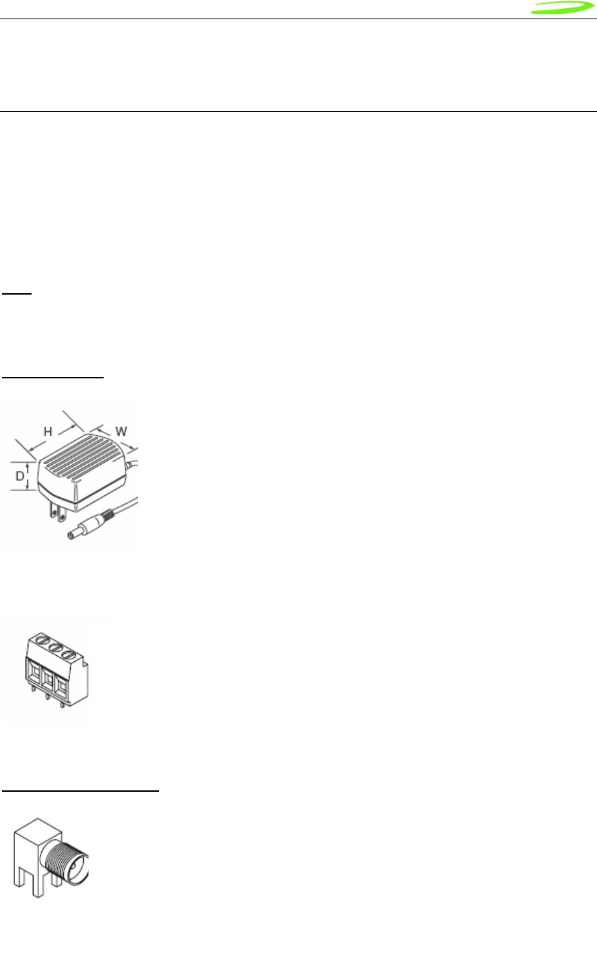
Power Supply
Antenna Connections
For lab use, the development board can be directly wired to external
programmable power supplies giving individual control of the +3.3V and
+3.3VAUX rails. The power connections are made via screw terminal blocks, as
shown at left. Polarity protection is provided by series diodes. To account for the
diode voltage drop, the input voltage must be around 4.0VDC to get 3.3VDC to
the power rails.
To provide a more robust means of connecting antennas to the minicards, the
development board has 2 SMA jacks mounted on the rear edge of the board. A
short length of coax cable runs from each SMA connector to the UFL
connectors on the minicard.
For lab use, an AC adaptor is used. This is a wall mount power adaptor
with a rated output of 5VDC. The 5VDC ± 5% at 3.0 A max power
supply is connected to an LDO regulator on the HDK which outputs
+3.3V to the +3.3V rail. Since neither the HSDPA nor EVDO modules
use the +3.3VAUX supply, this rail is not powered.
The DC plug on the wall mount adaptor will fit into the DC input jack on
the development board.

Proprietary & Confidential 22
Novatel Wireless Doc No. OM-01017857 Rev 1
Audio
The development board has a provision for testing the audio functions of the minicard. The pin
header will consist of 6 signals, comprised of the 4 PCM signals, power and ground. Access is
provided via non-populated connector (P3 on the Assembly drawing) and is indicated on the
schematic as PCM.
LEDs
There is a total of 7 surface mount LEDs are available of which 4 are populated. Their functions
are as follows:
The indicator LED’s align to the WPAN, WLAN and WWAN LED as specified in the PCI Express
Mini Card Electromechanically Specification.
Signal Reference
PCM_CLK P3-Pin 1
PCM_SYNC P3-Pin 2
PCM_DOUT P3-Pin 3
PCM_DIN P3-Pin 4
GND P3-Pin 5
+3.3V P3-Pin 6
Reference Function Colour Comment
D1 PAN Green Populated
D2 LAN Green Populated
D3 WAN Green Populated
D5 +3.3V Red Populated
D6 +3.3VAUX Red Not Populated
D7 +1.5V Red Not Populated
D9 JTAG Green Not Populated
Note that not all minicards will have PCM connections brought out to
the minicard header as it is a population option. Thisis not presently
poplated for all commercial minicards.
Proprietary & Confidential 23
Novatel Wireless Doc No. OM-01017857 Rev 1
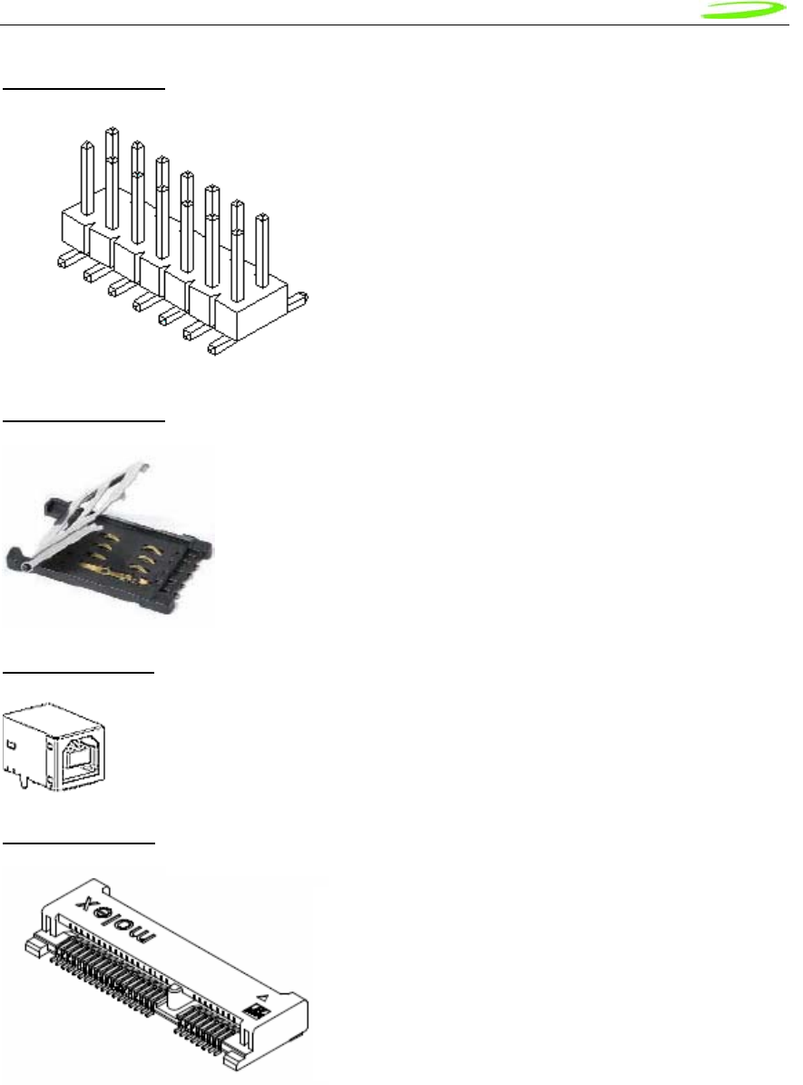
JTAG Connector
SIM Card Holder
USB Connector
Minicard Holder
A SIM card holder is provided to allow minicard software to test the
SIM interface. An ESD protection diode array is placed near the
SIM card holder. The holder used has a hinged cover. It does not
have a card detect switch as this signal is not supported in the
mPCI-E interface standard.
Development (non-commercail) Minicards may be
internally configured to support JTAG programming
through the mPCI-E interface connector. These
specially configured cards can be programmed
through a 2x10 pin header. The pinout of this header
conforms to industry standard JTAG pinouts. If the
JTAG LED is illuminated, it indicates that the
minicard is likely configured for JTAG operation. The
JTAG header is normally not populated with the
HDK.
The minicard’s USB interface signals are routed to a Type B USB connector
for connection to an external host. No additional signal conditioning or
protection is provided.
The minicard is installed onto the development board
by inserting the edge fingers into the 52 pin mPCI-E
host connector and then pushing the opposite end
down unti it snaps into the hold down mechanism. The
PCB of the development board is removed from the
area below the minicard to allow access to the bottom
side of the minicard.

Proprietary & Confidential 24
Novatel Wireless Doc No. OM-01017857 Rev 1
Pin Headers
A number of signals from the minicard can be manipulated manually by installing or removing
shorting plugs from pin headers. They are described below:
Signal Reference Shunt On Shunt Off
PS_HOLD P2-1 P2-2 Force high Normal mode
WDOG P2-3 P2-4 Watchdog disabled Watchdog enabled
WDIS P5-1 P5-2 Force low Normal mode
PERST P5-3 P5-4 Force low Normal mode
+1.5V P5-5 P5-6 Enable 1.5V regulator Disable 1.5V regulator
Mounting Holes
The board has 4 mounting holes, one at each corner, with rectangular geometry. The plated
through holes accommodate #6-32 screws and are connected to the ground plane. If it is desired
to keep the board electrically insulated from the mounting platform, then non-metallic screws and
standoffs should be used.
Proprietary & Confidential 25
Novatel Wireless Doc No. OM-01017857 Rev 1
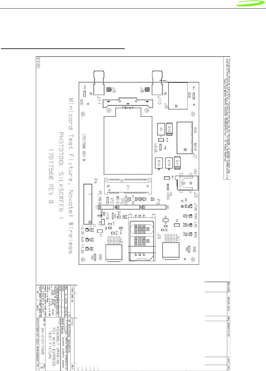
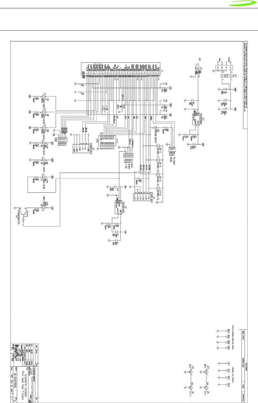
Development Board
Fixture Diagram/Assembly Diagram
Proprietary & Confidential 26
Novatel Wireless Doc No. OM-01017857 Rev 1
Photo of Top View
Proprietary & Confidential 27
Novatel Wireless Doc No. OM-01017857 Rev 1
Schematic

Proprietary & Confidential 28
Novatel Wireless Doc No. OM-01017857 Rev 1
MobiLink Phoenix SDK
SDK
Introduction
This document describes the high-level architecture and design of the Phoenix SDK. This SDK is
meant for Novatel Wireless data products.
Requirements
Single Server
Multiple Clients
Support Novatel Wireless product line
Single, Internal State Machine
Event Driven support for 2-way communication
SDK MODULES
Any number of Client applications can take full advantage of the Phoenix SDK.
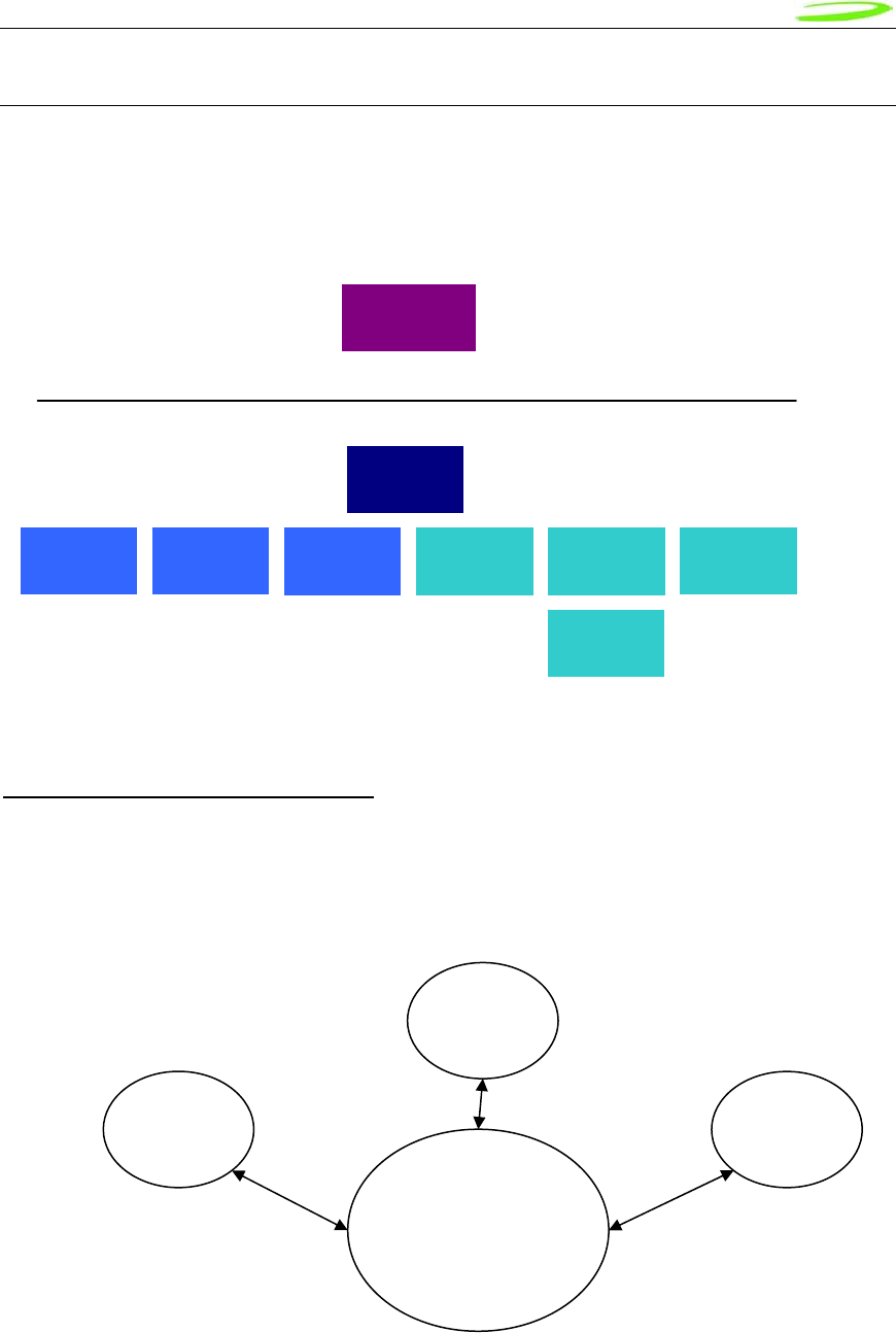
Figure 1: Applications
Phoenix & Blaze
Phoenix is the brains of the SDK. Phoenix maintains a single state machine which all Clients
communicate with. Anything and everything involving communication to the device takes places
through the Phoenix server. Implemented as a Document/View executable supporting
automation, the Phoenix server automatically keeps a count of how many Clients are attached to
it via COM interfacing. The server is initialized automatically once the first Client is instantiated
and shut down once the last Client instance is terminated. With the beauty of OLE Automation,
the Phoenix server can be utilized using many different programming languages, including C++,
MFC, JavaScript, VBScript, etc. Refer to Phoenix.chm for API documentation. If wanting to use
Phoenix in Visual Studio, import the type library Phoenix.tlb and create a wrapper class for it.
Applications
ActiveX
MobiLink
UCM SMS Client Address
book Web
Update
Profile
Manager Hotspot
Finder Menu
Utilities
NetMonk
ey
Phoenix
& Blaze

Proprietary & Confidential 29
Novatel Wireless Doc No. OM-01017857 Rev 1
Blaze ActiveX control helps Client applications to receive events fired by the Phoenix server.
This allows for simple 2-way communication, replacing redundant loop checking used in the past.
Refer to Blaze.chm for API documentation. If wanting to use Blaze ActiveX control in Visual
Studio, add the NVTL Blaze control from the registered Components and Controls Gallery and
create a wrapper class for it.
Sample Code: Refer to PhoenixClient VC++/MFC Project
NetMonkey
NetMonkey ActiveX control provides interfaces to some very useful networking components for
managing WLAN, LAN, & WWAN. The WLAN component utilizes Windows XP’s Wireless Zero
Config when managing and configuring Wi-Fi access points for seamless and easy-to-use
access. Currently, the WWAN component supports only Novatel Wireless products, given the
proper NDIS drivers. Refer to NetMonkey.chm for API documentation.
Profile Manager
Profile Manager ActiveX control helps to manage many types of WWAN network configurations
needed in order to make successful connections to a network. Mostly utilized by UMTS/HSDPA
networks, it provides a means to store settings like PDP type, PDP Address, APN, Quality of
Services settings, IP addresses, proxy settings and more. Each profile is maintained in a local
database in a proprietary XML format. Profile properties allow for seamless use via the Phoenix
server API. Refer to ProfileManager.chm for API documentation.
Hotspot Finder
Hotspot Finder ActiveX control, given a database directory of Wi-Fi hotspots, provides a simple
GUI which allows the end-user to easily refine searches in order to find the closest Wi-Fi hotspot.
Refer to Hotspots.chm for API documentation.
Menu
Menu ActiveX control, currently used in MobiLink, provides a set of GUI’s for the end-user. The
Properties dialog displays details relating to the currently selected device. The Configuration
dialog provides a means to change certain UI settings, as well as change a limited amount of
WWAN, WLAN, and LAN settings. The Report dialog shows connection logs and statistics, while
the Unlock dialog provides a UI for unlocking the current device. Lastly, the Activation dialog
provides a step-by-step Wizard for the user to activate his or her device, while the Debug dialog
provides immediate network debugging information for technical support. Refer to Menu.chm for
API documentation. (Debug Info and Activation work in progress)
Utilities
Utilities ActiveX control mainly provides a set of Novatel Wireless proprietary utility components.
Currently available is the Language component, which provides a set of translations for a number
of languages. Components involving any kind of UI take advantage of the Language component
in order to support localization. Refer to Utilities.chm for API documentation.
Proprietary & Confidential 30
Novatel Wireless Doc No. OM-01017857 Rev 1
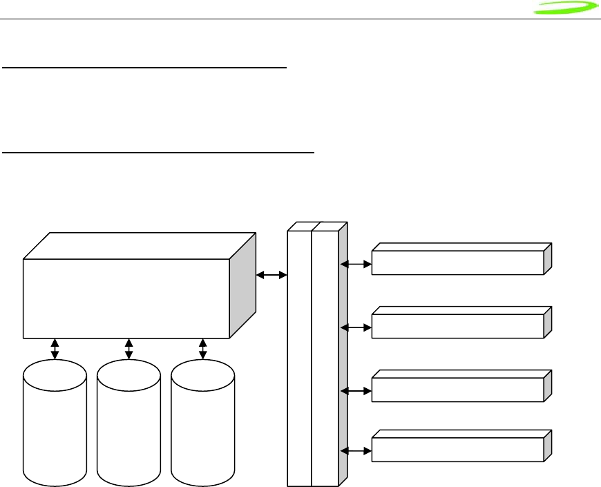
PHOENIX SERVER Software design
Overall module design is shown below.
Figure 2: Module Design
Single Server and Multiple Clients
Server-Client design has been implemented using COM and OLE Automation.
Figure 3: Automation Server
Universal
Loader
Phoenix
RAS
SMS Address
Book
PnP
Detection
ActiveX
Modules
DebugLo
g
Main
State
##Debug
Automation
Server
MobiLink
Menu
3r
d
Party
App
Proprietary & Confidential 31
Novatel Wireless Doc No. OM-01017857 Rev 1
Novatel Wireless Product Line Support
Customer driven product line will be support via the Universal Loader which will allow Phoenix a
generic means of communication to all products.
State Machine with 2-Way Communication
Figure 4: State Machine
MobiLink
Menu ActiveX
SMS Client
Serve
r
-Client Communication La
y
e
r
Methods
,
Pro
p
erties
,
and Events
Main Thread maintaining
device status and states
Phoenix server
Address
Book
Caching
SMS
message
caching
Universal
Loader
Events
3r
d
Part
y
A
pp
lication
Proprietary & Confidential 32
Novatel Wireless Doc No. OM-01017857 Rev 1
Product Overview
The purpose of this section is to provide a high level overview of the EU860D & EU870D HSDPA
and E725 EVDO module.
HSDPA Module Overview
The EU860D is primarily targeted for the North American market while the EU870D is primarily
targeted for the European market. They are both wireless modem modules designed to be
embedded into laptop computers and other host devices.
The EU870D will operate in the 850/900/1800/1900 GPRS/EDGE bands and in the
850/1900/2100D UMTS/HSDPA band. The 2100 band supports receive diversity as indicated by
the “D” appended to the bands frequency. The EU870D is built on the MSM6280/RF Platform D
chipset from Qualcomm™ with Equalizer and receive Diversity supported. This product will be
commercially launched operating up to 3.6 Mbps and will be capable of future upgrade to
7.2Mbps.
The EU860D will operate in the 850/900/1800/1900 GPRS/EDGE bands, and 850D/1900D/21200
UMTS/HSDPA band. The 850D/1900D bands supports receive diversity as indicated by the “D”
appended to the bands frequency. The EU860D is built on the MSM6280/RF Platform D chipset
from QualcommTM with Equalizer and receive Diversity supported. This product will be
commercially launched operating up to 3.6 Mbps and will be capable of future upgrade to
7.2Mbps.
The modules will be compatible with Windows™ compliant applications including VPN, e-mail,
and web browsing.
The core protocol stack will be supplied by Qualcomm™ and contains UMTS, HSDPA, GPRS
and EDGE technologies. Around this core, Novatel Wireless has created the firmware drivers that
provide access to the hardware on the embedded modem. The feature set is comprised of the
data device features supported in the Qualcomm™ protocol stack.
The hardware consists of a PCI Express Mini Card compliant interface (except as detailed
herein), a baseband chipset from Qualcomm™, an RF radio chipset from Qualcomm™, and the
various other components used to support these major components.

Proprietary & Confidential 33
Novatel Wireless Doc No. OM-01017857 Rev 1
HSDPA Module Key Feature List
• Release 5 HSDPA Category 6
o Triband- UMTS/HSDPA 850/1900/2100
o Up to 3.6 Mbps DL
o Up to 384Kbps UL
• EDGE/GPRS class 12
• Quadband- GPRS/EDGE 850/900/1800/1900
• GPS
• SIM/USIM
• MobiLink and SDK available for third party dashboards
• Advanced HSDPA equalizer support
• HSDPA Category 8 (7.2 Mbps DL) Upgrade based on Qualcomm (Rel. 4.x Dec. 2006)
Proprietary & Confidential 34
Novatel Wireless Doc No. OM-01017857 Rev 1
EVDO Module Overview
The E725 will operate in the 800/1900 CDMA bands. The E725 is primarily targeted for the North
American market.
The modules will be compatible with Windows™ compliant applications including VPN, e-mail,
and web browsing.
The hardware will consist of a Mini PCI express interface, a baseband chipset from Qualcomm™,
an RF radio chipset from Qualcomm™, and the various other components used to support these
major components. The baseband and firmware will be based on the MSM6800 series chipset.
The core protocol stack will be supplied by Qualcomm and will contain CDMA, CDMA 1XRTT,
and CDMA 1XEV-DO, and 1XEVDO Rev A technologies. Around this core, Novatel Wireless will
create the firmware drivers that provide access to the hardware. The feature set supported in
the E725 will be data device features supported in the Qualcomm protocol stack.

Proprietary & Confidential 35
Novatel Wireless Doc No. OM-01017857 Rev 1
Network Overview
HSDPA (High Speed Downlink Packet Access)
HSDPA is based on WCDMA and is standardized as part of 3GPP Release 5 WCDMA
specifications. The new modulation method improves system capacity and increases user data
rates in the downlink direction. Key performance improvements are:
• Adaptive modulation and coding
• Fast packet scheduling function as controlled by the Node B (base station or BTS), rather
than by the radio network controller (RNC).
• Fast retransmissions (HARQ-Hybrid Automatic Repeat Request) with incremental
redundancy
The WCDMA system normally carries user data over dedicated transport channels, or DCHs.
HSDPA introduces a new transport channel type, High Speed Downlink Shared Channel (HS-
DSCH) that makes efficient use of radio frequency resources and accounts for bursty packet
data. The High Speed Downlink Shared Channel (HS-DSCH) shares multiple access codes,
transmission power and also shares infrastructure hardware between several users. The radio
network resources can efficiently serve a large number of users who are accessing bursty data.
EVDO Rev A (Evolution Data Optimized)
1xEV-DO is a "3G" CDMA standard. EVDO stands for EVolution, Data-Only. 1xEV-DO is based
on a technology initially developed by Qualcomm. The international standard is IS-856. There are
currently two main versions of 1xEV-DO: "Release 0" and "Revision A".
1xEV-DO allows mobile terminals with data rates of up to 2.4576 Mb/s with Rev. 0. EVDO
provides data rates over 10 times faster than 1xRTT, the previous data technology for CDMA
networks. It is available where CDMA voice service is available.
EVDO Rev. A:
• Maximum downlink (forward link) data rate of 3.1 Mb/s
• Uplink rate of from 0.15 Mb/s to 1.8 Mb/s.
• Fast packet establishment on the forward and reverse links
• Air interface enhancements with
o Reduce latency
o Improved data rates.
EV-DO Rev. A supports low latency services including VoIP and Video Telephony.

Proprietary & Confidential 36
Novatel Wireless Doc No. OM-01017857 Rev 1
Application Software Overview
MobiLink™ connection manager
Novatel Wireless provides Mobilink™ application software. The software is defined in later
Chapters.
MobiLink™ connection manager software to install and configure modem (for all supported
platforms)
Key Features
• AT Command Set Support per IS-707
• Fully compatible and interoperable with current Microsoft™ OS platforms: PPC
2000/2002/HPC, Windows 98, Windows 2000, Windows ME, & Windows XP
• Integrated drivers for Windows OS, configurable as either a modem or network
card
• PCI Express Mini-card
• Compatibility with all major brands of PC's and PPC computing platforms
• Sleep Mode capabilities
• Uses common base technology shared with OEM Module
• IS-683A compliant - Over-The-Air activation and parameter update capabilities.
• On-line help, getting started guide, documentation
• All software applications necessary to communicate with the PCI Express Mini
Card will operate with the following platforms: PPC 200/2002/HPC, Windows 98,
Windows 2000, Windows ME, & Windows XP
• All software shall support 640x480, 640x240, and 800x600 color and
monochrome displays
• MobiLink allows the user to configure the modem easily
• MobiLink provides diagnostic capability
• MobiLink provides a Help menu that is Context Sensitive

Proprietary & Confidential 37
Novatel Wireless Doc No. OM-01017857 Rev 1
Device Specifications
PCI Express Mini Card
Novatel Wireless has designed a line of embedded broadband access modules around the PCI
Express Mini Card Specification 1.11 . This product line provides platform developers and system
integrators with the ability to enable global 3G broadband access. The governing body for PCI
Express standardization is PCI SIG (Peripheral Component Interconnect Special Interest Group.)
The website for PCI SIG can be found at the following URL:
www.pcisig.com/home
1 Customizations that deviate from the PCI Express Card Electromechancil Specification revision 1.1 are noted in this
document

Proprietary & Confidential 38
Novatel Wireless Doc No. OM-01017857 Rev 1
Hardware
Card Specifications
The E725, EU860D and EU870D are designed to meet the PCI Express Mini Card electro-
mechanical card standard with some exceptions to accommodate the power requirements. These
modules all support only the USB portion of the minicard standard.
Chipset
E725
The Qualcomm MSM6800 baseband processor, PM6650 power management IC, RFT6150, and
the RFR6500 shall be the chipset used.
EU860D
The HSDPA PCI Express Mini-card baseband incorporates the Qualcomm MSM6280 baseband
processor and the PM6650 power management IC. The EU860D North American RF deck
consists of the Platform D (Rx Diversity) chipsets, RTR6275, and the RFR6500.
EU870D
The HSDPA PCI Express Mini-card baseband incorporates the Qualcomm MSM6280 baseband
processor and the PM6650 power management IC. The EU870D Euro RF deck consists of the
Platform D (Rx Diversity) chipsets, RTR6275, and the RFR6525.

Proprietary & Confidential 39
Novatel Wireless Doc No. OM-01017857 Rev 1
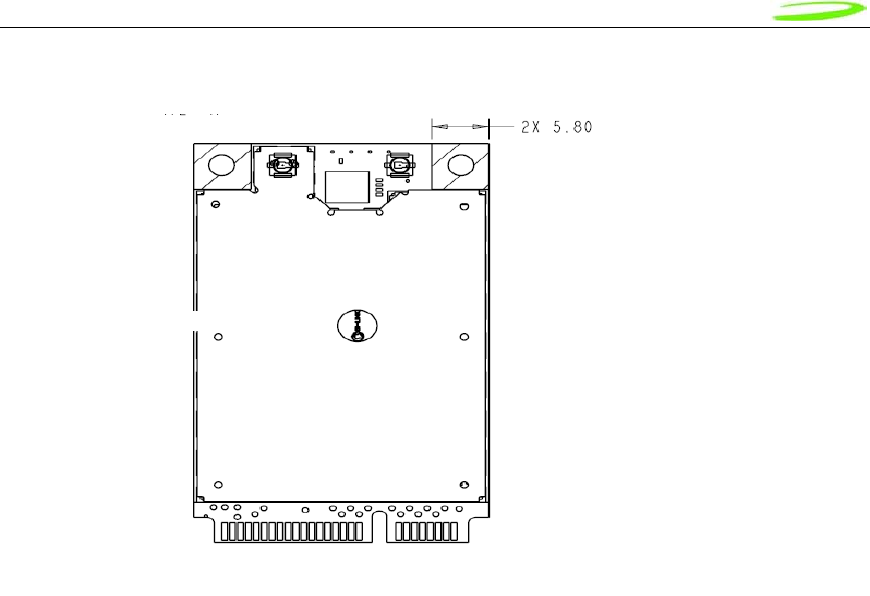
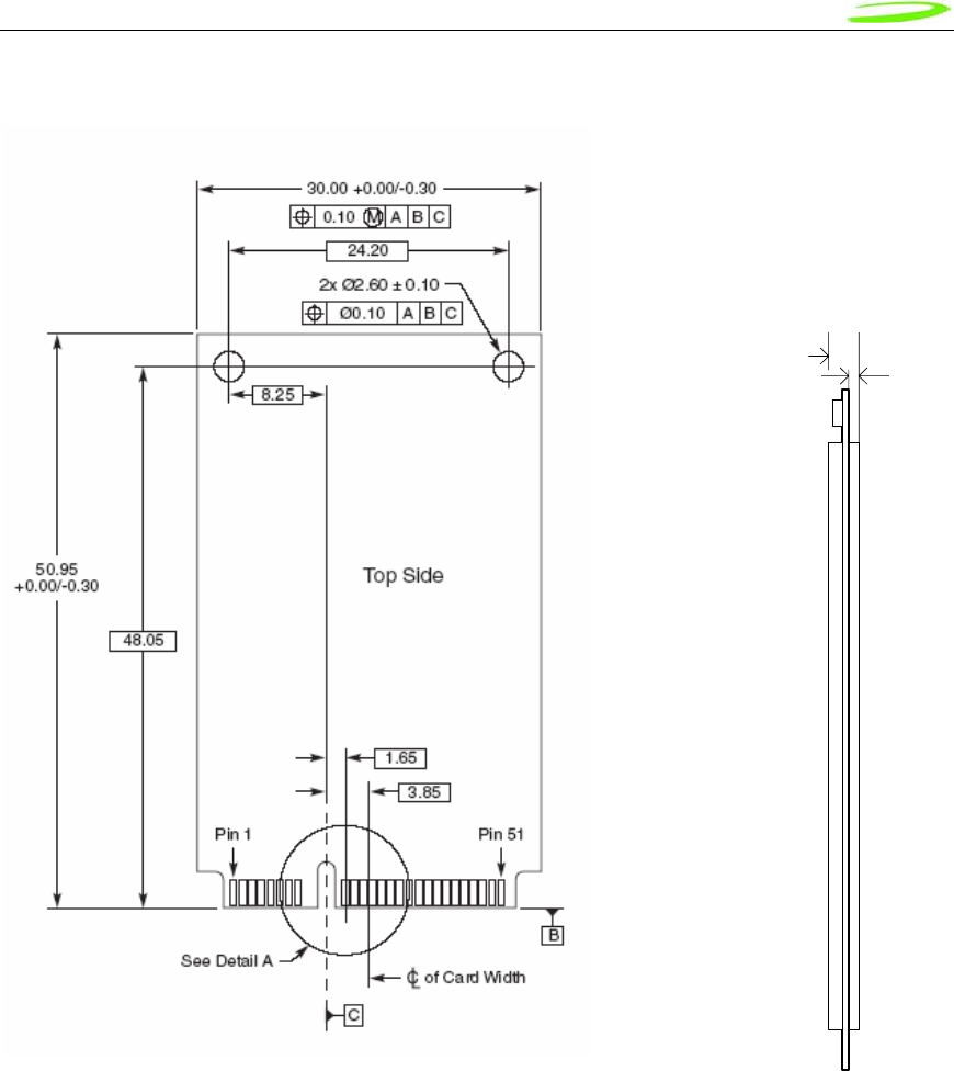
Mechanical Specification
The drawing in Figure 5 to Figure 7 shows the dimensions of the E725 & EU860D/EU870D
modules. The measurements given below are typical. Consider thickness to be 5.0 max in
designing. Note that EU860D/870 antenna connection and final dimensions will be detailed in
next release of this handbook. Figures 6 and 7 show detail associated with the shielding used on
the EU730/EU740. The EU860D and EU870D will use metal shields.
RF (Antenna) connector
The two RF connectors used are Hirose U.FL-R-SMT or equivalent.
Host Interface connector
The host interface connector is a 1 mm wide card edge connector. This is compatible with the
following host connectors:
Molex 67910-0002
The host connector should be compliant with the Mini PCI express Electromechanical
specification.
Shielding / Mechanical enclosure
The EU860D and EU870D use metal shield technology. The shield dimensions are presently
under revision and the high side/low side thickness dimensions and tolerances will be updated in
next release of this guide.
The E725 will use a stamped sheet metal shield technology. The shields are held in place with
solder.
Proprietary & Confidential 40
Novatel Wireless Doc No. OM-01017857 Rev 1
Figure 5: E725 Module
All Dimensions in mm
Proprietary & Confidential 41
Novatel Wireless Doc No. OM-01017857 Rev 1
Figure 6: EU860D/EU870D Module
Proprietary & Confidential 42
Novatel Wireless Doc No. OM-01017857 Rev 1
Figure 7: EU860D/EU870D Module
Proprietary & Confidential 43
Novatel Wireless Doc No. OM-01017857 Rev 1
Figure 8: PCIe Minicard Module Envelope
1.35 mm
5.0 mm
Proprietary & Confidential 44
Novatel Wireless Doc No. OM-01017857 Rev 1
Interface Specification
Host Interface
The E725 and EU860D/870D are designed to meet the PCI Express Mini-Card specification. The
table below gives a description of the pin-out and usage. The USB option of the specification is
supported. Deviations from the Mini PCI Express card specification 1.1 are noted.
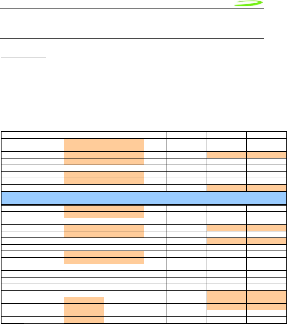
Host Interface specification
Pin PCIe Spe
c
EVD
O
HSDPA Pin PCIe Spe
c
EVD
O
HSDPA
1 WAKE# NC NC 2 3.3V 3.3V 3.3V
3 Reserved NC NC 4 GND GND GND
5 Reserved NC NC 6 1.5V NC NC
7 CLKREQ# NC NC 8 UIM_PWR UIM_PWR UIM_PWR
9 GND GND GND 10 UIM_DATA UIM_DATA UIM_DATA
11 REFCLK- NC NC 12 UIM_CLK UIM_CLK UIM_CLK
13 REFCLK+ NC NC 14 UIM_RESET UIM_RESET UIM_RESET
15 GND GND GND 16 UIM_VPP NC NC
17 Reserved NC NC 18 GND GND GND
19 Reserved NC NC 20 W_DISABLE# W_DISABLE# W_DISABLE#
21 GND GND GND 22 PERST# PERST# PERST#
23 PERn0 NC NC 24 +3.3Vaux NC NC
25 PERp0 NC NC 26 GND GND GND
27 GND GND GND 28 +1.5V NC NC
29 GND GND GND 30 SMB_CLK SMB_CLK SMB_CLK
31 PETn0 NC NC 32 SMB_DATA SMB_DATA SMB_DATA
33 PETp0 NC NC 34 GND GND GND
35 GND GND GND 36 USB_D- USB_D- USB_D-
37 Reserved GND NC/GND 38 USB_D+ USB_D+ USB_D+
39 Reserved 3.3V 3.3V 40 GND GND GND
41 Reserved 3.3V 3.3V 42 LED_WWAN# LED_WWAN# LED_WWAN#
43 Reserved GND GND 44 LED_WLAN# NC NC
45 Reserved NC NC/PCM_CLK 46 LED_WPAN# NC NC
47 Reserved NC NC/PCM_SYNC 48 +1.5V NC NC
49 Reserved NC NC/PCM_DOUT 50 GND GND GND
51 Reserved NC NC/PCM_IN 52 3.3V 3.3V 3.3V
Mechanical Key
Notes: NC No Connect
W_DISABLE Radio Transmit Disable
NC/XXXX Standard product will have No Connect, Population option,
PCM_XXXX PCM Voice interface (Data in, Data out, Sync & clock)

Proprietary & Confidential 45
Novatel Wireless Doc No. OM-01017857 Rev 1
USB Interface
The Mini card acts as a peripheral device and supports the USB 2.0 standard at low speed (1.5
Mbps) and full speed (12 Mbps). It does not support the high speed (480 Mbps) mode of
operation.
Subscriber Identification Module (SIM) Interface (EU860D/EU870D only)
A 4 line SIM interface is provided on the mini-card edge connector for the EU860D/860. The
signal levels comply with the ETSI standard Specification of the 3 Volt Subscriber Identity Module
- Mobile Equipment (SIM-ME) interface (GSM 11.12 version 4.3.1). Note that no ESD protection
will be provided on the mini-card. The host device is expected to provide the ESD protection at
the SIM connector.
The OEM Module supports a 3.0V SIM as described in ETSI 11.12. The relevant signals are
brought out on the 70 pin connector.
• The SIM interface shall support 1.8 V USIMs
• The SIM interface shall support 3.0V USIMs
• The SIM interface shall support 3.0V SIMs
The USIM will be provided by the host. A SIM connector is not included on the mini-card. The
interface to the USIM is provided on the host interface connector. A recommended interface card
design criteria is available from Novatel. Please refer to the Integrator Design Elements:
Antenna, Power & SIM section for further details.
WDISABLE
The modem is made incapable of transmitting when the WDISABLE pin is pulled low. The
following diagram illustrates the Pull-Up resistor configuration:
Figure 9: W_Disable Pull-up Configuration
The W_DISABLE# signal from the host interface connector is used to control the operational
status of the radio transmitter. When it is high, the radio is made capable of transmitting. When it
is low, the radio is made incapable of transmitting by removing the various power supplies.
W
_
DISABLE # (Pin 20)
GPIO
E725, EU860 & EU870 W_DISABLE# Circuit
MSM680
0
V
_
CC
>40k
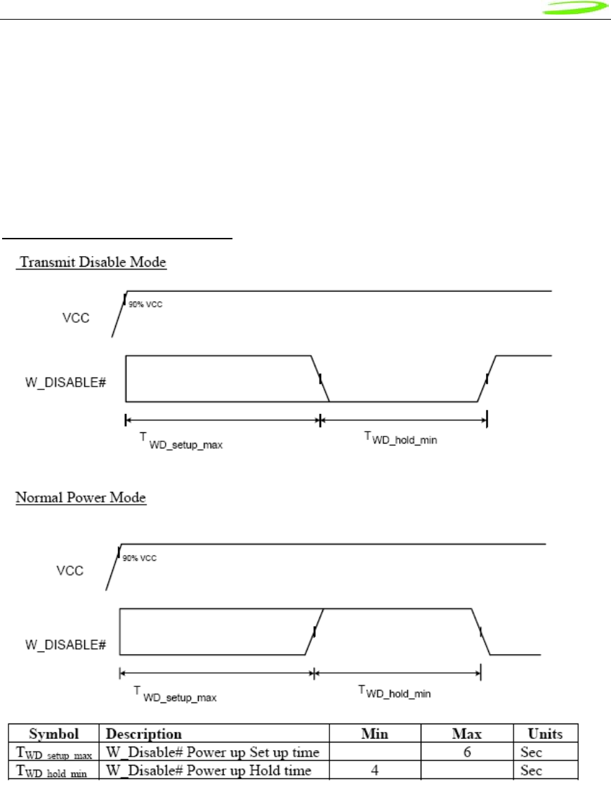
Proprietary & Confidential 46
Novatel Wireless Doc No. OM-01017857 Rev 1
HSDPA Module Operation
During normal operation, the W_DISABLE# signal is high. When the host asserts the
W_DISABLE# signal low, an interrupt is generated which executes power down routines such as
saving any required data. The software programs the power management device (PM6650) to
selectively disable voltage regulators in order to render the Mini Card incapable of transmitting.
W_DISABLE# signal from the host may be asynchronously applied to the E725, EU860 & EU870.
W_DISABLE Power Up Timing
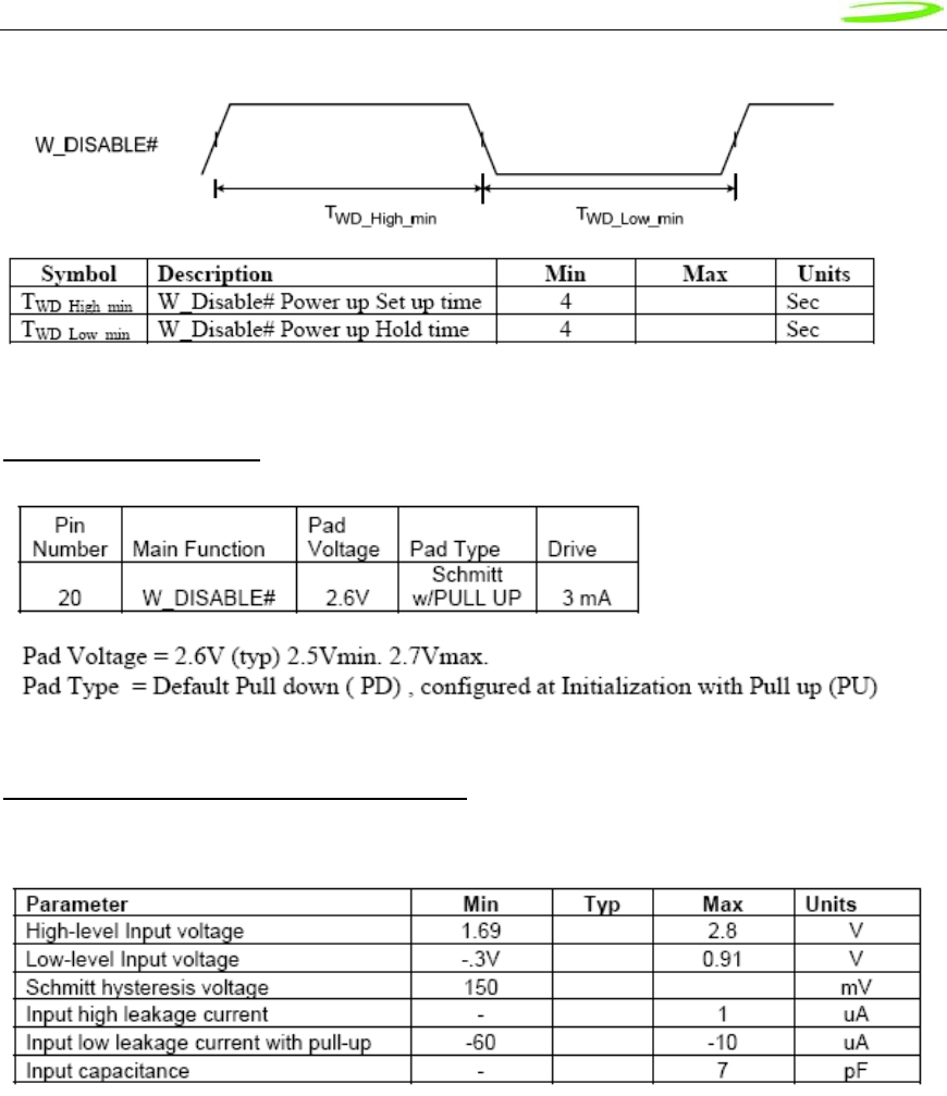
Proprietary & Confidential 47
Novatel Wireless Doc No. OM-01017857 Rev 1
W_Disable # Interface
E725 W_Disable # Pin Characteristics
W_DISABLE#

Proprietary & Confidential 48
Novatel Wireless Doc No. OM-01017857 Rev 1
LED Interface
A signal for the WWAN LED shall be available on the host connector. The LED cadence
shall support one of 3 schemes which shall be selectable using an NV item:
Scheme 1:
State LED function
On The WWAN radio is on, and capable of transmitting
Off The WWAN radio is not capable of transmitting.
Scheme 2:
State LED function
Off Not powered
On Powered, associated and authenticated but not transmitting or receiving
Slow Blink Powered but not associated or authenticated; searching
Intermittent blink Activity proportional to transmitting/ receiving speed
Scheme 3:
State LED function
Off Not powered
On Connected
Slow Blink No SIM Card, Out of range
Intermittent blink Activity proportional to transmitting/ receiving speed
SM Bus Interface
A 2 line SM Bus shall be supported using the designated pins on the host interface.
The card shall support SM Bus as a master only. Please refer to the SM Bus Design Guidelines
section for further details.
PCM Voice Interface
A 4 line PCM voice interface shall be provided as a population option. Please contact Novatel
Wireless for details on the support of this feature.
JTAG Interface
A JTAG interface is available to support development activities. The JTAG interface shall not be
available for customer use.

Proprietary & Confidential 49
Novatel Wireless Doc No. OM-01017857 Rev 1
Power Supply
The card shall operate within specification for the voltage range of 3.00 to 3.56 V with the nominal
voltage being 3.3 V. Current is drawn from the 3.3V pins on the Mini Card connector as shown in
tables following.
Idle/Low Power Mode Current
Symbol Parameter Min Typ Max Units
Icc Idle/Standby
HSDPA/UMTS/EDGE/GPRS No connection to host,
Driver not active. (Note 1) 50 mA
Icc Low Power Mode
HSDPA/UMTS/EDGE/GPRS USB Selective Suspend
With SIM
Without SIM
Connection to host,Driver
active, (Note 1)
20
10
mA
mA
Icc Idle/Standby
EVDO
USB Suspend TBD mA
Icc Low Power Mode
EVDO
USB Selective Suspend TBD mA
Note1: Test conditions: Temperature: 25 degree Celsius
Supply voltage: 3.3V
Note 2: Forward looking estimates based on existing platforms. Actual values to be provided once available.
Peak Current
Symbol Parameter Min Typ Max Units
Icc peak_GPRS Peak current 2750
(Note 2) A
Icc peak_HSDPA_UMTS Peak current 1000 mA
Icc peak_EDGE Peak Current 1000 mA
Icc peak_EVDO Peak Current 1000 mA
Note 1: Test conditions:
1. VSWR 4:1
2. Temperature: 25 degree Celsius
3. Supply voltage 3.3V
Note 2: Forward looking estimates based on existing platforms. Actual values to be provided once available.
Blocked antenna condition creating a VSWR greater than 4:1 may create a condition where the
transmitted power increases and currents peak drawn in GPRS/EDGE mode exceed 2.750 Amps
Estimated current consumption during transmit periods is shown in the following table.

Proprietary & Confidential 50
Novatel Wireless Doc No. OM-01017857 Rev 1
Transmit Power Consumption
Band Technology Power
Class Spec Set Point 3.3V rail
dBm dBm Avg mA Peak
(Note 1)
Band I WCDMA/HSDPA 3 24 +1/-3 23 <1000
Band II WCDMA/HSDPA 3 24 +1/-3 23 <1000
Band IV WCDMA/HSDPA 3 24 +1/-3 24 <1000
GSM850 GPRS 4 33 +/- 2 33 <500 < 1800
EDGE E2 27 +/- 3 27 <500 < 1800
GSM900 GPRS 4 33 +/- 2 33 <500 < 1800
EDGE E2 27 +/- 3 27 <500 < 1800
GSM1800 GPRS 1 29 +/- 2 30 <500 < 1800
EDGE E2 26 +/- 3 26 <500 < 1800
GSM1900 GPRS 1 29 +/- 2 30 <500 < 1800
EDGE E2 26 +/- 3 26 <500 < 1800
Cellular EVDO 24 <700
PCS EVDO 24 <800
Note 1 GPRS: 2750mA Max into 4:1 VSWR
Note 2 Forward looking estimates based on existing platforms. Actual values to be provided once available.
Proprietary & Confidential 51
Novatel Wireless Doc No. OM-01017857 Rev 1
Power Class
The power class of the PCI Express Mini cards are detailed in the following table.
Band Technology Power
Class Spec Set Point Delta1
dBm dBm EU730/
EU740
Band I 2100 WCDMA/HSDPA 3 TS 25.101 24 +1/-3 23
Band II 1900 WCDMA/HSDPA 3 TS 25.101 24 +1/-3 242 +3
Band IV 850 WCDMA/HSDPA 3 TS 25.101 24 +1/-3 242 +3
GSM850 GPRS 4 TS 51.010 33 +/- 2 332 +1
EDGE E2 TS 51.010 27 +/- 3 27
GSM900 GPRS 4 TS 51.010 33 +/- 2 332 +1
EDGE E2 TS 51.010 27 +/- 3 27
GSM1800 GPRS 1 TS 51.010 30 +/- 2 302 +1
EDGE E2 TS 51.010 26 +/- 3 26
GSM1900 GPRS 1 TS 51.010 30 +/- 2 302 +1
EDGE E2 TS 51.010 26 +/- 3 26
CDMA Class III Per IS-98D 23-30 24
CDMA 1XRTT Class III Per IS-98D 23-30 24
Cellular
824-849 (Tx)
869-894 (Rx)
CDMA 1XEV-DO Class III Per IS-98D 23-30 24
CDMA Class II Per IS-98D 23-30 24
CDMA 1XRTT Class II Per IS-98D 23-30 24
PCS
1850-1910 (Tx)
1930-1990 (Rx)
CDMA 1XEV-DO Class II Per IS-98D 23-30 24
Note 0: The maximum power factory calibration tolerance is +0.7dB for both technologies
Note 1: Delta on transmit power from EU730/EU740 in dBm.
Note 2: Novatel Wireless reserves the right to change the set point for transmit power in order to
resolve integration issues in order to meet system requirements as input power, thermal
dissipation and SAR requirements. The transmit power set point was selected in order to
meet expected system TRP requirements from the carriers.

Proprietary & Confidential 52
Novatel Wireless Doc No. OM-01017857 Rev 1
Conducted Sensitivity
The estimated conducted Sensitivity is detailed in the following table.
Conducted Sensitivity
GPRS
EDGE
WCDMA
EVDO
dBm dBm dBm dBm dBm dBm dBm dBm
Band Spec #1 Typ Spec #2 Typ Spec Typ Spec Typ
850 -99 -86 -104.7 -104
900 -99 -86
1800 -97 -86
1900 -99 -86 -104.7 -104
2100 -106.7
Note 1: 51.010 14.18 PDTCH MCS-4
Note 2: 51.010 14.18 PDTCH MCS-9
Note 3: Contact Novatel Wireless for typical values to enable prediction of integrated TIS values.
Note 4: Factory test limits typically 2-3 dB beyond Specified Limits. Typical sensitivity will have
additional margin above Factory Test Limits.

Proprietary & Confidential 53
Novatel Wireless Doc No. OM-01017857 Rev 1
Antenna
The enhanced antenna feature supports:
• SAIC (Single Antenna Receiver Interference Cancellation) – R2.x, R4.x
• Rx Diversity, Equalizer – R4.
Antenna Connectivity Comparison
HSDPA EVDO
Primary Antenna Primary Antenna
HSDPA Band I Cellular Band 0
HSDPA Band II PCS Band 1
HSDPA Band IV
QB GPRS/EDGE
Diversity Antenna Diversity Antenna
HSDPA Band I or Band II Diversity Cellular Band 0
HSDPA Band IV Diversity PCS Band 1
GPS GPS
The RF connectors shall be Hirose U.FL-R-SMT or equivalent. This connector is designed for a
limited number of insertions. For an embedded application this is expected to be acceptable. The
antenna interface shall be as defined below:
EU870D EU860D E725
UMTS Tx_Rx UMTS Tx_Rx Cellular Band 0
GPRS/EDGE GPRS/EDGE PCS Band 1
RF Connector (main)
UMTS 850/2100 Rx UMTS 850/1900 Rx Cellular Band 0
GPS GPS PCS Band 1
GPS
RF Connector
(Diversity)
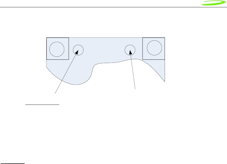
Proprietary & Confidential 54
Novatel Wireless Doc No. OM-01017857 Rev 1
The connector location shall be as shown below:
The E725 and EU860/870 are designed to be connected to an external antenna integrated into
the host system. The antenna port presents a nominal 50Ω impedance.
Diversity
The EU860D shall support diversity on the UMTS/HSDPA 850 and 1900 bands. Roaming onto
the 2100 band is supported.
The EU870D shall support diversity on the UMTS/HSDPA 2100 bands. Roaming onto the 850
and 1900 bands is supported.
The EU870D/EU860D shall operate in the 850/900/1800/1900 GPRS/EDGE bands
Diversity is not supported in the GPRS/EDGE bands.
The E725 supports receive diversity in the 800/1900 bands.
Diversity/GPS Primary

Proprietary & Confidential 55
Novatel Wireless Doc No. OM-01017857 Rev 1
GPS
E725 EU860D/EU870D
GPS is supported. GPS is supported.
The EVDO Rev. A and HSDPA module receives GPS signals on the diversity antenna.
The EVDO Rev A and HSDPA module will support the following GPS features to the extent the
associated application and network also supports the operation of the features identified below.
Thus some of the features will not be operational until the application and/or network support is
available.
GPS Features
• GPS Standalone runs well without network
• GPS MS-Based gives fast fix and better sensitivity - requires periodic PDE support
• GPS MS-Assisted best coverage and best accuracy - requires constant PDE support
• GPS Control Plane network service completion
• GPS SMS Remote initiation with service payload for GPS tracking (planned)
GPS Application Services
• Simultaneous GPS fix and data session
• Autonomous GPS with caching of ephemeris and last fix
• Interfaces
– Serial NMEA interface pass-through
• MobiLink API for location request, tracking
– SMS Activated Location Responder
– GPS Timer and Fencepost trigger
• Application
– Common GPS client on host device
– Popular Adapters to Browser, Map, Traffic & POI client apps
– Vertical Market Subsystem enabler – client tracking & fixing
– Possible Location Server / Dispatch Assist

Proprietary & Confidential 56
Novatel Wireless Doc No. OM-01017857 Rev 1
Firmware
Overview
The firmware for the EU860D/870 is comprised of the Qualcomm™ supplied UMTS/GPRS
protocol stack (Advanced Mobile Subscriber Station (AMSS) 6275 Software) with additional
Novatel Wireless firmware specific to the Mini Card implementation. The firmware runs on ARM9
core in the MSM6280 ASIC.
The firmware for the E725 is comprised of the Qualcomm™ supplied protocol stack (Advanced
Mobile Subscriber Station (AMSS) 6800 Software) with additional Novatel Wireless firmware
specific to the Mini card implementation. The firmware runs on ARM9 core in the MSM6800
ASIC.
Memory
In order to reduce the MSM6275 and the MSM6500 firmware memory footprint, unused
application features, drivers and services are removed. The network protocol layers (Mobility
Management, Data services, Radio Resource Control, Radio Link Control, Media Access Control,
Physical Layer control and Drivers to Qualcomm™’s RF chipsets) remain unaltered.
EU860D/870 Firmware Features
HSDPA & UMTS Protocol and Features
General
• Triband- UMTS/HSDPA 850/1900/2100
HSDPA
• Release 5 HSDPA Category 6
o Up to 3.6 Mbps DL
o Up to 384Kbps UL
• Advanced HSDPA Equalizer support
• HSDPA Category 8 (7.2 Mbps DL) Upgrade based on Qualcomm (Rel. 4.x Dec. 2006)
• 3.6 Mbps HSDPA data cards with (Release 4.0E)
• DCCH 3.4 Kbps
• Establish/ Release/ Reconfigure of HSDPA channel
• HSDPA channel re-pointing (Synchronized and non- synchronized cell change) for
mobility.
• Up switching and Down switching of PS RAB between DPCH and HS- DSCH
• Switching between HSDPA channel and common channel
• Integrity protection and ciphering
• Primary PDP context.
• HSDPA Protocol
• Uplink Channels
o HS-DPCCH (HS Dedicated Physical Control Channel)
o • CQI (Channel Quality Indicator)
o • Scheduling downlink Packet
• • Downlink Channels

Proprietary & Confidential 57
Novatel Wireless Doc No. OM-01017857 Rev 1
• HS-SCCH (HS Shared Control Channel)
• Channelization code set
• Modulation scheme
• Transport block size
• HARQ process information
• Redundancy & constellation version
• New data indicator
• HS-PDSCH (HS Physical Downlink Shared Channel)
• Category 12 (QPSK)
• Code Rates
Rate ¼
Rate ½
Rate 1/3
• HSDPA Logical Channels
HS-SCCH
HS-DPCCH
HS-PDSCH
Up to 5 HS-PDSCH channels support
• HSDPA Transport Channels
HS-DSCH
. 120 kbps
. 240 kbps
. 360 kbps
• Fast L1 HARQ
• Incremental redundancy
• Chase combining retransmission scheme
• Multi-Code Operation 1 code
5 codes
480 kbps
600 kbps
720 kbps
1.2 Mbps
1.8 Mbps
• Fast link adaptation
• Vary the effective code rate
• HARQ, MAC-HS disassembly
• MAC-HS reordering queue distribution and processing support
• Synchronous and non-synchronous cell change support
• Intra-NodeB (softer re-pointing) cell change support
• Inter-NodeB (soft re-pointing) cell change support
• Ciphering on the HS channel
• Support to not resume the HS channel if inter-RAT handover fails, but save the RB
mapping information
• Support to not resume the HS channel if a radio link failure occurs, but save the RB
mapping information
• QoS
Background QoS class supported
Interactive QoS class supported
Streaming QoS class supported
UMTS
• UMTS: 3GPP Release 5, June 2004

Proprietary & Confidential 58
Novatel Wireless Doc No. OM-01017857 Rev 1
• Cell_PCH and URA_PCH
• WCDMA-to-GPRS reselection in CELL_FACH
• 64K Sync CSD
• Radio link failure (RRC)
• Inter-frequency reselection in Cell_FACH
• SIB scheduling
• Path loss measurements
• 6F/6G (UE internal)
• Re-establishment procedure
• SIB modification
• SIB 7
• Inter-frequency redirection
• Inter-RAT redirection (RRC connection reject to GSM)
• HCS
GPRS/EGPRS Protocol and Features
General
• Quadband- GPRS/EDGE 850/900/1800/1900
GPRS
• channel coding schemes CS1-4
• link adaptation
• multislot class 12
• One-phase packet access
• Two-phase packet access
• GPRS test modes ( ETSI test mode A and B)
• Attach / Detach
GPRS detach only
Combined GPRS/IMSI detach
MS-initiated detach
NW-initiated detach
Automatic GPRS attach at power-up
GPRS attach status indication
EGPRS
• Uplink modulation and coding schemes MCS 1-4
• downlink modulation and coding schemes MCS 1-9
• 8PSK modulation on both uplink and downlink for MCS 5-9
• One-phase packet access
• Two-phase packet access
• EGPRS test modes (ETSI test mode A and B)
• EGPRS link adaptation
• EGPRS incremental redundancy
• EGPRS multislot class 12
NC0
Medium access modes – dynamic allocation
RLC-acknowledged operation mode
RLC unacknowledged operation mode
LLC-acknowledged transmission mode

Proprietary & Confidential 59
Novatel Wireless Doc No. OM-01017857 Rev 1
LLC-unacknowledged transmission mode
GSM network operation mode I
GSM network operation mode II
PBCCH/PCCCH support in NOM I
PDP Context
• Mobile-originated PDP context activation
• Mobile-originated PDP context deactivation
• Network-originated PDP context deactivation
• Network-originated PDP context activation
• PDP context modification (NW initiated)
• Active PDP context indication
• PDP address (IPv4)
• PDP address (IPv6)
• PDP context type – IP
Static IP
Dynamic IP
RFC1144 TCP/IP header compression
WINS address support-primary and secondary
• QoS
Support QoS profile (release 97)
Enhanced QoS (refer to 3GPP TS 22.060, Section 5.6.2; TS 24.008, Section 10.5.6.5)
Support QoS profile (release 99, EGPRS-capable terminals)
Background QoS class supported
Interactive QoS class supported
Streaming QoS class supported
V.42bis data compression
Carrier will be able to program GPRS service parameters (PDP context) (via Application Profile)
Data counter (time and transferred bytes per session and cumulative sessions)
Packet enhanced measurement report (PEMR)
Network-assisted cell change (R4 GERAN Feature Set 1)
Extended UL TBF mode (R4 GERAN Feature Set 1)
Security
• Support of encryption A5/1
• Support of encryption A5/2
• GPRS ciphering algorithm GEA1
• GPRS ciphering algorithm GEA2
• PAP for RADIUS authentication - GPRS/EGPRS
• CHAP for RADIUS authentication - GPRS/EGPRS
• Support for encryption algorithm UEA1 (Kasumi)
• Support for integrity algorithm UIA1 (Kasumi)
• SIM lock
SMS
• Mobile-originated SMS (MO-SMS) over CS channel
• Mobile-originated SMS (MO-SMS) over PS channel
• Mobile-originated SMS over PS shall fall back to CS if: a) PS service is not available, or
b) there is a PS network failure
• Mobile-originated SMS (MO-SMS) concatenation (minimum of 5 segments)
• Mobile-terminated SMS (MT-SMS) over CS channel

Proprietary & Confidential 60
Novatel Wireless Doc No. OM-01017857 Rev 1
• Mobile-terminated SMS (MT-SMS) over PS channel
• Mobile-terminated SMS (MT-SMS) concatenation (minimum of 5 segments)
USSD
• Unstructured supplementary service data – mobile-originated (MO-USSD)
• Unstructured supplementary service data – mobile-terminated (MT-USSD)
Network Selection
• Support for the network selection procedures described in 3G 22.011, R4 minimum
• Support for the network selection procedures described in 3G 23.122, R4 minimum
• Support for the RRC connection reject message to redirect from a 3G system to a 2G
system, according to 25.331, R4 minimum
• Support for the network selection procedures described in 3G 43.022, R4 minimum
• Support for an initial HPLMN scan at a 2mins after power on
• Support for a HPLMN rescan irrespective of the serving MCC
• Support of equivalent PLMN
• Network selection within 30 seconds upon power up
Inter-RAT and Inter-Frequency
• GSM900 Q WCDMA2100 handover – blind mode
• GSM1800 Q WCDMA2100 handover – blind mode
• GSM900 J WCDMA2100 handover – idle frame measurements
• GSM1800 J WCDMA2100 handover – idle frame measurements
• GSM900 Q WCDMA2100 cell reselection
• GSM1800 Q WCDMA2100 cell reselection
• GSM900 Q WCDMA2100 CCO
• GSM900 Q WCDMA 2100 CCO
• GSM900 (w/BCCH/ PBCCH) J WCDMA2100 reselection in packet transfer
• GSM1800 (w/BCCH/ PBCCH) J WCDMA2100 reselection in packet transfer
• PS data continuity during OOS and RAT change
• PS data continuity with MPDP (primary and secondary contexts) and RAT change
• EDGE Q WCDMA cell reselection in packet transfer
• Inter-RAT NACC 2G 1 3G
• 3G background PLMN search while in 2G
• 3G background PLMN search while in 3G
HSPDA
System
• Network Selection
• Enhanced Network Selection (ENS)
• Supplementary Services
SIM
• Dual IMSI
Fixes to Feature and Protocol deficiencies identified through testing of Beta Release
HSDPA Compressed mode with active HS channel
MAC-d de-multiplexing

Proprietary & Confidential 61
Novatel Wireless Doc No. OM-01017857 Rev 1
E725 Firmware Features
The EVD0 Rev A Firmware Features are listed below:
Standards Support
• IS-707: 14.4 kbps Data Services
• TSB-74: 14.4 kbps Radio Link Protocol and Interband Operations
• TIA/EIA/IS-2000 PN-4756 (Ballot Version): Addendum 1 (to the IS-2000 standard)
• IS-707A: CDMA Data Services Revision for IS-95B
• IS-707A-1: CDMA Data Services Revision for cdma2000 Rel. 0
• IS-95A, IS-95B: CDMA Dual-Mode Air Interface Standard
• PN-4430 (Ballot Resolution Version 0.14, to be published as TIA/EIA-IS-2000.4):
cdma2000: Signaling Layer 2 Standard for Spread Spectrum Systems
• J-STD-008: IS-95 adapted for 1900 MHz frequency band
• PN-4429 (Ballot Resolution Version, to be published as TIA/ EIA-IS-2000.3): Medium
Access Control (MAC) for cdma2000 Spread Spectrum Systems
• TIA/EIA-95-B: Mobile Station-Base Station Compatibility Standard for Dual-Mode Spread
Spectrum Systems
• IS-683A: OTA Update: Roaming System Selection and Programming Block
• PN-4428 (Ballot Resolution Version, to be published as TIA/ EIA-IS-2000.2): Physical
Layer Standard for cdma2000 Spread Spectrum Systems
• IS-637A: Short Message Service including mobile-origination
• PN-4431 (Ballot Resolution Version 1.06, to be published as TIA/EIA-IS-2000.5): Upper
Layer (Layer 3) Signaling Standard for cdma2000 Spread Spectrum Systems
• IS-856-2 (3GPP2 C.S0024): cdma2000® High Rate Packet Data Air Interface
Specification
• IS-856-A (3GPP2 C.S0024): cdma2000® High Rate Packet Data Air Interface
Specification Rev A
Frequency Band Support
• Band Class 0 – Cellular 800 MHz
• Band Class 1 – PCS 1.9 GHz
CDMA Air Interface
• TIA/EIA/IS-95-A Air Interface
• TIA/EIA-95-B Air Interface
• J-STD-008 + TSB74 Air Interface
• TIA/EIA/IS-2000-0 Air Interface
• TIA/EIA/IS-2000-A Air Interface
• TIA/EIA/IS-2000-B air interface
• TIA/EIA/IS-2000-C air interface
• TIA/EIA/IS-2001 Data Session Handoff
• TIA/EIA-126 Loop back Services
• TIA/EIA/IS-870 Test Data Services
• TIA/EIA/IS-871 Markov Services
• TIA/EIA/IS-707-A Data Services
• TIA/EIA-637-A Short Message Services
• TIA/EIA/IS-683-A OTASP Services
• Traffic State Receiver Diversity Combining
• Dynamic QPCH thresholds

Proprietary & Confidential 62
Novatel Wireless Doc No. OM-01017857 Rev 1
• MEID
• Idle State Low-Power Slotted Mode
• Dynamic P_REV Specification
• Dynamic Feature Selection
1XEV-DO Air Interface
• TIA/EIA/IS-856-2 air interface
• TIA/EIA-878 authentication and session handoff
• TIA/EIA/IS-890-1 test application
• Connected state receiver diversity combining
• 1xEV-DO AN authentication with CAVE algorithm
• 1xEV-DO BCMCS air interface
• Simultaneous HDR (S-HDR) feature with dual Rx
• 1xEV-DO BCMCS multi-frequency support
• 1xEV-DO off-frequency searching optimizations
• 1xEV-DO out-of-coverage Hybrid mode optimizations
• 1xEV-DO Revision A reverse traffic channel MAC subtype-3
• 1xEV-DO Revision A enhanced forward traffic channel MAC
• 1xEV-DO Revision A physical layer subtype-2
• 1xEV-DO Revision A overhead protocols support
Multimode Services
• System Determination 2.0
• Multimode Call Manager
• TIA/EIA/IS-683C Preferred Roaming List
• CDMA-Only Mode
• HDR-Only Mode
• CDMA+HDR Mode
• CDMA+HDR Hybrid Mode
• CDMA QPCH in Hybrid Idle State
• Hybrid in CDMA Power-Save
Data Services
• TIA/EIA/IS-707 AT Command Processing
• TIA/EIA/IS-835 Wireless IP Networking
• Internet Protocol Stack (TCP/UDP/IP/PPP)
• Simple IP Address Management
• Mobile IP Address Management
• RFC1750 Dynamic Mobile IP Key Update (DMU)
• Embedded internet over the air (eIOTA) activation client
• Relay Mode Operation
• Network Mode Operation
• Sockets Mode Operation
• Socket Layer API
UIM Card Services
• No R-UIM Support will be provided.

Proprietary & Confidential 63
Novatel Wireless Doc No. OM-01017857 Rev 1
Universal Serial Bus Interface
• USB Specification 2.0, Full Speed
• Full Speed Device Operation
• USB OTG host stack
• Communications Device Class Profile
• Composite Device Profile
• Data Service Interface
• Diagnostics Service Interface
• Download Service Interface

Proprietary & Confidential 64
Novatel Wireless Doc No. OM-01017857 Rev 1
Environmental
The EU860D/870D and E725 will be compliant with the Mini PCI Express Electromechanical
specification as detailed in the table below.
It should be noted that Novatel Wireless cannot guarantee that the host device (laptop; PDA;
notebook etc.) will be able to endure these same environmental conditions. Users are advised to
consult the host device documentation for specifications and observe any restrictions of use.
EU860D/870D & E725 Environmental Specification
Parameter E725 EU860D/860
Low Temperature Storage -30 °C -30 °C
High Temperature Storage 85 °C 85 °C
Low Temperature Operating -20 °C 0 °C Note 1
High Temperature Operating 65 °C2 65 °C
Relative Humidity 95% maximum (non
condensing) 95% maximum (non
condensing)
ESD EVDO Rev A 8kV Air / 4kV Contact
ESD HSDPA
USB & SIM Pins only 8kV Air / 4kV Contact
Performance Criterion 3
Vibration and High Frequency 147m/s2(15G) peak; 10 to 2000
Hz 147m/s2 (15G) peak; 10 to
2000 Hz
Drop 75 cm 75 cm
Note 1: Low Temp Operation limit under review pending component review. Design target -20 °C
Note 2: Limit under review, design target for USB & SIM pins IEC 61000-4-2; Level 4 (ESD) 15kV air, 8kV contact.
The E725 product operates in a reliable fashion consistent with CDMA (IS-98C) and PCMCIA
V2.1 standards. It will withstand three-foot drop and still remain functional.
Electrostatic Discharge and Electro-Magnetic Interference
The modem does not protect itself from ESD. It is the responsibility of the host to ensure that
there will not be any harmful discharges to the modem.
With regard to EMI, the modem will meet FCC part 15 for North American markets, and ETSI EN
301 489-1 for European markets. This device when incorporated in any other product may require
FCC and/or other approvals. It is the user’s responsibility to do this.
2 It is required that the shield temperature not exceed 80°C at anytime. It may be necessary for
the system integrator to provide some method to insure this surface temperature is not exceeded.

Proprietary & Confidential 65
Novatel Wireless Doc No. OM-01017857 Rev 1
Reliability
The E725 & EU860D/EU870D Reliability Test Reports can be provided upon request.
Packaging
The modules will be shipped using bulk method. This means that each individual module will be
placed in an electro-static safe bag. One Hundred (100) modules will then be placed in a cell and
5 cells will comprise one box (500). Partition documentation is shown below:
Novatel partition
spec sheet- 4x25x5.
p
Labeling
Example generic HSDPA label and generic bag label drawings are provided below. EU7X0 are
shown for reference purposes. These will be upgraded to EU8X0 & E725 in future releases of this
document.
DA-01017753_GEN_I
MEI_LABL_EU7X0_re
v
DA-01017752_GEN_
BAG_LABL_IMEI__2D
_
RoHS
The E725 & EU860D/EU870D shall be RoHS Directive 2002/95/EC compliant
WEEE
The EU860D/EU870D shall be WEEE Directive 2002/96/EC compliant

Proprietary & Confidential 66
Novatel Wireless Doc No. OM-01017857 Rev 1
Integrator Design Elements: Antenna, SIM & SMBus
Antenna
HSDPA and EVDO Rev A Antenna Requirements
Design specifications for the Diversity EVDO antenna
Description Minimum Maximum Unit
Primary Antenna (Transmit & Receive)
Peak Antenna Gain 1.0 dBi
Average Gain -3.0 dBi
Efficiency -4.0 (40) dB (%)
Polarization (Ratio Gv:Gh) 0.0 dB
Input VSWR 2.5:1
Average Power Handling 2.0 Watt
Secondary Antenna (Receive Only Diversity)
Average Gain -9.0 dBi
Efficiency -10.0 (10) dB (%)
Polarization (Ratio Gv:Gh) 0.0 dB
Input VSWR 2.5:1
Antenna to Antenna Requirements
Isolation -8.0 dB
Fading Correlation Coefficient 0.5 dB (%)
Total Radiated Power (TRP)
TRP measures the effective level of radiated power that is emitted while in transmit mode. To
quantify the performance of the transmitter, the output power is measured on a spherical surface
surrounding the laptop/handheld. The result of the measurement is a spherical radiation pattern
of the radiated power or EIRP (Effective Isotropic Radiated Power). To obtain a single figure of
merit the EIRP pattern is integrated over the spherical surface to obtain the TRP (Total Radiated
Power). Carriers provide antenna performance specifications which identify the necessary TRP
performance in order to be compliant with the carrier limits and attain Technical Acceptance.
Total Radiated Power Estimator
TRP can be estimated by summing the transmitted power of the Novatel Mini PCI Express cards
with the expected losses and antenna efficiency. A basic spreadsheet estimator3 is available
from Novatel Wireless and a sample is shown below. The EU860D/870D and E725 set points are
typical of factory production. The Cable & Connector Loss and the Antenna efficiency are
estimated by the host integrator to be representative of the laptop or handheld under
3 Disclaimer: This spread sheet is provided with no warranties whatsoever. Novatel Wireless disclaims all liability relating
to the use of information in this specification. Note that this table is provided for rough estimation purposes only and is
intended to provide a first pass guideline for antenna loss planning. It is not to be a substitute for detailed design activity.
Additional losses, efficiency considerations and other system affects will modify the actual resulting TRP and as such
results will deviate from the TRP calculator shown above. Updates to TRP limits are not controlled in this document.

Proprietary & Confidential 67
Novatel Wireless Doc No. OM-01017857 Rev 1
consideration. The results are typically compared against carrier requirements to estimate
compliance margin.
TRP Calculator for Embedded Module Antenna
Band
Conducted
Max Power
(dBm)
Cable +
Connector
Loss (dB)
Antenna
Efficiency
without
cable (%) Estimated
TRP (dBm)
Cellular
824-849 (Tx)
869-894 (Rx) EVDO 24 0 100 24
PCS
1850-1910 (Tx)
1930-1990 (Rx) EVDO 24 0 100 24
Band I 2100 WCDMA 23 0 100 23.0
Band II 1900 WCDMA 24 0 100 24.0
Band IV 850 WCDMA 24 0 100 24.0
GSM850 GPRS 33 0 100 33.0
EDGE 27 0 100 27.0
GSM900 GPRS 33 0 100 33.0
EDGE 27 0 100 27.0
GSM1800 GPRS 30 0 100 30.0
EDGE 26 0 100 26.0
GSM1900 GPRS 30 0 100 30.0
EDGE 26 0 100 26.0
Total Isotropic Sensitivity (TIS)
TIS measures the effective sensitivity for a designated error rate. To quantify the performance of
the receiver, the receiver sensitivity is measured on a spherical surface surrounding the
Laptop/Handset. The sensitivity is defined as the minimum power level at which the digital error
rate of the receiver is better than a specific limit. Depending on the system this limit is a Bit Error
Rate (BER) limit, Block Error Rate (BLER) limit or a Frame Erasure Rate (FER) limit. Sensitivity is
measured by lowering the transmit power level of the base station simulator until the specified
digital error limit is reached. The power that was required to obtain the error limit is the sensitivity
value.
TIS (Total Isotropic Sensitivity) Estimator
TIS can be estimated by reducing the Conducted Sensitivity of the module by losses and
desense noise. The Conducted Sensitivity is reduced by Cable loss, Cable loss, Antenna
Efficiency and reduced by an estimation of the Laptop/Handheld noise. A basic spreadsheet
estimator4 is available from Novatel wireless and a sample is shown below.
4 Disclaimer: This spread sheet is provided with no warranties whatsoever. Novatel disclaims all liability relating to the
use of information in this specification. Note that this table is provided for rough estimation purposes only and is intended
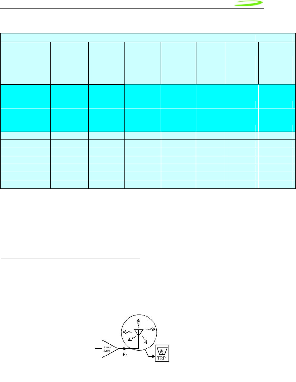
Proprietary & Confidential 68
Novatel Wireless Doc No. OM-01017857 Rev 1
TIS Calculator for Embedded Modules in Jammer Free Environment
Band Technology
Conducted
Sensitivity
Spec
CS Mode1
Conducted
Sensitivity
(dBm)
Cable +
Connector
Loss (dB)
PC
Noise
Rise
over
Thermal
(dB)
Antenna
Efficiency
without
Cable%
Estimated
TIS - Noise
Free
(dBm)
Cellular
824-849 (Tx)
869-894 (Rx) EVDO -104 -108 0 0 100 -108.0
PCS
1850-1910 (Tx)
1930-1990 (Rx) EVDO -104 -108 0 0 100 -108
Band I 2100 WCDMA -106.7 -108 0 0 100 -108
Band II 1900 WCDMA -104.7 -108 0 0 100 -108
Band IV 850 WCDMA -104.7 -108 0 0 100 -108
GSM850 GPRS -99 -108 0 0 100 -108
GSM900 GPRS -99 -108 0 0 100 -108
GSM1800 GPRS -97 -108 0 0 100 -108
GSM1900 GPRS -99 -108 0 0 100 -108
Note 1: TIS is measured in Circuit Switched Mode, do not use Packet Switched values in spreadsheet. Values shown are
not actual Sensitivity values but provided for illustration purposes only.
The EU860D/870D and E725 conducted Sensitivity typical of factory production units will be
made available from Novatel Wireless. Although the data cards operate in Packet switched mode
the values used for estimation are from Circuit Switched mode of operation as this is the mode
the TIS is measured. The results are typically compared against carrier requirements to estimate
compliance margin.
TRP (Total Radiated Power) Requirements
Good radiated performance is critical to the effective operation of a mobile in networks. A
comprehensive characterizing of radiated performance enables carriers to know how well mobiles
work within the specific network design constraints.
Figure 10: Total Radiated Power
to provide a first pass guideline for antenna loss planning. It is not to be a substitute for detailed design activity. Additional
losses, efficiency considerations and other system affects will modify the actual resulting TIS and as such results will
deviate from the TIS calculator shown above. Updates to TIS limits are not controlled in this document.
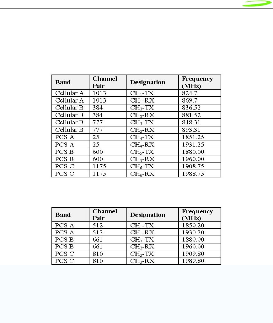
Proprietary & Confidential 69
Novatel Wireless Doc No. OM-01017857 Rev 1
Tests shall be carried out for three different frequency pairs across the bands supported by the
device, as defined for CDMA TIA/EIA-98-D and for GSM 1900 3GPP TS 51.010 in the tables
below.
CDMA Test Frequencies
GSM-1900 Test Frequencies
Radiated power measurements will be recorded in the “free-space” configuration on all applicable
frequencies. For portable units, TPR measurements are repeated on all applicable frequencies.
TPR will be reported using the Figure of Merit for industry analysis. Device power shall comply
with the power levels specified in the relevant industry standards
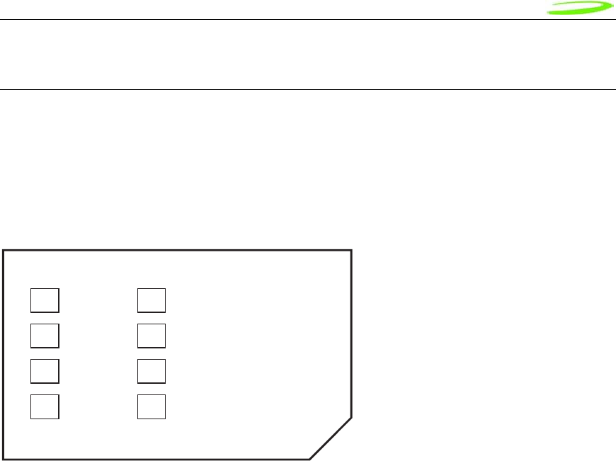
Proprietary & Confidential 70
Novatel Wireless Doc No. OM-01017857 Rev 1
SIM Design Guidelines
Description
The SIM contains subscriber identification, specification and authentication information; and is
required to obtain service. 3.0V and 1.8V SIMs are supported. The physical size and contact
location for the “Plug-in SIM” format is defined in reference [2]. Contact identification is defined in
reference [7]. Electrical characteristics for a 3V SIM are defined in reference [3], and for a 1.8V
SIM in reference [4]. Power sequencing and general protocol operation is defined in reference
[8]. The figure below shows a “Plug-in SIM”.
C1
VCC C5
GND
C2
RST C6
VPP
C3
CLK C7
IO
C4
reserved C8
reserved
Figure 11: Plug-in SIM (shown from contact side)
References
1. 3GPP TS 01.04: "Abbreviations and acronyms"
2. 3GPP TS 11.11: “Specification of the Subscriber Identity Module - Mobile Equipment
(SIM - ME) interface”
3. 3GPP TS 11.12: "Specification of the 3 Volt Subscriber Identity Module - Mobile
Equipment (SIM - ME) interface".
4. 3GPP TS 11.18: “Specification of the 1.8 Volt Subscriber Identity Module - Mobile
Equipment (SIM - ME) interface”
5. 3GPP TS 51.010-1 “Mobile Station (MS) conformance specification; Part 1: Conformance
specification”
6. ISO/IEC 7816-1: “Identification cards – Integrated circuit cards with contacts – Part 1:
Physical characteristics”
7. ISO/IEC 7816-2: “Identification cards – Integrated circuit cards with contacts – Part 2:
Dimensions and locations of the contacts
8. ISO/IEC 7816-3 “Identification cards – Integrated circuit cards with contacts – Part 3:
Electronic signals and transmission protocols”
Operation of SIM interface
For the purposes of this document, the SIM interface is the interface between the SIM and the
laptop at the SIM connector. The ME includes the HSDPA module and laptop SIM circuit.
The SIM interface provides power, clock, reset and data to the SIM. The data is half-duplex (bi-
directional but only able to transfer data in one direction at any time) circuit implemented as an
open-collector signal. When data is transmitted, the ME or the SIM will pull the line to a low
voltage, otherwise the line is pulled up through a resistor. The SIM operates in a
command/response mode where it will only transmit data in response to a received command.
One exception to this is the Answer-To-Reset (ATR) when the SIM transmits data in response to
a reset.

Proprietary & Confidential 71
Novatel Wireless Doc No. OM-01017857 Rev 1
The SIM is interrogated during the boot sequence. First the SIM interface is power sequenced for
1.8 volt operation. If 1.8 volt operation is unsuccessful then the SIM interface is power
sequenced for 3.0 volt operation. Initially a large amount of data is transferred. After this the SIM
is periodically polled to insure it has not been removed.
The following is a high level summary of SIM operation:
1. power cycle at 1.8 volts
2. power cycle at 3.0 volts (if required)
3. SIM transmits ATR
4. ME and SIM exchange data continuously over several seconds
5. ME polls SIM every 25 to 30 seconds
Description of signals
The SIM interface consists of the signals listed in Table 1.
Table 1: SIM interface signals
Name MiniCard pin SIM pin
VCC 8 C1
RST 14 C2
CLK 12 C3
Reserved not connected C4
GND 4, 9, 15, 18, 21, 26, 27, 29, 34, 35, 40, 50 C5
VPP 16 C6
IO 10 C7
Reserved not connected C8
GND
The GND signal is the ground for the ME. All voltages are referenced to this.
VCC
VCC is supplied from the ME by a dedicated regulator. Operation is at 3V and 1.8V.
See Table 2 for a summary of the 3GPP electrical requirements.
Table 2: VCC electrical requirements
Symbol Conditions Minimum Maximum Unit
Vcc 3V operation 2.7 3.3 V
Vcc 1.8V operation 1.62 1.98 V
RST
RST is driven by the ME. A low signal indicates a reset condition.
See Table 3 for a summary of the 3GPP electrical requirements.
Table 3: RST electrical requirements
Symbol Conditions Minimum Maximum Unit
VOH I
OHmax = + 200 µA 0.8 x Vcc Vcc V
VOL I
OLmax = 200 µA 0 0.2 x Vcc V
tR tF 400 µs
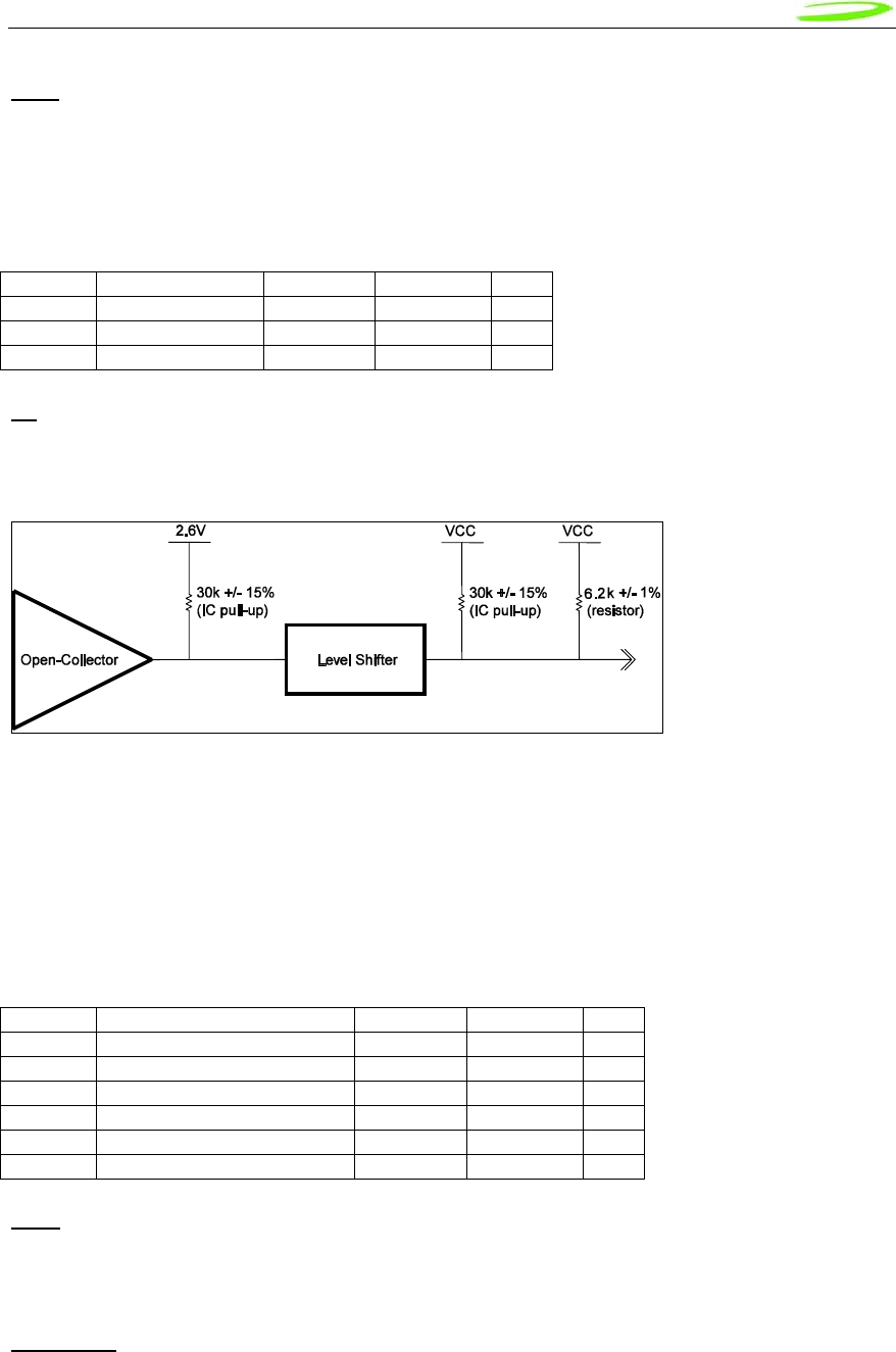
Proprietary & Confidential 72
Novatel Wireless Doc No. OM-01017857 Rev 1
CLK
CLK is driven by the ME. It is the system clock for the SIM. It may be used by the SIM as a
processor clock. The frequency of this signal is from 1 to 4 MHz. The clock is not continuously
running and is stopped in between data transfers.
See Table 4 for a summary of the 3GPP electrical requirements.
Table 4: CLK electrical requirements
Symbol Conditions Minimum Maximum Unit
VOH I
OHmax = + 20 µA 0.7 x Vcc Vcc V
VOL I
OLmax = - 20 µA 0 0.2 x Vcc V
tR tF 50 ns
IO
IO is the bi-directional data signal. The ME may drive this signal low, or may pull it up to VCC.
The SIM may drive this signal low, or it may pull it up to VCC. The pull-up on the HSDPA module
is described in the following figure.
Figure 12: IO driver and pull-ups
The IO signal is much slower than the CLK signal. The default bit time is 372 clock periods.
Each data word is 10 bit times; a start bit, eight (8) data bits, and a parity bit. The data signal
may be direct convention (high voltage is a binary 1, LSB sent first) or inverse convention (low
voltage is a binary 1, MSB sent first) depending on the ATR.
See Table 5 for a summary of the 3GPP electrical requirements.
Table 5: IO electrical requirements
Symbol Conditions Minimum Maximum Unit
VIH I
IHmax = ± 20 µA 0.7 x Vcc Vcc+0.3 V
VIL I
ILmax = + 1 mA - 0.3 0.2 x Vcc V
VOH I
OHmax = + 20 µA 0.7 x Vcc Vcc V
VOL Vcc = 3V, IOLmax = - 1mA 0 0.4 V
VOL Vcc = 1.8V, IOLmax = - 1mA 0 0.3 V
tR tF 1 µs
VPP
VPP is the programming voltage. It is not used and the SIM connector pin should not be
connected. The module pin is not connected.
Reserved
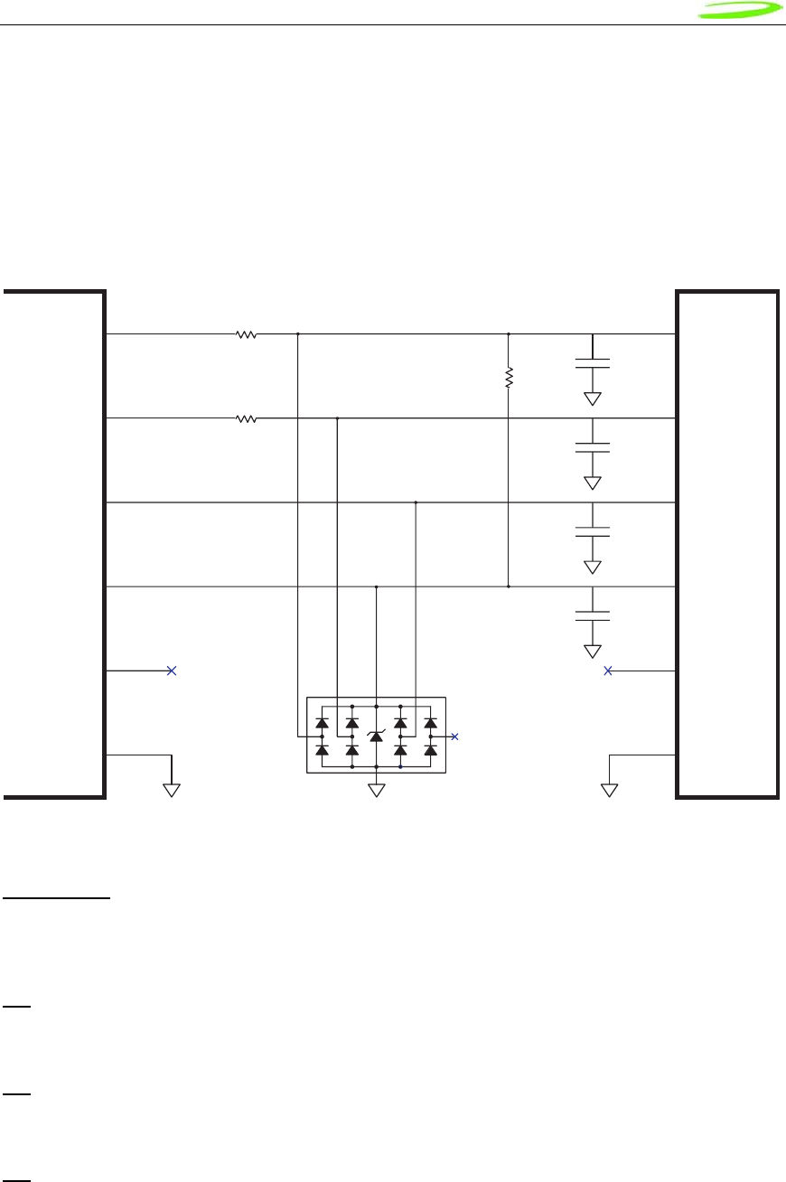
Proprietary & Confidential 73
Novatel Wireless Doc No. OM-01017857 Rev 1
The reserved pins should not be connected on the SIM connector. The SIM connector need not
have contacts at these locations.
Implementation
Refer to the figure below for the recommended circuit.
IO C1
CLK
RST
VCC
VPP
GND
HSDPA
Module
C2
C3
0.1 uF
SIM
Connector
C7
C3
C2
C1
C6
C5
pin 10
pin 12
pin 14
pin 8
pin 16
R1
D1
SRV05-4.TCT
6V
R3
R2
Figure 13: Reference circuit
C1, C2, C3
C1, C2 and C3 are not to be populated. They exist if additional filtering is required. These
components should be placed close to the SIM connector.
R1
R1 should be zero ohms. It exists if additional filtering is required.
R2
R2 should be zero ohms. It exists if additional filtering is required.
R3
R3 should be not be populated. It exists if pull-up adjustments are required.

Proprietary & Confidential 74
Novatel Wireless Doc No. OM-01017857 Rev 1
D1
D1 should be a low capacitance ESD diode array (5 pF or less). It is important to minimize the
capacitance on the IO line. D1 should be placed close to the SIM connector. There is no ESD
protection on the HSDPA module. It is recommended that the ESD protection meet IEC61000-4-
2, level 4 (±15kV air, ±8kV contact).
Signal routing
The CLK line is a high speed digital signal and care must be taken to insure it is isolated from the
other signals. A guard trace between it and the other signals should be used if they are to be
adjacent for any length. A multi-layer PCB with a ground plane should be used. Traces should be
as short as possible. All the SIM interface signals should be routed carefully to avoid being
corrupted by each other or external signals.
IO signal capacitance
The rise time of the IO signal is determined by the total capacitance on the line and the pull-up
resistance. The module has a maximum capacitance of 50 pF and the SIM is considered to have
a maximum capacitance of 30 pF. The laptop capacitance on the IO signal (including
connectors) should be as targeted to be lower than 30 pF. Additional capacitance may be
required to reduce noise, however the IO circuit rise time limit of 1 µs must be considered.
IO signal resistance
The SIM may also have a pull-up on the IO signal, which would have the effect of injecting up to 1
mA into the ME when the ME is transmitting a low level. Series resistance of the IO signal must
be kept very low as the voltage drop across it due to the injected current may cause the output
voltage to rise above the voltage output low specification.
Certification
As the SIM interface is unique to each laptop, each laptop must pass several test cases to obtain
certification. The SIM electrical test cases are specified in section 27.17.2 in reference [5].
The following is a summary of these tests:
• 27.17.2.1.1 Electrical tests on contact C1 (VCC) – Test 1
e.1) The voltage on contact C1 of the SIM/ME interface shall be 3V ± 10 % for Icc up to 6 mA
when the interface is in 3V operation mode.
e.2) The voltage on contact C1 of the SIM/ME interface shall be 1.8V ± 10 % for Icc up to 4
mA when the interface is in 1.8V operation mode.
• 27.17.2.1.2 Electrical tests on contact C1 (VCC) – Test 2
e.1) The voltage on contact C1 of the SIM/ME interface shall be 3V ± 10 % for spikes in the
current consumption with a maximum charge of 12 nAs with no more than 400 ns
duration and an amplitude of at most 60 mA when the interface is in 3V operation mode.
e.2) The voltage on contact C1 of the SIM/ME interface shall be 1.8V ± 10 % for spikes in the
current consumption with a maximum charge of 12 nAs with no more than 400 ns
duration and an amplitude of at most 60 mA when the interface is in 1.8V operation
mode.

Proprietary & Confidential 75
Novatel Wireless Doc No. OM-01017857 Rev 1
The following current spikes are applied (The specified spike durations are measured at 50 %
of the spike amplitude):
1) continuous spikes:
current amplitude 12 mA
current offset 0 mA
Duration 100 ns
Pause 100 ns
2) continuous spikes:
current 12 mA
current offset 0 mA
Duration 400 ns
Pause 400 ns
3) continuous spikes:
current amplitude 9 mA
current offset 3 mA
(i.e. maximum amplitude = 3 mA + 9 mA = 12 mA
Duration 150 ns
Pause 300 ns
4) random spikes:
current amplitude 60 mA
current offset 0 mA
Duration 200 ns
Pause between 0.1 ms and 500 ms, randomly varied
5) random spikes:
current amplitude 30 mA
current offset 0 mA
Duration 400 ns
Pause between 0.1 ms and 500 ms, randomly varied
6) random spikes
current amplitude 57 mA
current offset 3 mA
(i.e. maximum amplitude = 3 mA + 57 mA = 60 mA
Duration 200 ns
Pause between 0.1 ms and 500 ms, randomly varied
• 27.17.2.2 Electrical tests on contact C2 (RST)
e.1) The voltage on contact C2 (RST) of the SIM/ME interface shall be between 0.3V and
+0.7V for a current of 200 µA in low state and between 2.15 V and Vcc + 0.3V for a
current of +200 µA in high state when the interface is in 3V operation mode.
e.2) The voltage on contact C2 (RST) of the SIM/ME interface shall be between 0.3V and
+0.47V for a current of 200 µA in low state and between 1.3 V and Vcc + 0.3V for a
current of +200 µA in high state when the interface is in 1.8V operation mode.
• 27.17.2.3 Electrical tests on contact C3 (CLK)

Proprietary & Confidential 76
Novatel Wireless Doc No. OM-01017857 Rev 1
e.1) The voltage on contact C3 (CLK) of the SIM/ME interface shall be between 0.3V and
+0.47V for a current of 20 µA in low state and between 1.21V and Vcc +0.3V for a
current of +20 µA in high state when the interface is in 1.8V operation mode.
e.2) The rise and the fall time of the clock signal shall not exceed 50 ns when the interface is
in 1.8V operation mode.
e.3) The cycle ratio of the clock signal shall be between 40 % and 60 % of the period, in
steady state when the interface is in 1.8V operation mode.
e.4) The frequency of the clock signal shall be between 1 MHz and 4 MHz when the interface
is in 1.8V operation mode.
e.5) The voltage on contact C3 (CLK) of the SIM/ME interface shall be between 0.3V and
+0.6V for a current of 20 µA in low state and between 1.9V and Vcc +0.3V for a current
of +20 µA in high state when the interface is in 3V operation mode.
e.6) The rise and the fall time of the clock signal shall not exceed 50 ns when the interface is
in 3V operation mode.
e.7) The cycle ratio of the clock signal shall be between 40 % and 60 % of the period, in
steady state when the interface is in 3V operation mode.
e.8) The frequency of the clock signal shall be between 1 MHz and 4 MHz when the interface
is in 3V operation mode.
• 27.17.2.5 Electrical tests on contact C7 (IO)
e.1) ME receiving state A (low state):
With an imposed voltage of 0V the current flowing out of the ME shall not exceed 1 mA
when the ME is in 3V operation mode.
e.2) ME transmitting state A (low state):
The voltage shall be between 0.3V and 0.4V when a current of 1 mA flowing into the ME
is applied when the ME is in 3V operation mode.
e.3) ME transmitting or receiving state Z (high state):
The voltage shall be between 0.7*Vcc and Vcc + 0.3V when a current of 20 µA flowing
out of the ME is applied when the ME is in 3V operation mode.
e.4) The rise time and the fall time of the I/O signal shall not exceed 1 µs when the ME is in
3V operation mode.
e.5) ME receiving state A (low state):
With an imposed voltage of 0V the current flowing out of the ME shall not exceed 1 mA
when the ME is in 1.8V operation mode.
e.6) ME transmitting state A (low state):
The voltage shall be between 0.3V and 0.3V when a current of 1 mA flowing into the ME
is applied when the ME is in 1.8V operation mode.
e.7) ME transmitting or receiving state Z (high state):
The voltage shall be between 0.7*Vcc and Vcc + 0.3V when a current of 20 µA flowing
out of the ME is applied when the ME is in 1.8V operation mode.
e.8) The rise time and the fall time of the I/O signal shall not exceed 1 µs when the ME is in
1.8V operation mode.

Proprietary & Confidential 77
Novatel Wireless Doc No. OM-01017857 Rev 1
SM Bus Design Guidelines
Introduction
This section will describe the SMBus interface parameters ensuring interoperability with Novatel’s
PCI Express Mini Cards the SM Bus interface.
The SMBus is a two-wire interface through which various system components can communicate
with each other and the rest of the system. It is based on the principles of operation of I2C. See
the PCI Express Card Electromechanical Specification for more details on the functional
requirements for the SMBus.
The SMB_CLK signal and the SMB_DAT signal are available on pins 30 and 32 of the PCI
Express Mini connector.
This interface will support a subset of the specification as detailed in this section.
SMBus is an i2c based protocol that will drive a slave device and report various data regarding
mobile status or real-time e-mail to it, in accordance to the SMBus protocol specification. It is
important to note that the EU860D/EU870D & E725 PCI Express Mini-card acts as a bus
master and not as a slave.
I2C Controller
The controller is an I2C-compliant, master-only device. The controller can access all available I2C
slaves on the bus, but cannot be accessed by any other masters on the bus.
Both SDA and SCL are bi-directional lines, connected to a positive supply voltage via a current-
source or pull-up resistor. When the bus is free, both lines are HIGH. The output stages of
devices connected to the bus must have an open-drain or open-collector to perform the wired-
AND function.
A simplified version of the I2C bus operation is as follows:
• The master generates a START condition, signaling all ICs on the bus to listen for data.
• The master writes a 7-bit address, followed by a read/write bit to select the device as a
transmitter or receiver.
• The receiver sends an acknowledge bit over the bus. The transmitter must read this bit to
determine whether or not the addressed device is on the bus.
• Depending on the value of the read/write bit, any number of 8-bit messages can be
transmitted or received by the master. These messages are specific to the I2C device
used. After 8 message bits are written to the bus, the transmitter will receive an
acknowledge bit. This message and acknowledge transfer continues until the entire
message is transmitted.
• The message is terminated by the master with a STOP condition. This frees the bus for
the next master to begin communications.
• Data on the I2C-bus can be transferred at rates of up to 100 kbps in the Standard-mode,
• The number of interfaces connected to the bus is solely dependent on the bus
capacitance limit of 400 pF.

Proprietary & Confidential 78
Novatel Wireless Doc No. OM-01017857 Rev 1
HW Parameters
The System Management Bus (SMBus) is a two-wire interface through which various system
component chips can communicate with each other and with the rest of the system. It is based on
the principles of operation of I 2 C.
The reader is referred to SMBus reference as described in the System Management Bus
(SMBus) Specification, Version 2.0 for further details on its operation.
The peripheral board communicating to the SMBus must provide pull-ups to 2.6V. It is
recommended that a 2.7 K ohm pull connected to 2.6 Volt rail.
DC parameters
Symbol Parameter Limits Units
Min Max
VIL Data, Clock Input Low Voltage - 0.3 0.86 V
VIH Data, Clock Input High Voltage 1.78 2.77 V
VOL Data, Clock Output Low Voltage 0 0.45 V
ILEAK Input Leakage - - ±5 µA
VDD Nominal bus voltage 2.47 2.73 V
Table 2: SMBus DC specification
SM Bus interface Board
Pull up resistors on both lines (SMB_CLK and SMB_DATA) and solid ground connections are
necessary. Without proper pull up values and good ground and instability in communication will
be experienced.
As illustrated below it is recommended that a 2.7 K ohm pull connected to 2.6 Volt rail.
Figure 14: SM Pull-up Configuration
Host Board Novatel PCI Express Mini Card
Host Board Novatel PCI Express Mini Card
GPIO
2.6 V
2.7K
Peripheral
(Slave)
SMB_CLK Pin (32)
EU8X0/E725
SMB_DATA Pin (30)
GPIO
2.6 V EU8X0/E725
2.7K
Peripheral
(Slave)

Proprietary & Confidential 79
Novatel Wireless Doc No. OM-01017857 Rev 1
MobiLink Connection Manager
Overview
The Novatel Wireless MobiLink™ Communications Software Suite is a family of wireless
connectivity applications that connect mobile devices using wireless wide area networks (WWAN)
as well as WiFi and Ethernet in a single application to allow quick and easy access to email, the
Internet and corporate networks anytime, anywhere. With MobiLink and a wide area wireless
device, mobile users can stay productive and connected to customers and colleagues while out of
the office. MobiLink is optimally engineered to work with all of Novatel Wireless' Wireless
Modems for best in class 3G wireless broadband access solutions.
The MobiLink Communications Software Suite of applications contains a messaging Client that
manages 2 way SMS operations, an address book Client that manages contacts and phone
number, connection manager that manages the connectivity, and a customization utility to
manage and generate install customization settings. The following section will detail the features
of each application.
Purpose
This section provides high level user interface information regarding the appearance and
operation of the MobiLink™ Connection Manager application developed for Windows 2000, XP
Pro, and XP Home.
Applicable Documents
All software names and version numbers displayed should meet the requirements outlined in the
Consistency & Naming Conventions Requirements Document. This document also covers
the requirements for the desktop, including the necessary icons and the use of the Start menu.
For more details on meeting the requirements for Microsoft™ Windows certification, refer to the
document entitled, Application Specification for Microsoft™ Windows 2000 and Windows
XP for Desktop Applications, which can be found on Microsoft™’s web site.
GENERAL FEATURES
User Interface Functionality
The first design principle for MobiLink applications is that the basic information and controls
needed for day-to-day operations are quickly and easily accessible while less frequently used
functions are located deeper in the menu system. The user interface is designed to be intuitive to
use and will not require a large learning curve for the average user. The second design principle
for MobiLink is to be easily customizable in order to be able to meet the various requirements of a
global market.
Layout
The general layout of the main windows is designed to display important information for
connectivity while making it easy to navigate to other functions. The main function such as mobile
status and signal strength display is shown in the main window. The connection button is
prominently displayed and easily accessible. The main MobiLink display is shown below.
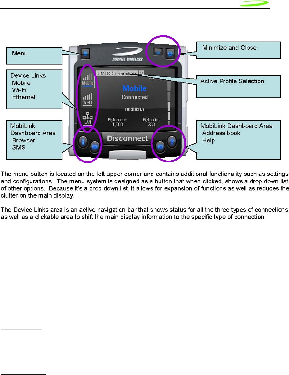
Proprietary & Confidential 80
Novatel Wireless Doc No. OM-01017857 Rev 1
Figure 15: Main MobiLink Display
The Dashboard Area in the layout is designed as a launching area for other applications. The
default applications in the current design are internet browser, SMS Client, Addressbook, and
Help file. Other applications can be launched.
The Active Profile Selection is a list that allows for easy access to choose the active profile to use
for connection. For 3G, this list is a list of connection profiles while for WiFi, this is a list of access
points found. For WiFi, this list also shows the signal quality and whether the access point is
encrypted.
Lastly, there are the standard minimize and close buttons that are the main stay of any
application. The minimize button hides the application as a tray icon and the close button
gracefully closes the application.
Mouse Over
Mouse over is a feature of the application that displays helpful hint about the function of the
application as the mouse is moved over an active area of the application such as the menu
button.
Snap to Edge
Snap to edge is a feature that makes the MobiLink application window snap to the sides of the
Windows desktop as the user drags the application close to the edge.
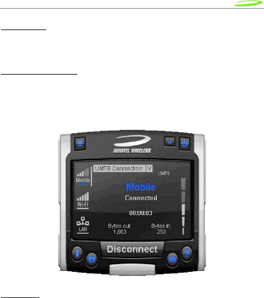
Proprietary & Confidential 81
Novatel Wireless Doc No. OM-01017857 Rev 1
Hot Swapping
The design of MobiLink allows for hot swapping of the 3G device. Users can plug and unplug a
3G wireless device and MobiLink will automatically recognize the technology and dynamically
change the display to show the relevant information.
Skinning Customization
Due to the software design and the underlying graphics engine used, the main “skin” of MobiLink
is completely customizable. The skin is contained in separate resource files that can be easily
changed for branding or function. One design is shown below and more can be developed.
Figure 16: Skin Design
Localization
It is the intent of the MobiLink™ connection manager design to be able to support localization.
Double byte Unicode is used and all the text used by MobiLink is kept in resource files that can
easily be translated and added. Currently MobiLink supports the following languages:
• Chinese Simplified
• Chinese Traditional
• Danish
• English
• French
• German
• Italian
• Spanish
• Swedish
• Polish
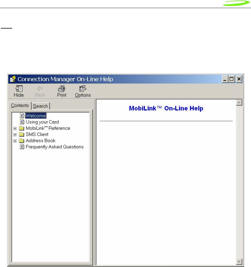
Proprietary & Confidential 82
Novatel Wireless Doc No. OM-01017857 Rev 1
File
The MobiLink™ connection manager shall contain a help file that can be accessed through a help
button or via F1 key. The help file is also localizable and is in HTML format as shown below:
Figure 17: On-Line Help
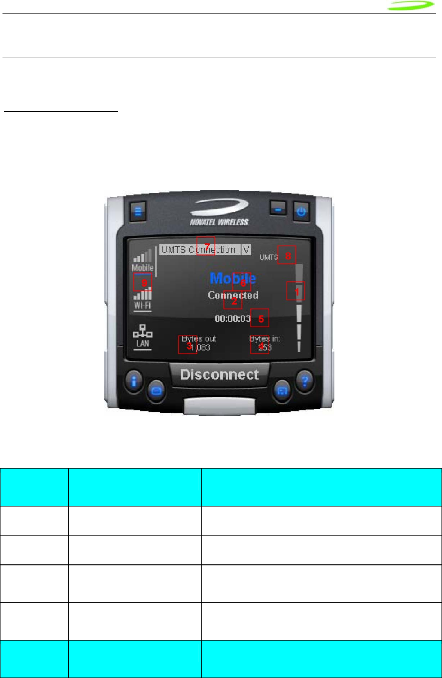
Proprietary & Confidential 83
Novatel Wireless Doc No. OM-01017857 Rev 1
MOBILINK™ FEATURES
The following sections describe the various features of MobiLink.
Main Display Window
The main display area of MobiLink is used for status indication of the different types of
connections. The following information is displayed.
Figure 18: Status Indication
Status Indication
Number
Reference Status Information Description
1 Signal Strength Bar This is the quality of the signal for the selected
2 Connection Status This is a text indicating the connection status
3 Connect Duration This indicates the number of hours, minutes, and
seconds the current connection has been up
4 Bytes Out/Packets Out This indicates the number of bytes sent for the
current connection
Number
Reference Status Information Description

Proprietary & Confidential 84
Novatel Wireless Doc No. OM-01017857 Rev 1
5 Bytes In/Packet In This indicates the number of bytes received for the
current connection
6 Network Name For UMTS/HSDPA, this would show the network
name received from the AT+COPS command
7 Profile List This is the list of supported profiles that contains the
connection settings such as username and
password and QoS for 3G. This is a list of the 3G
profiles for the 3G networks and a list of WiFi
profiles for the WiFi network. The displayed profile is
the active profile.
8 Indicators The indicators are icons that show additional status
of the 3G wireless. Each indicator will be described
below.
9 Connection Type Selection
Bar This is a navigation bar that selects which
connection information is displayed in the main
window. As the connection is selected, the main
window will slide to show the right information. Each
of the connection icons for this navigation bar also
shows the signal strength of the respective
connection.
The connection navigation bar was added to support the universal connection management
functionality. By having a navigation bar, the user is presented with just the information that is
required for the connection of interest. The pictures below show the three views for each
connection type.
Figure 19: 3G Wireless View
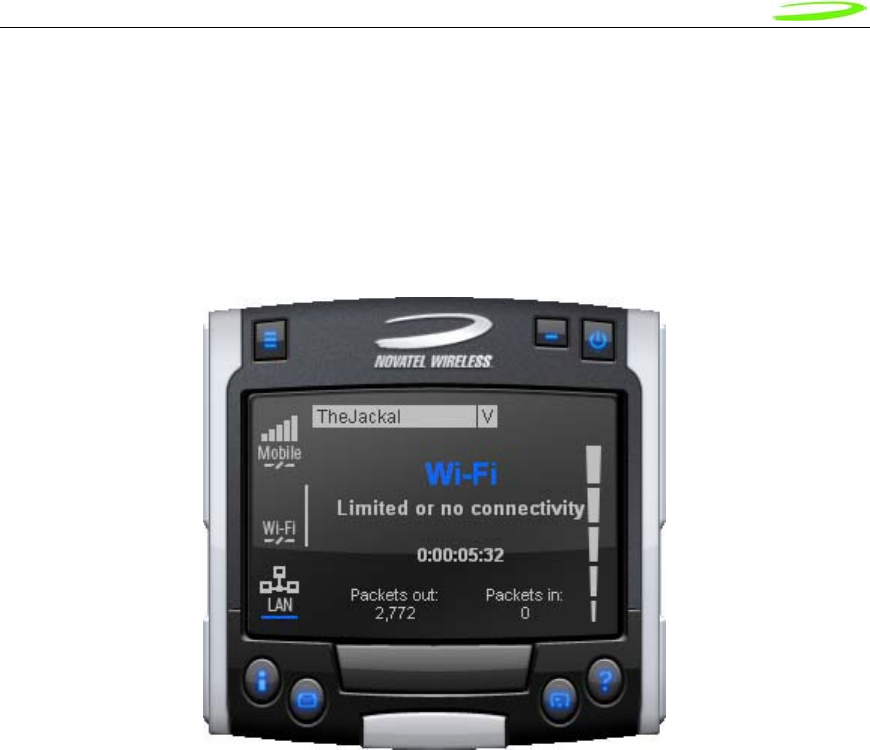
Proprietary & Confidential 85
Novatel Wireless Doc No. OM-01017857 Rev 1
With the 3G Wireless view, connection button can be used to connect to the chosen profile
displayed. The status icons for 3G will be displayed on the top right corner and when connected,
byte count and time displayed will be shown. The vertical bar next to the navigation bar indicates
which view is currently active. When the user clicks on the WiFi navigation button, the WiFi view
will be shown.
Figure 20: WiFi View
The WiFi view does not have a connection button since WiFi is a connectionless adaptor. The
view does show signal strength, packet count, and connection time as well as connection status.
Since MobiLink’s WiFi is developed using Windows zero configuration, MobiLink WiFi control can
coexist with Windows wireless network connection. The default hotspot is shown in the selection
list in the same place as the 3G profile list. The list of hotspots is dynamically generated based on
a WiFi network scan of the area. Users can chose to make another hotspot active by clicking on
the selection list shown below.
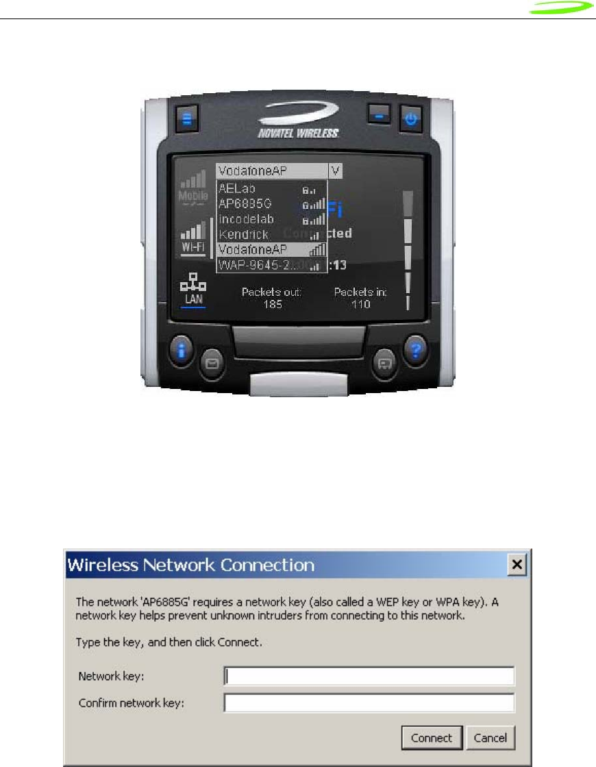
Proprietary & Confidential 86
Novatel Wireless Doc No. OM-01017857 Rev 1
Figure 21: HotSpot Activation
The connection list displays all the available hotspots seen by the WiFi adaptor. The list is
arranged in alphabetical order and the signal level for each is shown on the side. Also, if the
hotspot is WEP protected, a lock icon will be shown. To change hotspot, users can select one
from the list. If the hotspot is WEP protected the following dialog will be displayed to query for the
network key.
Figure 22: Network Connection
Lastly, the user can view the Ethernet connection by clicking on the Ethernet navigation bar icon.
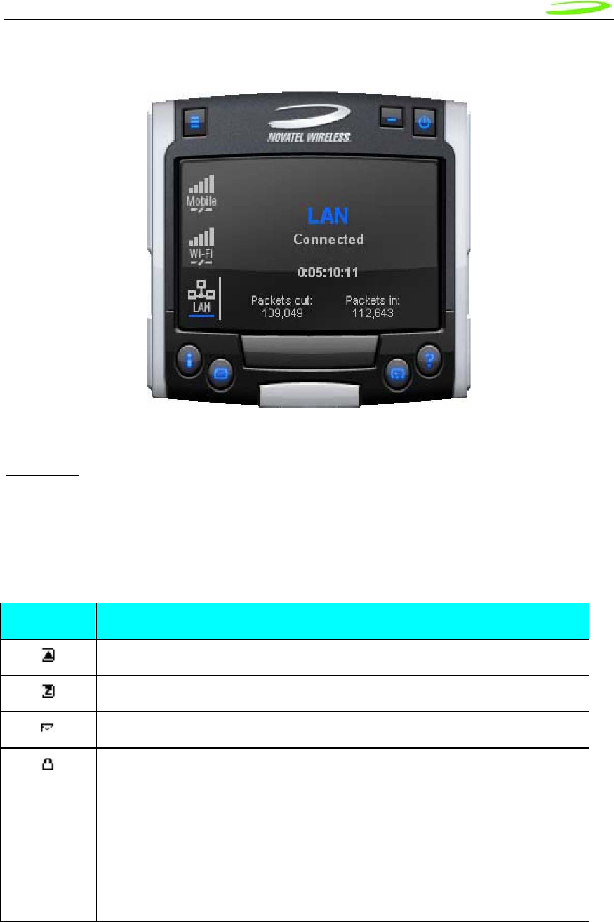
Proprietary & Confidential 87
Novatel Wireless Doc No. OM-01017857 Rev 1
Figure 23: Ethernet View
The Ethernet view shows the connection status, the packet count, and the connection duration.
Indicators
3G indicators are shown on the right upper corner of the main status display. The design of these
indicators is based on standard 3G indicators used on mobile devices. The following table
describes all the indicators.
3G Indicators
Indicator Status/Description
3G radio is roaming
3G in dormant mode (May not be applicable for all MAs)
New SMS is available
3G device is locked
WWAN
Network This is the type of WWAN protocol that is acquired. The types are:
• HSDPA • UMTS
• GPRS • GSM
• IS95a • 1XRTT
• EVDO
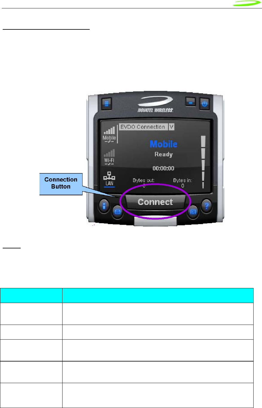
Proprietary & Confidential 88
Novatel Wireless Doc No. OM-01017857 Rev 1
Connect/Disconnect Button
Since the main purpose of MobiLink’s connection manager is for connecting the user to the
internet, the connection button is prominently placed. The Connection button is used to initiate a
3G data connection. The connection button is not used for WiFi or Ethernet since the network
adaptors are connectionless and will automatically connect as long as there is a valid connection.
Figure 24: Connection Button
Menu
When the Menu button is clicked, the following menu subjects are displayed:
Menu Subjects
Menu Item Description
Profile Manager This menu item opens up the dialog for creating, editing, and deleting
profiles
Configuration This menu item opens up a dialog for changing MobiLink settings
Properties This menu item opens up a dialog that displays the properties of the
3G modem
Report This menu item opens up a dialog that displays the connections
statistics and connection history
Transparency This menu item is to set the application display transparency. This
feature allows the desktop items below the application to be shown
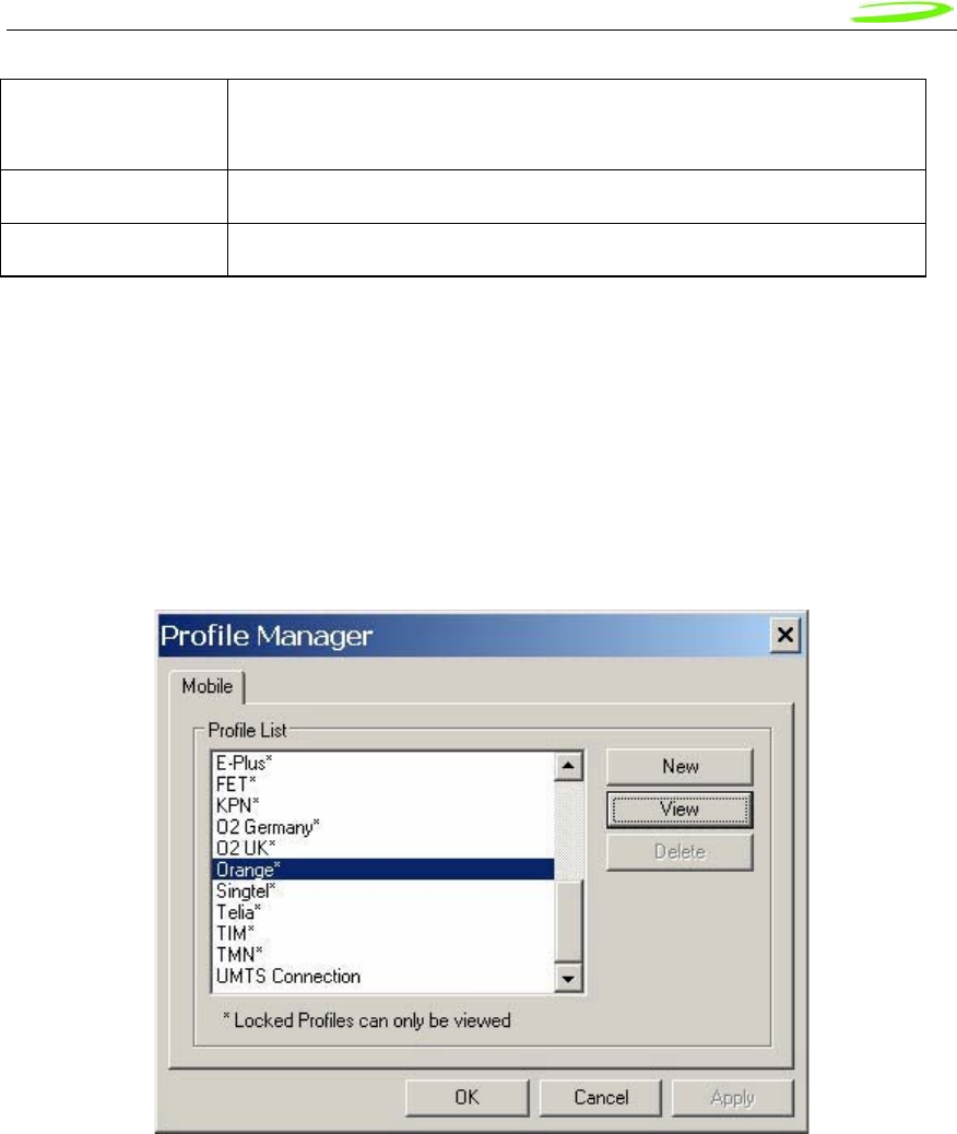
Proprietary & Confidential 89
Novatel Wireless Doc No. OM-01017857 Rev 1
through the transparency
About This menu item brings up information about the MobiLink application
Exit This menu item will quit the MobiLink application
Profile Manager
The profile manager allows the user to manage the connection profiles for both the 3G
connection and WiFi connection. The user can create a profile using the New, edit or view the
profile, and delete a profile.
3G Wireless Profiles
The first tab shows the 3G wireless profiles as shown below.
Figure 25: 3G Profiles
The wireless profiles can be selected for viewing in the case of a locked profile and for editing in
the case of an unlocked profile. Locked profiles are preset and can not be deleted or altered.
This is to reduce the incidence of connection problems related to incorrect settings due to user
error. The dialog below shows the actual profile settings. For locked profiles, the settings are
grayed out and cannot be modified.
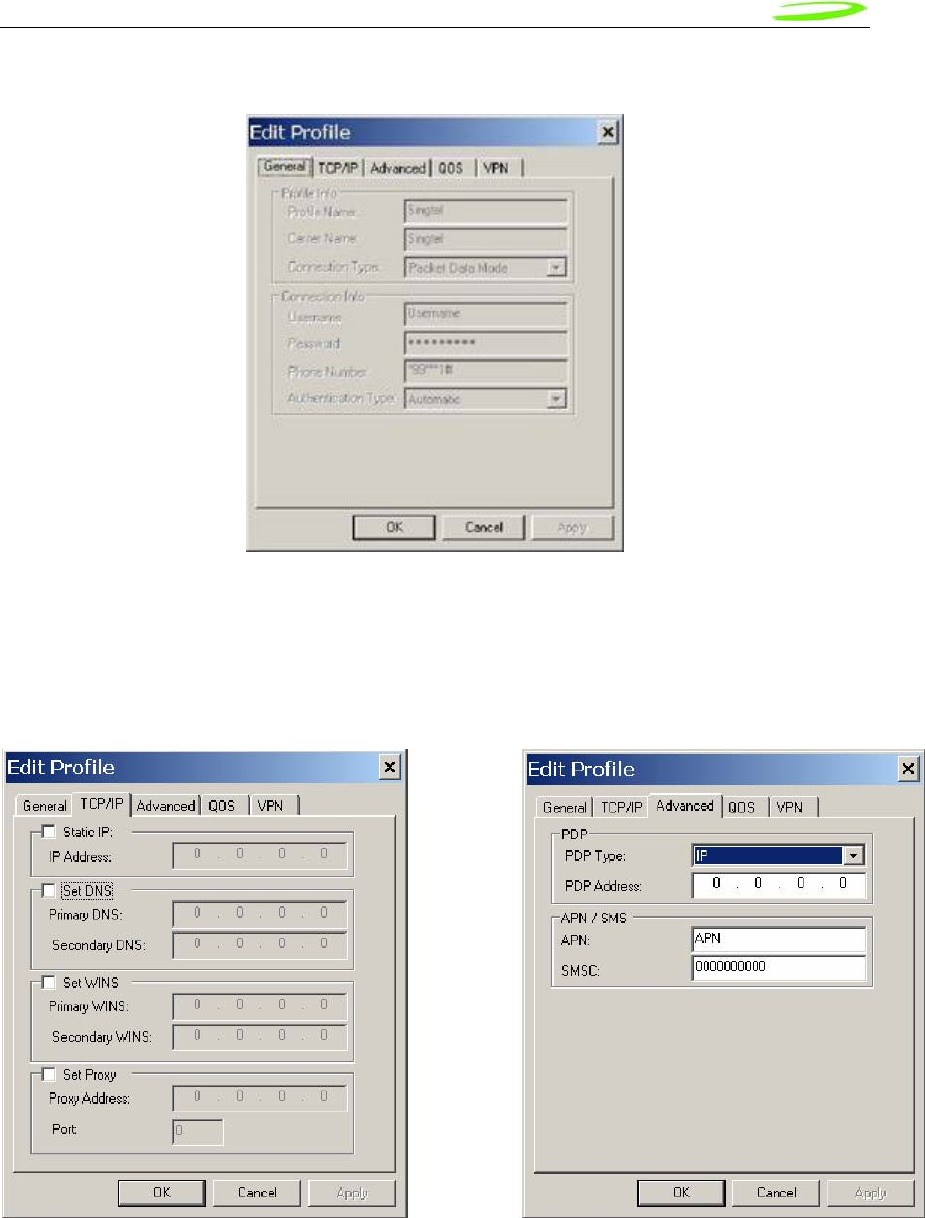
Proprietary & Confidential 90
Novatel Wireless Doc No. OM-01017857 Rev 1
Figure 26: Profile Settings
The profile settings are categorized under different tabs and can be different for UMTS and
CDMA. In the case of CDMA, the QoS tab does not apply. The following screens show the
various settings under each tab.
Figure 27: Different Tab Settngs
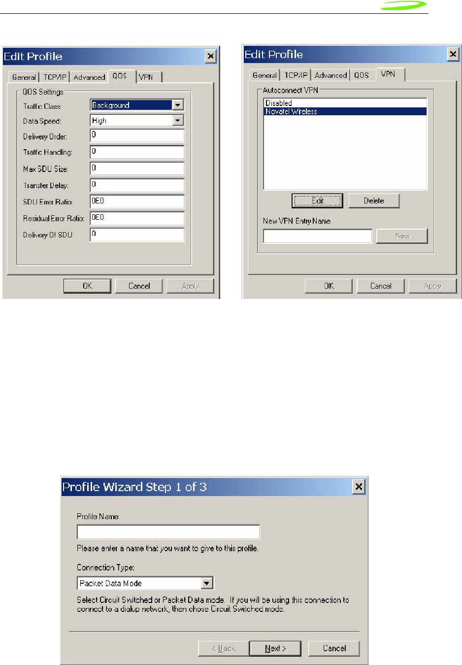
Proprietary & Confidential 91
Novatel Wireless Doc No. OM-01017857 Rev 1
When changes are made to any of the tabs, the user must click the Apply button to effect the
changes. Cancel can be clicked to cancel the settings. The exception is the on the last VPN tab.
When creating a new VPN, the VPN entry is created when the user clicks the New button with an
entry name. The apply button is used to change the associated VPN for the profile. VPN
association is used to automatically establish a VPN session after a successful 3G connection.
When creating a profile by clicking on the New button, the profile wizard is used to guide the user
through some simple steps for creating a new profile. The advanced settings are preset based on
a template profile for the carrier network and hidden from the user. In the rare case where
advanced parameters need to be changed, the user can then select the newly created profile and
click on Edit to edit the parameters.
Figure 28: Profile Wizard Step 1
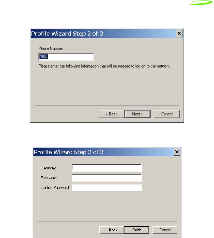
Proprietary & Confidential 92
Novatel Wireless Doc No. OM-01017857 Rev 1
Figure 29: Profile Wizard Step #2
Figure 30: Profile Wizard Step #3
WiFi Profiles
TBD
Configuration
The configuration menu has all the available settings for MobiLink. The configuration window is
broken down in to four functional tabs. The General tab is for the user interface settings and
language selection. The Mobile tab is used to set parameters for the 3G device. The WiFi tab
has settings for WiFi adaptor, and the Ethernet tab is used to set the Ethernet adaptor. Each of
the tabs is shown below.
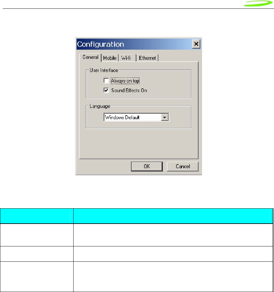
Proprietary & Confidential 93
Novatel Wireless Doc No. OM-01017857 Rev 1
Figure 31: General Tab
General Tab Features
General Tab Feature Description
Always on top When checked, the application is always the top most application on
the desktop
Sound Effects On When checked, sounds will be played on user actions
Language This is a selection list for choosing the language to be used for
MobiLink. Windows Default will base the language on what Windows
uses as the native language
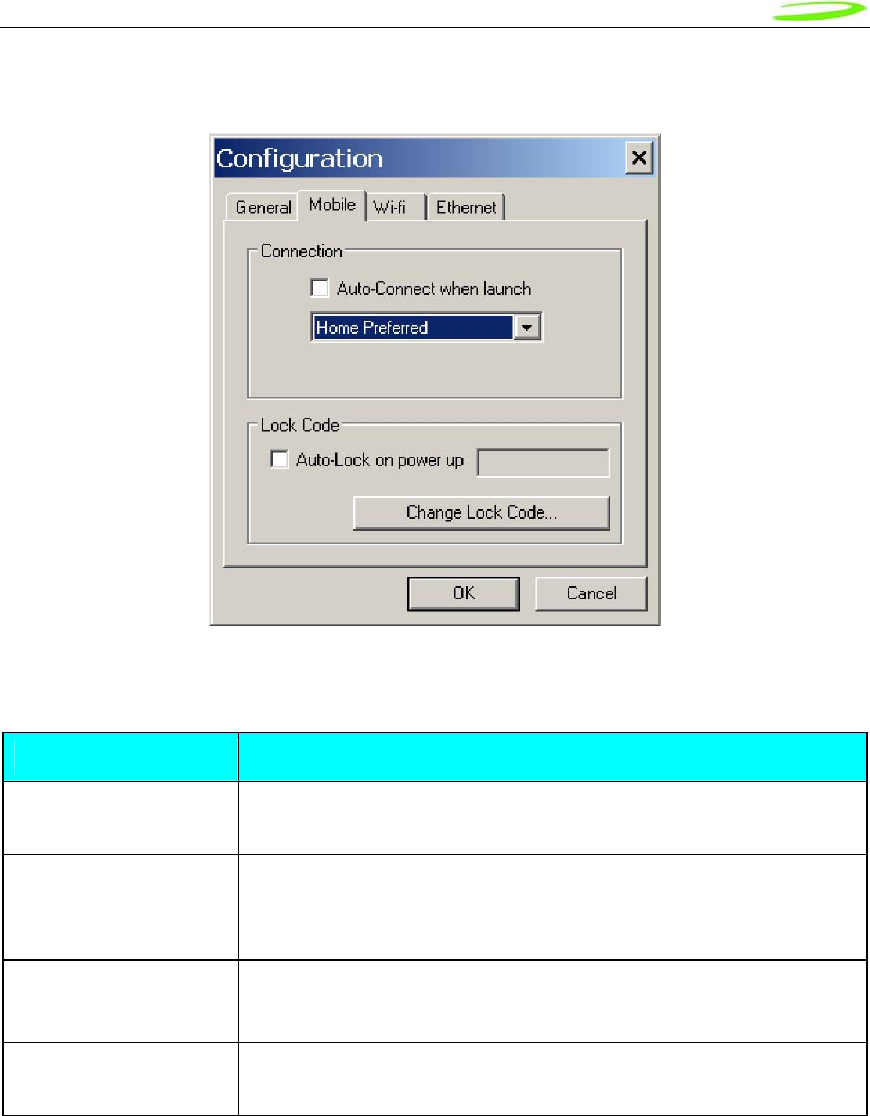
Proprietary & Confidential 94
Novatel Wireless Doc No. OM-01017857 Rev 1
Figure 32: Mobile Tab
Mobile Tab Features
Feature Description
Auto-Connect when
launch This feature is for MobiLink to automatically connect to the network
when launched
Network Selection This selection is used to select the network preference. For CDMA,
this is to select the operating network and for UMTS/HSDPA, it’s for
selecting the radio access technology
Auto-Lock on power up Check to lock the SIM upon power up. A 4 to 8 digits code must be
supplied to turn on and off the auto lock feature.
Change Lock Code Chick this button to change the lock code. This button is only active
if the auto-lock SIM feature is turned on.
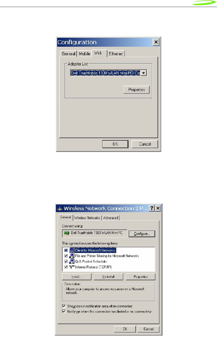
Proprietary & Confidential 95
Novatel Wireless Doc No. OM-01017857 Rev 1
Figure 33: WiFi Tab
The WiFi tab allows user to choose the WiFi adaptor from a list of detected adaptors. Also, the
adaptor properties can be modified by clicking on the properties button. The wireless adaptor
properties window is shown below.
Figure 34: WAP Window
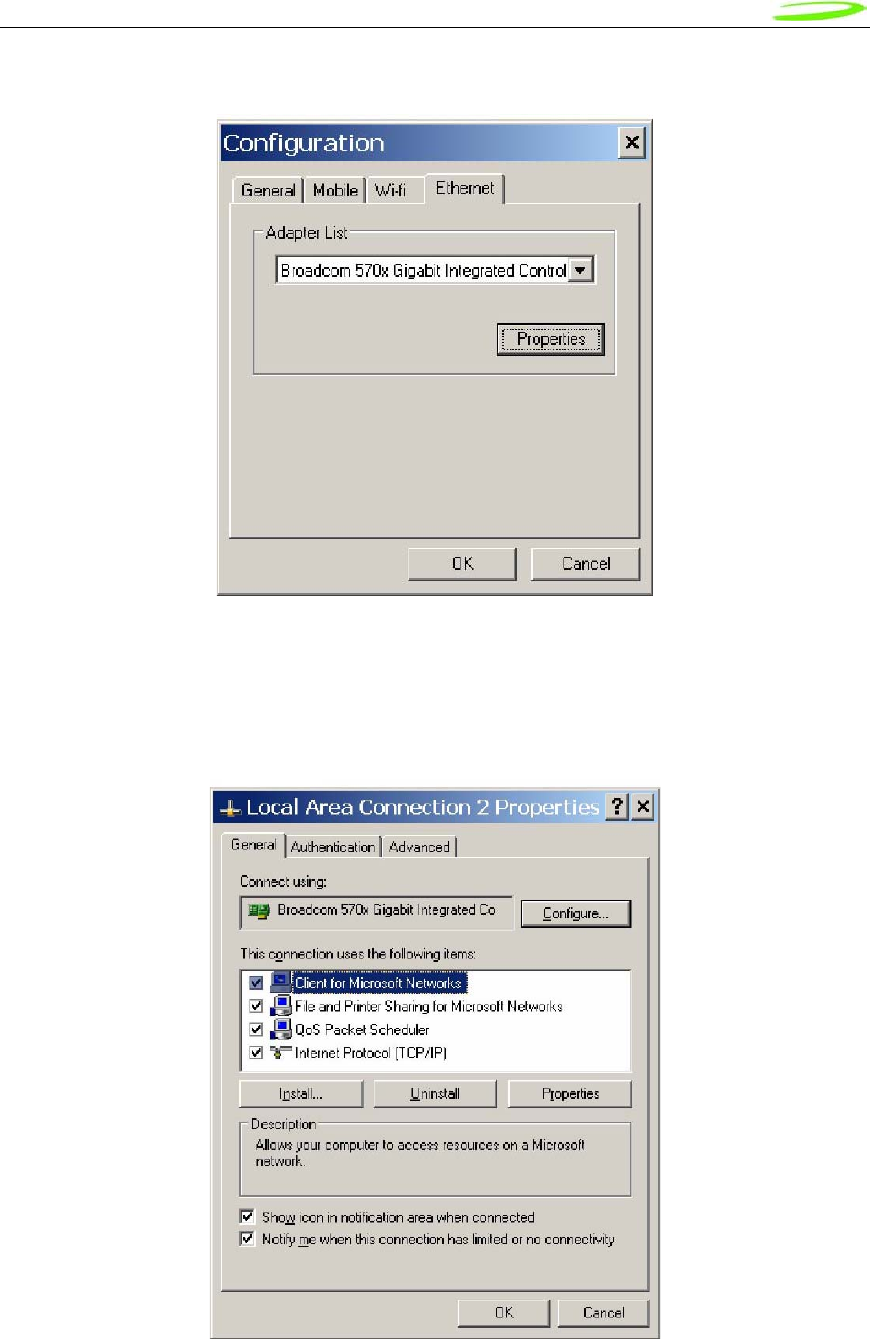
Proprietary & Confidential 96
Novatel Wireless Doc No. OM-01017857 Rev 1
Figure 35: Ethernet Tab
The Ethernet tab allows user to choose the Ethernet adaptor from a list of detected adaptors.
Also, the adaptor properties can be modified by clicking on the properties button. The adaptor
properties window is shown below.
Figure 36: AP Window
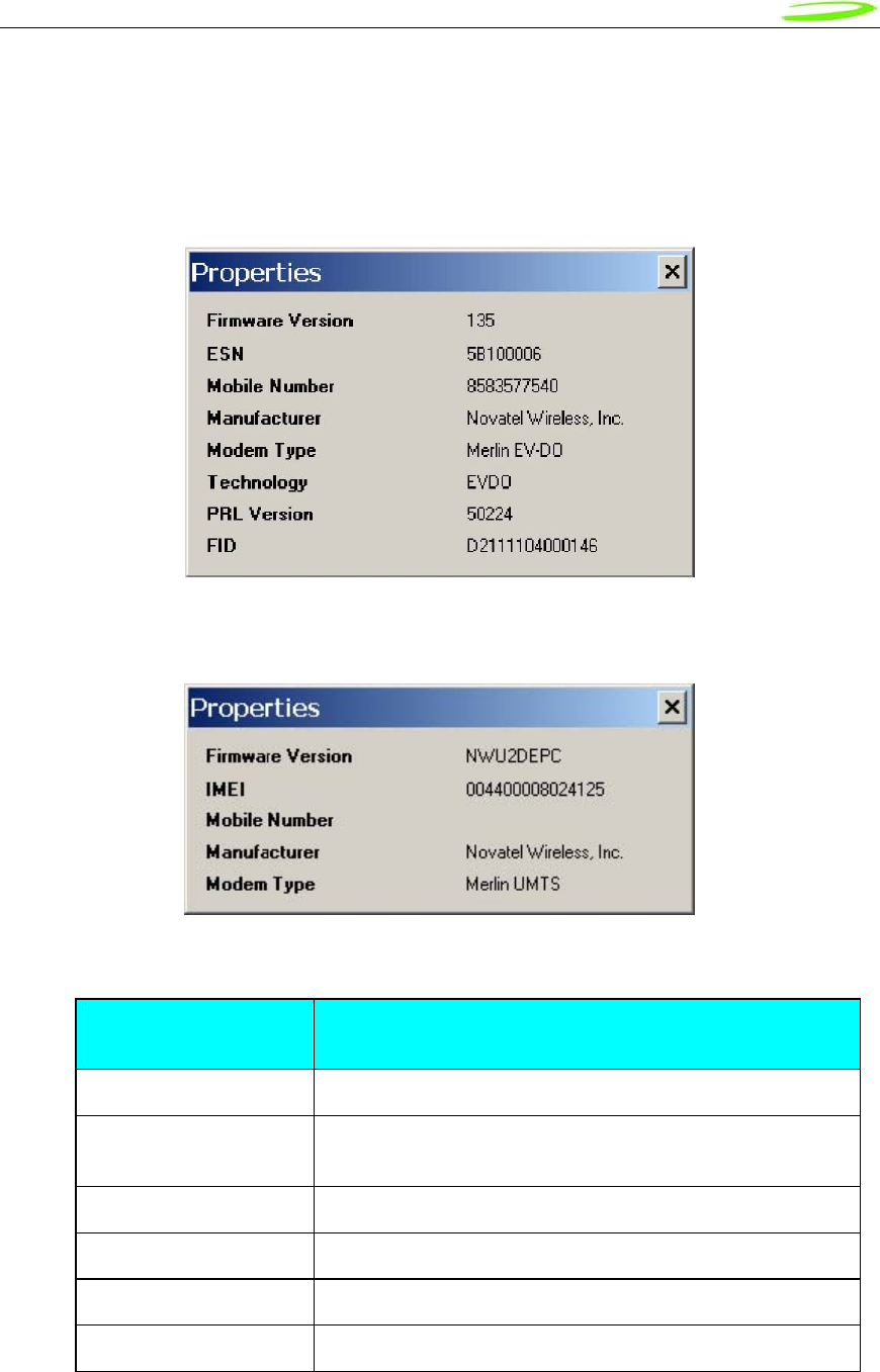
Proprietary & Confidential 97
Novatel Wireless Doc No. OM-01017857 Rev 1
Properties Menu
The properties menu displays some of the key properties of the UMTS and EVDO devices.
Figure 37: CDMA
Figure 38: UMTS/HSDPA
Identity Properties
Property Description
Firmware Version Firmware version of the 3G device
IMEI/ESN International Mobile Equipment Identity (UMTS)/ Electronic
Serial Number (CDMA)
Mobil Number Number for the mobile
Manufacturer Who produced the modem
Modem Type Modem technology
Technology 3G technology
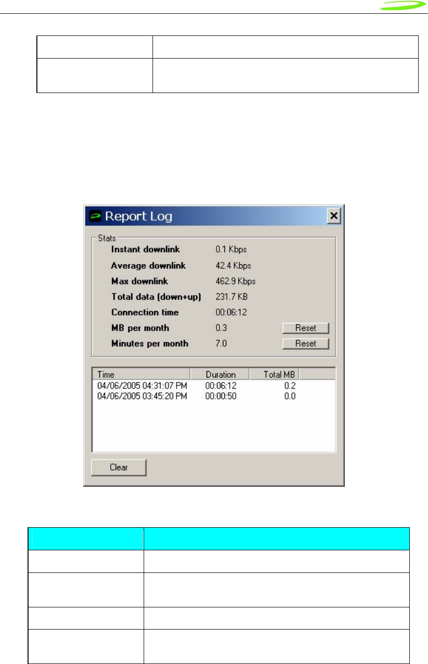
Proprietary & Confidential 98
Novatel Wireless Doc No. OM-01017857 Rev 1
PRL version Preferred Roaming List version number(CDMA)
FID Factory ID. This is a unique tracking number for factory
builds
Report Log
The report log has statistic information about the current connection as well as a history list of
past connections.
Figure 39: Report Log
Report Values
Value Description
Instant downlink This is most recent measured downlink throughput
Average downlink This is the average of all the measured downlink
throughput
Max downlink This is the maximum achieved downlink throughput
Total data This is the total data that has been ever sent since
MobiLink has been installed on the machine
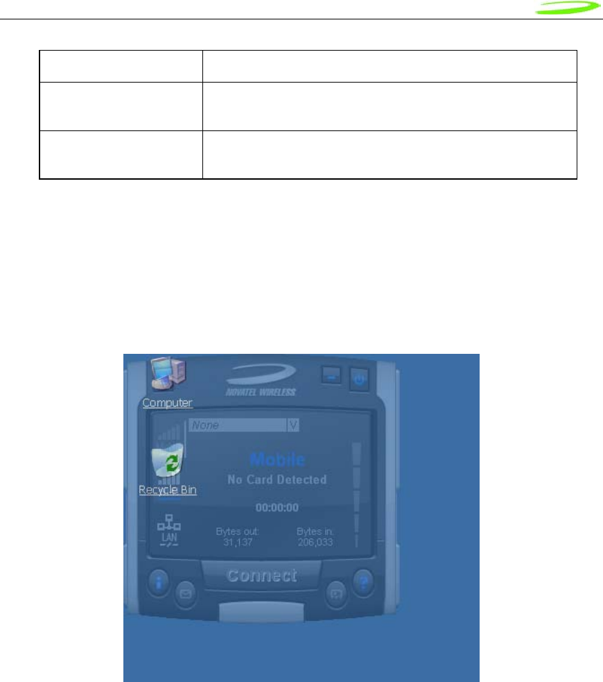
Proprietary & Confidential 99
Novatel Wireless Doc No. OM-01017857 Rev 1
Connection time The is the amount of time the connection has lasted
MB per month This is a resettable counter of how many bytes since the
last reset
Minutes per month This is a resettable counter of how many minutes since the
last reset
Transparency
This menu feature allows the user to select the percent transparency for MobiLink. The choices
range from 0% to 90% with 0% being solid and 90% being very transparent. Transparency
allows desktop items below MobiLink to be displayed for better multitasking. Below is an
example of MobiLink transparency on a desktop.
Figure 40: Desktop Transparency
About
The About dialog displays MobiLink information such as version number, release date, and
copyright.
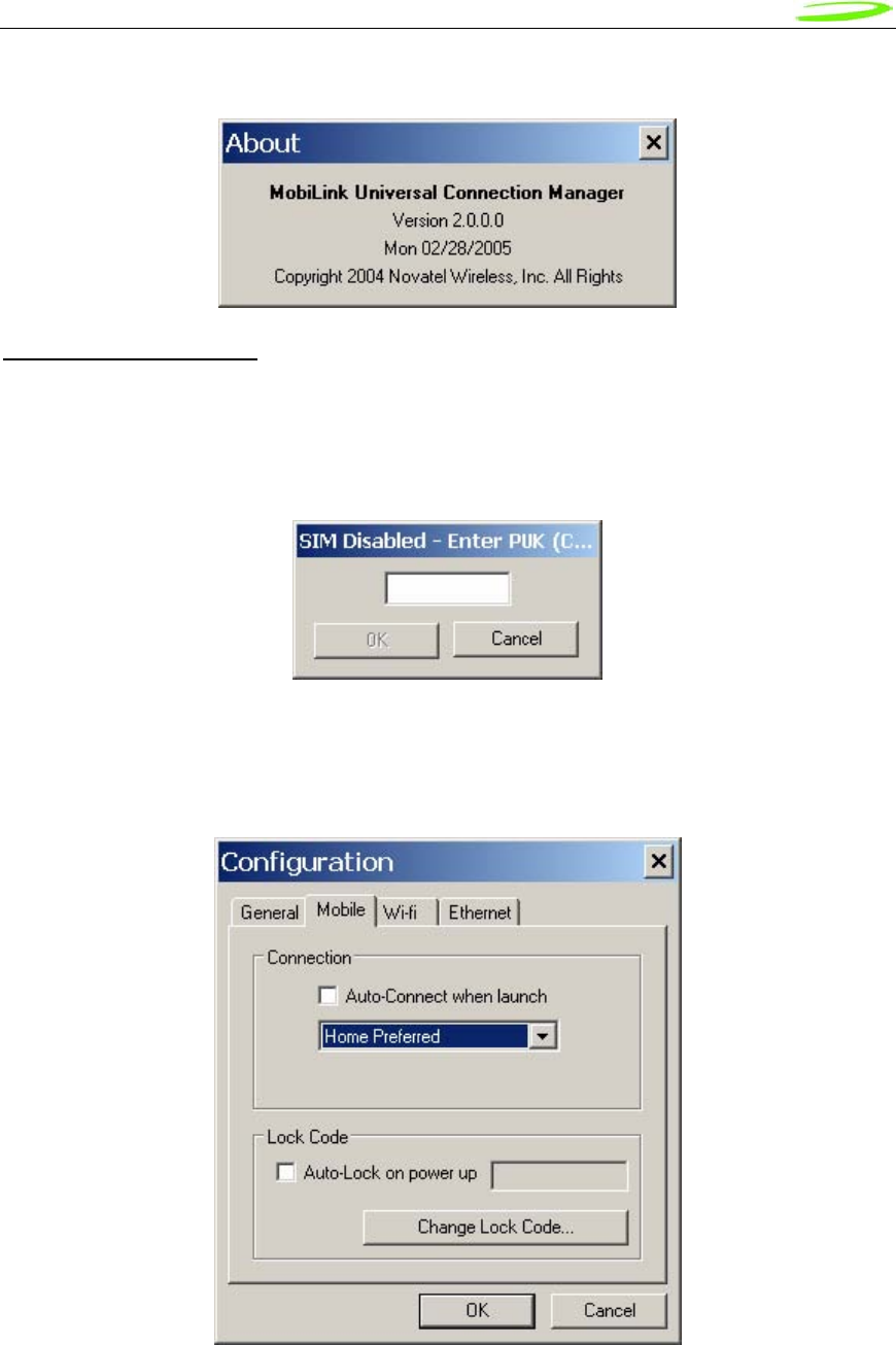
Proprietary & Confidential 100
Novatel Wireless Doc No. OM-01017857 Rev 1
Figure 41: About Dialogue
SIM/Lock Management
Upon MobiLink startup, if the device is locked on power up, a small dialog will be displayed such
as below to ask the user to enter the unlock code prior to continuing with MobiLink.
Figure 42: Enter PUK
The lock setting and code can be managed in the Mobile tab of the configuration menu shown
below.
Figure 43: Configuration Menu
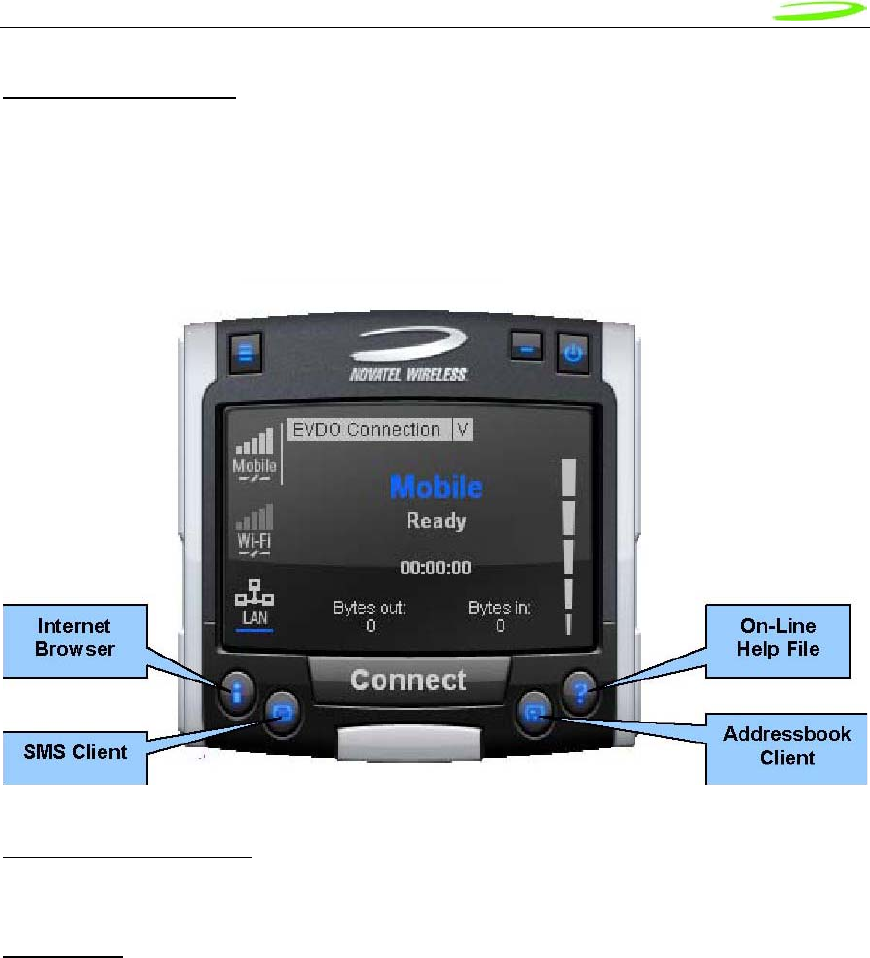
Proprietary & Confidential 101
Novatel Wireless Doc No. OM-01017857 Rev 1
Quick Access Buttons
The quick access buttons are designed to provide a launch pad for other applications. Four
buttons are provided and can be remapped to other applications. The picture below shows the
default functions assigned to the quick access buttons.
Figure 44: Quick Access Button Default Functions
Software Web Upgrade
TBD
SMS Client
The MobiLink SMS Client is used to manage reading and sending SMS messages. The SMS
Client is an application that is part of the MobiLink application suite. The design of this
application is to emulate an email Client to reduce the amount of new learning that is required to
start using this application. This application is launched from the main connection manager Quick
Access button. The following features are supported.
• Send new messages
• Reply to message
• Forward message
• Email interworking
• Concatenated SMS
• Set priority of message
• Rich text editing functions
• Printing
• Support for embedded hyper links and email links in message
• Auto language selection
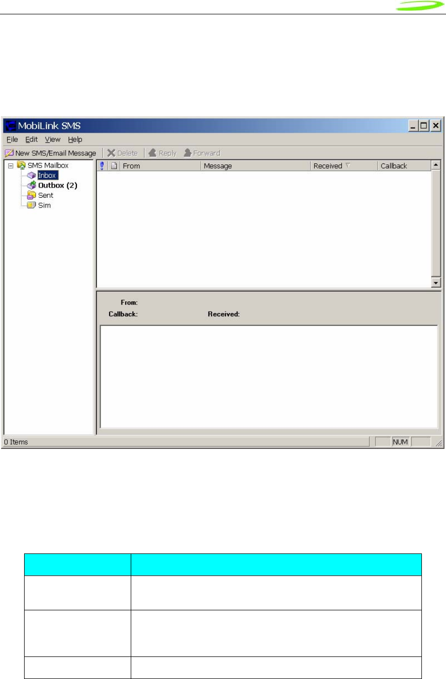
Proprietary & Confidential 102
Novatel Wireless Doc No. OM-01017857 Rev 1
• Send to multiple recipients
• Status receipt of sent messages
• Status bar to indicate number of messages, character count, etc…
Figure 45: MobiLink SMS Client
SMS Mailboxes
Very much like an email Client, the SMS Client has multiple mail boxes to store different types of
messages.
Mailbox List
Mailbox Description
Inbox All incoming SMS is delivered to this mail box and will be
highlighted if unread.
Outbox All outgoing SMS will be put into this mailbox. If the SMS has
not been sent to the card, it will be held here until it can be
sent.
Sent All sent SMS messages are placed here.

Proprietary & Confidential 103
Novatel Wireless Doc No. OM-01017857 Rev 1
SIM All SMS messages that are still stored on the SIM.
The message panel contains the key information for a list of messages. The messages can be
reorded in the message panel by clicking on the fields located on the top strip. The fields are the
following:
Fields List
Field Description
! Importance
From Where the message is from. Only shown when
Inbox is selected.
To Where the message is sent. Only shown when
Outbox or Sent box is selected.
Message Displays the first few characters of the
message
Received Time when the message is received
Sent Time when the message is sent
Callback Callback number
Menu Bar
The menu bar contains the following items:
Menu Item Description
• File o Exit Exits the application
• Edit o Undo Undo last text editing
o Cut Cut the selected text
o Copy Copy the selected text
o Paste Paste text on clipboard
o Select All Select all text in message content panel
• View o Toolbar Display tool bar
o Statusbar Display Status bar
• Help o About SMSClient Display About dialog
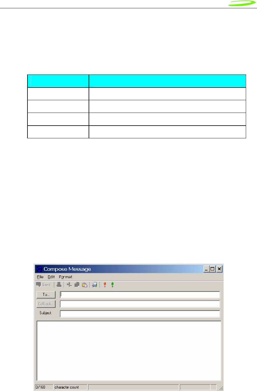
Proprietary & Confidential 104
Novatel Wireless Doc No. OM-01017857 Rev 1
Toolbar
The tool bar is accessible across the top and gives user quick access to common tasks. The tool
bar contains the following buttons:
Tool Bar Button
Button Description
New SMS Message Opens up dialog to create a new SMS message
Delete Deletes the highlighted message or group of messages.
Reply Reply to the highlighted message.
Forward Forward the contents of the highlighted message.
Status Bar
The status bar displays information about each of the mailboxes selected. It will give the number
of messages and the number of unread messages. The status bar is located on the bottom strip.
Compose Message Window
Clicking on the New SMS Message button will bring up the following dialog: This window allows
the user to enter the destination address, SMS message, a callback number for CDMA, and a
subject text. Standard text editing such as cutting, copying, pasting is supported in the message
box. In addition, the user can use the tool bar or the menu to set the priority and encoding of the
message. Both Unicode and ASCII are supported. Unicode is used to send characters not in the
standard ASCII character set.
Figure 46: Compose Message
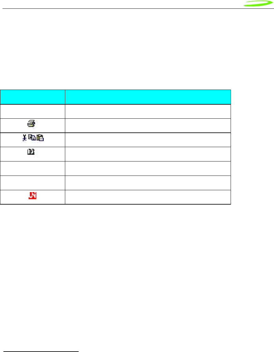
Proprietary & Confidential 105
Novatel Wireless Doc No. OM-01017857 Rev 1
For the destination address, users can chose to select from the address book by clicking on the
To button. Also, multiple destinations can be entered separated by a comma or semicolon.
The toolbar supports the following functions: Clicking on the “To” button or the Addressbook
button will bring up the following dialog to select the contact to insert into the destination field.
Multiple destination addresses can be selected.
Destination Addresses
Button Description
Send Send the SMS message
Print the SMS message
Editing functions. Cut, copy, and paste text
Open the addressbook to select from
! Emergency priority
! Urgent priority
Set Unicode encoding for message
Email Interworking
A new feature added to this version of MobiLink is the ability for email interworking. What this
feature does is to allow an email message to be sent over an SMS message. If the user types in
an email address in the To field, the application will automatically format the SMS message so
that the SMSC on the network side will forward it as an email.
The recipient of this email can simply reply to the message and the message will be forwarded
back to the wireless device.
Concatenated SMS
With the addition of email interworking, the ability to send an SMS that is longer than the limited
160 characters is very important. To address that issue, the SMS Client will allow the user to
enter a long message and automatically segment the message and send it as separate SMS with
a special tag to indicate the messages are segments of a long message.
Addressbook Features
The MobiLink address book allows the management of phone numbers on the SIM, Windows
Address Book and Outlook. The following screen shows the address book Client.
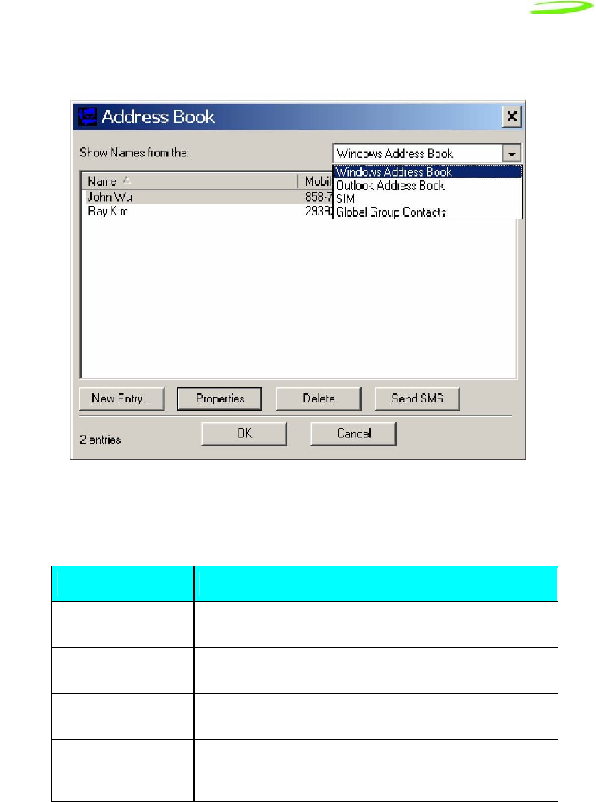
Proprietary & Confidential 106
Novatel Wireless Doc No. OM-01017857 Rev 1
Figure 47: Address Book
The address book Client has a selection box that allows the user to chose which address book to
view. The following addresses can be selected:
Address Books
Address book Description
Windows Address
Book This is the native Windows Addressbook that is part of
Windows Accessories folder
Outlook Address
Book This is the local Outlook Addressbook. This is only
accessible if Outlook is installed on the computer
SIM This is the address book located on the 3G device or the
SIM of the device
Global Group
Contact
This is the group contacts that contain distribution lists
created by the user. This list can contain contacts from
any of the above address books
User can create, delete, and view contact properties as well as send an SMS message using the
selected contact by clicking on one of the buttons on the bottom of the Address Book Client.
Global Group Contact
Global Group Contact feature allows users to create distribution lists for sending SMS.
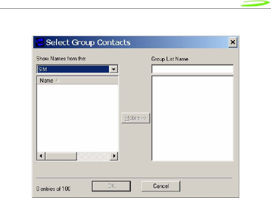
Proprietary & Confidential 107
Novatel Wireless Doc No. OM-01017857 Rev 1
Figure 48: Select Group Contacts
When the user chooses to create a Global Group Contact, a new dialog will be opened up to
allow the user to select from the different address books and move them to create a new
distribution list. The total number in a distribution list is up to 100. The list can contain a mixture
from different address books and can contain both mobile numbers as well as email addresses.

Proprietary & Confidential 108
Novatel Wireless Doc No. OM-01017857 Rev 1
Appendix A - Customer Configuration & ID’s
Introduction
This appendix contains introductory guidance on customer configuration of the Novatel Wireless
PCI Express Mini-cards
USB ID
The USB ID sets the USB Vendor ID and Product ID fields (VID-PID) that are reported to the
host computer during device enumeration. These ID are configured in the Customer PRI
document.
HW ID
An AT commands can be used to identify the Hardware Revision of particular PCI Express Mini-
cards. This can be useful tracking form, fit and function hardware changes to a mini card.
IMEI Numbers (HSDPA)
IMEI numbers are assigned on a block basis to be associated with specific laptop/handheld
platforms. The logistics for the assignment are detailed in the Customer PRI document
completed with Novatel Wireless.

Proprietary & Confidential 109
Novatel Wireless Doc No. OM-01017857 Rev 1
HSDPA Product Release Instruction (PRI)
The purpose of this section is to provide information on customizable UMTS / HSDPA firmware
features. The UMTS/HSDPA FIRMWARE FEATURES are detailed on the next page.
INTRODUCTION
The intended design of firmware for each UMTS/HSDPA product in the portfolio is to maintain a
single code base. This means that to provide core features to customers the firmware must be
configurable. This section details the configurable features of Novatel Wireless UMTS/HSDPA
products including the U630, xU7x0 and xU860/U870.
Common Features
A common feature is a UMTS/HSDPA modem configuration which may be applicable to any
customer. Although the feature operates in the same manner for any Novatel Wireless modem, it
may not necessarily be implemented on all platforms. Further, the feature may have been
introduced in a particular version of firmware
The following sections describe the common features defined for NVTL UMTS/HSDPA modems.
The feature descriptions are formatted in the manner shown below.
Name The engineering name for the feature of interest.
States The possible configurations for the feature. Defaults, if they apply, are highlighted in
BOLD font.
Devices A list of devices that support the feature.
FW Version A list of firmware BUILDs that support the feature.
AT Command A reference to an applicable AT command which can control the feature. Provided for
field support personnel.
NV Item The NV Item that stores the data. Provided for engineering, field engineering and
fulfillment personnel.

Proprietary & Confidential 110
Novatel Wireless Doc No. OM-01017857 Rev 1
Network Lock (aka SIM/USIM Lock)
The Network Lock feature allows a service provider to prohibit a modem from connecting to their
network unless the modem uses a SIM/USIM (herein referred to as SIM) that is provided by that
carrier. Network Lock consists of two locking procedures, Network Code Lock (NCL) and Home
Location Register Lock (HLRL). Both NCL and HLRL evaluate fields contained in the SIM to
determine if the modem is in a locked or unlock state. The fields of interest are both contained in
the International Mobile Subscriber Identity (IMSI). The IMSI is usually fifteen digits long starting
with the Mobile Country Code (MCC), followed by the Mobile Network Code (MNC) and suffixed
by the unique Mobile Subscriber Identity Number (MSIN) within the network's customer base. The
NCL evaluates the MNC/MCC pair while the HLRL evaluates the MSIN and the MNC/MCC pair.
The Network Lock for both NCL and HLRL are performed at power-up. The modem determines if
NCL and HLRL are enabled. If NCL is enabled the MNC/MCC pair is extracted from the IMSI then
validated against the list of MNC/MCC pairs stored in the modem. If a match is found the modem
is unlocked and is able to attach to the network. HLRL allows service providers to limit the
roaming area of the user. If HLRL is enabled, the algorithm evaluates MNC/MCC pair, the first
three leading digits of the MSIN which contains HLR-value (2 digits) and a National Destination
Code (NDC) (1 digit). Similar to the NCL, the three fields are compared against the list
programmed into the modem to determine the lock state. In the unlocked state the modem is able
to attach to the network.
Network Lock Code
In the NCL mode of Network Lock the modems supports up to 30 MNC/MCC pairs that can be
specified.
In the HLRL mode of Network Lock the modem, ONLY a single MNC/MCC pair may be specified.
Name NetworkLockCode
States Customer to provide MNC/MCC pairs
Devices U630, xU7x0, xU860/870
FW Version All
AT Command AT$NWNPC
NV Item
NW_NV_NETWORK_LOCK_CODES_I
HLR Range
In the HLRL mode of Network Lock the modem supports up to 4 sets of HLR ranges. For each
HLR Range, there is a single digit NDC value, and 0..14 sets of min and max values specifying
HLR. For all HLR min-max pairs, the max value must be greater than or equal to the min value.
Name HLRLockHLRRange
States Customer to provide HLR Lock Ranges
Devices xU7x0, xU860/U870

Proprietary & Confidential 111
Novatel Wireless Doc No. OM-01017857 Rev 1
FW Version All
AT Command AT$NWHLR
NV Item NW_NV_HLR_RANGE_I

Proprietary & Confidential 112
Novatel Wireless Doc No. OM-01017857 Rev 1
Universal Serial Bus Identity (USBID)
The USB ID is the identifier which is presented by the modem to the host operating system during
device enumeration. As part of the enumeration process the host associates this value to a
device driver. It is possible to provide customer specific drivers with the use of the USB ID.
Name UsbId
States Customer to provide PID and VID pairs if customer drivers are utilized.
Devices xU7x0, xU860/U870
FW Version All
AT Command N/A
NV Item NW_NV_USB_ID_I

Proprietary & Confidential 113
Novatel Wireless Doc No. OM-01017857 Rev 1
Four Com Port Support
The Four Com port feature enables the following ports: modem, status, QXDM and PC/SC port. If
EAP-SIM support is required, this feature must be enabled.
Name FourComPortsEnable
States Customer to select - Enable, Disable
Devices xU7x0, xU860/U870
FW Version xU7x0 – Build 29 and above
xU860/U870 – Build 7 and above
AT Command AT$NWFOURPORTENABLE
NV Item NW_NV_FOUR_PORTS_ENABLED_I

Proprietary & Confidential 114
Novatel Wireless Doc No. OM-01017857 Rev 1
HEDGE/WEDGE Selection
The firmware supports the selection of operation according to R99 (WEDGE) and R5 (HEDGE)
using this configuration option.
Name WedgeOnlyEnable
States Customer to select - WEDGE, HEDGE
Devices xU7x0, xU860/U870
FW Version xU7x0 – Build 15.4 and above
xU860/U870 - All
AT Command N/A
NV Item NV_WCDMA_RRC_VERSION_I

Proprietary & Confidential 115
Novatel Wireless Doc No. OM-01017857 Rev 1
Mini-Card Feature Additions
The following sections detail the features which are ONLY applicable to mini-card
Wireless WAN Disable
This feature provides the following functionality: monitor an input which is under laptop control to
set the state of the modem between Online Mode (OM) and Low Power Mode (LPM). In the OM
state, if the input signals to disable the WAN, the modem will enter LPM and will cease
transmitting until the signal is restored and the modem returns to OM. Upon entering LPM from
OM, the modem will detach from the network with a “power down” reason code and disable the
transmitter. In OM, the modem attaches to the network and can allow PDP context activation.
The functionality above can also be controlled via a software command ($NWDIS). This allows
applications to control the state of the modem so that users can disable the transmitter in
situations such as boarding an aircraft.
Name WwanDisableMonitor
States Customer to select - Enable, Disable
Devices xU7x0, xU860/U870
FW Version All
AT Command AT$NWDIS
NV Item NW_NV_W_DISABLE_MONITOR_I

Proprietary & Confidential 116
Novatel Wireless Doc No. OM-01017857 Rev 1
Wireless WAN LED Function
This feature controls the preset functionality of the LED drivers as described below:
Function 0: the LED is driven HIGH when the unit is disabled from transmitting, and LOW when
unit is allowed to transmit.
Function 1: the LED operates as defined by NVTL standard LED behavior.
Name WwanLedFunction
States Customer to select – Function 1, Function 2
Devices xU7x0, xU860/U870
FW Version All
AT Command N/A
NV Item NW_NV_LED_WWAN_FUNCTION_I

Proprietary & Confidential 117
Novatel Wireless Doc No. OM-01017857 Rev 1
Thermal Limits
This feature provides a monitor of the temperature of the mini-card. Presently, the hot and
smoking limits provide the same functionality. At temperatures below the high threshold, the
modem will operate in its normal mode. If the modem temperature increases past the high
temperature limit the modem will be forced to Low Power Mode (LPM) until the modem
temperature is reduced below the warm temperature limit at which time, the modem will return to
normal operation.
Name ThermalLimits
States Customer Defined Limits
Devices xU7x0, xU860/U870
FW Version All
AT Command N/A
NV Item NW_NV_THERMAL_LIMITS_I

Proprietary & Confidential 118
Novatel Wireless Doc No. OM-01017857 Rev 1
Customer Requested Features
The following sections contain configurable features specified by a carrier and implemented by
Novatel Wireless. These items should ONLY be available in a PRI document which is specific to
that carrier or customer selling products on the specific carriers identified.
CarrierX
CarrierX has asked for 2 feature developments the first PWI was to support a product launch,
namely the Home Zone product and second is a network feature needed to support the sharing of
their network with CarrierY.
PWI Service
The PWI subscription allows PWI users to access the internet at home for a special tariff. Voice
services are not allowed.
PWI subscribers can only access the CarrierX network. Access to TMD or other foreign networks
is barred at the network. PWI subscribers will get a special PWI UICC and a PWI device.
The PWI device is a gateway between UMTS and a local data interface like W-LAN, LAN or
Bluetooth, consisting of a Novatel Wireless PCMCIA card, one or more networking interfaces to a
e.g. laptop, and a software (as firmware or linux or Windows based) to manage the different
modules as well as to support the PWI zoning service.
The PWI UICC shall only be able to work with PWI Devices. The PWI device shall only be able to
work with PWI UICCs.
The PWI device accesses only UMTS networks, not GSM. Thus, PWI subscribers can effectively
only use the CarrierX UMTS network.

Proprietary & Confidential 119
Novatel Wireless Doc No. OM-01017857 Rev 1
PWI Zoning Enabled – SIM Applet
Enabling this feature allows the PWI application to run from a SIM applet provided by CarrierX.
Name NwPWIZoningAppEnabled
States Enable, Disable
Devices U630, xU7x0, xU860/U870
FW Version All
AT Command AT$NWHLR
NV Item NW_NV_PWI_SIM_APP_ENABLED_I

Proprietary & Confidential 120
Novatel Wireless Doc No. OM-01017857 Rev 1
PWI Zoning Enabled – Device Applet
Enabling this feature allows the PWI application to run from the modem and override the SIM
applet provided by CarrierX.
Name NwPWIDeviceAppEnabled
States Enable, Disable
Devices U630, xU7x0, xU860/U870
FW Version All
AT Command N/A
NV Item NW_NV_PWI_DEVICE_APP_ENABLED_I