Omron 6CYSIDV6800308 RFID System User Manual Z262 E1 04
Omron Corporation RFID System Z262 E1 04
Omron >
Contents
- 1. Manual 1
- 2. Manual 2
Manual 1
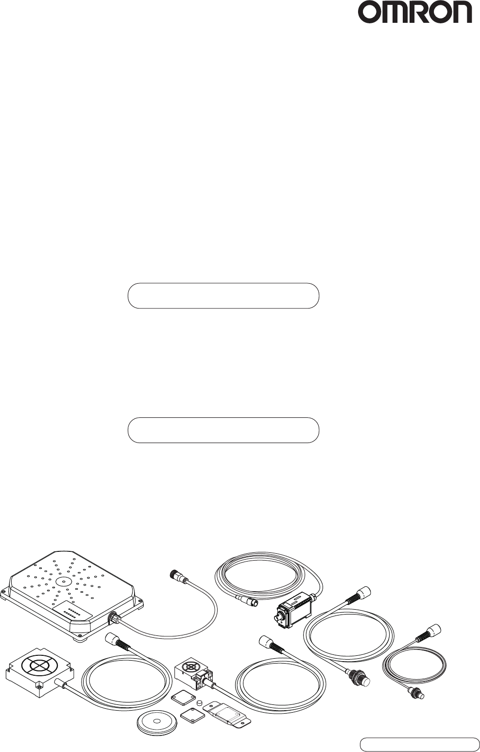
RFID System
V680 Series
Cat. No.: Z262-E1-04
Amplifier and Antennas
V680-HA63A
V680-HS51
V680-HS52
ID Tags
V680-D1KP52MT
V680-D1KP66T
V680-D1KP66MT
User's Manual for Amplifiers, Antennas, and ID Tags
(EEPROM)
V680-HS63
V680-D1KP66T-SP
V680-HS65
V680-H01-V2
V680-D1KP58HT

Introduction
Thank you for purchasing a V680-series RFID System. This manual describes the functions, performance,
and application methods needed for optimum use of the V680-series RFID System.
Please observe the following items when using the RFID System.
• Allow the RFID System to be installed and operated only by qualified specialist with a sufficient
knowledge of electrical systems.
• Read and understand this manual before attempting to use the RFID System and use the RFID Sys-
tem correctly.
• Keep this manual in a safe and accessible location so that it is available for reference when required.

Introduction Section 1 Section 2 Section 3 Section 4 Section 5
Introduction
Section 1
Section 2
Section 3
Section 4
Section 5
READ AND UNDERSTAND THIS DOCUMENT
Product Overview
Specifications and Performance
Communications Specifications
Installation
Chemical Resistance
RFID System
V680-HA63A Amplifier
V680-HS51 Antenna
V680-HS52 Antenna
V680-HS63 Antenna
V680-HS65 Antenna
V680-H01-V2 Antenna
V680-D1KP52MT ID Tag
V680-D1KP66T ID Tag
V680-D1KP66MT ID Tag
V680-D1KP66T-SP ID Tag
V680-D1KP58HT ID Tag
User's Manual

2
Introduction
RFID System
User's Manual
Introduction
READ AND UNDERSTAND THIS DOCUMENT
Please read and understand this document before using the products. Please consult your OMRON representative if you have any questions or comments.
WARRANTY
OMRON’s exclusive warranty is that the products are free from defects in materials and workmanship for a period of one year (or other period if specified)
from date of sale by OMRON.
OMRON MAKES NO WARRANTY OR REPRESENTATION, EXPRESS OR IMPLIED, REGARDING NON-INFRINGEMENT, MERCHANTABILITY, OR FIT-
NESS FOR PARTICULAR PURPOSE OF THE PRODUCTS. ANY BUYER OR USER ACKNOWLEDGES THAT THE BUYER OR USER ALONE HAS
DETERMINED THAT THE PRODUCTS WILL SUITABLY MEET THE REQUIREMENTS OF THEIR INTENDED USE. OMRON DISCLAIMS ALL OTHER
WARRANTIES, EXPRESS OR IMPLIED.
LIMITATIONS OF LIABILITY
OMRON SHALL NOT BE RESPONSIBLE FOR SPECIAL, INDIRECT, OR CONSEQUENTIAL DAMAGES, LOSS OF PROFITS OR COMMERCIAL LOSS IN
ANY WAY CONNECTED WITH THE PRODUCTS, WHETHER SUCH CLAIM IS BASED ON CONTRACT, WARRANTY, NEGLIGENCE, OR STRICT LIABIL-
ITY.
In no event shall responsibility of OMRON for any act exceed the individual price of the product on which liability is asserted.
IN NO EVENT SHALL OMRON BE RESPONSIBLE FOR WARRANTY, REPAIR, OR OTHER CLAIMS REGARDING THE PRODUCTS UNLESS OMRON’S
ANALYSIS CONFIRMS THAT THE PRODUCTS WERE PROPERLY HANDLED, STORED, INSTALLED, AND MAINTAINED AND NOT SUBJECT TO CON-
TAMINATION, ABUSE, MISUSE, OR INAPPROPRIATE MODIFICATION OR REPAIR.
SUITABILITY FOR USE
THE PRODUCTS CONTAINED IN THIS DOCUMENT ARE NOT SAFETY RATED. THEY ARE NOT DESIGNED OR RATED FOR ENSURING SAFETY OF
PERSONS, AND SHOULD NOT BE RELIED UPON AS A SAFETY COMPONENT OR PROTECTIVE DEVICE FOR SUCH PURPOSES. Please refer to
separate catalogs for OMRON's safety rated products.
OMRON shall not be responsible for conformity with any standards, codes, or regulations that apply to the combination of products in the customer’s applica-
tion or use of the product.
At the customer’s request, OMRON will provide applicable third party certification documents identifying ratings and limitations of use that apply to the prod-
ucts. This information by itself is not sufficient for a complete determination of the suitability of the products in combination with the end product, machine,
system, or other application or use.
The following are some examples of applications for which particular attention must be given. This is not intended to be an exhaustive list of all possible uses
of the products, nor is it intended to imply that the uses listed may be suitable for the products:
• Outdoor use, uses involving potential chemical contamination or electrical interference, or conditions or uses not described in this document.
• Nuclear energy control systems, combustion systems, railroad systems, aviation systems, medical equipment, amusement machines, vehicles, safety
equipment, and installations subject to separate industry or government regulations.
• Systems, machines, and equipment that could present a risk to life or property.
Please know and observe all prohibitions of use applicable to the products.
NEVER USE THE PRODUCTS FOR AN APPLICATION INVOLVING SERIOUS RISK TO LIFE OR PROPERTY WITHOUT ENSURING THAT THE SYSTEM
AS A WHOLE HAS BEEN DESIGNED TO ADDRESS THE RISKS, AND THAT THE OMRON PRODUCT IS PROPERLY RATED AND INSTALLED FOR
THE INTENDED USE WITHIN THE OVERALL EQUIPMENT OR SYSTEM.
PERFORMANCE DATA
Performance data given in this document is provided as a guide for the user in determining suitability and does not constitute a warranty. It may represent the
result of OMRON’s test conditions, and the users must correlate it to actual application requirements. Actual performance is subject to the OMRON Warranty
and Limitations of Liability.
CHANGE IN SPECIFICATIONS
Product specifications and accessories may be changed at any time based on improvements and other reasons.
It is our practice to change model numbers when published ratings or features are changed, or when significant construction changes are made. However,
some specifications of the product may be changed without any notice. When in doubt, special model numbers may be assigned to fix or establish key spec-
ifications for your application on your request. Please consult with your OMRON representative at any time to confirm actual specifications of purchased
products.
DIMENSIONS AND WEIGHTS
Dimensions and weights are nominal and are not to be used for manufacturing purposes, even when tolerances are shown.
ERRORS AND OMISSIONS
The information in this document has been carefully checked and is believed to be accurate; however, no responsibility is assumed for clerical, typographical,
or proofreading errors, or omissions.
PROGRAMMABLE PRODUCTS
OMRON shall not be responsible for the user’s programming of a programmable product, or any consequence thereof.
COPYRIGHT AND COPY PERMISSION
This document shall not be copied for sales or promotions without permission. This document is protected by copyright and is intended solely for use in con-
junction with the product. Please notify us before copying or reproducing this document in any manner, for any other purpose. If copying or transmitting this
document to another, please copy or transmit it in its entirety.

3
RFID System
User's Manual
Introduction
Introduction
Alert Symbols for Safe Use
The following symbols are used in this manual to indicate precautions that must be observed to ensure safe
use of the V680-HS51, V680-HS52, V680-HS63, V680-HS65, V680-H01-V2, V680-HA63A, V680-
D1KP52MT, V680-D1KP66T, V680-D1KP66MT, V680-D1KP66T-SP, and V680-D1KP58HT. The precautions
provided here contain important safety information. Be sure to observe these precautions.
The following signal words are used in this manual.
Meanings of Alert Symbols
Warning
The Products conform to the following overseas regulations and standards.
1.The United States
FCC NOTICE
This device complies with part 15 of the FCC Rules. Operation is subject to the following two conditions:
(1) This device may not cause harmful interference.
(2) This device must accept any interference received, including interference that may cause undesired operation.
FCC WARNING
Changes or modifications not expressly approved by the party responsible for compliance could void the user's author-
ity to operate the equipment.
Do not remove the ferrite core (TDK Type ZCAT1730-0730A:V680-HS52/-HS63/-HS65, TDK Type ZCAT1525-
0430AP:V680-HS51, TDK Type ZCAT2035-0930:V680-H01-V2) installed on the cables to suppress RF interference.
Safety Precautions
Indicates a potentially hazardous situation which, if not avoided, will result in minor or mod-
erate injury, or may result in serious injury or death. Additionally, there may be significant
property damage.
Indicates general prohibitions for which there is no specific symbol.
These Products are not designed to be used either directly or indirectly in applications that detect human
presence for the purpose of maintaining safety. Do not use these Products as a sensing means for protect-
ing human lives.
Regulations and Standards
Amplifier Antenna
This product complies with Part 15 Subpart C of the FCC Rules.
FCC ID: E4E6CYSIDV6800406
V680-HA63A V680-HS51
V680-HS52
V680-HS63
V680-HS65
This product complies with Part 15 Subpart C of the FCC Rules.
FCC ID: E4E6CYSIDV6800308
--- V680-H01-V2
WARNING
WARNING
4
Introduction
RFID System
User's Manual
Introduction
2. Europe
3. Japan
4. Canada
This device complies with RSS-Gen of IC Rules.
Operation is subject to the following two conditions:(1) this device may not cause harmful interference, and (2) this
device must accept any interference received, including interference that may cause undesired operation.
Amplifier Antenna
(Radio and Telecommunication Terminal Equipment Directive 1999/5/EC) V680-HA63A V680-HS51
V680-HS52
V680-HS63
V680-HS65
Radio:
EMC:
Safety:
EN 300 330-2
EN 301 489-1
EN 301 489-3
EN 61010 --- V680-H01-V2
English Hereby, Omron, declares that the RFID System, V680-HS51 Series, V680-HS52 Series, V680-HS63 Series, V680-HS65 Series, V680-H01-V2 Series and
V680-HA63A Series are in compliance with the essential requirements and other relevant provisions of Directive 1999/5/EC.
Finnish Omron vakuuttaa täten että RFID Säännös, V680-HS51 Series, V680-HS52 Series, V680-HS63 Series, V680-HS65 Series, V680-H01-V2 Series, V680-
HA63A Series tyyppinen laite on direktiivin 1999/5/EY oleellisten vaatimusten ja sitä koskevien direktiivin muiden ehtojen mukainen.
Dutch Hierbij verklaart Omron dat het toestel de RFID Systeem, V680-HS51 ´Serie, V680-HS52 ´Serie, V680-HS63 ´Serie, V680-HS65 ´Serie, V680-H01-V2
´Serie, V680-HA63A ´Serie in overeenstemming is met de essentiële eisen en de andere relevante bepalingen van richtlijh 1999/5/EG.
French Par la présente Omron déclare que la RFID Système, V680-HS51 Série, V680-HS52 Série, V680-HS63 Série, V680-HS65 Série, V680-H01-V2 Série,
V680-HA63A Série sont conforme aux exigences essentielles et aux autres dispositions pertinentes de la directive 1999/5/CE.
Swedish Härmed intygar Omron att den RFID System, V680-HS51 Serie, V680-HS52 Serie, V680-HS63 Serie, V680-HS65 Serie, V680-H01-V2 Serie, V680-
HA63A Serie stär l överensstämmelse med de väsentliga egenskapskrav och övriga relevanta bestämmelser som framgår av direktiv 1999/5/EG.
Danish Undertegnede Omron erklærer herved, at følgende den RFID System, V680-HS51 Serie, V680-HS52 Serie, V680-HS63 Serie, V680-H01-V2 Serie,
V680-HS65 Serie, 680-HA63A Serie overholder de væsentlige krav og øvrige relevante krav i direktiv 1999/5/EF.
German Hiermit erklärt Omron, die RFID System, V680-HS51 Serie, V680-HS52 Serie, V680-HS63 Serie, V680-HS65 Serie, V680-H01-V2 Serie, V680-HA63A
Serie in Übereinstimmung mit den grundlegenden Anforderungen und den anderen relevanten Vorschriften der Richtlinie 1999/5/EG befindet. (BMWi)
Greek ME THN ΠAPOYSA Omron ΔHΛONEI RFID O
’YO
’ΓΗΜΑ, V680-HS51 O
’EIPA, V680-HS52 O
’EIPA, V680-HS63 O
’EIPA, V680-HS65 O
’EIPA, V680-
H01-V2 O
’EIPA, V680-HA63A O
’EIPA SYMMOPF ONETAI ΠPOS TIS OYSIOΔEIS AΠAITHSEIS KAI TIS ΛOIΠES SXETIKES ΔIATAΞEIS THS
OΔHΓIAS 1999/5/EK.
Italian Con la presente Omron dichiara che la RFID Sistema, V680-HS51Serie, V680-HS52Serie, V680-HS63 Serie,V680-HS65 Serie,V680-H01-V2 Serie,
V680-HA63A Serie sono conforme ai requisiti essenziali ed alle altre disposizioni pertinenti stabilite dalla direttiva 1999/5/CE.
Spanish Por medio de la presente Omron declara que el RFID Sistema, V680-HS51 Serie, V680-HS52 Serie, V680-HS63 Serie, V680-HS65 Serie, V680-H01-V2
Serie, V680-HA63A Serie esta conforme a los requisitos esenciales y cualesquiera otras disposiciones aplicables o exigibles de la Directiva 1999/5/CE.
Portuguese Omron declara que a RFID Sistema, V680-HS51 Série, V680-HS52 Série, V680-HS63 Série, V680-HS65 Série, V680-H01-V2 Série, V680-HA63A
Série ser conforme com os tequisitos essenciais e outras disposições da Directiva 1999/5/CE.
Romanian Prin prezenta, Omron declar c acest V680-HS51, V680-HS52, V680-HS63, V680-HS65, V680-H01-V2, V680-HA63A este conform cu cerin ele prin-
cipale çi cu celelalte prevederi relevanate ale Directivei 1999/5/EC.
Amplifier Antenna
Equipment using high frequencies: Inductive Reading/Writing Communications Equipment
Conforming standards: Inductive Reading/Writing Communications Equipment; Standard: ARIB STD-T82
EC-06019
V680-HA63A V680-HS51
V680-HS52
V680-HS63
V680-HS65
Equipment using high frequencies: Inductive Reading/Writing Communications Equipment
Conforming standards: Inductive Reading/Writing Communications Equipment; Standard: ARIB STD-T82
EC-@@@@@
--- V680-H01-V2
Amplifier Antenna
IC ID:850J-V68HA63A V680-HA63A V680-HS51
V680-HS52
V680-HS63
V680-HS65
IC ID:850J-V6800308 --- V680-H01-V2

5
RFID System
User's Manual
Introduction
Introduction
5. China
6. Korea
7. Taiwan
Amplifier Antenna
CMII ID:2008DJ0884 V680-HA63A V680-HS51
CMII ID:2007DJ0577 V680-HA63A V680-HS52-R
CMII ID:2007DJ0575 V680-HA63A V680-HS52-W
CMII ID:2007DJ0571 V680-HA63A V680-HS63-R
CMII ID:2007DJ0573 V680-HA63A V680-HS63-W
CMII ID:2008DJ0141 V680-HA63A V680-HS65-R
CMII ID:2008DJ0142 V680-HA63A V680-HS65-W
Amplifier Antenna
OMR-V680-HA63A V680-HA63A V680-HS51
V680-HS52
V680-HS63
V680-HS65
Amplifier Antenna
CCAB07LP1220T4 V680-HA63A V680-HS51
V680-HS52
V680-HS63
V680-HS65

6
Introduction
RFID System
User's Manual
Introduction
8. Hong Kong
9. Singapore
10.Malaysia
If the product is used in Malaysia, a label must be attached on-site to the side of the V680-HA63A.
Please consult your OMRON sales representative for details.
11.Philippine
12.Mexico
Este equipo opera a titulo secundario, consecuentemente, debe aceptar interferencias perjudiciales incluyendo
equipos de la misma clase y puede no causar interferencias a sistemas operando a titulo primario.
13.Thailand
The certification is unnecessary, so the product can be used.
Changes or modifications not expressly approved by the party responsible for compliance could void the user's author-
ity to operate the equipment.
Do not remove the ferrite core (TDK Type ZCAT1730-0730A:V680-HS52/-HS63/-HS65, TDK Type ZCAT1525-
0430AP:V680-HS51, TDK Type ZCAT2035-0930:V680-H01-V2) installed on the cables to suppress RF interference.
Amplifier Antenna
LP407043 V680-HA63A V680-HS52
V680-HS63
Amplifier Antenna
S0294-07 V680-HA63A V680-HS51
V680-HS52
V680-HS63
V680-HS65
Amplifier Antenna
A011578 V680-HA63A V680-HS51
V680-HS52
V680-HS63
V680-HS65
Amplifier Antenna
ESD-0702971C V680-HA63A V680-HS51
V680-HS52
V680-HS63
V680-HS65
Amplifier Antenna
COFETEL:RLVOMV607-622-A2 V680-HA63A V680-HS51
V680-HS52
V680-HS63
V680-HS65

7
RFID System
User's Manual
Introduction
Introduction
Be sure to observe the following precautions to ensure safe use of the Products.
1. Do not use the Products in environments with flammable, explosive, or corrosive gasses.
2. Do not attempt to disassemble, repair, or modify any Product.
3. Tighten mounting screws securely.
4. Because a cable has a locking mechanism, make sure that it has been locked before using the cable.
5. Do not allow water or pieces of wire to enter from openings in the case. Doing so may cause fire or
electric shock.
6. Turn OFF the Controller power supply before mounting or removing an Antenna or Amplifier.
7. Turn OFF the power supply to the Controller before changing settings.
Attach a Setting switch protection Cover after setting Switch.
8. If an error is detected in any Product, immediately stop operation and turn OFF the power supply. Consult
with an OMRON representative.
9. Dispose of the Products as industrial waste.
10. Observe all warnings and precautions given in the body of this manual.
11. Do not touch the product immediately after usage at high temperatures. Doing so may occasionally result
in burning.
12. Do not open the back cover of the V680-H01-V2 antenna.
13. Do not install the Products near equipment that generates a large amount of heat, such as a heater,
transformer, or high-capacity resistor.
Precautions for Safe Use

8
Introduction
RFID System
User's Manual
Introduction
Always observe the following precautions to prevent operation failures, malfunctions, and adverse effects on
performance and equipment.
1. Installation Environment
Do not use the Products in the following locations.
• Locations exposed to direct sunlight
• Locations exposed to corrosive gases, dust, metallic powder, or salts
• Locations not within the specified operating temperature range
• Locations subject to rapid changes in temperature or condensation
• Locations not within the specified humidity range
• Locations subject to direct vibration or shock outside the specified ranges
• Locations subject to spray of water, oil, or chemicals
2. Installation
The Products communicate with Tags using the 13.56-MHz frequency band. Some motors, inverters,
and switching power supplies generate noise that can affect communications with the Tags and cause
errors. If such devices are located near the Tags, always test operation in advance to confirm whether
the system will be affected.
• Observe the following precautions to minimize the effects of normal noise.
(1) Ground all metal objects in the vicinity of the Products to 100 Ω or less.
(2) Do not use the Products near high-voltage or high-current lines.
• Do not use non-waterproof Products in an environment where mist is present.
• Do not expose the Products to chemicals that adversely affect the Product materials.
• When mounting the Products, tighten the screws to the following torques.
V680-HS51: 6 N⋅m
V680-HS52: 40 N⋅m
V680-HS63: 1.2 N⋅m
V680-HS65: 1.2 N⋅m
V680-H01-V2: 1.2 N⋅m
• Do not pull the Antenna connector over the power of 30 N.
The Antenna connector may be broken.
• Transmission will not be possible if the front and back panels are mistakenly reversed and the Unit is
mounted to a metallic surface.
V680-D1KP66MT
• The transmission distance will be reduced when the Unit is not mounted to a metallic surface.
V680-D1KP66MT
• If multiple Antennas are mounted near each other, communications performance may decrease due
to mutual interference. Refer to Installing Antennas on page 56 and check to make sure there is no
mutual interference.
• Depending on the operating environment, the case surface may become fogged, but basic perfor-
mance will not be affected.
Precautions for Correct Use

9
RFID System
User's Manual
Introduction
Introduction
3. Storage
Do not store the Products in the following locations.
• Locations exposed to direct sunlight
• Locations exposed to corrosive gases, dust, metallic powder, or salts
• Locations not within the specified storage temperature range
• Locations subject to rapid changes in temperature or condensation
• Locations not within the specified storage humidity range
• Locations subject to direct vibration or shock outside the specified ranges
• Locations subject to spray of water, oil, or chemicals
4. Cleaning
• Do not clean the Products with paint thinner or the equivalent. Paint thinner, benzene, acetone, and
kerosene or the equivalent will dissolve the resin materials and case coating.
5. Combination of the Amplifier
• Use the V680-D1KP52MT, V680-D1KP66T, V680-D1KP66MT, and V680-D1KP66T-SP ID Tags in
combination with only the V680-HA63A Amplifier. Do not use these ID Tags together with the V680-
HA63B Amplifier.

10
Introduction Meanings of Symbols
RFID System
User's Manual
Introduction
Meanings of Symbols
Indicates particularly important points related to a function, including precautions and application advice.
Indicates page numbers containing relevant information.

11
RFID System
User's Manual
Introduction
Introduction
Table of Contents
Safety Precautions 3
Regulations and Standards 3
Precautions for Safe Use 7
Precautions for Correct Use 8
Meanings of Symbols 10
Table of Contents 11
Section 1 Product Overview 13
Features 14
Product Configuration 15
Section 2 Specifications and Performance 17
Antennas with Separate Amplifier 18
Antennas with Built-in Amplifier 25
Amplifier 30
Tags 33
Section 3 Communications Specifications 43
Communications Distances 44
Communication Time (Reference) 53
Section 4 Installation 55
Installing Antennas 56
Mounting Amplifiers 65
Installing Tags 67
Section 5 Chemical Resistance 79
Chemical Resistance of the Antennas 80
Chemical Resistance of Tags 81
Degree of Protection 85
Revision History 88

12 RFID System
User's Manual
Introduction
Introduction
MEMO

Section 1 Product Overview
13
RFID System
User's Manual
Section 1
Product Overview
Features 14
Product Configuration 15

14
Section 1 Features
RFID System
User's Manual
Section 1
Product Overview
Features
The V680-series RFID System actively supports many different types of system, such as distributed-control
systems and many-product, small-lot production systems, with non-contact data communications using
electromagnetic induction.
Non-contact Data Communications
The V680 Series uses electromagnetic induction to enable non-contact, bi-directional data communi-
cations between Antennas and Tags.
EEPROM Memory
EEPROM (non-volatile memory) is used for Tag memory. No battery is required, so there is no need to
be concerned about battery service life.
CRC Used for Transmission Error Detection
A bi-directional 16-bit CRC (Cyclic Redundancy Check) has been added as the error detection method
for wire transmissions between ID Controllers and Antennas, and for wireless transmissions between
Antennas and Tags. This method maintains superior communications reliability even where problems
such as noise occur.
1,000byte of Memory
Tags have 1,000byte of memory. In addition to the ID data required on-site, data such as model num-
bers and inspection information can be input.
Long Service Life of 100,000 Data Rewrites at Normal Temperatures
When the Tag is used at temperatures of up to 25°C, each block of EEPROM data can be rewritten up
to 100,000 times (in units of single block, 8-bytes).
Superior Environmental Resistance and High Reliability
Antennas and Tags now have greater environmental resistance and are not affected by vibration, oil, or
water.
15
RFID System
User's Manual
Section 1 Product Configuration
Section 1
Product Overview
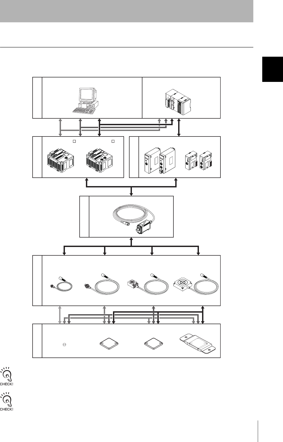
Product Configuration
A V680-series RFID System consists of an ID Controller, one or more Amplifiers, one or two Antennas, and
Tags. Select the models suitable for the application.
Using Antennas with Separate Amplifiers
When embedding the V680-D1KP52MT into a metal surface, use the V680-HS51, V680-HS52 Antenna.
Transmission will not be possible if the V680-HS63 Antenna is used.
Use the V680-D1KP52MT, V680-D1KP66T, V680-D1KP66MT, and V680-D1KP66T-SP ID Tags in combination with only the
V680-HA63A Amplifier, Do not use these ID Tags together with the V680-HA63B Amplifier.
V680-HA63A
Personal computer
V680-D1KP52MT
RS-232C
V680-D1KP66T V680-D1KP66MT
V680-HS63V680-HS51 V680-HS65V680-HS52
CS1W-V680C11/12
V680C11
RUN
ERC
T/R
NORM/ERR
ERP
ERH
TEST
ON
HEAD1
V680C12
RUN
ERC
HEAD1
T/R
NORM/ERR
ERP
ERH
HEAD2
T/R
NORM/ERR
TEST
ON
HEAD1
HEAD2
DC24V
INPUT
+
-
CJ1W-V680C11/12
RS-422 RS-485
Programmable Controller
(SYSMAC CS/CJ Series)
V680-D1KP66T-SP
Host device
ID Controller
Amplifiers
Antennas with Separate
Amplifier
Tags
ID Sensor Units
V680-CA5D01-VV680-CA5D02-V
16
Section 1 Product Configuration
RFID System
User's Manual
Section 1
Product Overview
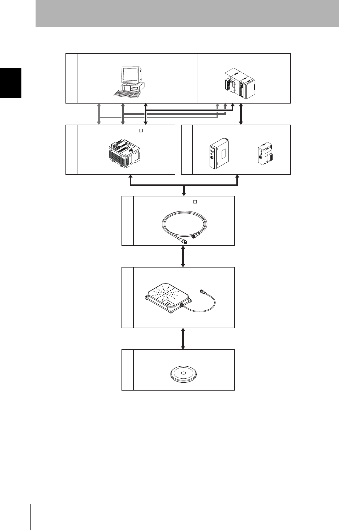
Using a V680-H01-V2 Antenna with Built-in Amplifier
RS-232C
CS1W-V680C11
V680C11
RUN
ERC
T/R
NORM/ERR
ERP
ERH
TEST
ON
HEAD1
CJ1W-V680C11
RS-422 RS-485
V680-H01-V2
V680-D1KP58HT
* Always use the specified Cable to connect a
V680-H01-V2 Antenna. The V680-H01-V2
Antenna cannot be connected without using
the specified Cable.
Host device
Programmable Controller
(SYSMAC CS/CJ Series)
ID Controller
ID Sensor Units
Cable
Antennas with Built-in
Amplifier
Tags
V700-A40-WM
V680-CA5D01-V
Personal computer

Section 2 Specifications and Performance
17
RFID System
User's Manual
Section 2
Specifications and Performance
Antennas with Separate Amplifier 18
Antennas with Built-in Amplifier 25
Amplifier 30
Tags 33
18
Section 2 Antennas with Separate Amplifier
RFID System
User's Manual
Section 2
Specifications and Performance
Antennas with Separate Amplifier
V680-HS51
General Specifications
Dimensions
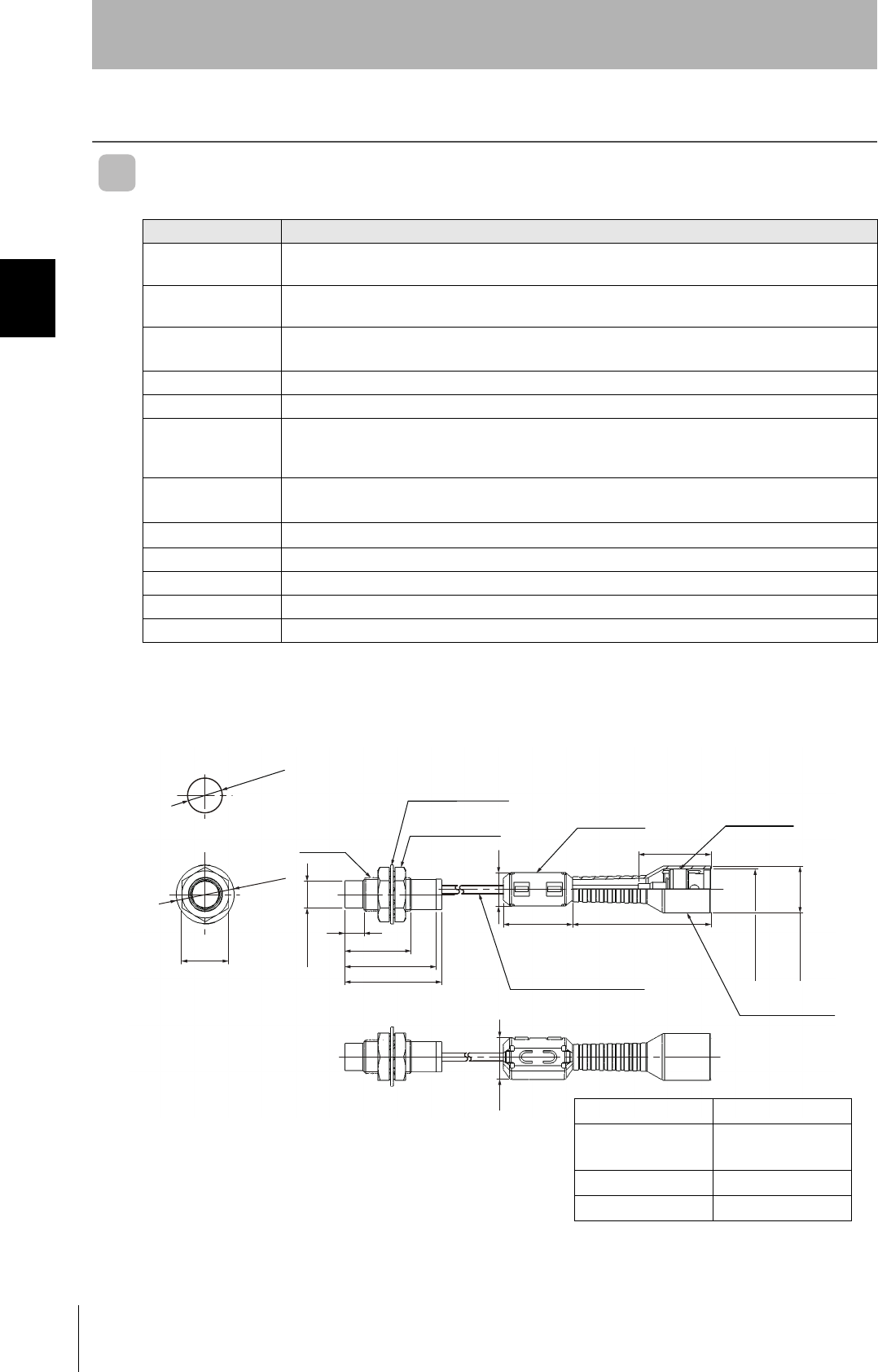
• V680-HS51
Item Model V680-HS51
Ambient operating
temperature
−10 to 60°C (with no icing)
Ambient storage
temperature
−25 to 75°C (with no icing)
Ambient operating
humidity
35% to 95% (with no condensation)
Insulation resistance 20 MΩ min. (at 500 VDC) between connector terminals and case
Dielectric strength 1,000 VAC, 50/60 Hz for 1 min between connector terminals and case
Degree of protection IP67.(IEC60529)
In-house standard for antenna oil resistance (former JEM standard equivalent to IP67g)
Note: The connectors are not waterproof.
Dielectric strength 10 to 2,000 Hz, 1.5-mm double amplitude, acceleration: 150 m/s2, 10 sweeps in each of 3 axis direc-
tions (up/down, left/right, and forward/backward) for 15 minutes each
Shock resistance 1,000 m/s2, 3 times each in 6 directions (Total: 18 times)
Dimensions M12 × 35 mm
Material ABS resin, brass, and epoxy resin filler
Weight Approx. 55 g
Cable length Standard lengths of 2 m
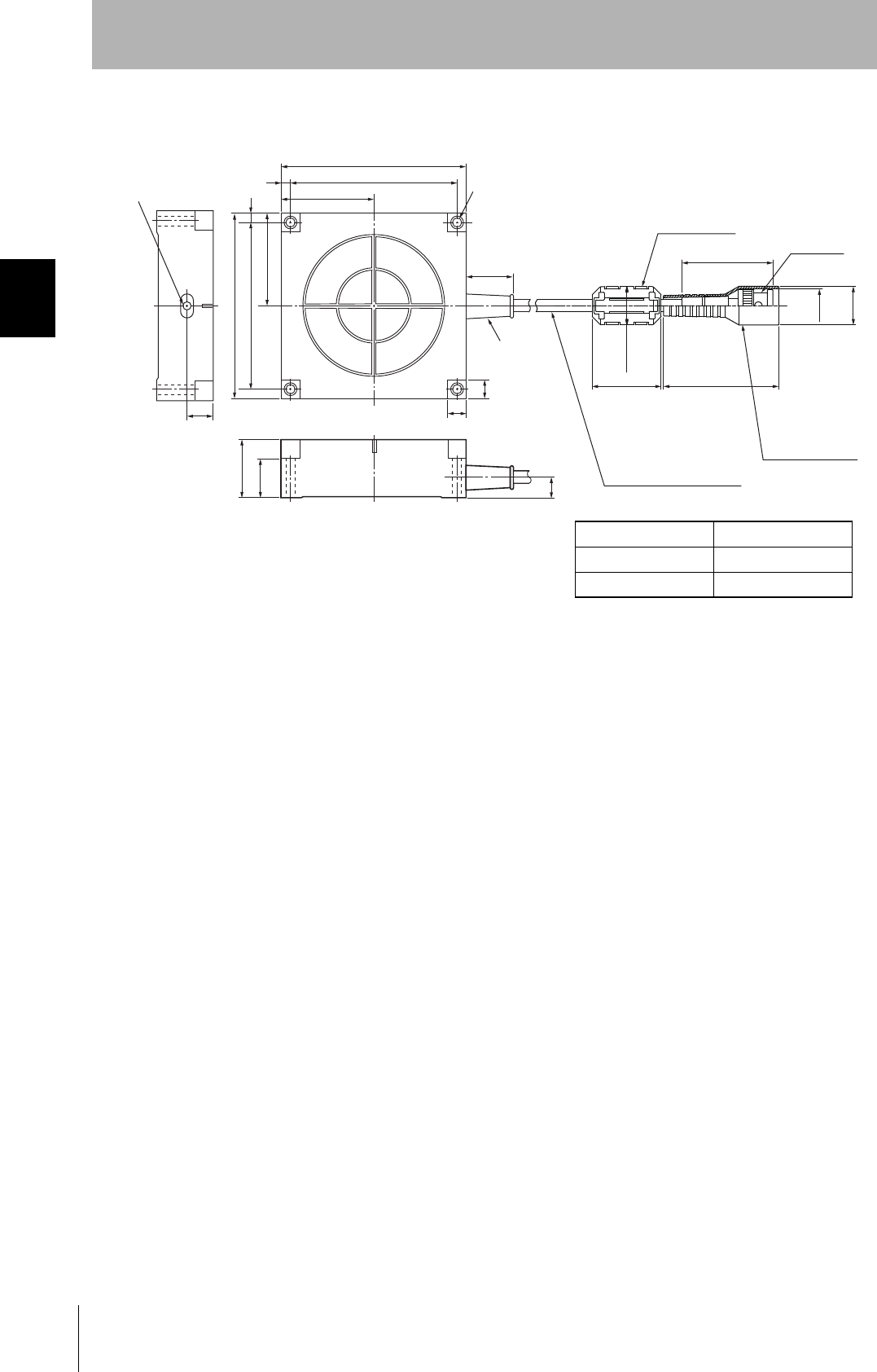
21 dia.
17
12.5 dia.
Mounting Hole Dimensions
(16.8 dia.)
(14.5 dia.)
7
24
33
35
12
25 50
26.2
9.6 dia.
M12 × 1
Toothed washer
Two lock nuts Ferrite core
Insulation cover
Connector
Coaxial cable, 2.9 dia.,
standard length: 2 m
15
(Unit : mm)
Case material Brass
Communications
surface
ABS resin
Fill resin Epoxy resin
Cable PVC (black)
19
RFID System
User's Manual
Section 2 Antennas with Separate Amplifier
Section 2
Specifications and Performance
V680-HS52
General Specifications
Dimensions
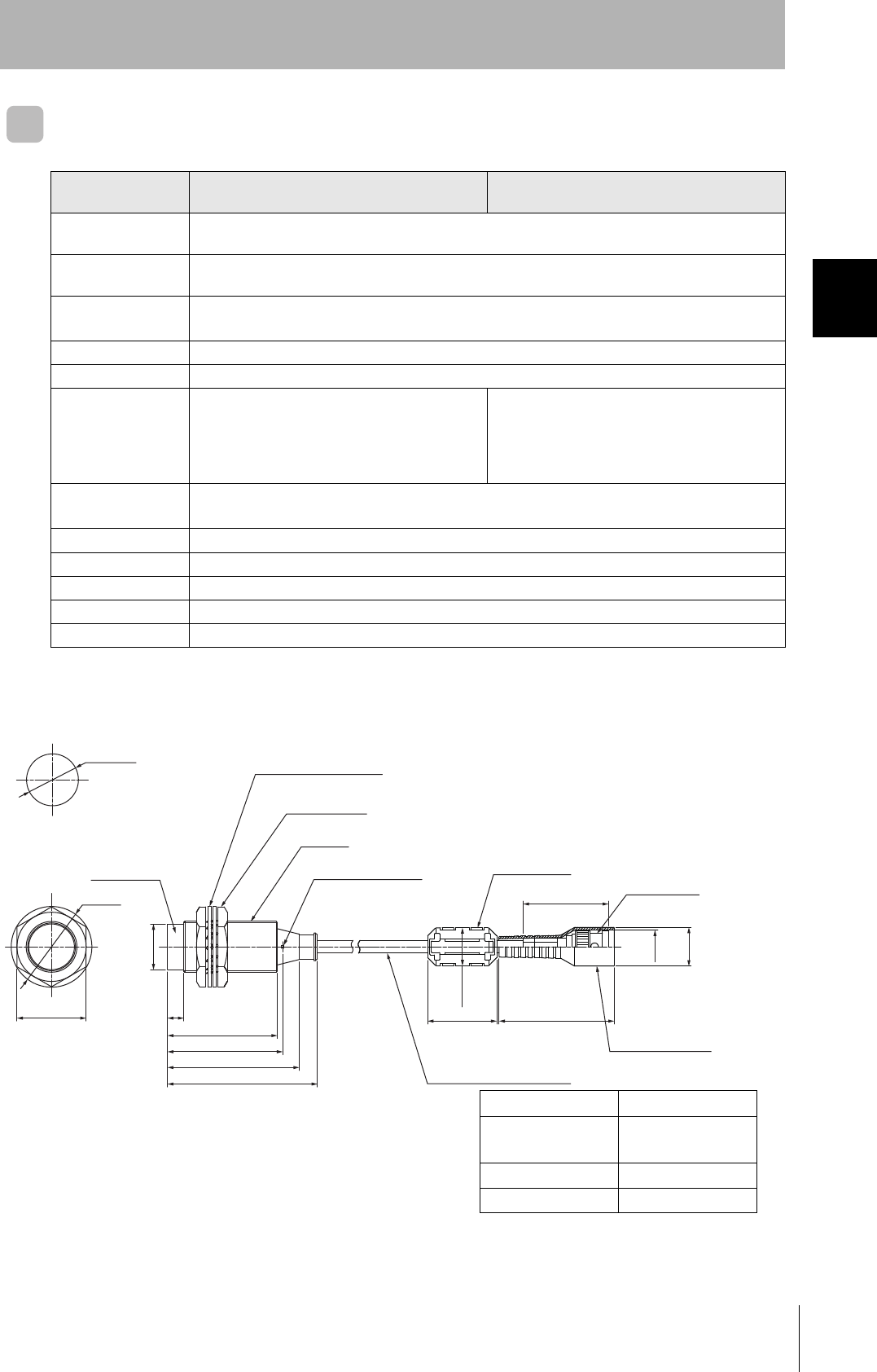
• V680-HS52-W
Item Model V680-HS52-W
(Standard cable, waterproof connector)
V680-HS52-R
(Flexible cable, non-waterproof connector)
Ambient operating
temperature
−10 to 60°C (with no icing)
Ambient storage
temperature
−25 to 75°C (with no icing)
Ambient operating
humidity
35% to 95% (with no condensation)
Insulation resistance 20 MΩ min. (at 500 VDC) between connector terminals and case
Dielectric strength 1,000 VAC, 50/60 Hz for 1 min between connector terminals and case
Degree of protection IP67.(IEC60529)
In-house standard for antenna oil resistance
(former JEM standard equivalent to IP67g)
Note: The connector specifications are IP67 and
IP65.(IEC60529)
IP67.(IEC60529)
In-house standard for antenna oil resistance
(former JEM standard equivalent to IP67g)
Note: The connectors are not waterproof.
Dielectric strength 10 to 500 Hz, 1.5-mm double amplitude, acceleration: 100 m/s2, 10 sweeps in each of 3 axis directions
(up/down, left/right, and forward/backward) for 8 minutes each
Shock resistance 500 m/s2, 3 times each in 6 directions (Total: 18 times)
Dimensions M22 × 65 mm
Material ABS resin, brass, and epoxy resin filler
Weight Approx. 850 g (with 12.5 m cable)
Cable length Standard lengths of 2 and 12.5 m
65
47.6
57
50
730
19.8 dia.
35 dia.
22.5 dia.
Mounting Hole Dimensions
Two toothed washers
Two lock nuts
M22 × 1
Operation indicator
37
5030
16.5 dia.
Coaxial cable, 5.5 dia.,
standard length: 2 m
Connector
Ferrite core
Insulation cover
16.5 dia.
14.5 dia.
Antenna
Case material Brass
Communications
surface
ABS resin
Fill resin Epoxy resin
Cable PVC (gray)
20
Section 2 Antennas with Separate Amplifier
RFID System
User's Manual
Section 2
Specifications and Performance
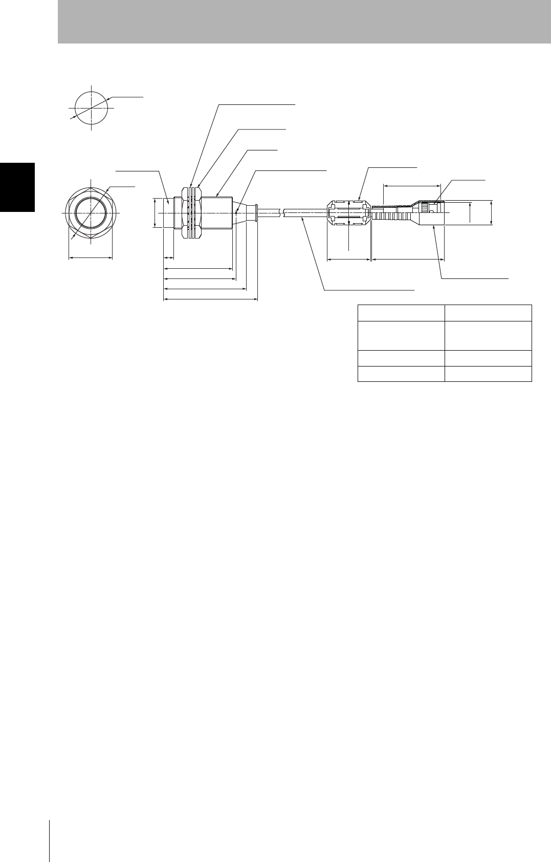
• V680-HS52-R
65
47.6
57
50
730
19.8 dia.
35 dia.
22.5 dia.
Mounting Hole Dimensions
Two toothed washers
Two lock nuts
M22 × 1
Operation indicator Insulation cover
5030
16.5 dia.
Coaxial cable, 5.3 dia.,
standard length: 2 m
Insulation cover
(39.5) Connector
Ferrite core
16.5 dia.
14.5 dia.
Antenna
Case material Brass
Communications
surface
ABS resin
Fill resin Epoxy resin
Cable PVC (black)

21
RFID System
User's Manual
Section 2 Antennas with Separate Amplifier
Section 2
Specifications and Performance
V680-HS63
General Specifications
Dimensions
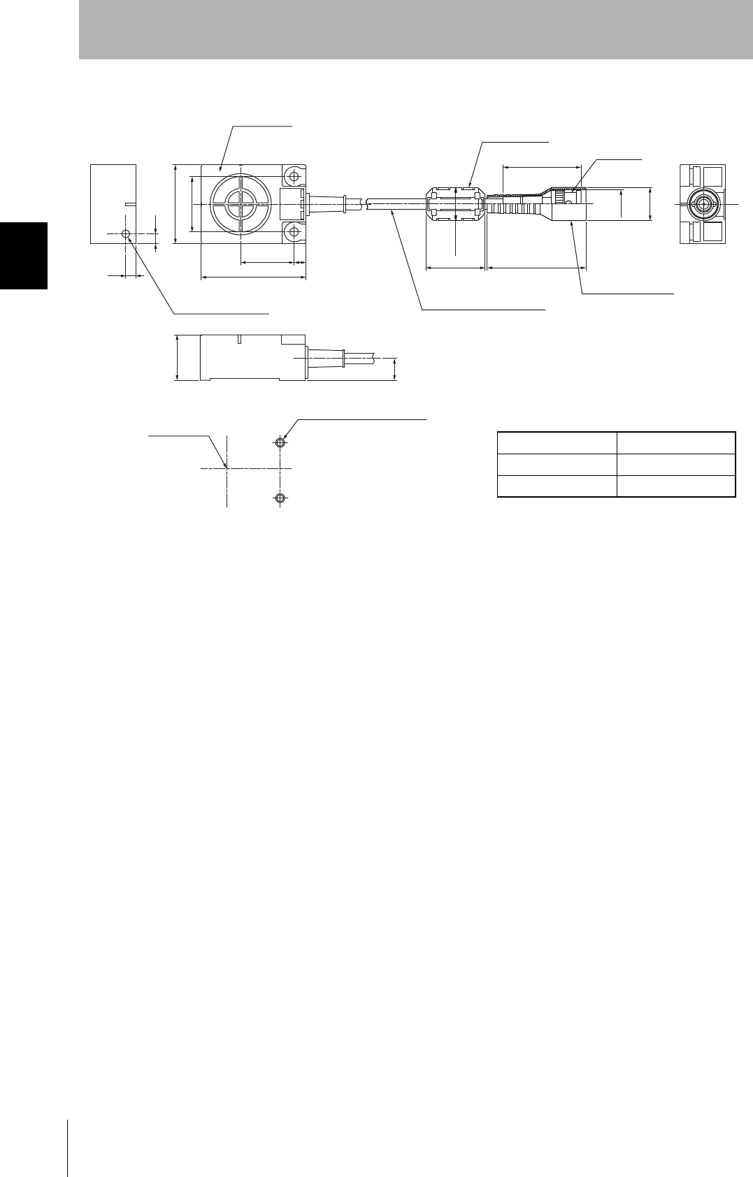
• V680-HS63-W
Item Model V680-HS63-W
(Standard cable, waterproof connector)
V680-HS63-R
(Flexible cable, non-waterproof connector)
Ambient operating
temperature
−10 to 60°C (with no icing)
Ambient storage
temperature
−25 to 75°C (with no icing)
Ambient operating
humidity
35% to 95% (with no condensation)
Insulation resistance 20 MΩ min. (at 500 VDC) between cable terminals and case
Dielectric strength 1,000 VAC, 50/60Hz for 1 min between cable terminals and case
Degree of protection IP67.(IEC60529)
In-house standard for antenna oil resistance
(former JEM standard equivalent to IP67g)
Note: The connector specifications are IP67 and
IP65.(IEC60529)
IP67.(IEC60529)
In-house standard for antenna oil resistance
(former JEM standard equivalent to IP67g)
Note: The connectors are not waterproof.
Vibration resistance 10 to 500 Hz, 1.5-mm double amplitude, acceleration: 100 m/s2, 10 sweeps in each of 3 axis directions
(up/down, left/right, and forward/backward) for 11 minutes each
Shock resistance 500 m/s2, 3 times each in 6 directions (Total: 18 times)
Dimensions 40 × 53 × 23 mm
Material ABS resin case, epoxy resin filler
Weight Approx. 850 g (with 12.5 m cable)
Cable length Standard lengths of 2 and 12.5 m
(Unit: mm)
23
5
5
Operation indicator
40
28±0.1
53
27 6
11
Note: Mounting Hole Dimensions
Coil center
Two, M4 or 4.5 dia. holes
37
5030
16.5 dia.
Coaxial cable, 5.5 dia.,
standard length: 2 m
Connector
Ferrite core
Insulation cover
16.5 dia.
14.5 dia.
Antenna
Case material ABS resin
Fill resin Epoxy resin
Cable PVC (gray)
22
Section 2 Antennas with Separate Amplifier
RFID System
User's Manual
Section 2
Specifications and Performance
V680-HS63-R
Antenna
23
5
5
40
28±0.1
53
27 6
11
(Unit: mm)
Operation indicator
Note: Mounting Hole Dimensions
Coil center
Two, M4 or 4.5 dia. holes
5030
16.5 dia.
Coaxial cable, 5.3 dia.,
standard length: 2 m
Insulation cover
(39.5) Connector
Ferrite core
16.5 dia.
14.5 dia.
Case material ABS resin
Fill resin Epoxy resin
Cable PVC (black)

23
RFID System
User's Manual
Section 2 Antennas with Separate Amplifier
Section 2
Specifications and Performance
V680-HS65
General Specifications
Dimensions
• V680-HS65-W
Item Model V680-HS65-W
(Standard cable, waterproof connector)
V680-HS65-R
(Flexible cable, non-waterproof connector)
Ambient operating
temperature
−25 to 70°C (with no icing)
Ambient storage
temperature
−40 to 85°C (with no icing)
Ambient operating
humidity
35% to 95% (with no condensation)
Insulation resistance 20 MΩ min. (at 500 VDC) between connector terminals and case
Dielectric strength 1,000 VAC, 50/60 Hz for 1 min between connector terminals and case
Degree of protection IP67 (IEC60529)
In-house standard for antenna oil resistance
(former JEM standard equivalent to IP67g)
Note: The connector specifications are IP67 and
IP65 (IEC 60529).
IP67 (IEC60529)
In-house standard for antenna oil resistance
(former JEM standard equivalent to IP67g)
Note: The connectors are not waterproof.
Dielectric strength 10 to 500 Hz, 1.5-mm double amplitude, acceleration: 100 m/s2, 10 sweeps in each of 3 axis directions
(up/down, left/right, and forward/backward) for 11 minutes each
Shock resistance 500 m/s2, 3 times each in 6 directions (Total: 18 times)
Dimensions 100 × 100 × 30 mm
Material ABS resin case, epoxy resin filler
Weight Approx. 1100 g (with 12.5 m cable)
Cable length Standard lengths of 2 and 12.5 m
Operation indicator
30
20
11
(Unit: mm)
16.5 dia.
14.5 dia.
37
5030
16.5 dia.
Coaxial cable, 5.5 dia.,
standard length: 2 m
Connector
Ferrite core
Insulation cover
14 10
10
Bushing
50
25
100
90±0.25
50
100
90±0.2 5
4-4.5 dia.
(Mounting holes)
Case material ABS resin
Fill resin Epoxy resin
Cable PVC (gray)
24
Section 2 Antennas with Separate Amplifier
RFID System
User's Manual
Section 2
Specifications and Performance
V680-HS65-R
(39.5)
16.5 dia.
14.5 dia.
(Unit: mm)
5030
16.5 dia.
Coaxial cable, 5.3 dia.,
standard length: 2 m
Insulation cover
Connector
Ferrite core
Operation indicator
30
20
11
14 10
10
Bushing
50
25
100
90±0.25
50
100
90±0.2 5
4-4.5 dia.
(Mounting holes)
Case material ABS resin
Fill resin Epoxy resin
Cable PVC (black)
25
RFID System
User's Manual
Section 2 Antennas with Built-in Amplifier
Section 2
Specifications and Performance
Antennas with Built-in Amplifier
V680-H01-V2
General Specifications
Communications Specifications
Item Model V680-H01-V2
Ambient operating
temperature
−10 to 55°C (with no icing)
Ambient storage
temperature
−35 to 65°C (with no icing)
Ambient operating
humidity
35% to 85% (with no condensation)
Insulation resistance 20 MΩ min. (at 100 VDC) between connector terminals and the rear plate
Dielectric strength 1,000 VAC, 50/60 Hz for 1 min between connector terminals and the rear plate
Degree of protection IP63.(IEC60529); Mounting direction: Communications surface facing up
Dielectric strength 10 to 150 Hz, 0.35-mm single amplitude, acceleration: 50 m/s2, 10 sweeps in each of 3 axis directions
(up/down, left/right, and forward/backward) for 8 minutes each
Shock resistance 150 m/s2, 3 times each in 6 directions (Total: 18 times)
Cable length 0.5 m (use an extension cable to connect to the Controller up to 30.5 m)
LED indicators RUN, COMM, NORM, ERR, CNT-TYPE, TAG-TYPE, Error Code, Level
Weight Approx. 900 g
Item Model V680-H01-V2
Communications method Electromagnetic induction
Operating frequency 13.56 MHz ± 7KHz
Modulation ASK
26
Section 2 Antennas with Built-in Amplifier
RFID System
User's Manual
Section 2
Specifications and Performance
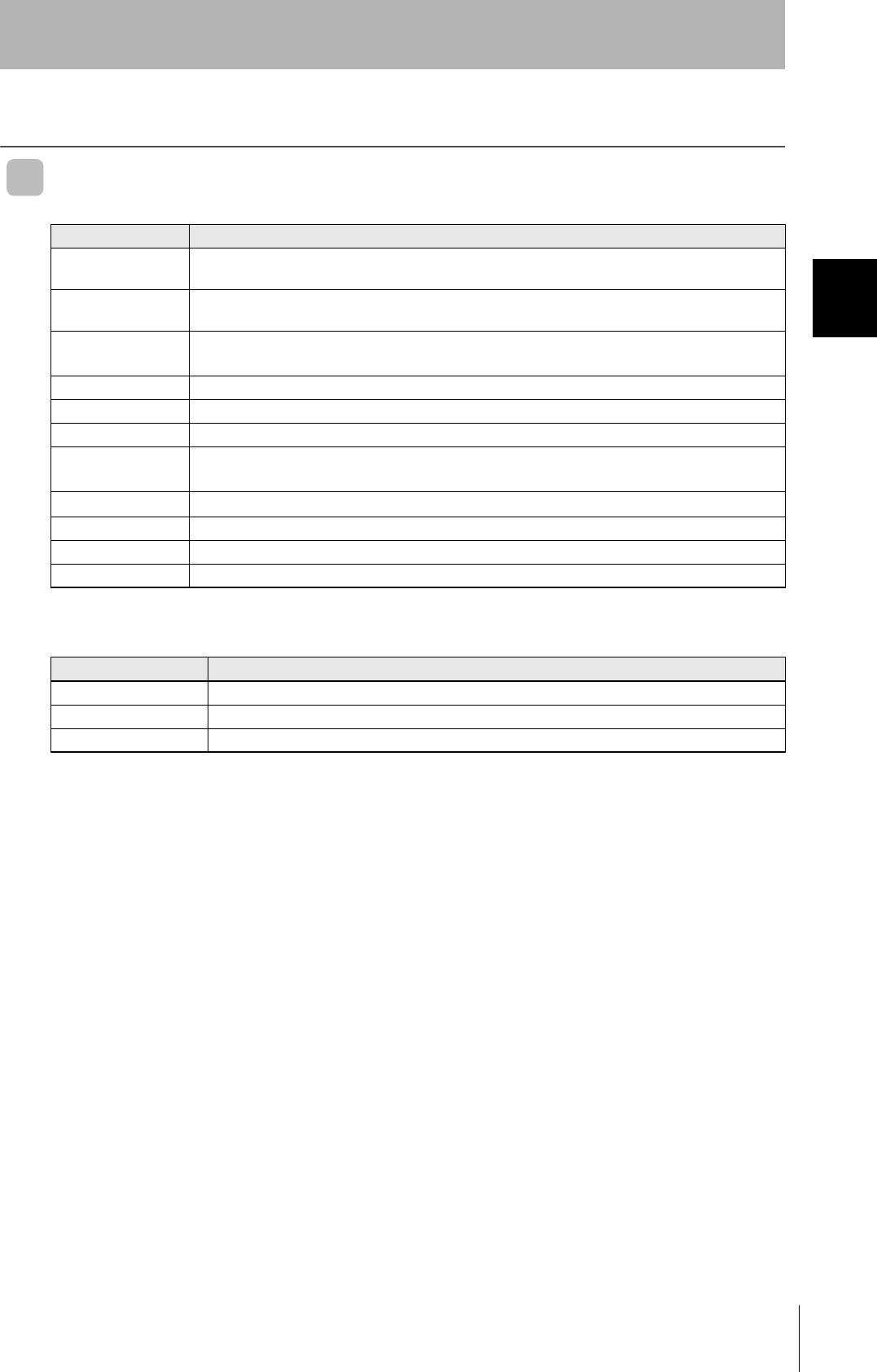
Dimensions
Senter of Coil
185±0.2
Four, M4 or 4.5-dia. holes
142.5
235±0.2
65
(25-dia.)
Setting switch protection Cover
50 6
30 38
142.5
235
250
7.5
500 0 (45)
+50
(17)
14 64.8
20-dia.
200
185
Four, 5-dia. holes
(Mounting Holes)
Ferrite Core
Connector
Vinyl Insulated Round Cord (5.8-dia.)
(41/0.16-dia.) 2 Cores (17/0.08-dia.) 8 Cores
Standard Length 0.5 m
Twelve, Operation Indicator
13.5
(1)40
(Unit : mm)
Four, Mounting bracket
MOUNTING SCREW HOLES
Communications sufrace
Case material PC/ASA resin
Rear Panel Aluminum
Cable PVC
27
RFID System
User's Manual
Section 2 Antennas with Built-in Amplifier
Section 2
Specifications and Performance
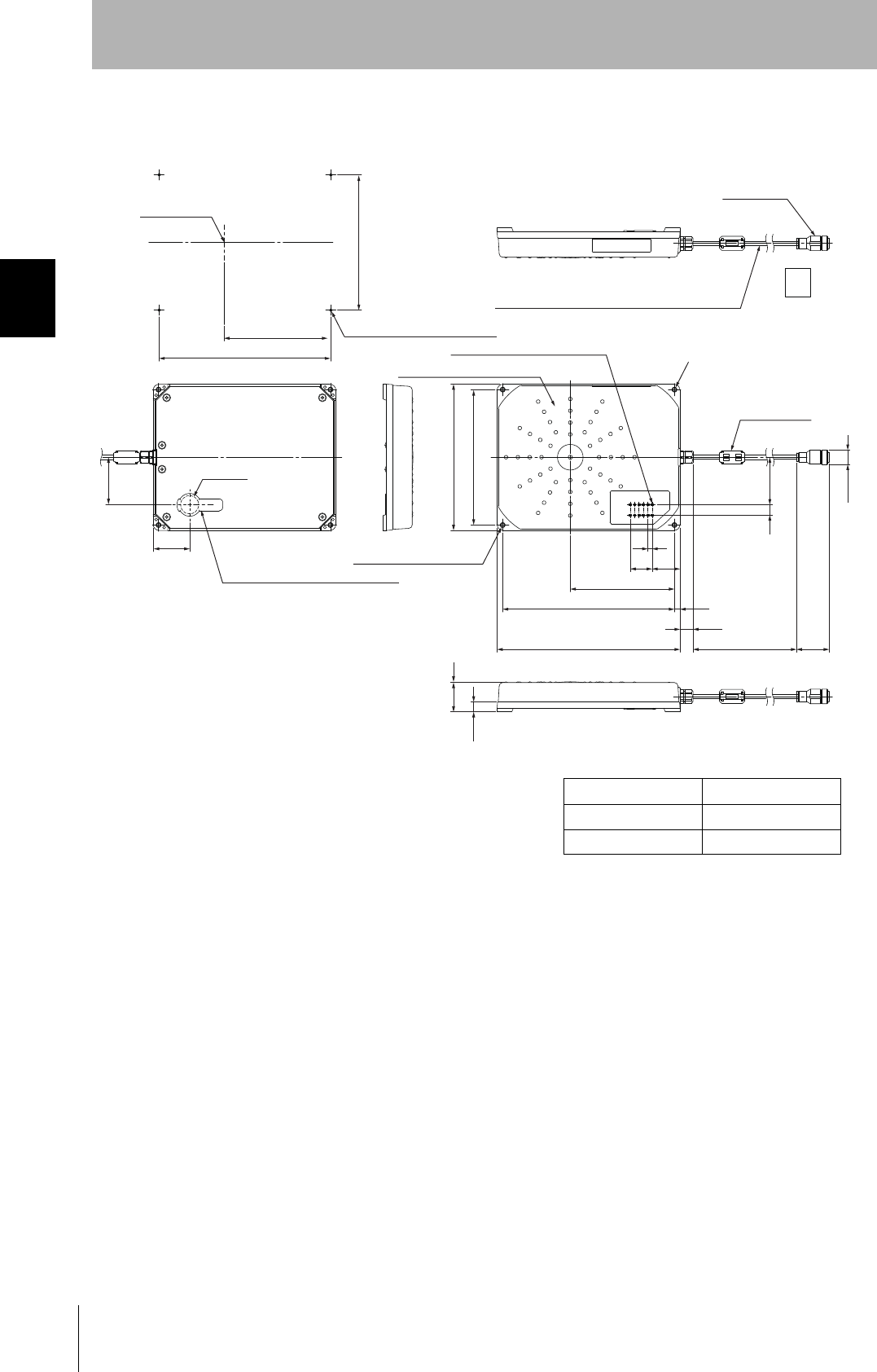
Operation Indicator
The distance level will vary greatly depending on the surrounding environment. The setting position will serve as a
guide, but use RUN mode to conduct a sufficient number of tests in the actual operating environment.
Values of distance level 4 or above may not be displayed, but this will not affect the RUN mode performance and does
not indicate a malfunction.
Differences between the V680-H01 and the V680-H01-V2
As shown in the following table, the V680-H01-V2 provides additional indicators.
Turn ON SW1-1(Antenna) when using the V680-CA1D/CA2D.
name Color Meaning
RUN Green Lit when the power is ON.
COMM Yellow Lit when a command is being sent.
NORM Green Lit when communications with a Tag are normal in Normal Communications Mode.
ERR Red Lit when an error occurs in communications with a Tag in Normal Communications
Mode.
CNT-TYPE Yellow Lit when in V680-CA@D Controller connection mode (SW1-1 setting: ON).
TAG-TYPE Yellow For expansion (not used): Always OFF.
LV6/7D Yellow Maintenance Mode: Lit at distance or speed level 6.
Normal Communications Mode: Lit when a write protection error occurs.
LV5/7A Yellow Maintenance Mode: Lit at distance or speed level 5 or higher.
Normal Communications Mode: Lit when an address error occurs.
LV4/76 Yellow Maintenance Mode: Lit at distance or speed level 4 or higher.
Normal Communications Mode: Lit when a Tag memory error occurs.
LV3/72 Yellow Maintenance Mode: Lit at distance or speed level 3 or higher.
Normal Communications Mode: Lit when a no Tag error occurs.
LV2/71 Yellow Maintenance Mode: Lit at distance or speed level 2 or higher.
Normal Communications Mode: Lit when a verification error occurs.
LV1/70 Yellow Maintenance Mode: Lit at distance or speed level 1 or higher.
Normal Communications Mode: Lit when a Tag communications error occurs.
display functions V680-H01-V2 V680-H01
SW1-1: OFF SW1-1: ON no switch
RUN (POWER/COMM) OK OK OK
COMM (POWER/COMM) OK OK OK
NORM OK NO NO
ERR OK NO NO
CNT-TYPE OK OK NO
TAG-TYPE --- --- ---
LV6/7D OK NO NO
LV5/7A OK NO NO
LV4/76 OK NO NO
LV3/72 OK NO NO
LV2/71 OK NO NO
LV1/70 OK NO NO
28
Section 2 Antennas with Built-in Amplifier
RFID System
User's Manual
Section 2
Specifications and Performance
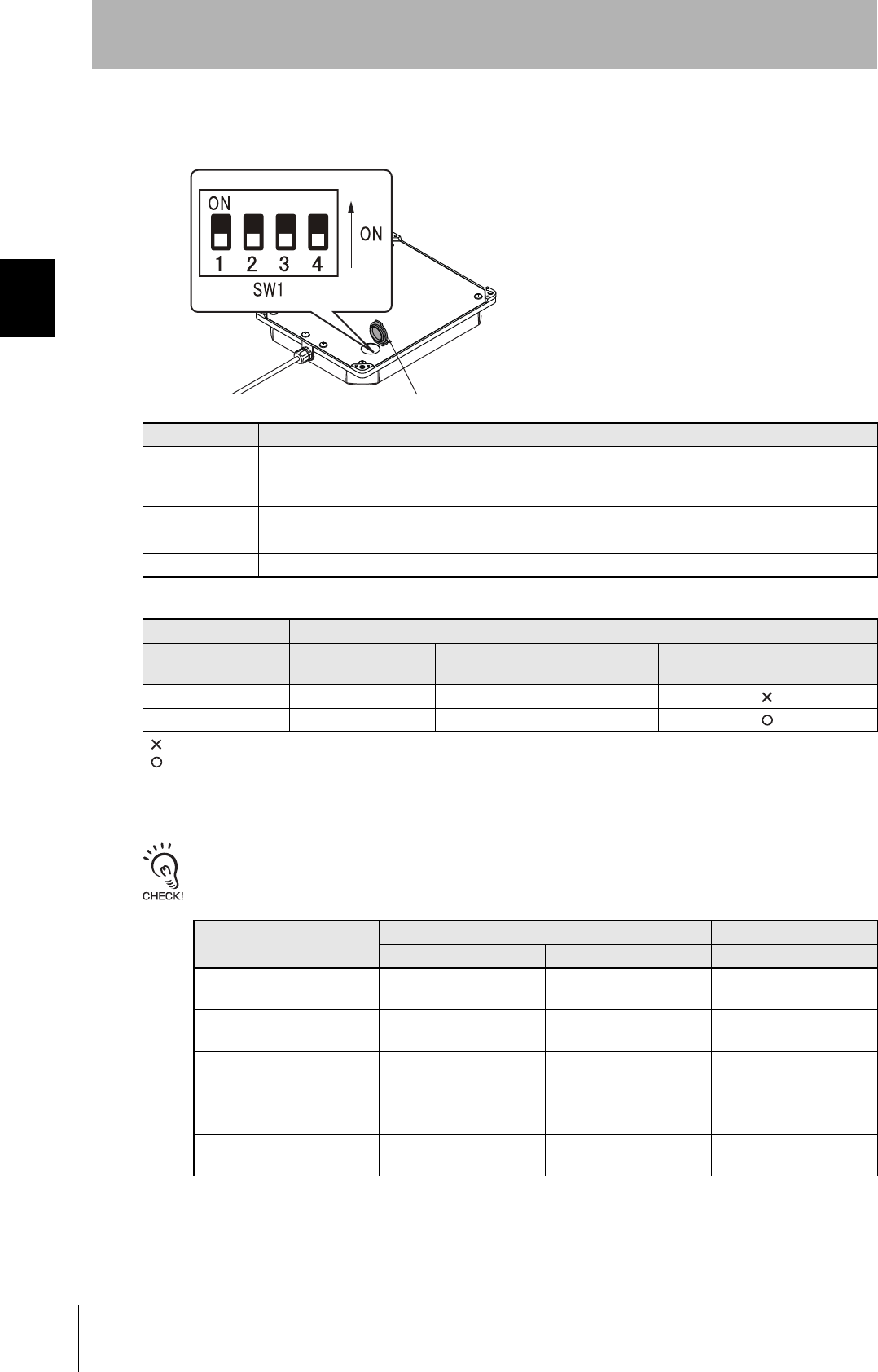
Setting Switch
Set SW1-1 on the V680-H01-V2 Antenna and the Controller as shown in the following table.
Differences between the V680-H01 and the V680-H01-V2
As shown in the following table, the V680-H01-V2 supports additional maintenance functions.
Turn ON SW1-1(Antenna) when using the V680-CA1D/CA2D.
Setting Function Default setting
SW1-1 Controller selection
OFF:V680-CA5D01-V@, CS1W-V680C11, or CJ1W-V680C11
ON: V680-CA1D/-CA2D
OFF
SW1-2 Reserved by System (Always set this Switch to OFF.) ---
SW1-3 Reserved by System (Always set this Switch to OFF.) ---
SW1-4 Reserved by System (Always set this Switch to OFF.) ---
Antenna setting Controller setting
V680-H01-V2 V680-CA5D01-V@CS1W-V680C11
CJ1W-V680C11
V680-CA1D
V680-CA2D
SW1-1: OFF SW4-8: OFF DM20000 + 100 × m+3=0000
SW1-1: ON SW4-8: ON See Note. DM20000 + 100 × m+3=0001 See Note. See Note.
: Cannot be used.
: Can be used.(Controller setting not required.)
Note: The high-speed mode cannot be used by the controller's setting.
display functions V680-H01-V2 V680-H01
SW1-1: OFF SW1-1: ON no switch
Communication Test Mode OK OK OK
Noise Level Measurement
Mode
OK NO NO
Distance Level Measurement
Mode
OK NO NO
Speed Level Measurement
Mode
OK NO NO
Communications Success
Rate Measurement Mode
OK NO NO
Setting switch protection cover
Note: Please attach a setting switch protection cover after setting switch.
29
RFID System
User's Manual
Section 2 Antennas with Built-in Amplifier
Section 2
Specifications and Performance
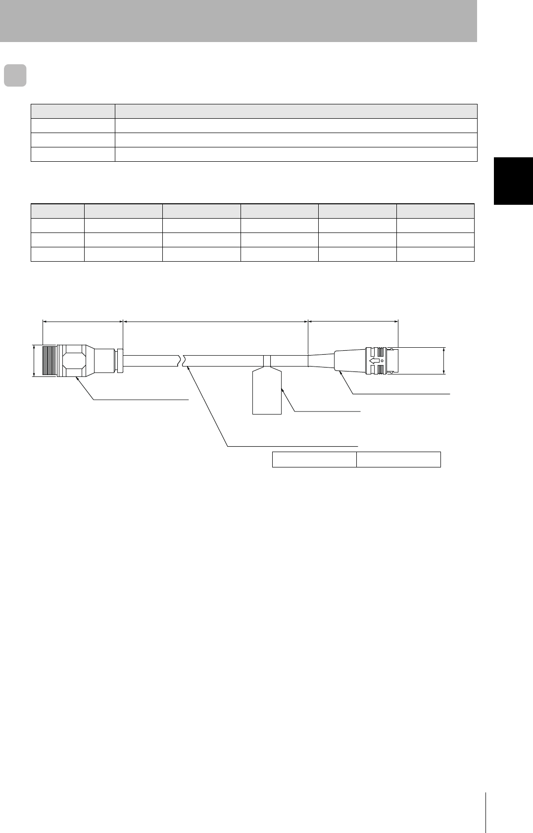
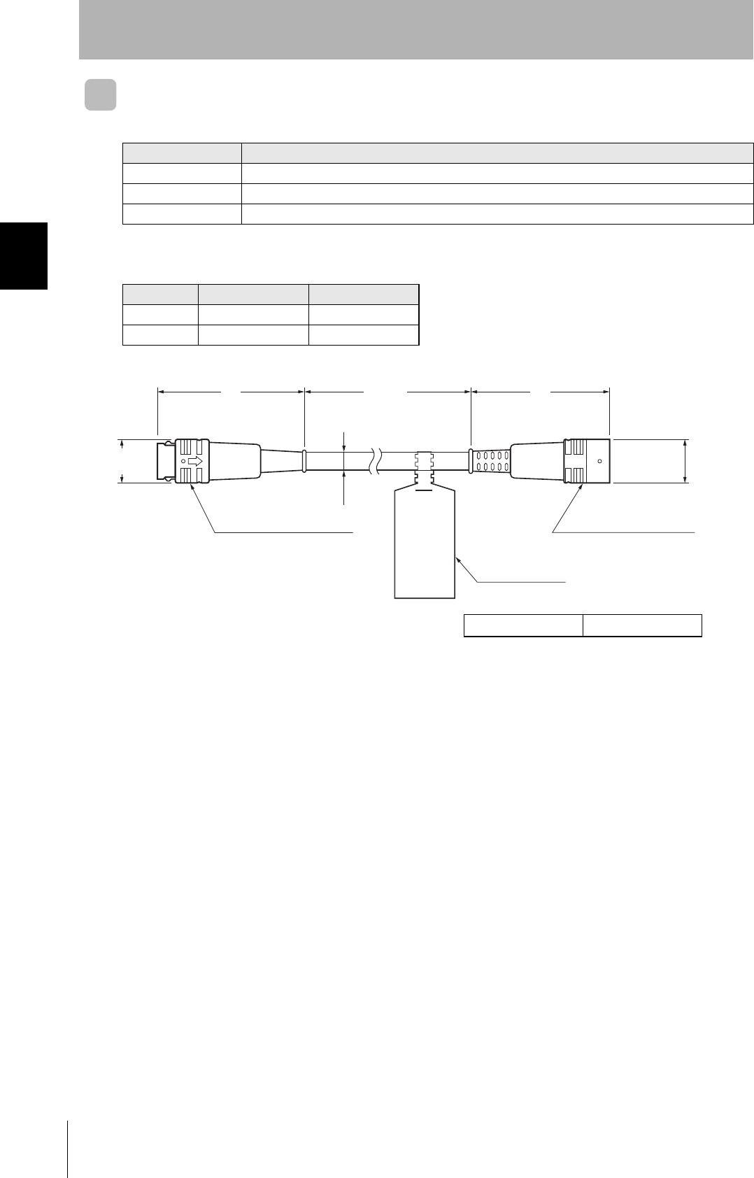
Cables (V680-H01-V2 exclusive use)
Specifications
Dimensions
Item Model V700-A40-W
Number of conductors 10
Insulation resistance 5 MΩ min. (at 500 VDC) between terminals and sheath
Dielectric strength 500 VAC, 1 min
Item Model V700-A40-W 2M V700-A40-W 5M V700-A40-W 10M V700-A40-W 20M V700-A40-W 30M
Length (L1) Approx.2m Approx. 5 m Approx.10m Approx. 20 m Approx. 30 m
Weight Approx. 150 g Approx.360 g Approx. 700 g Approx.1,350 g Approx.2,000 g
L1 2,000 5,000 10,000 20,000 30,000
Connector (Antenna end)) Connector (Controller end))
Connection label
Vinyl Insulated Round Cord
6 dia.
20 dia.
41.8L1
±100
49
(Unit: mm)
15 dia.
Cable PVC
30
Section 2 Amplifier
RFID System
User's Manual
Section 2
Specifications and Performance
Amplifier
V680-HA63A
General Specifications
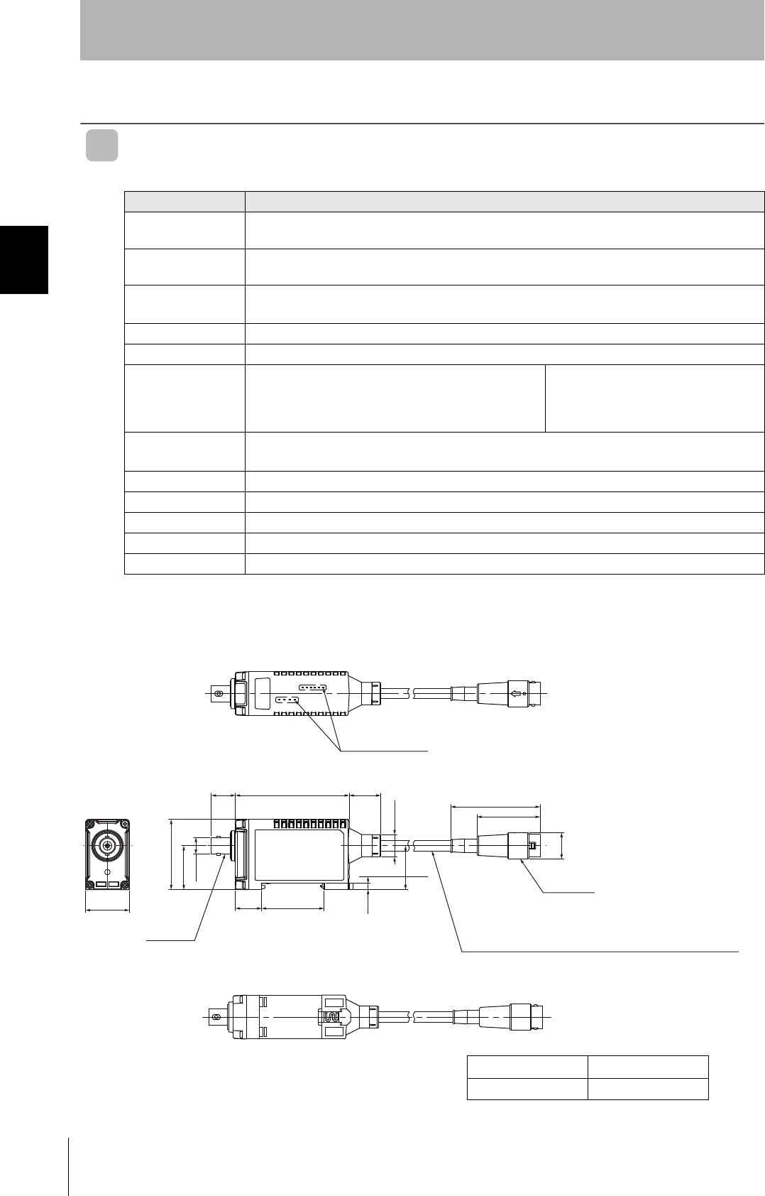
Dimensions
Item Model V680-HA63A
Ambient operating
temperature
−10 to 55°C (with no icing)
Ambient storage
temperature
−25 to 65°C (with no icing)
Ambient operating
humidity
35% to 85% (with no condensation)
Insulation resistance 20 MΩ min. (at 500 VDC) between cable terminals and case
Dielectric strength 1,000 VAC, 50/60 Hz for 1 minute between cable terminals and case.
Degree of protection IP67, IP65 (IEC 60529)
Note: Not including connector at Controller end.
(When V680-HS52-W, V680-HS63-W, and V680-HS65-W
is connected)
IP40 (IEC 60529)
(When V680-HS51, V680-HS52-R, V680-
HS63-R, and V680-HS65-R is connected)
Dielectric strength 10 to 500 Hz, 1.5-mm double amplitude, acceleration:100 m/s2, 10 sweeps in each of 3 axis directions
(up/down, left/right, and forward/backward) for 11 minutes each
Shock resistance 500 m/s2, 3 times each in 6 directions (Total: 18 times)
Dimensions 25 × 40 × 65 mm (Not including protrusions.)
Materials PC
Weight Approx. 650 g (with 10 m cable)
Cable length Standard lengths of 5 and 10 m
Note: The maximum total cable extension is 50 m (including the Amplifier cable). A maximum of two extension cables can be
connected.
Operation indicator
13.7 65 18
51
36
15 dia.
40
25
9.5 dia.
25
3.5
12.8 dia.
15 35.6
25
Round, vinyl-insulated cable (5.8 dia.), standard length: 5 m,
(41/0.16 dia) 2 conductors, (17/0.08 dia.) 8 conductors
Connector
Connector
Case material PC resin
Cable PVC
31
RFID System
User's Manual
Section 2 Amplifier
Section 2
Specifications and Performance
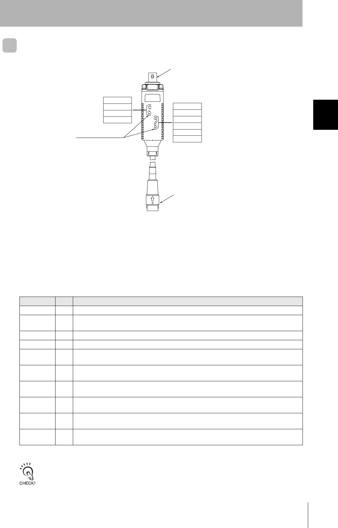
Nomenclature
Antenna Connection Port
The Antenna connection port is connected a V680-series Antenna.
Controller Connector
The Controller connector is connected to Antenna connection port on the Controller.
Operation Indicators (LEDs)
The distance level will vary greatly depending on the surrounding environment. The setting position will serve as a
guide, but use RUN mode to conduct a sufficient number of tests in the actual operating environment.
Values of distance level 4 or above may not be displayed, but this will not affect the RUN mode performance and does
not indicate a malfunction.
Name Color Meaning
RUN Green Lit when the power is ON.
COMM Yel-
low
Lit when a command is being sent.
NORM Green Lit when communications with a Tag are normal in Normal Communications Mode.
ERR Red Lit when an error occurs in communications with a Tag in Normal Communications Mode.
LV6/7D Yel-
low
Maintenance Mode: Lit at distance or speed level 6.
Normal Communications Mode: Lit when a write protection error occurs.
LV5/7A Yel-
low
Maintenance Mode: Lit at distance or speed level 5 or higher.
Normal Communications Mode: Lit when an address error occurs.
LV4/76 Yel-
low
Maintenance Mode: Lit at distance or speed level 4 or higher.
Normal Communications Mode: Lit when a Tag memory error occurs.
LV3/72 Yel-
low
Maintenance Mode: Lit at distance or speed level 3 or higher.
Normal Communications Mode: Lit when a no Tag error occurs.
LV2/71 Yel-
low
Maintenance Mode: Lit at distance or speed level 2 or higher.
Normal Communications Mode: Lit when a verification error occurs.
LV1/70 Yel-
low
Maintenance Mode: Lit at distance or speed level 1 or higher.
Normal Communications Mode: Lit when a Tag communications error occurs.
Operation indicators
RUN
COMM
NORM
ERR
LV6/7D
LV5/7A
LV4/76
LV3/72
LV2/71
LV1/70
Antenna with Separate Amplifier connection port
Controller connector
32
Section 2 Amplifier
RFID System
User's Manual
Section 2
Specifications and Performance
Cables (V680-HA63 exclusive use)
Specifications
Dimensions
Item Model V700-A43/V700-A44
Number of conductors 10
Insulation resistance 5 MΩ min. (at 500 VDC) between terminals and sheath
Dielectric strength 500 VAC, 1 min
Item Model V700-A43 V700-A44
Length (L1) Approx.10m Approx. 20 m
Weight Approx. 700 g Approx.1,350 g
51 L1
±100
49
15.5 dia.
Connector (Controller end))
Connection label
Connector (Amplifier end)
6 dia.
15 dia.
(Unit: mm)
Cable PVC
33
RFID System
User's Manual
Section 2 Tags
Section 2
Specifications and Performance
Tags
Specifications and Dimensions
V680-D1KP52MT
• General Specifications
Note: After string data at high temperatures, rewrite the data even if changes are not required, In this manual, high
temperatures are those exceeding 125°C up to 180°C.
• Dimensions
When embedding the V680-D1KP52MT into a metal surface, use the V680-HS51, V680-HS52 Antenna.
Transmission will not be possible if the V680-HS63 Antenna is used.
The side with the markings is the communications surface. Mount the Tag with this side facing the Antenna.
The ID code is written in the memory of the Tag and may be affected by data retention characteristics at high tempera-
tures. Take suitable precautions when using the READ ID command for Tags operating at high temperatures.
Item Model V680-D1KP52MT
Memory capacity 1,000 bytes (user area)
Memory type EEPROM
Data backup time 10 years after writing (85°C or less), 0.5 years after writing (85°C to 125°C)
Total data backup time at high temperatures exceeding 125°C is 10 houres (See note.)
Memory longevity 100,000 times per block (25°C)
Ambient operating
temperature
−25 to 85°C (with no icing)
Ambient storage
temperature
−40 to 125°C (with no icing)
Ambient operating
humidity
35% to 95%
Degree of protection IP68 (IEC 60529)
In-house standard for antenna oil resistance (former JEM standard equivalent to IP67g)
Vibration resistance 10 to 2,000 Hz, 1.5-mm double amplitude, acceleration: 150 m/s2, 10 sweeps each in X, Y, and Z
directions for 15 minutes each
Shock resistance 500 m/s2, 3 times each in X, Y, and Z directions (Total: 18 times)
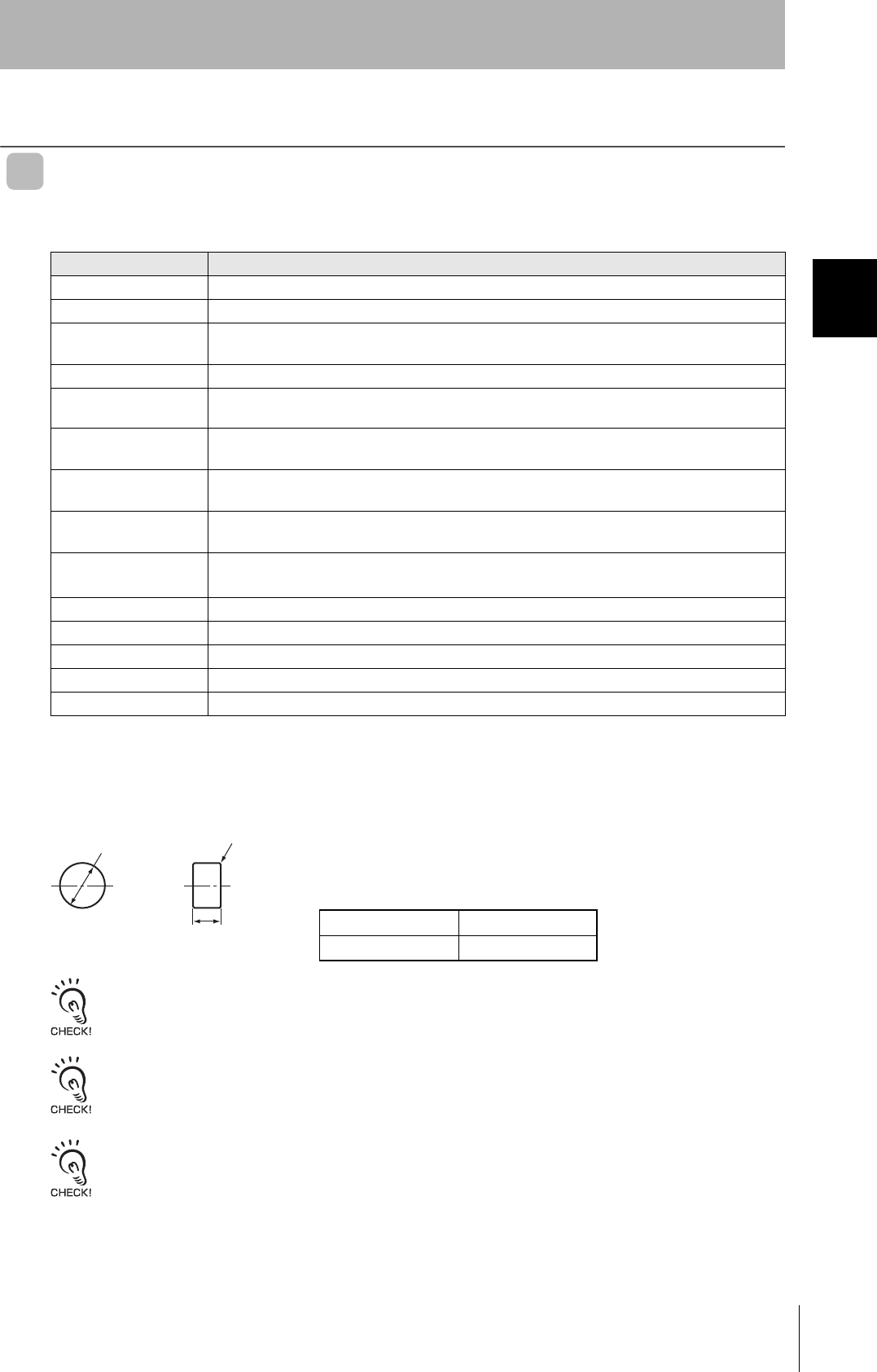
Dimensions 8 dia. × 5 mm
Materials Case: PPS resin, Fill resin: Epoxy resin
Weight Approx. 0.5 g
Metal countermeasures Yes
8
0
−0.1
R0.2
5
0
−0.1
dia.
(Unit : mm)
Case material PPS resin
Fill resin Epoxy resin
34
Section 2 Tags
RFID System
User's Manual
Section 2
Specifications and Performance
V680-D1KP66T/66MT
• General Specifications
Note: After string data at high temperatures, rewrite the data even if changes are not required, In this manual, high
temperatures are those exceeding 125°C up to 180°C.
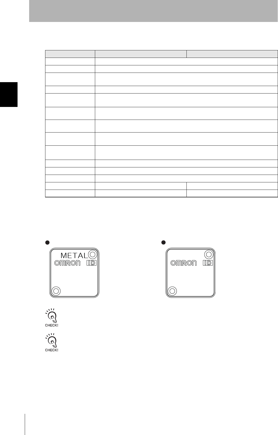
The V680-D1KP66MT is designed to be mounted directly to metal. The V680-D1KP66T and V680-
D1KP66MT markings are shown in the following diagrams.
The side with the markings is the communications surface. Mount the Tag with this side facing the Antenna.
The ID code is written in the memory of the Tag and may be affected by data retention characteristics at high tempera-
tures. Take suitable precautions when using the READ ID command for Tags operating at high temperatures.
Item Model V680-D1KP66T V680-D1KP66MT
Memory capacity 1,000 bytes (user area)
Memory type EEPROM
Data backup time 10 years after writing (85°C or less), 0.5 years after writing (85°C to 125°C)
Total data backup time at high temperatures exceeding 125°C is 10 houres (See note.)
Memory longevity 100,000 times per block (25°C)
Ambient operating
temperature
−25 to 85°C (with no icing)
Ambient storage
temperature
−40 to 125°C (with no icing)
Ambient operating
humidity
35% to 95%
Degree of protection IP68 (IEC 60529)
In-house standard for antenna oil resistance (former JEM standard equivalent to IP67g)
Vibration resistance 10 to 2,000 Hz, 1.5-mm double amplitude, acceleration: 150 m/s2,10 sweeps each in X, Y, and Z
directions for 15 minutes each
Shock resistance 500 m/s2, 3 times each in X, Y, and Z directions (Total: 18 times)
Dimensions 34 × 34 × 3.5 mm
Materials Case: PPS resin
Weight Approx. 6 g Approx. 7.5 g
Metal countermeasures None Yes
V680-D1KP66MT V680-D1KP66T
MADE IN JAPAN
XXXXXX
V680-D1KP66MT
MADE IN JAPAN
XXXXXX
V680-D1KP66T
35
RFID System
User's Manual
Section 2 Tags
Section 2
Specifications and Performance
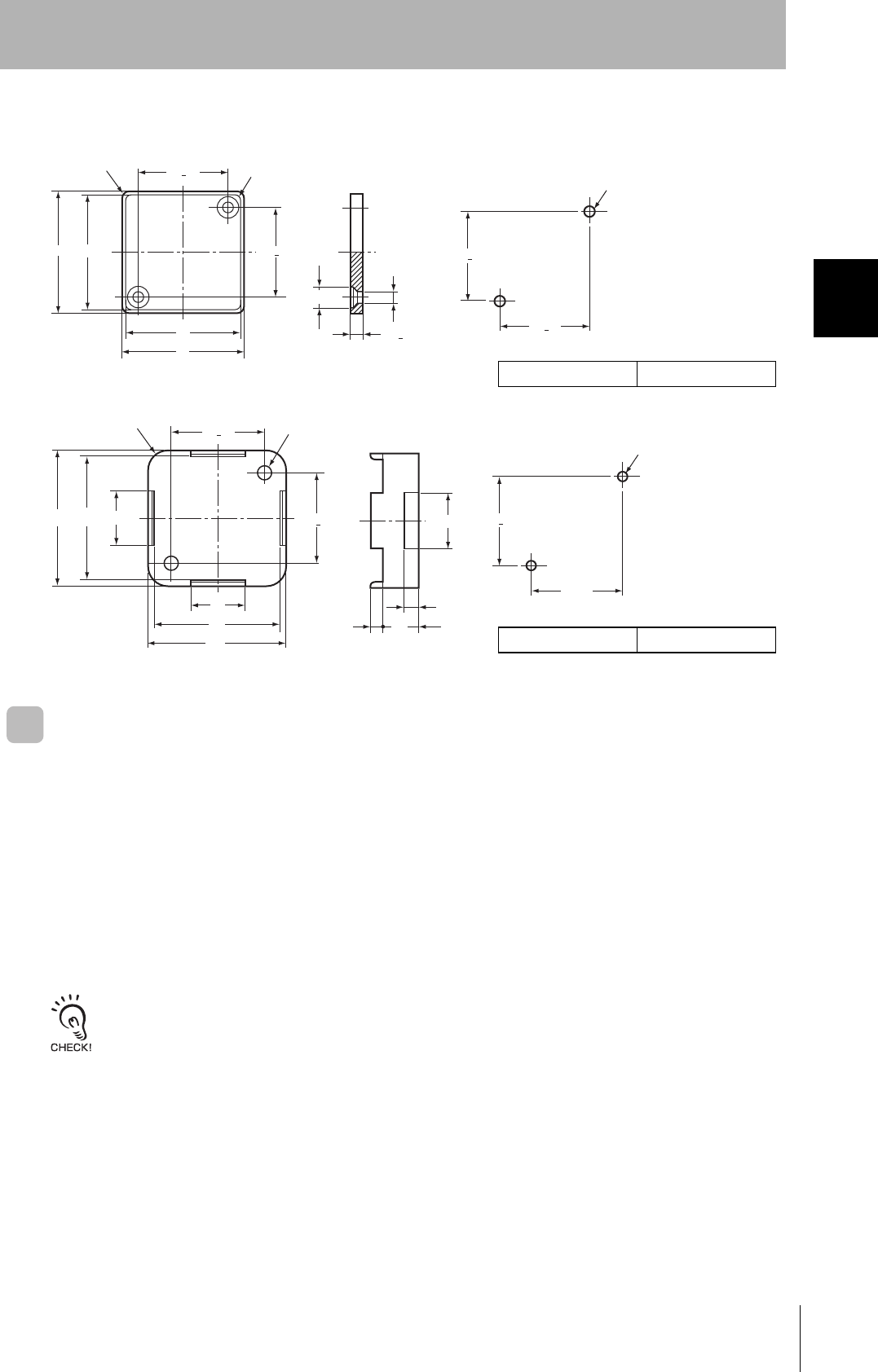
• Dimensions
V680-D1KP66T/66MT
V600-A86 Attachment
Tag Heat Resistivity
• Storing Tags under high temperatures will adversely affect the performance of the internal parts and
the service life of the Tags.
• An LTPD of 10% was determined during the evaluation for Tags that reached the end of their life after
testing under the following test conditions.
LTPD: Lot tolerance percent defective
The lower limit of the malfunction rate for lots to be considered unacceptable during reliability testing.
Heat cycle −10°C/+150°C, 30 minutes each for 1,000 cycles
−100°C/+180°C,30 minutes each for 200 cycles
High temperatures +150°C, 1,000 hours
+180°C, 200 hours
25+0.2
25+0.2
25+0.2
25+0.2
3.5+0.1
Two, M3
Four, R3
Four, R4
32
32
34
34
Mounting Hole Dimensions
Two, 3.5 dia.
Two, 6 dia.
Case material PPS resin
25+0.2
25+0.2
25+0.2
25+0.2 16
4
10
3.5
37
37
34
34
15
15
Two, M3
Two, 4 dia.
Four, R5.5
Case material PPS resin
36
Section 2 Tags
RFID System
User's Manual
Section 2
Specifications and Performance
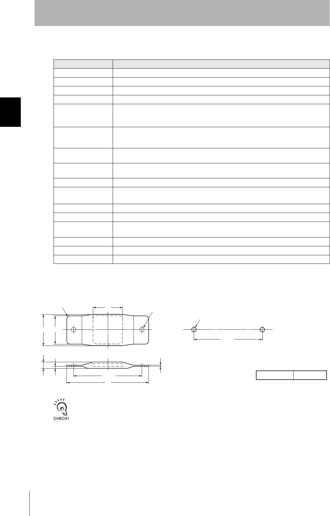
V680-D1KP66T-SP
• General Specifications
• Dimensions
The side with the markings is the communications surface. Mount the Tag with this side facing the Antenna.
Item Model V680-D1KP66T-SP
Memory capacity 1,000 bytes (user area)
Memory type EEPROM
Data backup time 10 years after writing (85°C or less)
Memory longevity 100,000 times per block (25°C)
Ambient operating
temperature when
communicating
−25 to 70°C (with no icing)
Ambient operating
temperature when not
communicating
−40 to110°C (with no icing)
Ambient storage
temperature
−40 to 110°C (with no icing)
Ambient operating
humidity
35% to 95%
Degree of protection IP67
Vibration resistance 10 to 2,000 Hz, 1.5-mm double amplitude, acceleration: 150 m/s2,10 sweeps each in X, Y, and Z
directions for 15 minutes each
Shock resistance 500 m/s2, 3 times each in X, Y, and Z directions (Total: 18 times)
Dimensions 95 × 36.5 × 6.5 mm (excluding protruding parts)
Materials External coatiog: Fluororesin (PFA)
Tag body: PPS resin
Weight Approx. 20 g
Mounting method Two M5 screws
Metal countermeasures None
Two, 5.5 dia.
(Mounting hole)
Four, R6
1.3
6.5 2.5 max.
Two, M5
80±0.2
80±0.2
34
95
3436.5
Mounting Hole Dimensions
PFA resinCase material
(Unit: mm)
37
RFID System
User's Manual
Section 2 Tags
Section 2
Specifications and Performance
V680-D1KP58HT
• General Specifications
Note: After string data at high temperatures, rewrite the data even if changes are not required, In this manual, high
temperatures are those exceeding 110°C up to 200°C.
The maximum operating temperature during communication is 85°C. The temperature of the actual Tag must not be
higher than 85°C when the Tag enters the Antenna's communications area. When using a Tag after storage at high tem-
perature, perform tests before use, and make sure that the temperature of the Tag does not exceed 85°C during opera-
tion.
Item Model V680-D1KP58HT
Memory capacity 1,000 bytes (user area)
Memory type EEPROM
Data backup time 10 years after writing (85°C or less), 2 years after writing (85°C to 110°C)
Total data backup time at high temperatures exceeding 110°C is 10 houres (See note.)
Memory longevity 100,000 times per block (25°C)
Ambient operating
temperature
−10 to 85°C (with no icing)
Ambient storage
temperature
−40 to 110°C (with no icing)
Degree of protection IP67 (IEC 60529)
Vibration resistance 10 to 2,000 Hz, 1.5-mm double amplitude, acceleration: 150 m/s2,10 sweeps each in X, Y, and Z
directions for 15 minutes each
Shock resistance 500 m/s2, 3 times each in X, Y, and Z directions (Total: 18 times)
Materials Coatiog: PPS resin
Weight Approx. 90 g
38
Section 2 Tags
RFID System
User's Manual
Section 2
Specifications and Performance
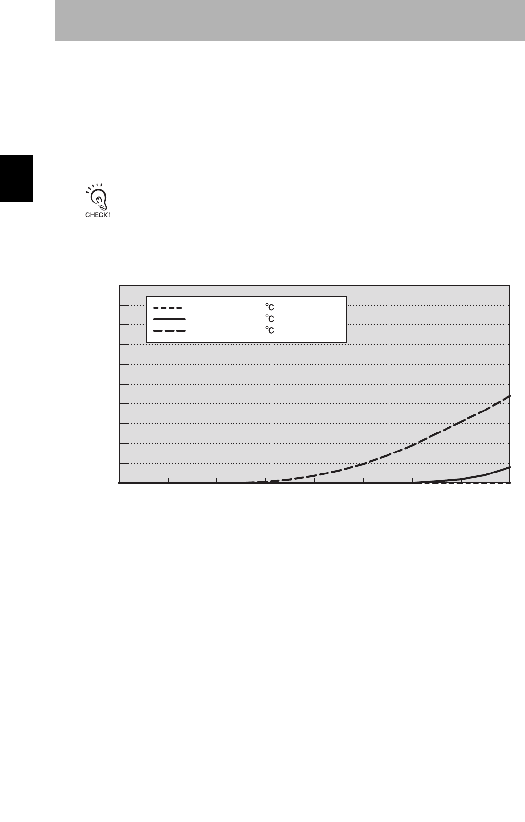
• Tag Heat Resistivity
• Storing Tags under high temperatures will adversely affect the performance of the internal parts and
the service life of the Tags.
• An LTPD of 10% was determined during the evaluation for Tags that reached the end of their life after
testing under the following test conditions
• Heat cycle: Room temperature/200ÅãC, 30 minutes each for 2,000 cycles.
• Normal operation has been confirmed after performing the above tests, although minor cracks may
occur.
LTPD: Lot tolerance percent defective
The lower limit of the malfunction rate for lots to be considered unacceptable during reliability testing.
• Reference Data (Evaluation Test Results)
Room temp. / 180
0 500 1000 1500 2000 2500 3000 3500 4000
10%
9%
8%
7%
6%
5%
4%
3%
2%
1%
0%
Number of cycles
Defective rate(%)
Heat Resistance Evaluation Results
Defective Operation
, 30min each
Room temp. / 200 , 30min each
Room temp. / 220 , 30min each
39
RFID System
User's Manual
Section 2 Tags
Section 2
Specifications and Performance
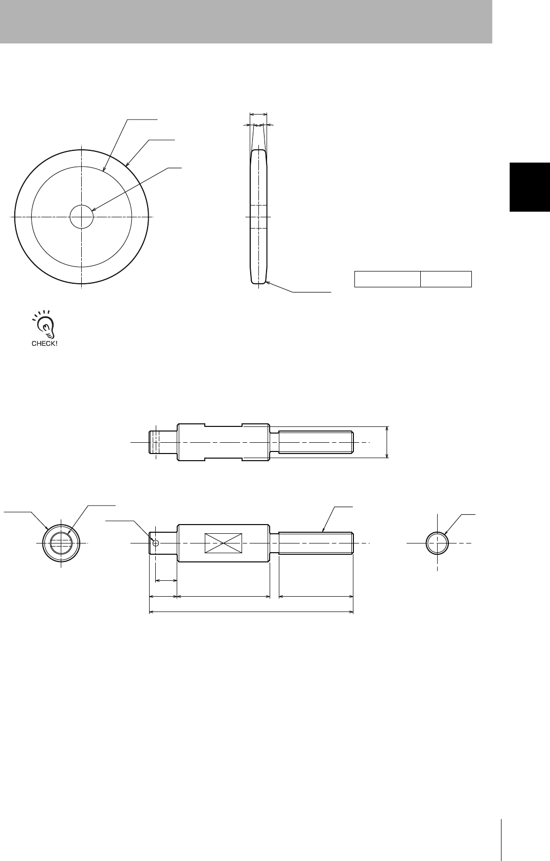
• Dimensions
V680-D1KP58HT
The side with the markings is the communications surface. Mount the Tag with this side facing the Antenna.
V680-A80 (Attachment)
This Attachment is specifically designed to secure V680-D1KP58HT Tags to the workpiece.
Applicable Tag model: V680-D1KP58HT
10±0.2
5°
14 dia
60 dia.
80 dia
Two, R2
5°
(Unit: mm)
Case material PPS resin
Mounting Hole Dimensions
20 dia. M12
M12
4050
11.5
15
110
3.2 dia.
12 dia.
17
2
1
Nuts (M12):
Provided Parts
Split pin (3.2 × 20 mm):
(Unit: mm)

40
Section 2 Tags
RFID System
User's Manual
Section 2
Specifications and Performance
Memory Map
EEPROM is used as memory in the Tags.
The memory capacity available to the user is 1,000 bytes, including 0000H to 0003H (the Write Protec-
tion Setting Area).
The access to the memory is executed at every block.
1 block is 8 bytes (8 addresses).
Address Data
0000 H
0001 H
0002 H
0003 H
1 byte
03E6 H
03E7 H
User area
41
RFID System
User's Manual
Section 2 Tags
Section 2
Specifications and Performance
Write Protection Function
The write protection function prevents important data, such as product information, stored in memory in
a Tag from being inadvertently overwritten.
After important data has been written to memory, it can be write-protected using the following method.
The write protection function can be switched with SW4-7 (Write Protection Function Setting) of the V680-CA5D@@-V@
Controller or with word (Write Protection Function Setting) in the DM(m+2)CH Area words allocated to the C@1W-
V680C@@ ID Sensor Unit.
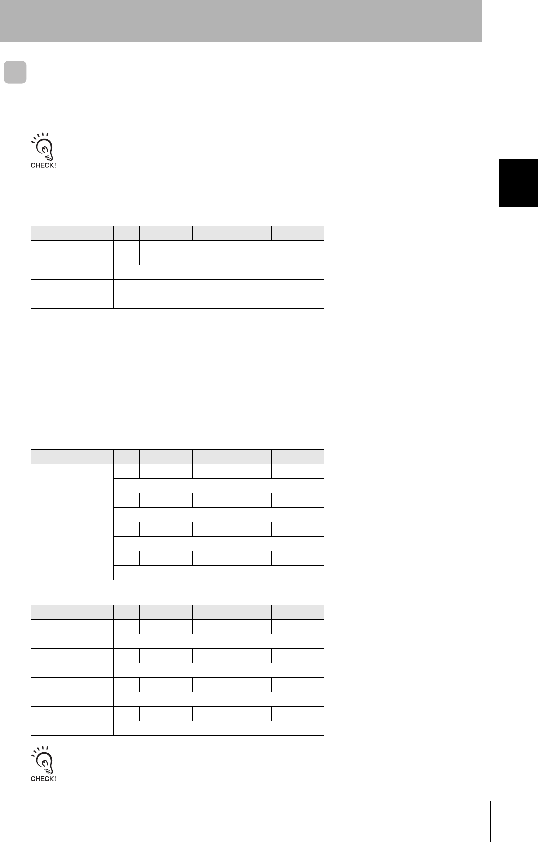
Setting the Write Protection Function
Write protection is set in Tag addresses 0000H to 0003H.
The setting for the most significant bit of address 0000H specifies whether or not write protection is enabled.
• Write-protect Bit (Most significant bit of address 0000H)
1: Write-protected (Yes)
0: Not write-protected (No)
• Write Protection Setting Area
Start address: 0000H to 7FFFH
End address: 0000H to FFFFH
Write Protection Setting Examples
• Settings to write-protect addresses 0008H through 03E7H:
• Settings to not write-protect any addresses:
The write protection function is a function of the V680-CA5D@@-V@ Controller and the C@1W-V680C@@ ID Sensor
Unit. It is not supported by reader/writer units from other manufacturers.
Address Bit 76543210
0000HYES/
NO Upper two digits of start address (00H to 7FH)
0001HLower two digits of start address (00H to FFH)
0002HUpper two digits of end address (00H to FFH)
0003HLower two digits of end address (00H to FFH)
Address Bit 76543210
0000H
10000000
80
0001H
00001000
08
0002H
00000011
03
0003H
11100111
E7
Address Bit 76543210
0000H
00000000
00
0001H
00000000
00
0002H
00000000
00
0003H
00000000
00

42
Section 2 Tags
RFID System
User's Manual
Section 2
Specifications and Performance
MEMO