Omron 6CYSIDV6800308 RFID System User Manual Z262 E1 04
Omron Corporation RFID System Z262 E1 04
Omron >
Contents
- 1. Manual 1
- 2. Manual 2
Manual 2

Section 3 Communications Specifications
43
RFID System
User's Manual
Section 3
Communications Specifications
Communications Distances 44
Communication Time (Reference) 53
44
Section 3 Communications Distances
RFID System
User's Manual
Section 3
Communications Specifications
Communications Distances
V680-D1KP52MT
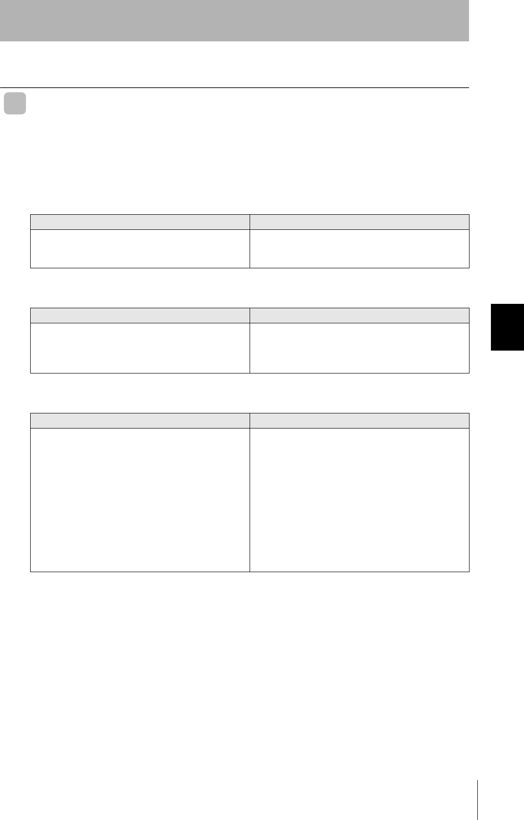
Communications Distance Specifications (Certified Performance)
When embedding the V680-D1KP52MT into a metal surface, use the V680-HS51, V680-HS52 Antenna.
Transmission will not be possible if the V680-HS63 Antenna is used.
• Measurement Conditions
Amplifier Antenna ID Tag Communications distance
V680-HA63A
V680-HS51 V680-D1KP52MT Read 0.5 to 6.5 mm (Axis offset: ±2 mm)
Write 0.5 to 6.0 mm (Axis offset: ±2 mm)
V680-HS51 V680-D1KP52MT embedded in
metal (steel)
Read 0.5 to 3.5 mm (Axis offset: ±2 mm)
Write 0.5 to 3.0 mm (Axis offset: ±2 mm)
V680-HS52 V680-D1KP52MT Read 0 to 9.0 mm (Axis offset: ±2 mm)
Write 0 to 8.5 mm (Axis offset: ±2 mm)
V680-HS52 V680-D1KP52MT embedded in
metal (steel)
Read 0 to 4.5 mm (Axis offset: ±2 mm)
Write 0 to 4.0 mm (Axis offset: ±2 mm)
V680-HS63 V680-D1KP52MT Read 0 to 12.0 mm (Axis offset: ±2 mm)
Write 0 to 9.5 mm (Axis offset: ±2 mm)
V680-HS52
Metal
V680-HS63
V680-D1KP52MT
V680-HS52
Non-metallic material
(Examples: Resin, plastic, wood, etc.)
Non-metallic material
V680-D1KP52MT
Metal
V680-HS51 V680-HS51
V680-D1KP52MT
Metal
V680-D1KP52MT
Non-metallic materialNon-metallic material
Metal
V680-D1KP52MT
Non-metallic material
(Examples: Resin, plastic, wood, etc.)
Non-metallic material
(Examples: Resin, plastic, wood, etc.)
45
RFID System
User's Manual
Section 3 Communications Distances
Section 3
Communications Specifications
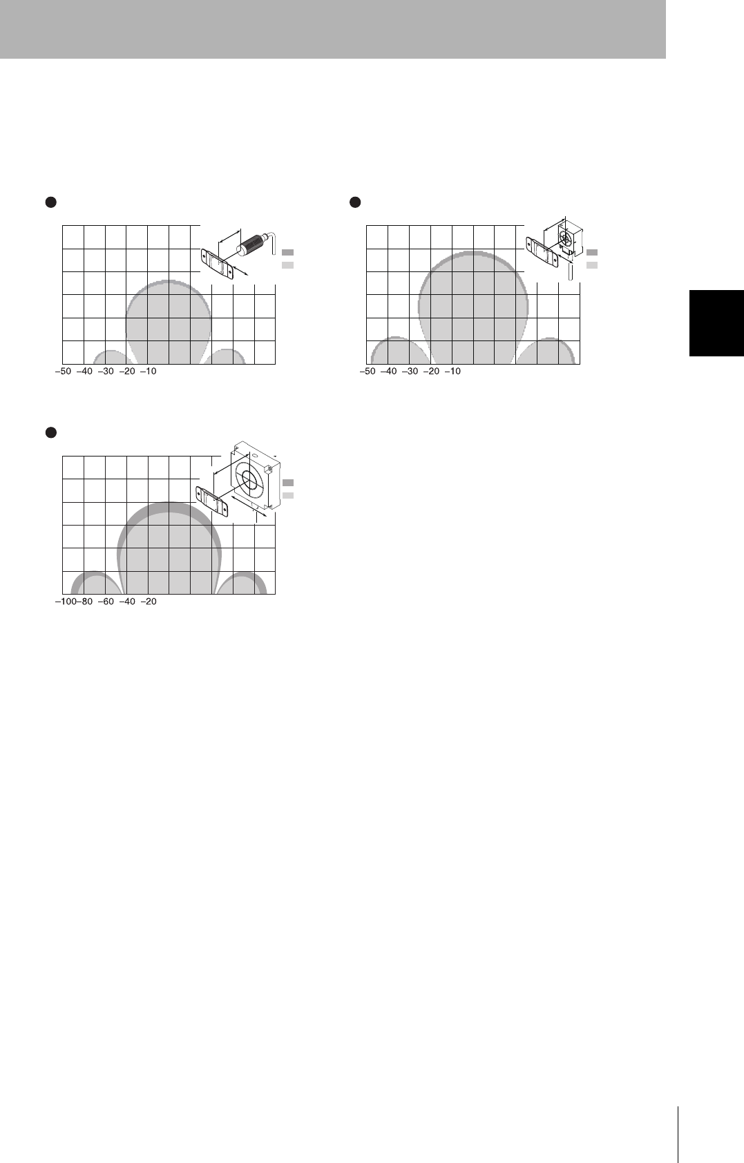
Communications Area (Reference)
The communications areas given here are for reference only. For information on communications distances, refer
to p.44.
The communications area depends on the type of ID Tags used, the ambient temperature, surrounding metals,
and noise. Be sure to check carefully when installing the system.
Read
Write
−15 −10 −50 5−10 15
Y
X
Y
X
V680-HS51 & V680-D1KP52MT
X Axis
Y Axis
0
5
10
15
(Unit: mm)
Read
Write
−15 −10 −50 5−10 15
X Axis
Y Axis
0
5
10
15
(Unit: mm)
V680-HS51 & V680-D1KP52MT
Embedded in Metal (Steel)
V680-HS52 & V680-D1KP52MT
X Axis
Y Axis
V680-HS52 & V680-D1KP52MT
Embedded in Metal (Steel)
−25 −20 −15 −10 −50 510152025
0
5
10
15
20
25
30
(Unit: mm)
Read
Write
Y
X
X Axis
Y Axis
−25 −20 −15 −10 −50 510152025
0
5
10
15
20
25
30
(Unit: mm)
Read
Write
Y
X
V680-HS63 & V680-D1KP52MT
X Axis
Y Axis
−25 −20 −15 −10 −50 510152025
0
5
10
15
20
25
30
(Unit: mm)
Read
Write
Y
X

46
Section 3 Communications Distances
RFID System
User's Manual
Section 3
Communications Specifications
V680-D1KP66T
Communications Distance Specifications (Certified Performance)
• Measurement Conditions
Amplifier Antenna ID Tag Communications distance
V680-HA63A
V680-HS52 V680-D1KP66T Read 0 to 17.0 mm (Axis offset: ±2 mm)
Write 0 to 17.0 mm (Axis offset: ±2 mm)
V680-HS63 V680-D1KP66T Read 0 to 30.0 mm (Axis offset: ±10 mm)
Write 0 to 25.0 mm (Axis offset: ±10 mm)
V680-HS65 V680-D1KP66T Read 0 to 47.0 mm (Axis offset: ±10 mm)
Write 0 to 42.0 mm (Axis offset: ±10 mm)
V680-HS63
V680-D1KP66T
V680-HS52
V680-D1KP66T
Non-metallic material Non-metallic material
(Examples: Resin, plastic, wood, etc.)
Non-metallic material
(Examples: Resin, plastic, wood, etc.)
Non-metallic material
V680-HS65
V680-D1KP66T
Non-metallic material
(Examples: Resin, plastic, wood, etc.)
Metal

47
RFID System
User's Manual
Section 3 Communications Distances
Section 3
Communications Specifications
Communications Area (Reference)
The communications areas given here are for reference only. For information on communications distances, refer
to p.46.
The communications area depends on the type of ID Tags used, the ambient temperature, surrounding metals,
and noise. Be sure to check carefully when installing the system.
V680-HS52 and V680-D1KP66T
(Unit: mm)
Read
Write
V680-HS63 and V680-D1KP66T
(Unit: mm)
Read
Write
−50 −40 −30 −20 −10 0 10 20 30 40 50
0
10
20
30
40
50
60
Y
X
−50 −40 −30 −20 −10 0 10 20 30 40 50
0
10
20
30
40
50
60
Y
X
V680-HS65 and V680-D1KP66T
(Unit: mm)
Read
Write
−100−80−60 −40 −20 0 20 40 60 80 100
0
20
40
60
80
100
120
Y
X
48
Section 3 Communications Distances
RFID System
User's Manual
Section 3
Communications Specifications
V680-D1KP66MT
Communications Distance Specifications (Certified Performance)
• Measurement Conditions
Amplifier Antenna ID Tag Communications Distance
V680-HA63A
V680-HS52 V680-D1KP66MT
with metal on back surface (steel)
Read 0 to 16.0 mm (Axis offset: ±2 mm)
Write 0 to 14.0 mm (Axis offset: ±2 mm)
V680-HS63 V680-D1KP66MT
with metal on back surface (steel)
Read 0 to 25.0 mm (Axis offset: ±10 mm)
Write 0 to 20.0 mm (Axis offset: ±10 mm)
V680-HS65 V680-D1KP66MT
with metal on back surface (steel)
Read 0 to 25.0 mm (Axis offset: ±10 mm)
Write 0 to 20.0 mm (Axis offset: ±10 mm)
V680-HS63
V680-D1KP66MT
V680-HS52
Metal
V680-D1KP66MT
Metal
Non-metallic material
Non-metallic material
V680-HS65
V680-D1KP66MT
Metal
Metal
49
RFID System
User's Manual
Section 3 Communications Distances
Section 3
Communications Specifications
Communications Area (Reference)
The communications areas given here are for reference only. For information on communications distances, refer
to p.48.
The communications area depends on the type of ID Tags used, the ambient temperature, surrounding metals,
and noise. Be sure to check carefully when installing the system.
(Unit: mm)
Read
Write
(Unit: mm)
Read
Write
V680-HS52 and V680-D1KP66MT
with Metal on Back Surface (Steel)
V680-HS63 and V680-D1KP66MT
with Metal on Back Surface (Steel)
−50 −40 −30 −20 −10 0 10 20 30 40 50
0
10
20
30
40
50
60
Y
X
−50 −40 −30 −20 −10 0 10 20 30 40 50
0
10
20
30
40
50
60
Y
X
(Unit: mm)
Read
Write
V680-HS65 and V680-D1KP66MT
with Metal on Back Surface (Steel)
−100 −80−60 −40 −20 0 20 40 60 80 100
0
20
40
60
80
100
120
Y
X
50
Section 3 Communications Distances
RFID System
User's Manual
Section 3
Communications Specifications
V680-D1KP66T-SP
Communications Distance Specifications (Certified Performance)
• Measurement Conditions
Amplifier Antenna ID Tag Communications distance
V680-HA63A
V680-HS52 V680-D1KP66T-SP Read 0 to 15.0 mm (Axis offset: ±2 mm)
Write 0 to 15.0 mm (Axis offset: ±2 mm)
V680-HS63 V680-D1KP66T-SP Read 0 to 25.0 mm (Axis offset: ±10 mm)
Write 0 to 20.0 mm (Axis offset: ±10 mm)
V680-HS65 V680-D1KP66T-SP Read 0 to 42.0 mm (Axis offset: ±10 mm)
Write 0 to 37.0 mm (Axis offset: ±10 mm)
V680-HS63
V680-D1KP66T-SP
Non-metallic material
V680-HS52
Non-metallic material
V680-D1KP66T-SP
Non-metallic material
(Examples: Resin, plastic, wood, etc.)
Metal
V680-HS65
V680-D1KP66T-SP
Non-metallic material
(Examples: Resin, plastic, wood, etc.)
Non-metallic material
(Examples: Resin, plastic, wood, etc.)
51
RFID System
User's Manual
Section 3 Communications Distances
Section 3
Communications Specifications
Communications Area (Reference)
The communications areas given here are for reference only. For information on communications distances, refer
to p.50.
The communications area depends on the type of ID Tags used, the ambient temperature, surrounding metals,
and noise. Be sure to check carefully when installing the system.
Y
X
Y
X
Y
X
V680-HS52 and V680-D1KP66T-SP
(Unit: mm)
Read
Write
V680-HS63 and V680-D1KP66T-SP
(Unit: mm)
Read
Write
01020304050
0
10
20
30
40
50
60
01020304050
0
10
20
30
40
50
60
V680-HS65 and V680-D1KP66T-SP
(Unit: mm)
Read
Write
020406080 100
0
20
40
60
80
100
120
52
Section 3 Communications Distances
RFID System
User's Manual
Section 3
Communications Specifications
V680-D1KP58HT
Communications Distance Specifications (Certified Performance)
• Measurement Conditions
Communications Area (Reference)
The communications areas given here are for reference only. For information on communications distances, refer
to p.52.
The communications area depends on the type of ID Tags used, the ambient temperature, surrounding metals,
and noise. Be sure to check carefully when installing the system.
Antenna ID Tag Communications distance
V680-H01-V2 V680-D1KP58HT Read 0 to 150.0 mm (Axis offset: ±10mm)
Write 0 to 150.0 mm (Axis offset: ±10mm)
V680-H01-V2
V680-D1KP58HT
Non-metallic materialNon-metallic material
V680-H01-V2 and V680-D1KP58HT
(Unit: cm)
Read
Write
0 5 10 15 20 25
0
10
15
20
25
30
-25 -20 -15 -10 -5
5
㪰
㪯
X Axis
Y Axis
53
RFID System
User's Manual
Section 3 Communication Time (Reference)
Section 3
Communications Specifications
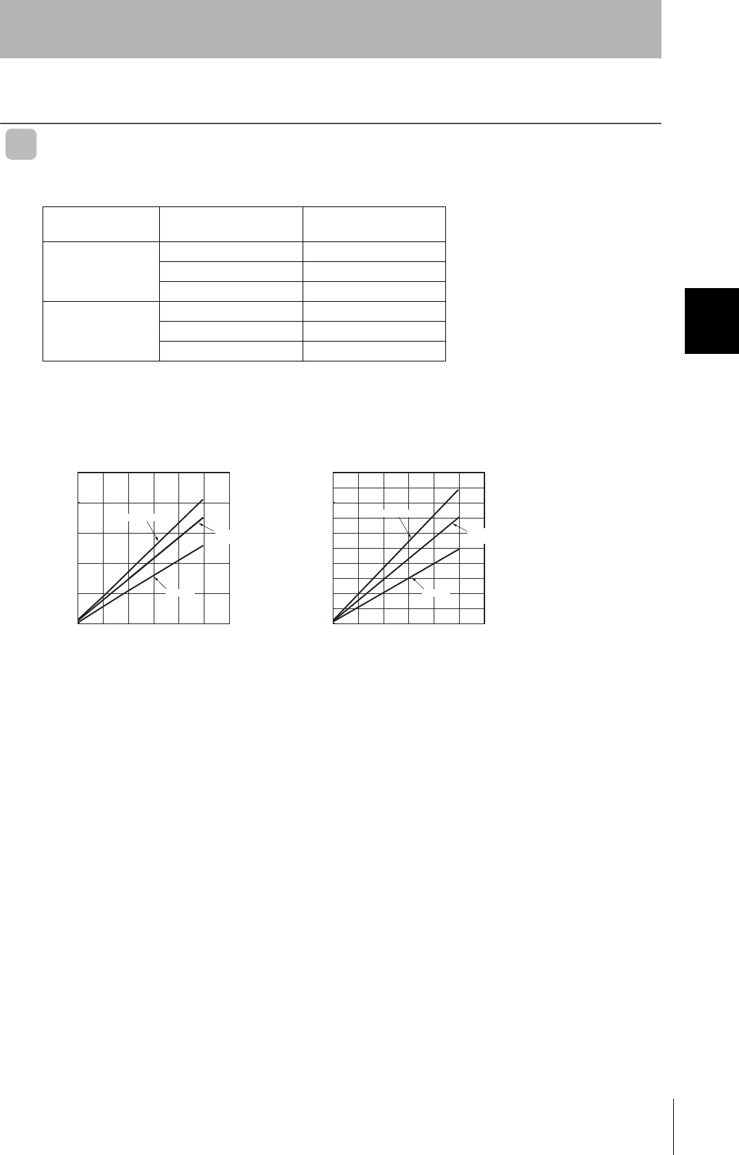
Communication Time (Reference)
Communications Time (Reference)
Communications Time
V680-HA63A:V680-HS@@:V680-H01-V2:V680-D1KP@@
Note: When using multi-access or FIFO communications options, normal-mode communications speed will be
used regardless of the high-speed mode setting.
Note: The high-speed mode cannot be used when SW1-1 on the V680-H01-V2 Antenna is turned ON.
Communications
speed setting
Command Communications time
N: No. of bytes processed
Normal mode Read T = 1.3 N + 31
Write (with verification) T = 2.1 N + 58
Write (without verification) T = 1.8 N + 56
High-speed mode
(See note.)
Read T = 1.0 N + 29
Write (with verification) T = 1.8 N + 51
Write (without verification) T = 1.5 N + 47
Communications speed: Normal mode Communications speed: high-speed mode
2,500
2,000
1,500
1,000
500
0200 400 600 800 1,000 1,200
No. of bytes (byte)
Write (with verification)
Reading
Write
(without verification)
2,000
1,600
1,200
800
400
0200 400 600 800 1,000 1,200
No. of bytes (byte)
1,800
1,400
1,000
600
200
Write (with verification)
Reading
Communications time (ms)
Communications time (ms)
Write
(without verification
)
54
Section 3 Communication Time (Reference)
RFID System
User's Manual
Section 3
Communications Specifications
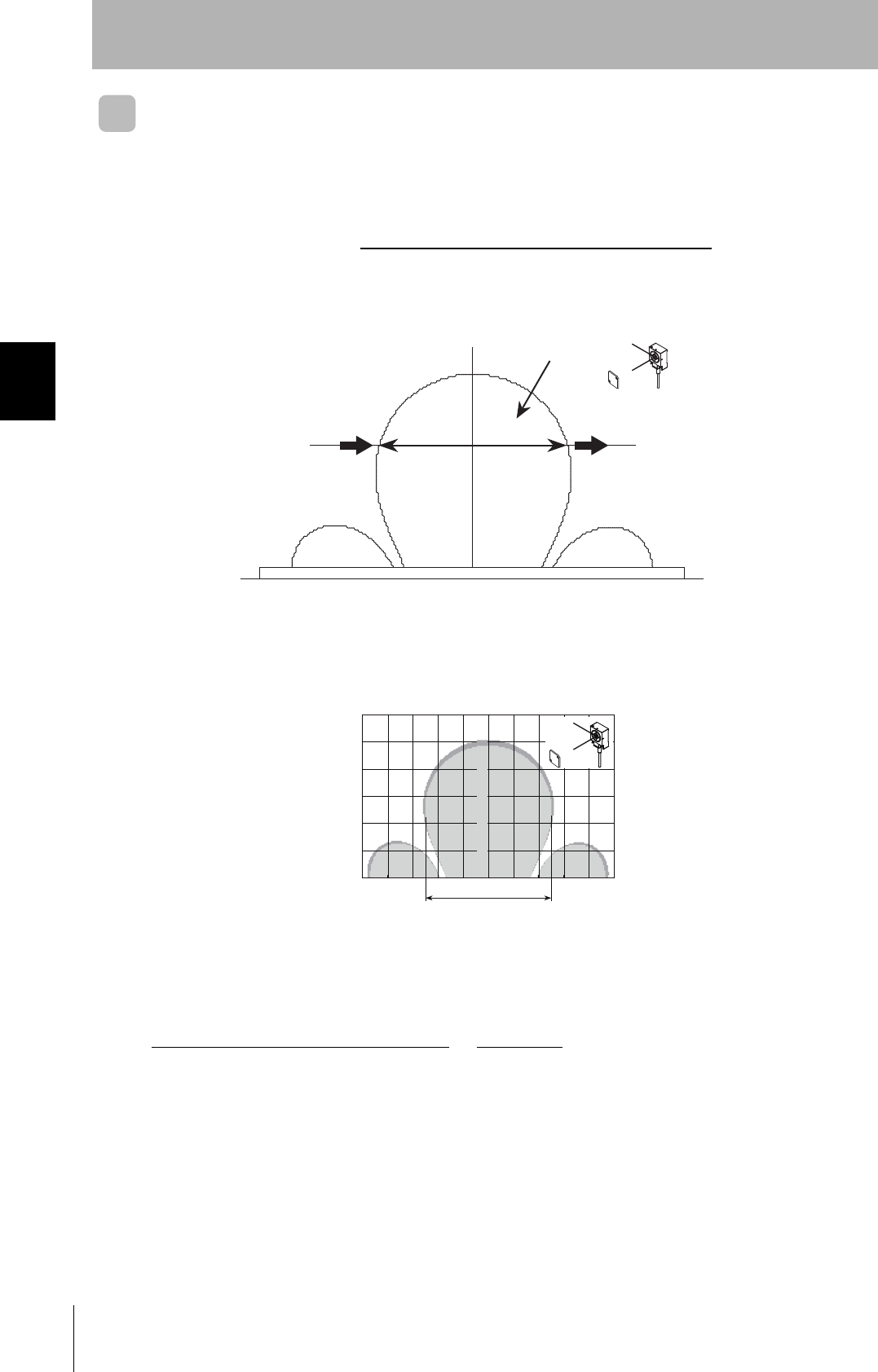
Calculating Tag Speed
When communicating with a moving Tag, specify an AUTO command or POLLING command.
The maximum speed for communicating with the Tag can be calculated simply using the following for-
mula.
D (Distance travelled in communications area) is calculated from the actual measurement or the com-
munications area between the Antenna and Tag.
Calculation Example
In this example diagram, the V680-D1KP66T, V680-HA63A, and V680-HS63 are combined and 256
bytes are read.
This diagram shows the following:
Distance travelled in communications area (D) = 50 mm when Y (communications distance) = 20 mm
Communications time, T = 1.3N +31 = 1.3 × 256 + 31 = 363.8 (ms)
Accordingly, the movement speed in this case will be as follows:
Note 1. The distance travelled in the communications area depends on the read/write distance and the
axis offset. Refer to the diagrams in Communications Area.
2. The speed of the Tag is provided as a guideline. Before using the RFID System, run a test to
determine the speed under actual operating conditions.
3. The above values do not take into account the processing of errors in communications with the
host device or Tags.
Maximum speed = D (Distance travelled in communications area)
T (Communications time)
X
Y
Y
X
Unit: mm
D
Direction of travel
Communications area
Y
−50 −40 −30 −20 −10 0 10 20 30 40 X
(Unit: mm)
50 mm
X
Y
40
30
20
10
50
=
Distance travelled in communications area
Communications time
50 (mm)
363.8 (ms)
= 8.24 m/min

Section 4 Installation
55
RFID System
User's Manual
Section 4
Installation
Installing Antennas 56
Mounting Amplifiers 65
Installing Tags 67
56
Section 4 Installing Antennas
RFID System
User's Manual
Section 4
Installation
Installing Antennas
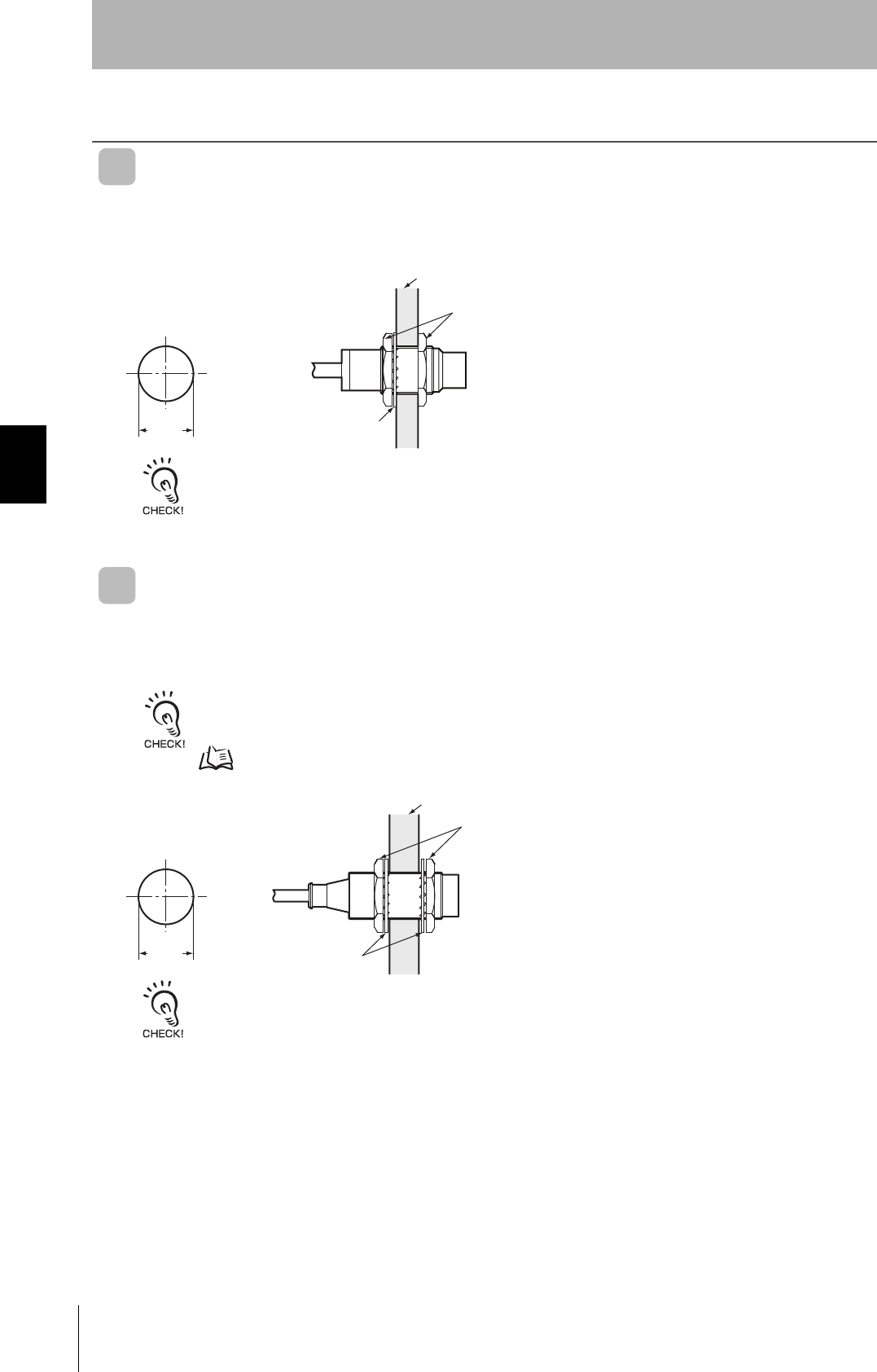
V680-HS51
Install the Antenna using the nuts and toothed washers that are provided on both sides of the mounting
material, as shown in the diagram below.
Securely tighten the screws to a maximum torque of 6 N⋅m.
V680-HS52
Install the Antenna using the nuts and toothed washers that are provided on both sides of the mounting
material, as shown in the diagram below.
When the Antenna is mounted to a metal object, the communications distance will be reduced by approximately 10%
compared with mounting to a non-metallic object. For details on the effect of metal surrounding the Antenna, refer to
Effect of Surrounding Metals on the Antenna (Reference) on page 61.
P.61
Securely tighten the screws to a maximum torque of 40 N⋅m.
12
+0.5
0
Mounting Hole Dimensions
dia.
Material
Antenna
Nuts
Toothed washer
22
+0.5
0
Mounting Hole Dimensions
dia.
Toothed washers
Non-metallic material
Antenna
Nuts
57
RFID System
User's Manual
Section 4 Installing Antennas
Section 4
Installation
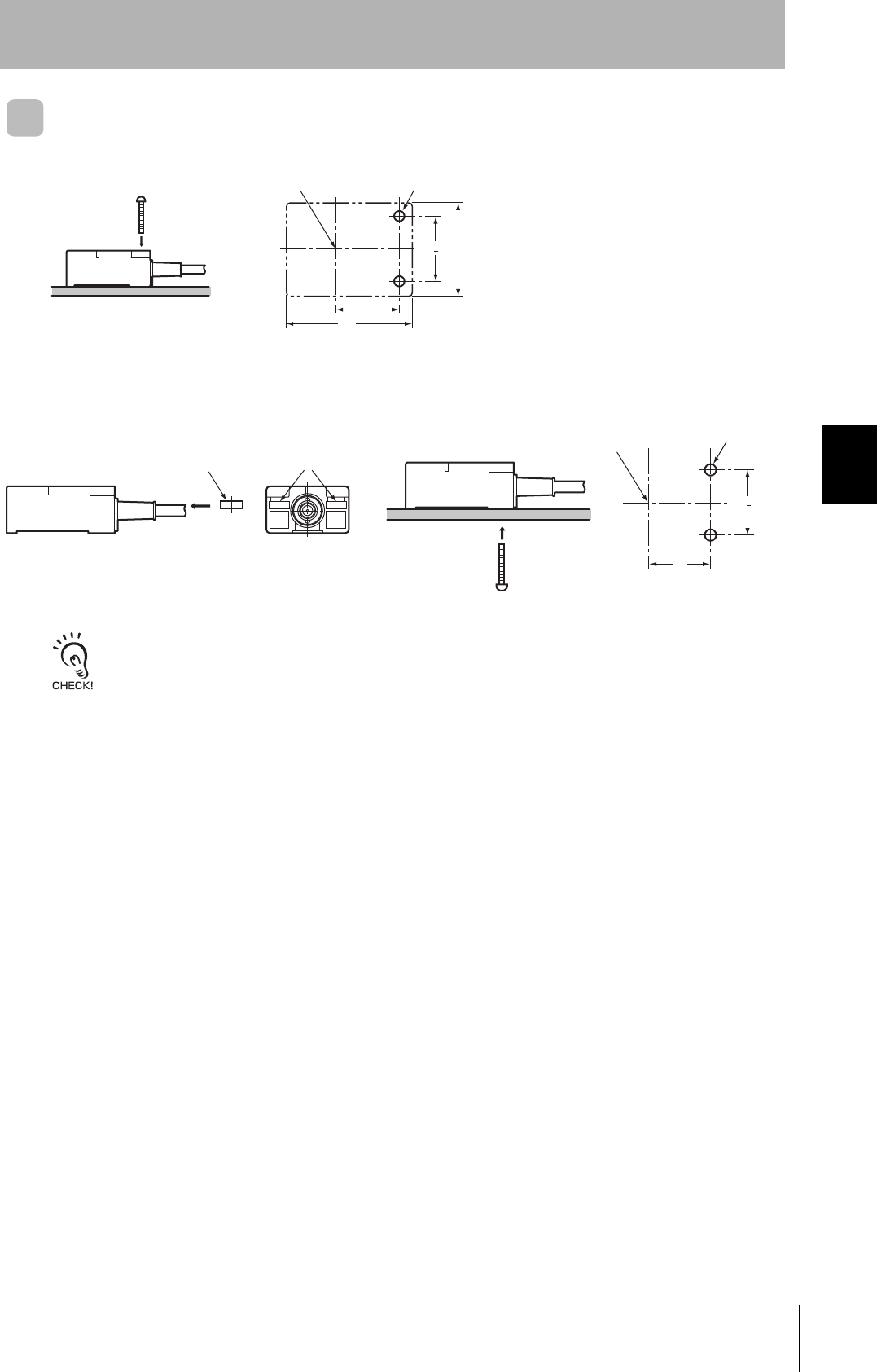
V680-HS63
Installation from the Front
Installation from the Back
Insert the nuts that come with the Antenna into sections A.
Securely tighten screws to a maximum torque of 1.2 N⋅m.
28+0.2 40
27
53
Coil center Two, M4 holes
28+0.2
A
27
Nut
Two, 4.5 dia. holesCoil center
58
Section 4 Installing Antennas
RFID System
User's Manual
Section 4
Installation
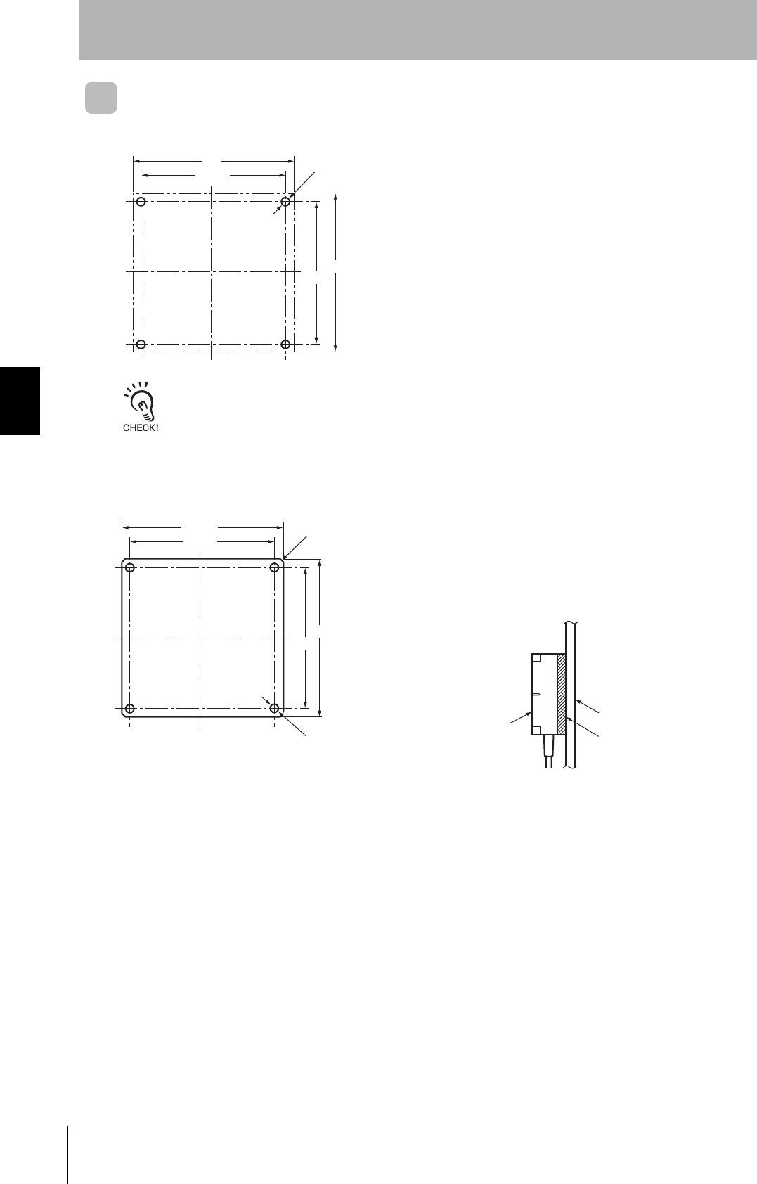
V680-HS65
Securely tighten screws to a torque of 0.7 to 1.2 N⋅m.
Mounting Bracket Dimensions (Provided Only with the V680-HS65)
Use M4 screws and spring washers (in four places) for
Antenna installation.
Tighten the screws to a torque of 0.7 to 1.2 N⋅m.
There are no restrictions on the mounting direction or
the direction of access to the Tag, but if the Antenna is to
be installed near a device such as a conveyance belt,
make sure there is no danger of the Antenna being
accidentally struck.
Four, M4
mounting holes
100
100
90±0.2
90±0.2
Four, 1-mm
corners
V680-HS65
100±0.2
90±0.1
Four, 4.5-dia. holes
Mounting base
Mounting Bracket (provided)
90±0.1
100±0.2
Note: When installing the Antenna, mount it on the
enclosed Mounting Bracket. The Mounting
Bracket is not necessary, however, if the Antenna
is mounted on a metal base that is larger than the
Antenna (100 × 100 mm).
59
RFID System
User's Manual
Section 4 Installing Antennas
Section 4
Installation
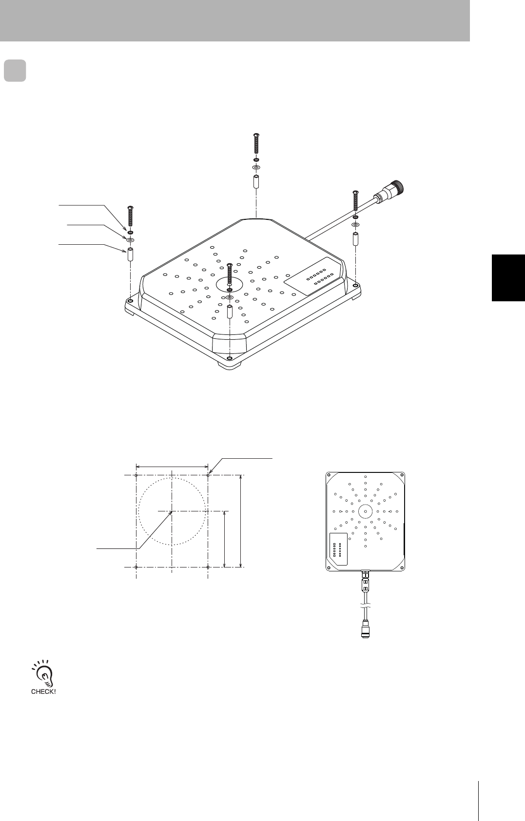
V680-H01-V2
Be sure to insert the provided fittings into the Antenna mounting holes and mount the Antenna with
four M4 screws with spring washers and flat washers as shown below.
Securely tighten screws to a maximum torque of 1.2 N⋅m.
142.5
235±0.2
185±0.2
M4 or 4.5 dia.
Coil center
Mounting Hole Dimensions
䋨Unit䋺mm䋩
Spring washer
Flat washer
Provided fitting
60
Section 4 Installing Antennas
RFID System
User's Manual
Section 4
Installation
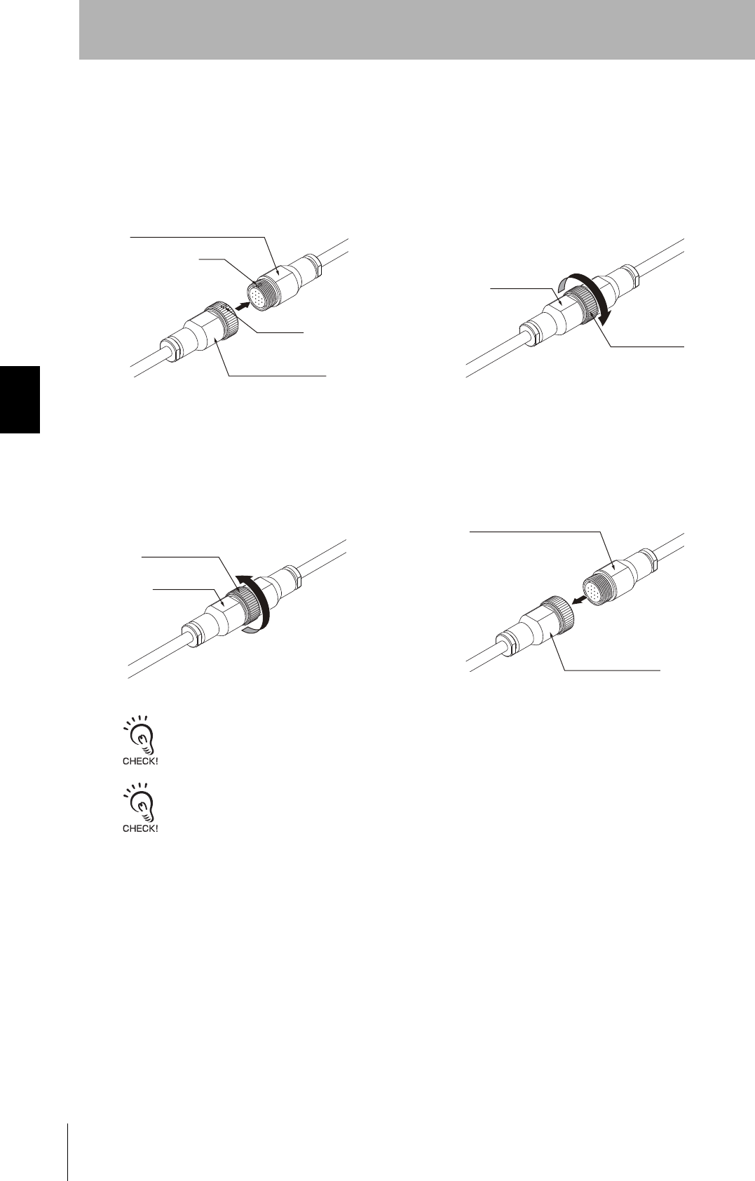
Connecting and Disconnecting Extension Cables
Mounting the Antenna
Removing the Antenna
When loosening the connection ring, always hold the flat surfaces on the Antenna connector with a wrench. If the con-
nection ring is loosened without holding the Antenna connector, the extension cable may be damaged or wire inside the
extension cable may break.
The connector cannot be pulled out without first loosening the connection ring. Completely loosen the connection ring
before pulling out the connector. Pulling on the cable without sufficiently loosening the connection ring may cause the
cable to be damaged or wire inside the cable may break.
1. Align the key on the extension cable con-
nector with the key slot on the Antenna
connector and push the connector all the
way in.
2. Hold the flat surfaces on the Antenna connector
with a wrench, and turn the connection ring clock-
wise to secure the connector
3. Hold the flat surfaces on the Antenna con-
nector with a wrench, and turn the connec-
tion ring counterclockwise to loosen the
connector.
4. Make sure that the connection ring is sufficiently
loose, and then pull the connector straight out.
Antenna connector
Extension cable connector
Key
Key ditch
Connection rin
Flat surface
Connection ring
Flat surface
Antenna connector
Extension cable connector
61
RFID System
User's Manual
Section 4 Installing Antennas
Section 4
Installation
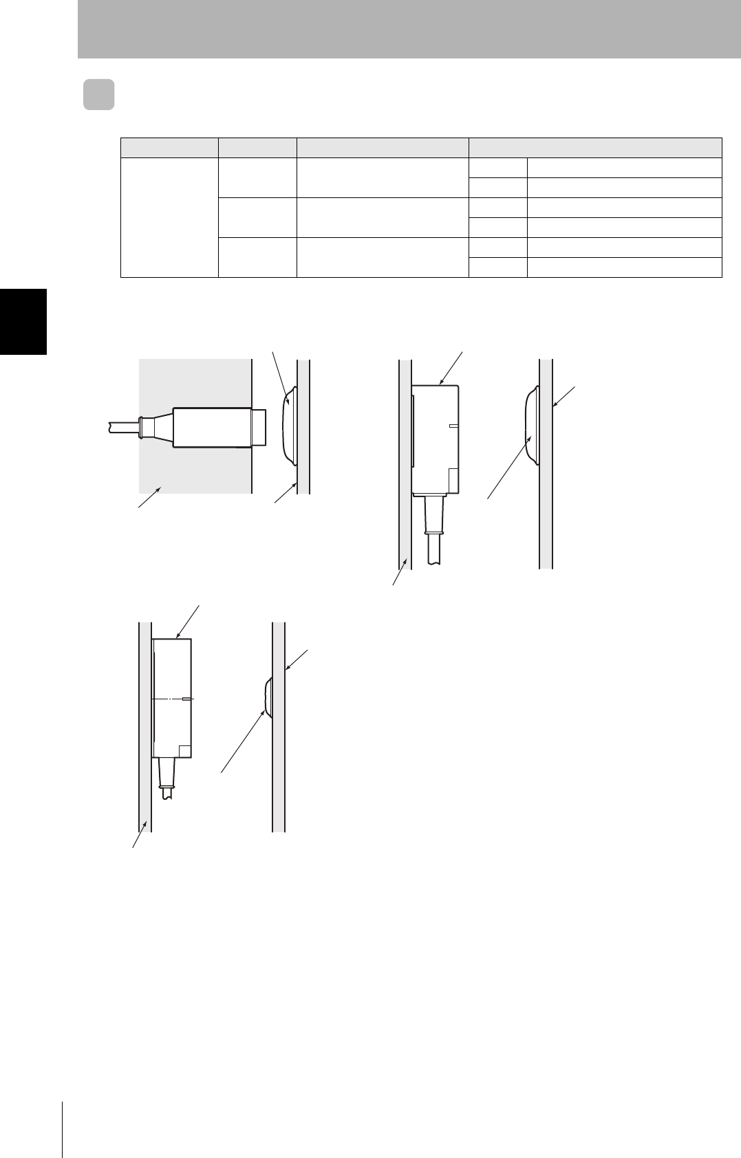
Effect of Surrounding Metals on the Antenna (Reference)
V680-HS51
When embedding the Antenna in metal, be sure the metal does not extend beyond the tip of the
Antenna.
V680-HS52
When embedding the Antenna in metal, be sure the metal does not extend beyond the tip of the
Antenna.
120 (±60) mm dia. min.
7 mm min.
Antenna
12 mm dia.
Surrounding metal
(steel)
Communications
distance
reduced by 50%.
Antenna
Surrounding metal
(steel)
40mm min.
R18 min.
Do not bend the cable into a curve tighter
than 18 mm in radius.
If the metal around the Antenna reaches the coil surface, the
communications distance will be reduced significantly com-
pared with mounting to a non-metallic surface.
130 (±65) mm dia. min. 22 mm dia.
R22 min.
15 mm min.
Surrounding metal
(steel)
Communications
distance
reduced by 50%.
Antenna
60mm min.
Surrounding metal
(steel)
Antenna
Do not bend the cable into a curve tighter
than 22 mm in radius.
If the metal around the Antenna reaches the coil surface, the
communications distance will be reduced significantly com-
pared with mounting to a non-metallic surface.
62
Section 4 Installing Antennas
RFID System
User's Manual
Section 4
Installation
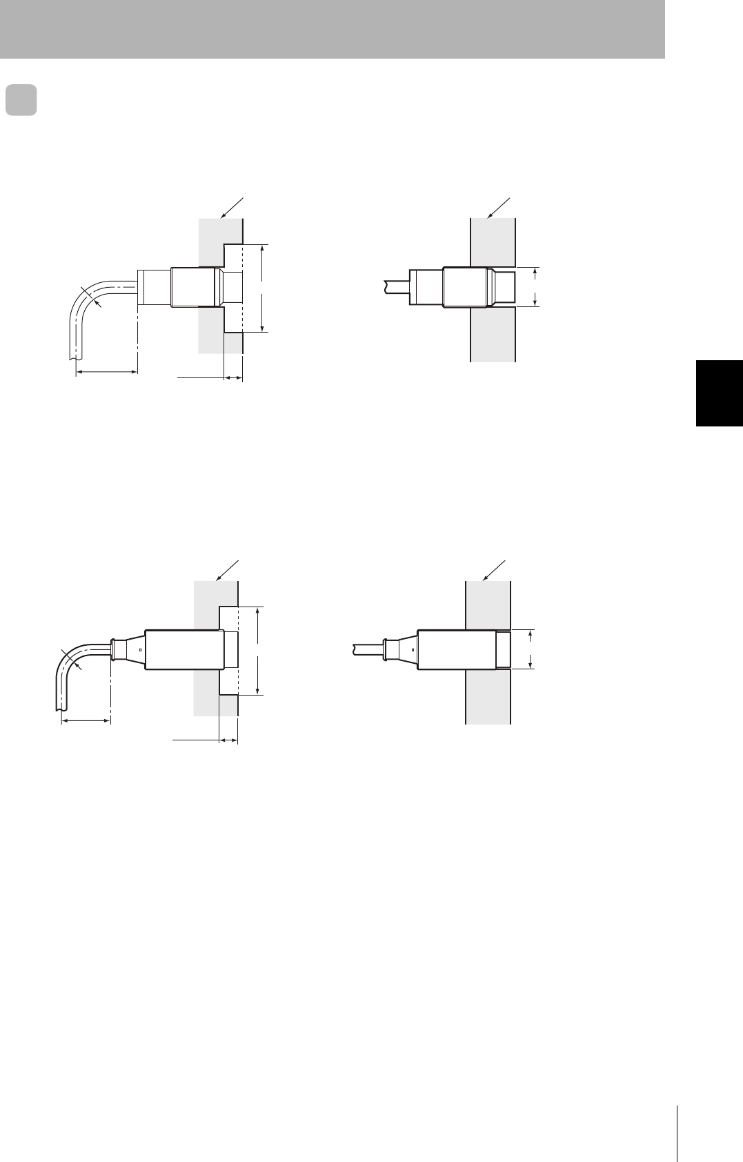
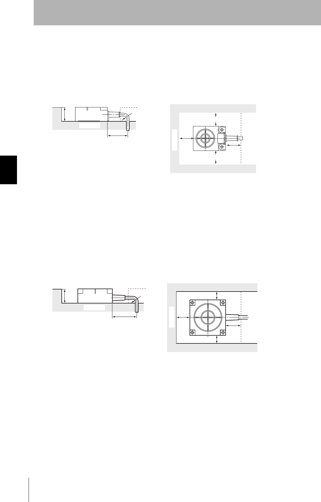
V680-HS63
In addition to surface mounting, it is also possible to embed the V680-HS63 in a metal casing to protect
it from being struck by other objects. To prevent malfunctioning, allow a space of at least 30 mm
between the Antenna and the sides of the metal casing. If the space is less than 30 mm, the read/write
distance will be greatly diminished. In addition, the height of metal casing must not exceed that of the
Antenna.
V680-HS65
In addition to surface mounting, it is also possible to embed the V680-HS65 in a metal casing to protect
it from being struck by other objects. To prevent malfunctioning, allow a space of at least 100 mm
between the Antenna and the sides of the metal casing. If the space is less than 100 mm, the read/
write distance will be greatly diminished. In addition, the height of metal casing must not exceed that of
the Antenna.
V680-H01-V2
If the Antenna is mounted to a metal object, the communications area will be reduced by approximately
10%compared with mounting to a non-metal object. Consider this influence on performance when
mounting the Antenna.
R22 min.
60 mm min.
23 mm
max.
Metal casing
Metal casing
30 mm
min.
30 mm min.
30 mm min.
30 mm
min.
Note 1. Do not bend the cable into a curve
tighter than 22 mm in radius.
2. The communications distance will
be reduced significantly if the
Antenna is installed closer than 30
mm to metal surfaces.
R22 min.
60 mm min.
30 mm
max.
Metal casing
Metal casing
100 mm
min.
100 mm min.
100 mm min.
100 mm
min.
Note 1. Do not bend the cable into a curve
tighter than 22 mm in radius.
2. The communications distance will
be reduced significantly if the
Antenna is installed closer than 100
mm to metal surfaces.
63
RFID System
User's Manual
Section 4 Installing Antennas
Section 4
Installation
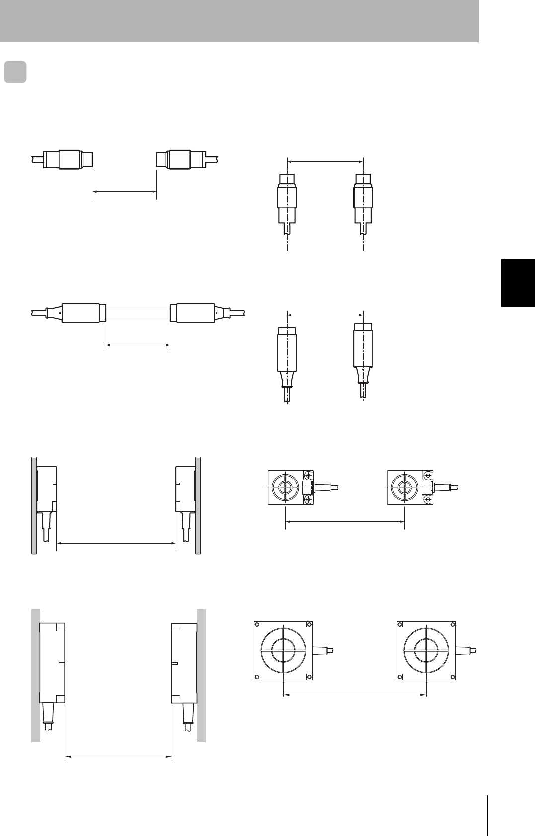
Mutual Interference between Antennas (Reference)
To prevent malfunctioning due to mutual interference when using more than one Antenna, leave suffi-
cient space between them as shown in the following diagrams.
V680-HS51
V680-HS52
V680-HS63
V680-HS65
80 mm min.
80 mm min.
• Installing the Antennas Facing Each Other • Installing the Antennas in Parallel
120 mm min.
100 mm min.
• Installing the Antennas Facing Each Other • Installing the Antennas in Parallel
420 mm min.
260 mm min.
• Installing the Antennas Facing Each Other • Installing the Antennas in Parallel
• Installing the Antennas Facing Each Other • Installing the Antennas in Parallel
700 mm min.
400 mm min.
64
Section 4 Installing Antennas
RFID System
User's Manual
Section 4
Installation
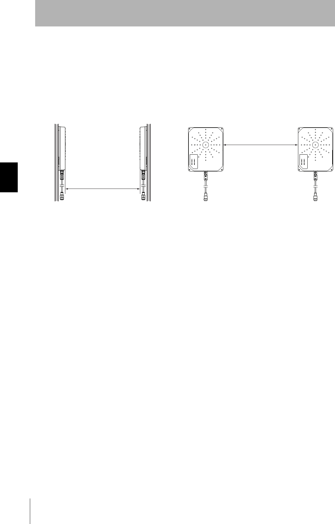
V680-H01-V2
When installing multiple Read/Write Antennas adjacently, make sure that the Antenna communications
area do not overlap.
For details on the Antenna communications area, refer to Communications Area (Reference).
As a guide, the following diagrams show the minimum distances required between two Antennas
installed facing each other or in parallel. Be sure to provide the distance between Antennas shown
here.
1m min.
50cm min
• Installing the Antennas Facing Each Other • Installing the Antennas in Parallel
65
RFID System
User's Manual
Section 4 Mounting Amplifiers
Section 4
Installation
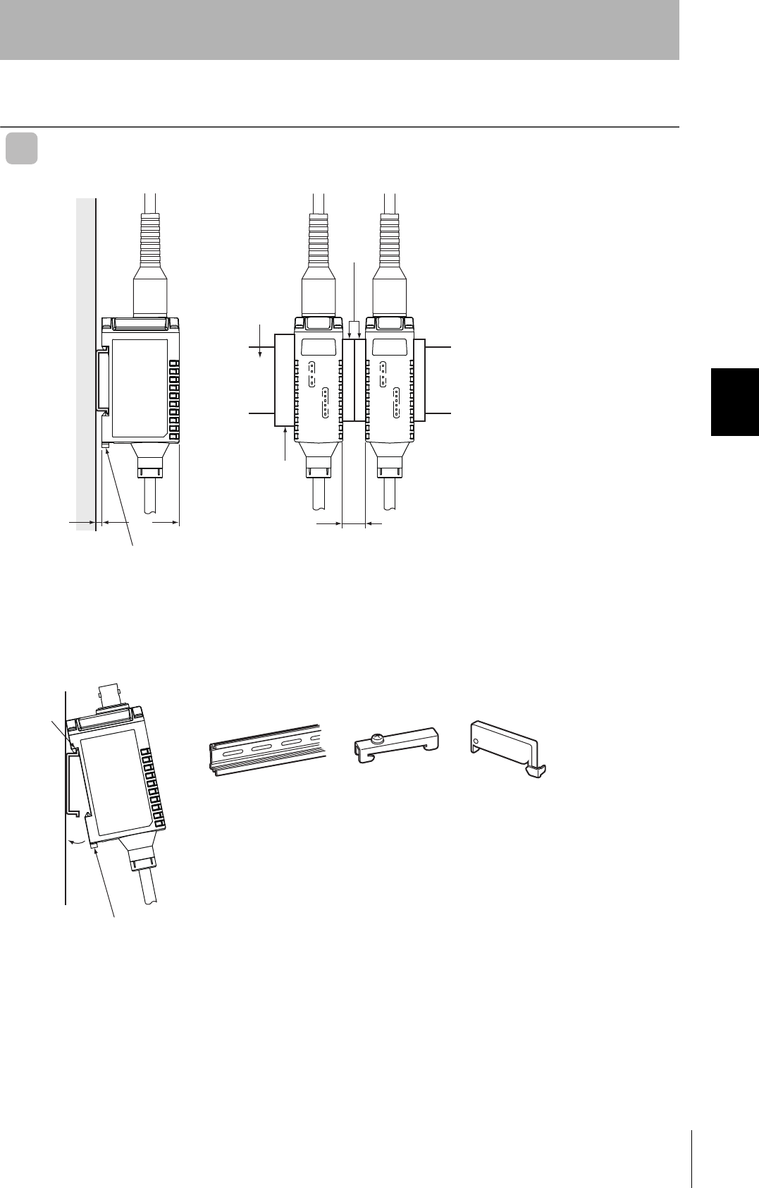
Mounting Amplifiers
V680-HA63A
Mounting to DIN Track
Note 1. Consider the height of the DIN Track.
2. Provide a space of at least 10 mm (i.e., at least two spacers) and attach them
securely.
40
End Plate
10 mm min.
(See note 2.)
Mounting hook
(See note 1.)
DIN Track
Spacers
A
B
PFP-100N2 PFP-M PFP-S
Mounting hook
End Plate Spacer
DIN Track
1. When mounting the Amplifier to a DIN Track, first
hook section A to the Track and then press in
direction B.
2. To remove the Amplifier from the DIN Track, first pull
out the mounting hook.
66
Section 4 Mounting Amplifiers
RFID System
User's Manual
Section 4
Installation
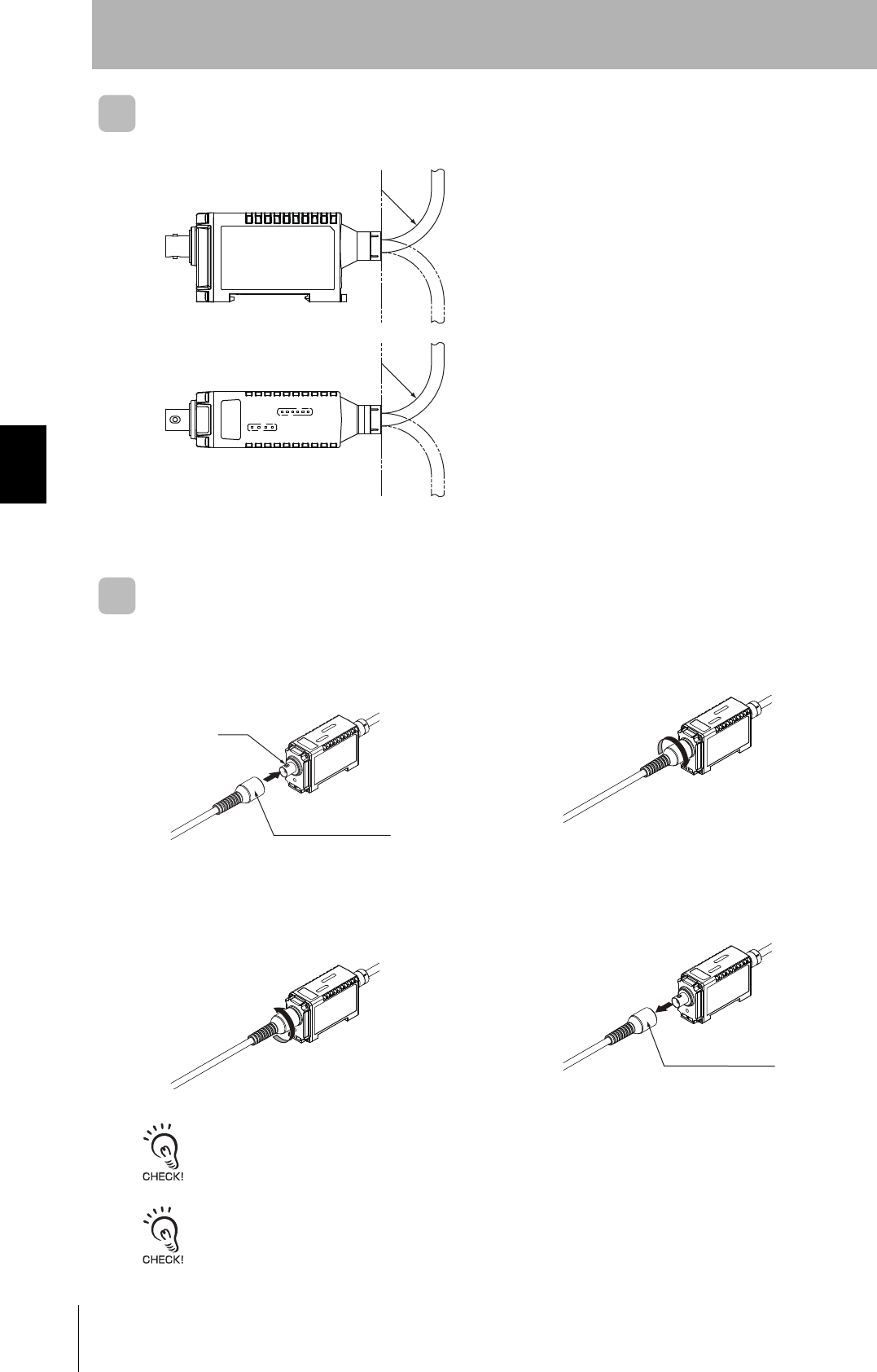
Amplifier Cable Bending Radius
Attaching/Removing Amplifire and Antenna Connectors
Attaching the Connector
Removing the Connector
The connector will not come out unless the lock is first released by turning the connector. To remove the cable, release
the lock and pull on the connector. Pulling the cable without releasing the lock may break or damage the cable.
Do not pull the Antenna connector over the power of 30 N.
The Antenna connector may be broken.
1. Hold the Antenna connector, align the key,
and insert the connector into the Amplifier
connector.
2. Turn the connector clockwise to lock it in place.
1. Turn the connector counterclockwise to
release the lock.
2. Pull the Antenna connector straight out.
R35 or
greater
R35 or
greater
Do not bend the cable past a bending radius of 35 mm.
Key
Antenna connector
Antenna connector
67
RFID System
User's Manual
Section 4 Installing Tags
Section 4
Installation
Installing Tags
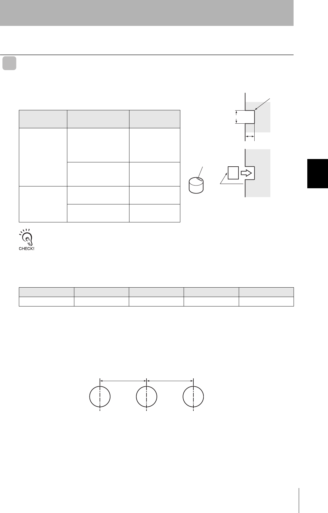
V680-D1KP52MT
Tag Installation Direction
Mount Tags as shown in the diagram on the right.
The epoxy adhesives listed in the following table are recom-
mended for the given temperature ranges.
When embedding the V680-D1KP52MT into a metal surface, use the V680-HS52 Antenna.
Transmission will not be possible if the V680-HS63 Antenna is used.
Differences in Surrounding Metals
Communications distances are affected by the type of metal in back of or surrounding the Tag, as
shown in the following table.
The values for steel are set to 100%
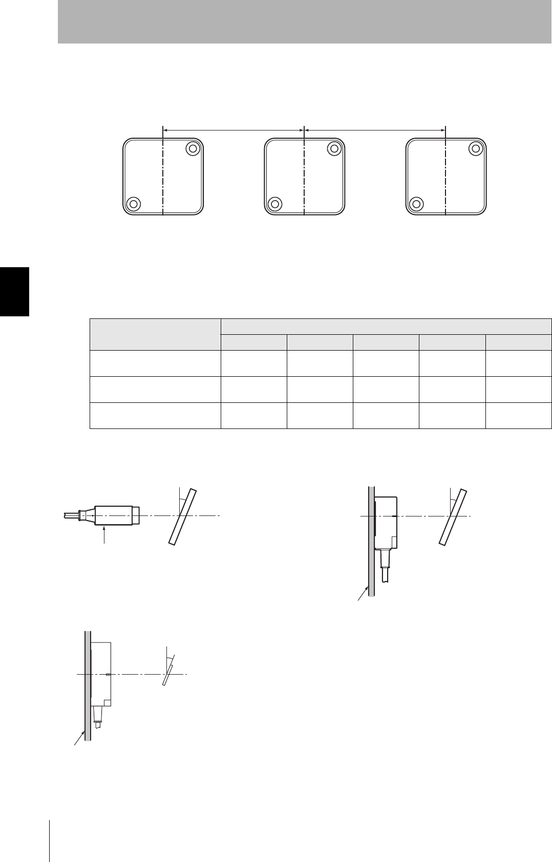
Mutual Interference with Tags (Reference)
Provide the mounting distances indicated below to prevent malfunctions due to mutual interference
when using more than one Tag.
Ambient operat-
ing temperature Product name Manufacturer
−40 to 70°C
Two-part Epoxy-com-
pound Resin:
TB2001 (main agent)/
TB2105C (curing agent)
Three Bond Co.,
Ltd.
One-part Moisture-cur-
ing Elastic Adhesive
TB1530
Three Bond Co.,
Ltd.
−40 to 150°C
One-part Epoxy Resin:
TB2285
Three Bond Co.,
Ltd.
Two-part Epoxy Resin:
TB2087
Three Bond Co.,
Ltd.
Steel SUS Brass Aluminum
V680-D1KP52MT 100% 85% to 90% 80% to 85% 80% to 85%
R0.2 max.
8.1 +0.1
0
5+0.1
0
V680-D1KP52MT
Marked side
Marked side
V680-
D1KP52MT
JAPAN
dia.
25 mm min. 25 mm min.
68
Section 4 Installing Tags
RFID System
User's Manual
Section 4
Installation
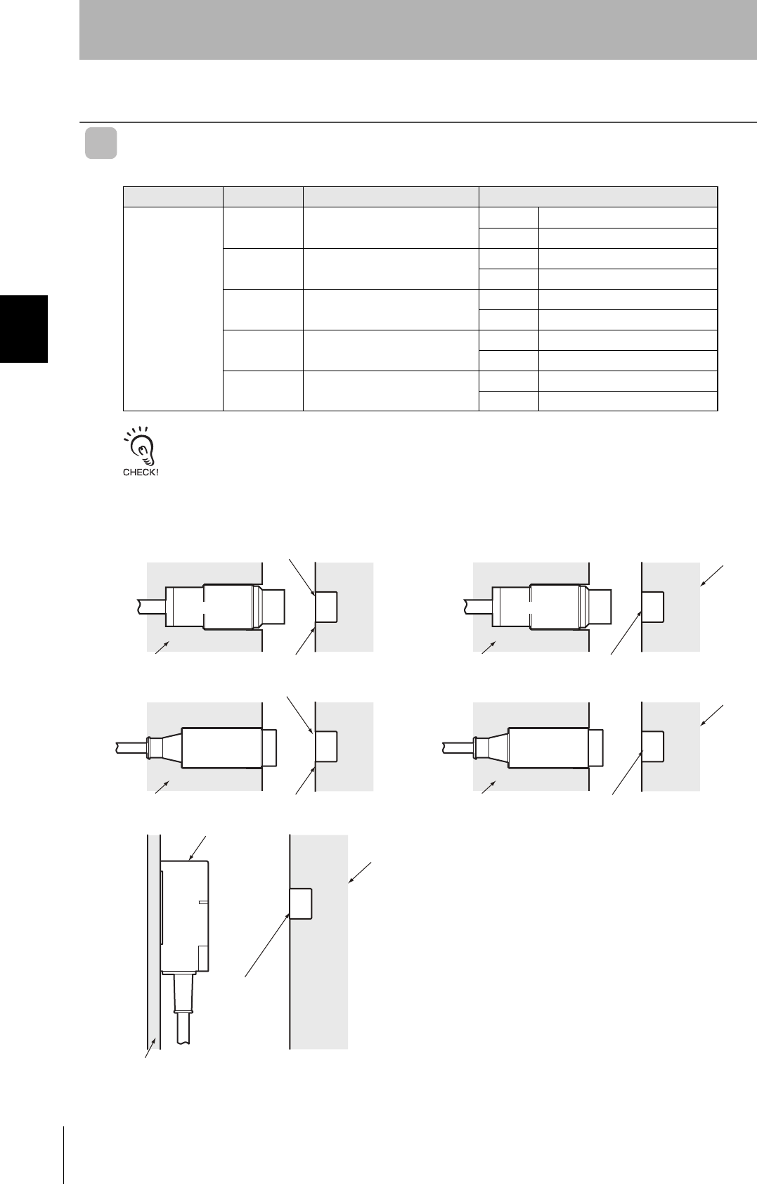
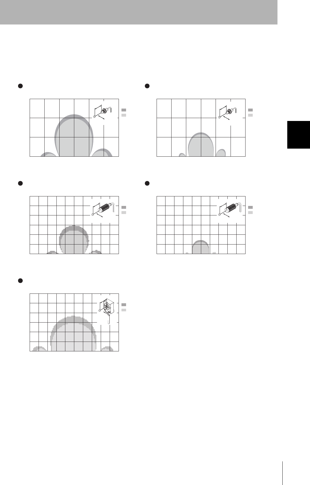
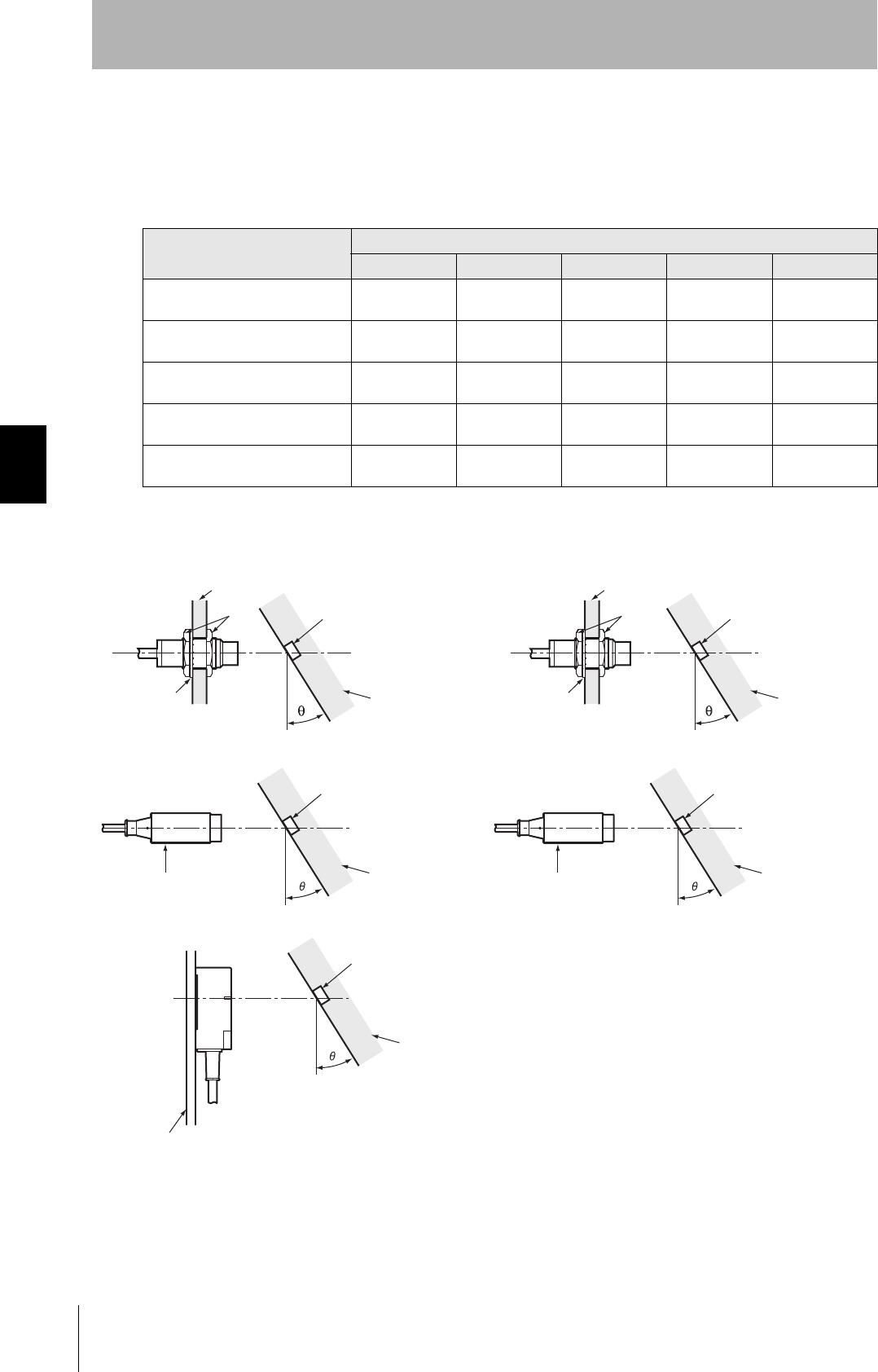
Influence of Angle (Reference)
Install Antennas and Tags as close to parallel to each other as possible. Communications are possible
even when an Antenna and a Tag are mounted at an angle, but the communications distance will be
shortened. The relation between the angle and the communications distance is shown below.
Percentage Drop in Communications Distance According to Angle of V680-D1KP52MT
Tag angle (θ°)
010 20 30 40
V680-HS51 and V680-D1KP52MT 0% -1% -5% -10% -15%
V680-HS51 and V680-D1KP52MT
(Metal: Steel) 0% 0% 0% -4% -28%
V680-HS52 and V680-D1KP52MT 0% 0% 0% -2% -6%
V680-HS52 and V680-D1KP52MT
(Metal: Steel) 0% -6% -13% -25% -
V680-HS63 and V680-D1KP52MT 0% -2% -5% -9% -14%
-: The measurement is no possible because the Tag comes in contact with the Antenna.
• V680-HS51 and V680-D1KP52MT • V680-HS51 and V680-D1KP52MT (Metal: Steel)
• V680-HS52 and V680-D1KP52MT • V680-HS52 and V680-D1KP52MT (Metal: Steel)
• V680-HS63 and V680-D1KP52MT
Tag
Non-metallic material
Antenna
Steel
Nuts
Toothed washer
Tag
Steel
Antenna
Steel
Nuts
Toothed washer
Antenna
Ta g
Non-metallic material
Antenna
Ta g
Steel
Ta g
Non-metallic
material
Antenna
Non-Metallic material
69
RFID System
User's Manual
Section 4 Installing Tags
Section 4
Installation
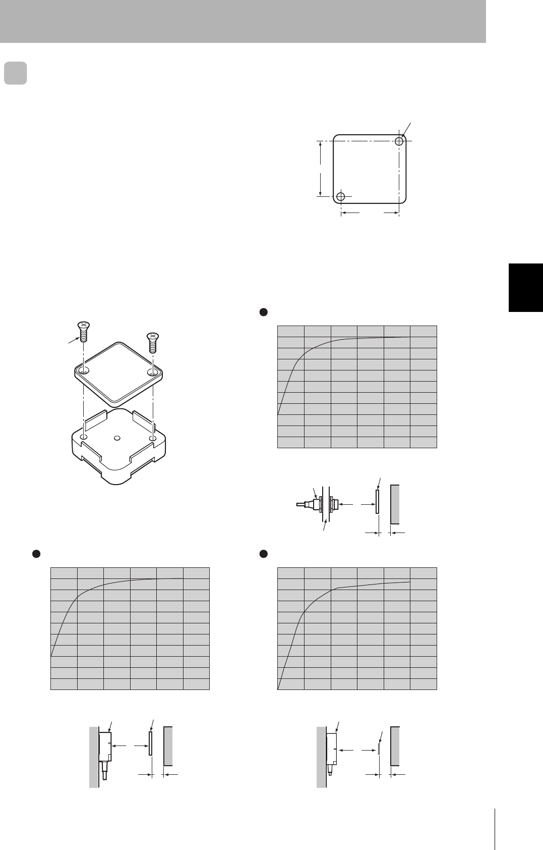
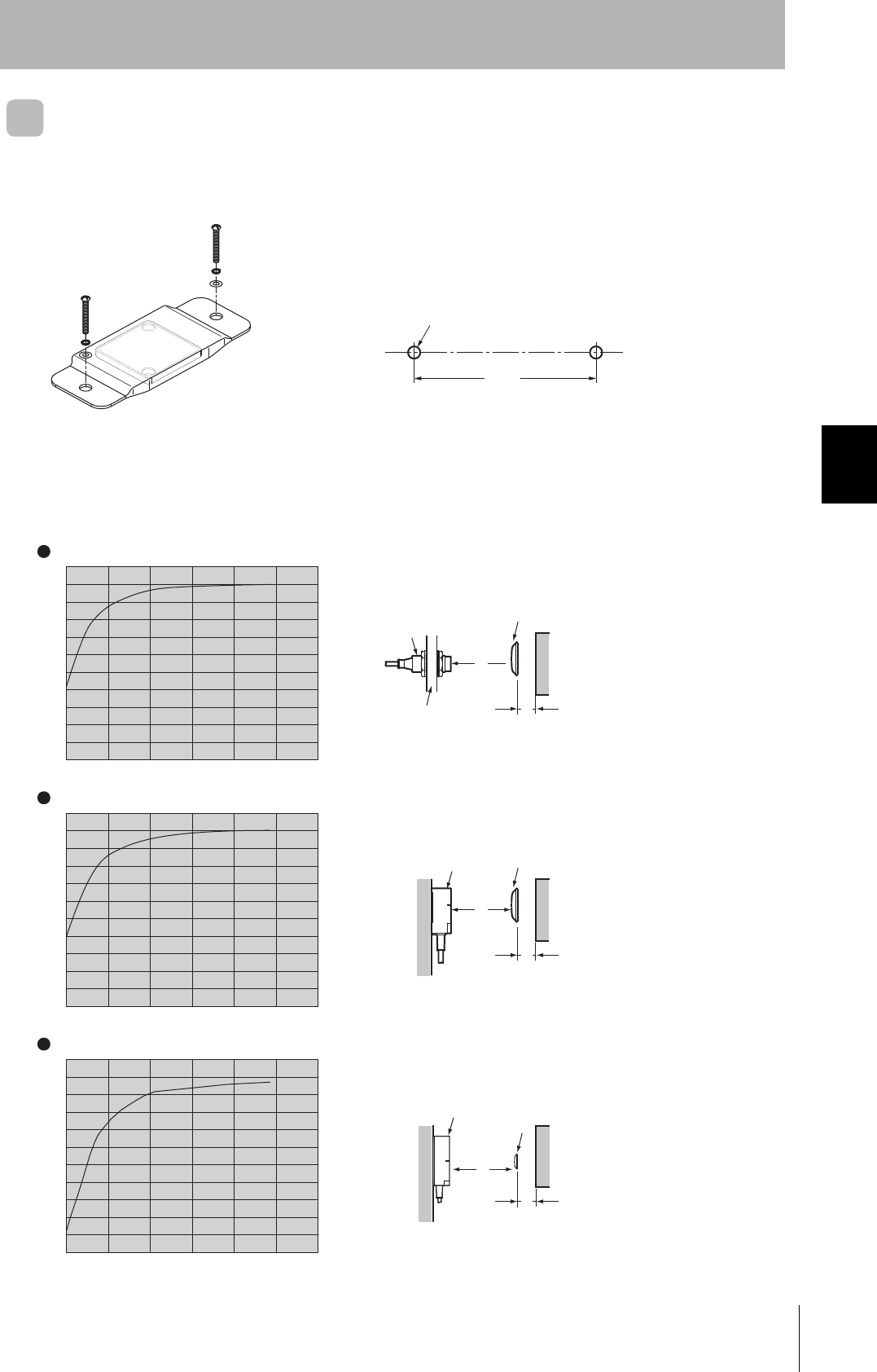
V680-D1KP66T
Tag Installation Direction
Secure the Tag with M3 screws. Tighten the screws to a
torque of 0.6 N·m or less..
Effect of Metal behind Tags (Reference)
The V680-D1KP66T communications distance is reduced if there is any metal material behind the Tag.
If the Tag is to be mounted to metal, then either use a V600-A86 Attachment (sold separately) or insert
a non-metal spacer (such as plastic or resin). The relationship between the distance from the Tag to
the metal surface and the communications distance is shown below.
The Attachment is 10 mm thick, and more than one Attachment can be stacked.
25±0.2
25±0.2
Two, M3
X
Y
M3 countersunk screw
V600-A86 Attachment Installation
0
10
20
30
40
50
60
70
80
90
100
10 20 30 40 50 (mm)
(%)
0
10
20
30
40
50
60
70
80
90
100
10 20 30 40 50 (mm)
(%)
V680-HS52 and V680-D1KP66T
V680-HS63 and V680-D1KP66T
X
Y
Tag
Communica-
tions
distance
Antenna
The communications distance without
metal is 100%.
Antenna Tag
Distance to metal (x)
Distance to metal (x)
Communica-
tions
distance
Metal on back
Metal on back
Metal
The communications distance without
metal is 100%.
Metal
0
10
20
30
40
50
60
70
80
90
100
10 20 30 40 50 (mm)
(%)
V680-HS65 and V680-D1KP66T
Distance to metal (x)
The communications distance without
metal is 100%.
X
Y
Antenna
Tag
Communica-
tions
distance
Metal on back
Metal
Install so that the mounting holes are aligned.

70
Section 4 Installing Tags
RFID System
User's Manual
Section 4
Installation
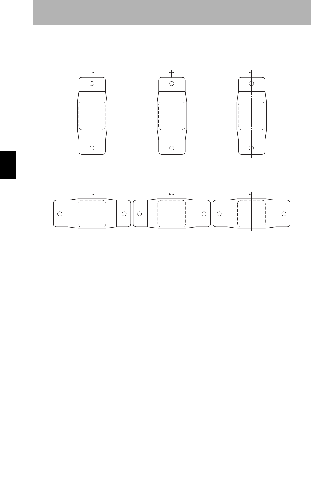
Mutual Interference with Tags (Reference)
To prevent malfunctioning due to mutual interference when using more than one Tag, leave sufficient
space between them as shown in the following diagram.
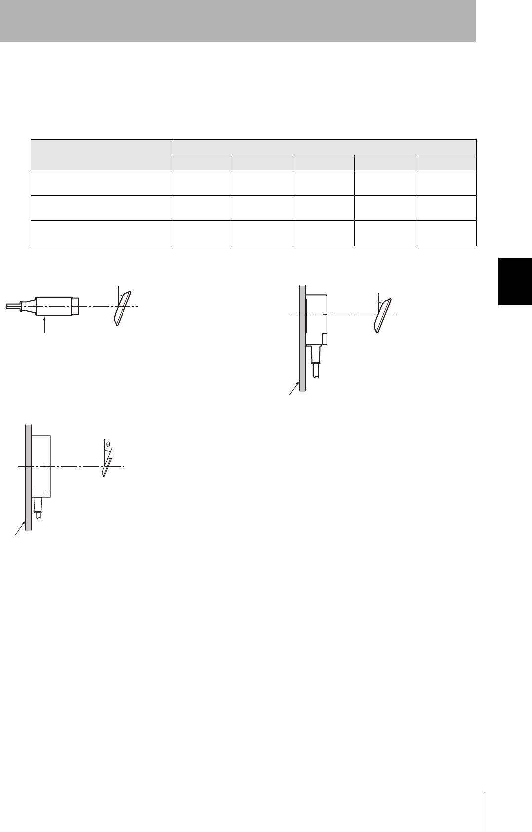
Influence of Tag Angle (Reference)
Install Antennas and Tags as close to parallel to each other as possible. Communications are possible
even when an Antenna and a Tag are mounted at an angle, but the communications distance will be
shortened. The relation between the angle and the communications distance is shown below.
Percentage Drop in Communications Distance According to Angle of V680-D1KP66T
Tag angle (θ°)
010 20 30 40
V680-HS52 and V680-D1KP66T 0% -1% -2% -4% -7%
V680-HS63 and V680-D1KP66T 0% -2% -3% -5% -9%
V680-HS65 and V680-D1KP66T 0% -1% -3% -6% -11%
• V680-HS52 and V680-D1KP66T • V680-HS63 and V680-D1KP66T
• V680-HS65 and V680-D1KP66T
100 mm min. 100 mm min.
Antenna
Tag
θ
Antenna
Tag
θ
Non-Metallic material
Antenna
Tag
θ
Metal
71
RFID System
User's Manual
Section 4 Installing Tags
Section 4
Installation
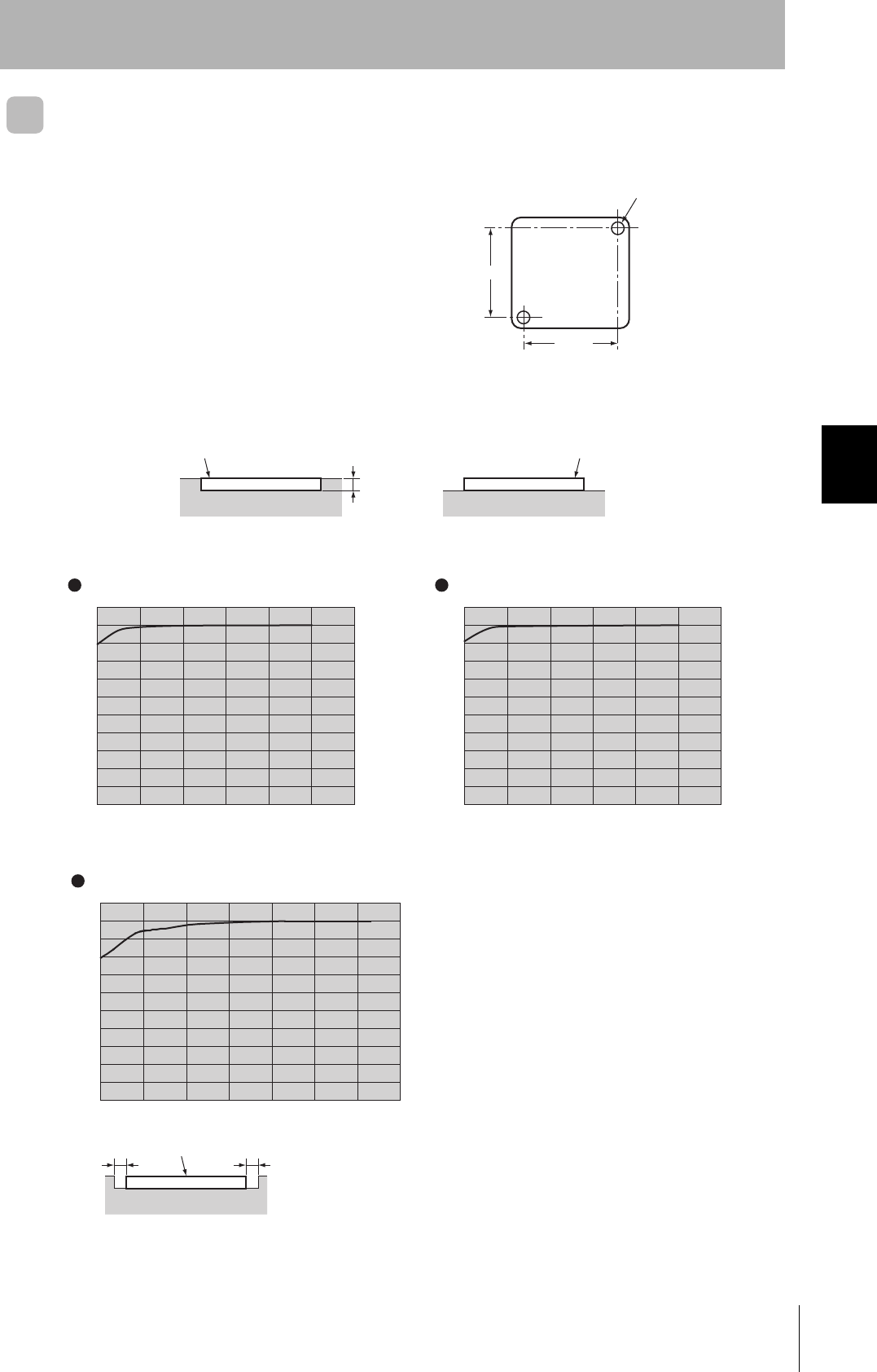
V680-D1KP66MT
Tag Installation Direction
Mount the V680-D1KP66MT to a metal surface, and
secure the Tag with M3 screws. Tighten the screws to a
torque of 0.6 N⋅m or less.
Effect of Surrounding Metals
The V680-D1KP66MT can be surface-mounted or it can be embedded in metal. If it is embedded in
metal, the height of the metal casing must not exceed that of the Tag.
25±0.2
25±0.2
Two, M3
3.5 mm max.
Metal casing
Embedded
Metal casing
Surface-mounted
Ta gTa g
0
10
20
30
40
50
60
70
80
90
100
10 20 30 40 50 (mm)
(%)
Metal case
Tag
xx
V680-HS63 and V680-D1KP66MT
0
10
20
30
40
50
60
70
80
90
100
10 20 30 40 50 (mm)
(%)
V680-HS52 and V680-D1KP66MT
The communications distance without
metal is 100%.
Distance to metal (x) Distance to metal (x)
The communications distance without
metal is 100%.
10 20 30 40 50 60 (mm)0
10
20
30
40
50
60
70
80
90
100
(%)
V680-HS65 and V680-D1KP66MT
The communications distance without
metal is 100%.
Distance to metal (x)
72
Section 4 Installing Tags
RFID System
User's Manual
Section 4
Installation
Mutual Interference with Tag (Reference)
To prevent malfunctioning due to mutual interference when using more than one Tag, leave sufficient
space between them as shown in the following diagram.
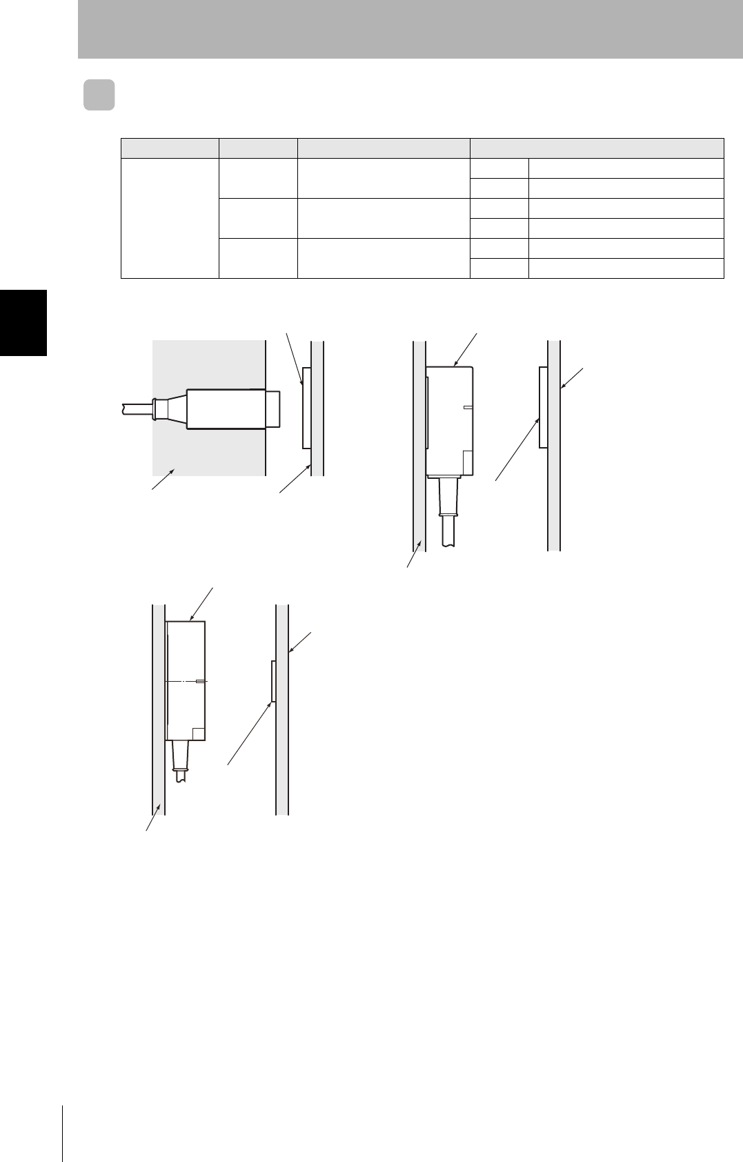
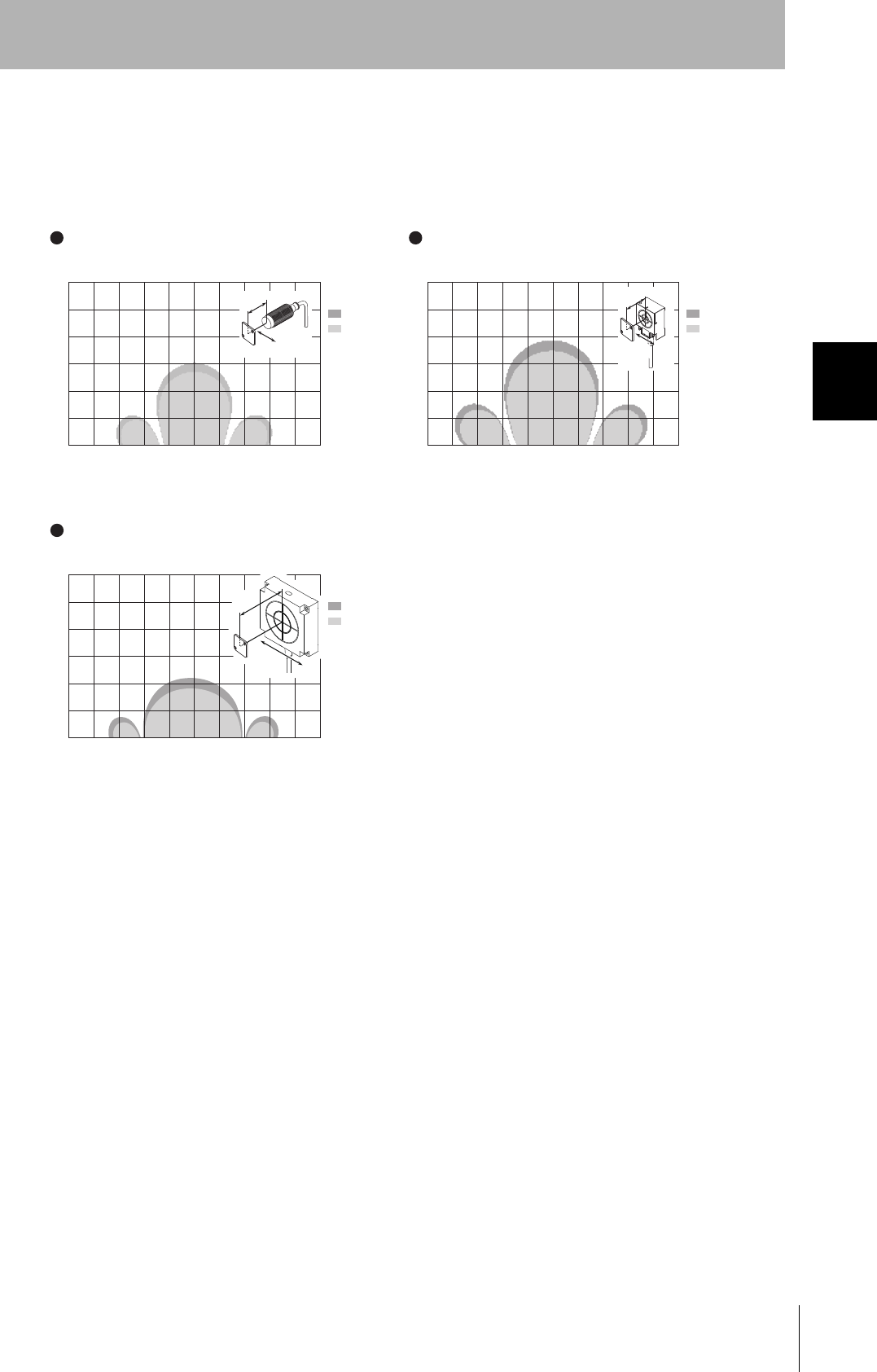
Influence of Tag Angle (Reference)
Install Antennas and Tags as close to parallel to each other as possible. Communications are possible
even when an Antenna and a Tag are mounted at an angle, but the communications distance will be
shortened. The relation between the angle and the communications distance is shown below.
Percentage Drop in Communications Distance According to Angle of V680-D1KP66MT
Tag angle (θ°)
010 20 30 40
V680-HS52 and V680-D1KP66MT
(Metal: Steel) 0% -1% -2% -5% -9%
V680-HS63 and V680-D1KP66MT
(Metal: Steel) 0% -1% -4% -7% -13%
V680-HS65 and V680-D1KP66MT
(Metal: Steel) 0% -1% -6% -15% -
-: The measurement is no possible because the Tag comes in contact with the Antenna.
• V680-HS52 and V680-D1KP66T (Metal: Steel) • V680-HS63 and V680-D1KP66T (Metal: Steel)
• V680-HS65 and V680-D1KP66T (Metal: Steel)
100 mm min. 100 mm min.
Antenna
Tag
θ
Antenna
Tag
θ
Non-Metallic material
Antenna
Tag
θ
Metal
73
RFID System
User's Manual
Section 4 Installing Tags
Section 4
Installation
V680-D1KP66T-SP
Tag Installation Direction
Mount the ID Tags with M5 screws and washers.Tightening torque: 1.2 N.m.
There are no restrictions to the mounting direction of the ID Tags or the direction of movement for Antennas.
Effect of Metal behind Tags (Reference)
Mounting ID Tags to metal workpieces or palettes will affect the communications capabilities. Place non-metal-
lic parts (e.g., plastic or resin) between the metallic parts by referring to the following relationship between the
distance between the ID Tag and the metallic body versus the communications distance.
Mounting hole dimensions
Two, M5
80±0.2
Y
Antenna
Communi-
cations
distance
X
Tag
Y
Communi-
cations
distance
Antenna
Metal X
Tag
X
Y
Antenna
Tag
Communi-
cations
distance
0
10
20
30
40
50
60
70
80
90
100
10 20 30 40 50 (mm)
(%)
V680-HS52 and V680-D1KP66T-SP
The communications distance without
metal is 100%.
Distance to metal (x)
0
10
20
30
40
50
60
70
80
90
100
10 20 30 40 50 (mm)
(%)
V680-HS63 and V680-D1KP66T-SP
The communications distance without
metal is 100%.
Distance to metal (x)
0
10
20
30
40
50
60
70
80
90
100
10 20 30 40 50 (mm)
(%)
V680-HS65 and V680-D1KP66T-SP
The communications distance without
metal is 100%.
Distance to metal (x)
Metal on backMetal
Metal
Metal on back
Metal
74
Section 4 Installing Tags
RFID System
User's Manual
Section 4
Installation
Mutual Interference with Tag (Reference)
To prevent malfunctioning due to mutual interference when using more than one Tag, leave sufficient
space between them as shown in the following diagram.
100 mm min. 100 mm min.
100 mm min. 100 mm min.
75
RFID System
User's Manual
Section 4 Installing Tags
Section 4
Installation
Influence of Tag Angle (Reference)
Install Antennas and Tags as close to parallel to each other as possible. Communications are possible
even when an Antenna and a Tag are mounted at an angle, but the communications distance will be
shortened. The relation between the angle and the communications distance is shown below.
Percentage Drop in Communications Distance According to Angle of V680-D1KP66T-SP
Tag angle (θ°)
010 20 30 40
V680-HS52 and V680-D1KP66T-SP 0% -1% -2% -4% -7%
V680-HS63 and V680-D1KP66T-SP 0% -2% -3% -5% -9%
V680-HS65 and V680-D1KP66T-SP 0% -1% -3% -6% -11%
• V680-HS52 and V680-D1KP66T-SP • V680-HS63 and V680-D1KP66T-SP
• V680-HS65 and V680-D1KP66T-SP
Antenna Tag
θ
Antenna
Tag
θ
Non-Metallic material
Antenna
Tag
Metal
76
Section 4 Installing Tags
RFID System
User's Manual
Section 4
Installation
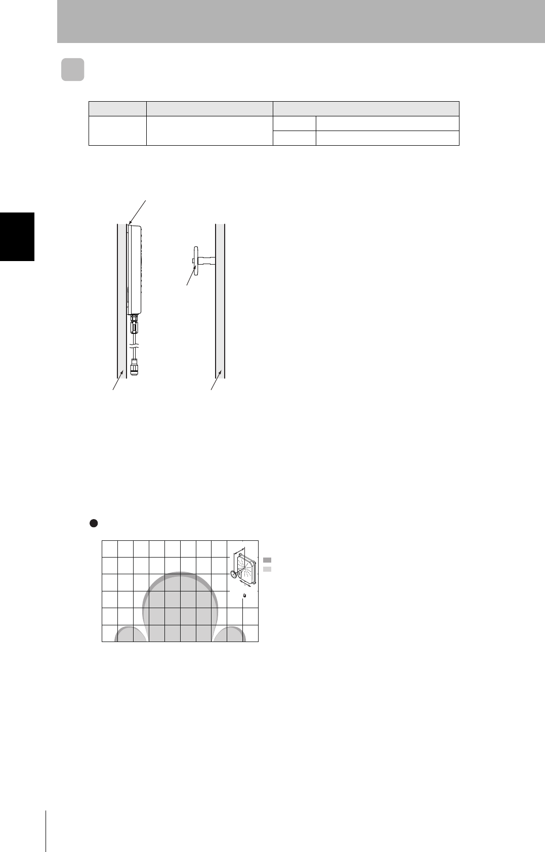
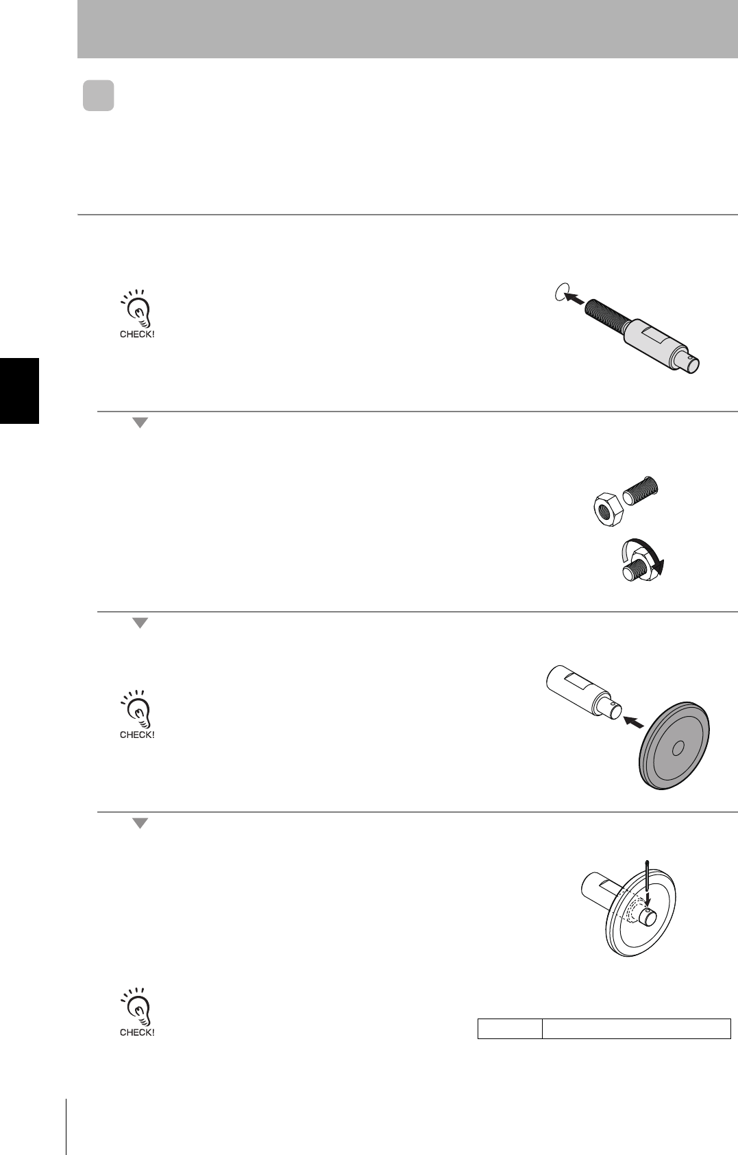
V680-D1KP58HT
Tag Installation Direction
The Tags have a limited life span. Therefore, install them in locations in which they can be easily
replaced. Use the following procedure to mount the V680-A80 Attachment when required.
1. Mount the Attachment to the workpiece.
Use a tightening torque of 21 to 42 N·m.
2. Tighten the lock nut.
3. Mount the Tag to the Attachment.
The Tag can be mounted in either direction.
Insert the split pin into the 3.2-dia. hole and open the tip of the pin to secure.
Two nuts and one split pin are provided with the V680-A80 Attachment. Replacement split pins must be
provided by the user.
Split pin Nominal: 3.2 mm × 20 mm (length)
77
RFID System
User's Manual
Section 4 Installing Tags
Section 4
Installation
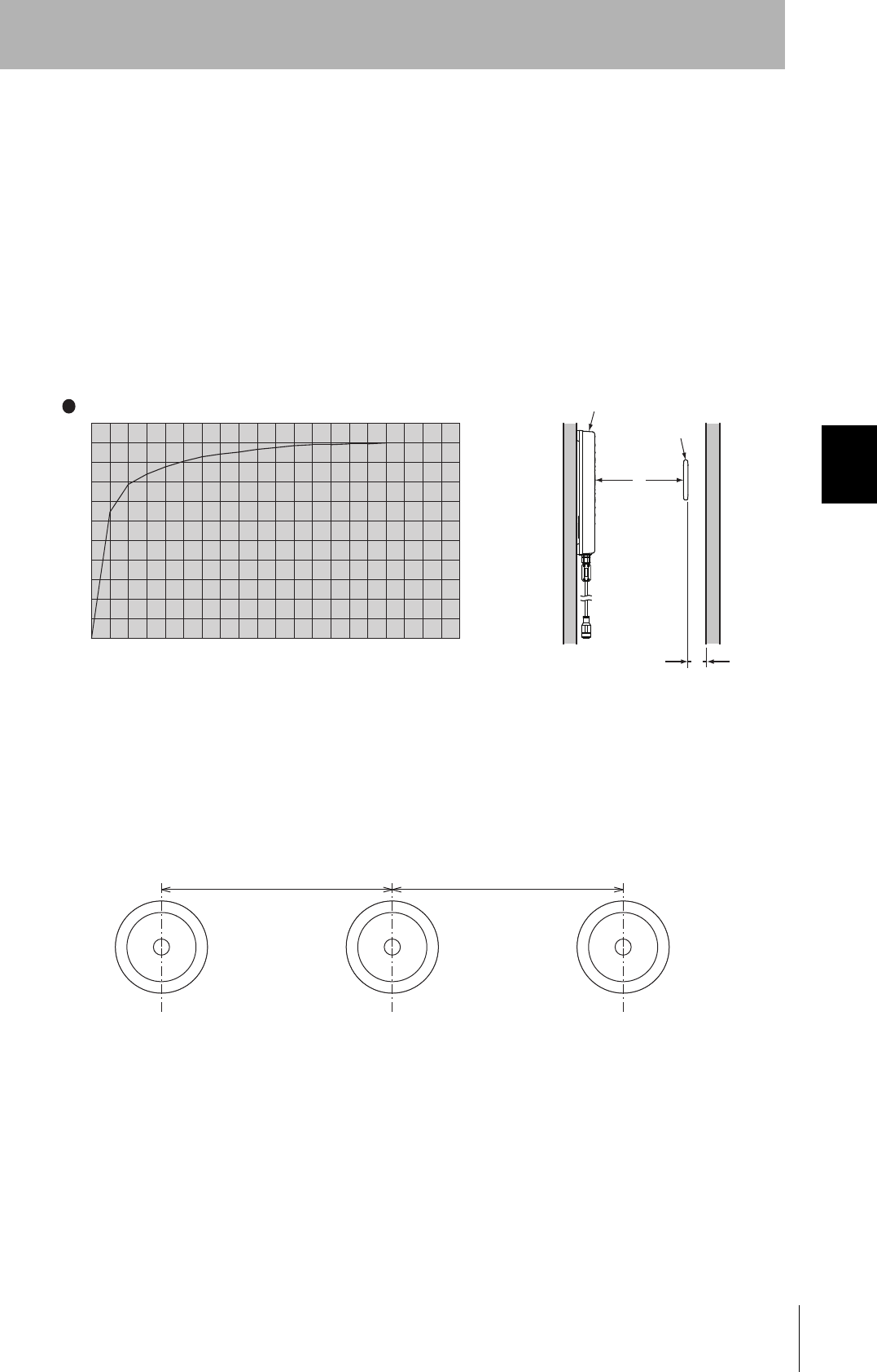
Influence of Metal Behind Tag (Reference)
Take the influence of metal behind Tags into consideration when mounting them.
The communications distance is adversely affected if there is any metal material around the Tag. The
degree of influence depends on the type, size, and shape of the material around the Tag. The following
graphs show the influence of metal objects behind the Tag for reference.
• Influence of Metal
The following diagram shows the rate of reduction in the communications distance when metal is
located behind the Tag. The horizontal axis in the diagram indicates the distance between the Tag and
the metal plate, and the vertical axis indicates the relative communications distance at 100% without a
metal plate, i.e, the rate of reduction in communications distance.
Material: Steel (t = 1.5 mm)
Shape: 295 mm × 295 mm
Mutual Interference with Tag (Reference)
Provide the mounting distances indicated below to prevent malfunctions due to mutual interference
when using multiple Tags.
0
10
20
30
40
50
60
70
80
90
100
10 20 30 40 50 (mm)
(%)
60 70 80 90 100110120130140150160170180190
Y
Communi-
cations
distance
X
Antenna
Tag
V680-H01-V2 and V680-D1KP58HT
The communications distance without
metal is 100%.
Distance to metal (x)
Metal on back
250mm min. 250mm min.
78
Section 4 Installing Tags
RFID System
User's Manual
Section 4
Installation
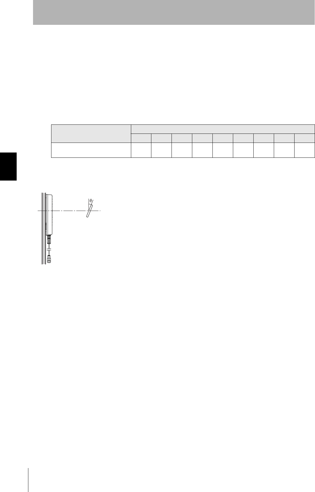
Influence of Tag Angle (Reference)
The maximum communications distance can be obtained when the Antenna and Tag are installed in
parallel. When the Tag is installed on an angle, the communications distance is reduced. Consider the
effect of the Tag angle when installing the Tag. As reference data, the following diagram shows the rate
of reduction in communications distance according to the Tag angle. The horizontal axis indicates the
angle when the Tag surface and Antenna surface are in parallel at 0°. The vertical axis indicates the
relative communications distance when the angle is 0° at 100%, i.e., the rate in reduction of the com-
munications distance.
Percentage Drop in Communications Distance According to Angle of V680-D1KP58HT
Tag angle (θ°)
010 20 30 40 50 60 70 80
V680-H01-V2 and V680-D1KP58HT 0% -2% -5% -10% -15% -20% -30% -40% -60%
• V680-H01-V2 and V680-D1KP58HT
Antenna
Tag
Non-metallic material

Section 5 Chemical Resistance
79
RFID System
User's Manual
Section 5
Chemical Resistance
Chemical Resistance of the Antennas 80
Chemical Resistance of Tags 81
Degree of Protection 85
80
Section 5 Chemical Resistance of the Antennas
RFID System
User's Manual
Section 5
Chemical Resistance
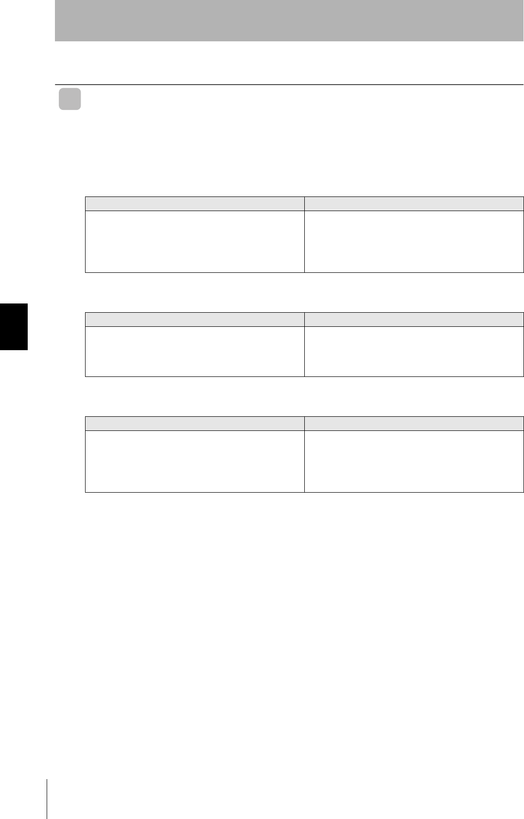
Chemical Resistance of the Antennas
Applicable Models
ABS resin is used for case material and epoxy resin for filling material. Refer to the following lists and do not
use chemicals that affect ABS and epoxy resin.
Chemicals That Cause Deformations, Cracks, Etc.
Chemicals That May Cause Discoloration, Swelling, Etc.
Chemicals That Do Not Affect ABS Resin or Epoxy Resin
Note: The above results are from tests conducted a room temperature (23°C). Even if the chemicals
do not affect the ABS or epoxy resins at room temperature, they may affect the resins at higher
or lower temperatures. Check the chemicals carefully in advance.
V680-HS51 V680-HS52-W/R V680-HS63-W/R V680-HS65-W/R V680-H01-V2
ABS resin Epoxy resin
Trichlene, acetone, xylene, toluene, gasoline, creosol,
methylene chloride, phenol, cyclohexane, aqua regia,
chromic acid, sulfuric acid (90% RT), methyl ethyl
ketone, aniline, nitrobenzine, monochlorobenzine,
pyridine, nitric acid (60% RT), formic acid (80% RT)
Aqua regia, chromic acid, sulfuric acid (90% RT),
nitric acid (60% RT), ammonia solution, acetone,
methylene chloride, phenol
ABS resin Epoxy resin
Hydrochloric acid, alcohol, Freon, sodium hydroxide,
hydrogen peroxide, benzine, sulfuric acid (10% RT),
nitric acid (10% RT), phosphoric acid (85% RT),
ammonia solution
Sulfuric acid (10% RT), nitric acid (10% RT), hydrochlo-
ric acid (30% RT), acetic acid (50% RT), oxalic acid,
calcium hydroxide, benzine, creosol, alcohol, cyclohex-
ane, toluene, xylene, benzine, grease
ABS resin Epoxy resin
Ammonia, kerosine, mineral oil, developer, Yushiroken
S50, Chemi-Cool Z, Velocity No. 3, Yushiroken EEE-
30Y, petroleum, grease, acetic acid, oxalic acid, cal-
cium hydroxide, phosphoric acid (30% RT), hydrochlo-
ric acid (10% RT), potassium hydroxide
Ammonia, hydrochloric acid (10% RT), potassium
hydroxide, petroleum, gasoline, Yushiroken S50,
Chemi-Cool Z, Velocity No. 3, Yushiroken EEE-30Y
81
RFID System
User's Manual
Section 5 Chemical Resistance of Tags
Section 5
Chemical Resistance
Chemical Resistance of Tags
Applicable Model
PPS resin is used for case material and epoxy resin for filling material. Refer to the following lists and do not
use chemicals that affect PPS and epoxy resin.
Tags cannot be used in applications with explosion-proof specifications.
Chemicals That Cause Deformations, Cracks, Etc.
Chemicals That May Cause Discoloration, Swelling, Etc.
Chemicals that Do Not Affect PPS Resin or Epoxy Resin
Note: The above results are from tests conducted a room temperature (23°C). Even if the chemicals
do not affect the PPS or epoxy resins at room temperature, they may affect the resins at higher
or lower temperatures. Check the chemicals carefully in advance.
V680-D1KP52MT
PPS resin Epoxy resin
Aqua regia Aqua regia, chromic acid, sulfuric acid (90% RT),
nitric acid (60% RT), ammonia solution, acetone,
methylene chloride, phenol
PPS resin Epoxy resin
Nitric acid (60% RT) Sulfuric acid (10% RT), nitric acid (10% RT), hydrochlo-
ric acid (30% RT), acetic acid (50% RT), oxalic acid,
calcium hydroxide, benzine, creosol, alcohol, cyclohex-
ane, toluene, xylene, benzine, grease
PPS resin Epoxy resin
Hydrochloric acid (37%RT), sulfuric acid (98%RT),
nitric acid (40%RT), Hydrogen fluoride solution
(40%RT), chromic acid (40%RT), hydrogen peroxide
(28%RT), sodium hydroxide solution (60%RT),
ammonia solution (28%RT), sodium chloride (10%RT),
sodium carbonate (20%RT), sodium hypochlorite,
phenol solution (5%RT), glacial acetic acid, acetic acid,
oleic acid, Methyl alcohol (95%RT), ethyl alcohol
(95%RT), Ethyl acetate, sebacic acid, diethylhexyl,
acetone, diethyl ether, n-heptane, 2-2-4 trimethylpen-
tane, benzine, toluene, aniline, mineral oil, gasoline,
insulating oil, dichloroethylene, carbon tetrachloride
Ammonia, hydrochloric acid (10% RT), potassium
hydroxide, petroleum, gasoline, Yushiroken S50,
Chemi-Cool Z, Velocity No. 3, Yushiroken EEE-30Y,
methyl ethyl ketone, sodium hydroxide (10%RT)
82
Section 5 Chemical Resistance of Tags
RFID System
User's Manual
Section 5
Chemical Resistance
Applicable Models
PPS resin is used for case material. Refer to the following lists and do not use chemicals that affect
PPS and epoxy resin.
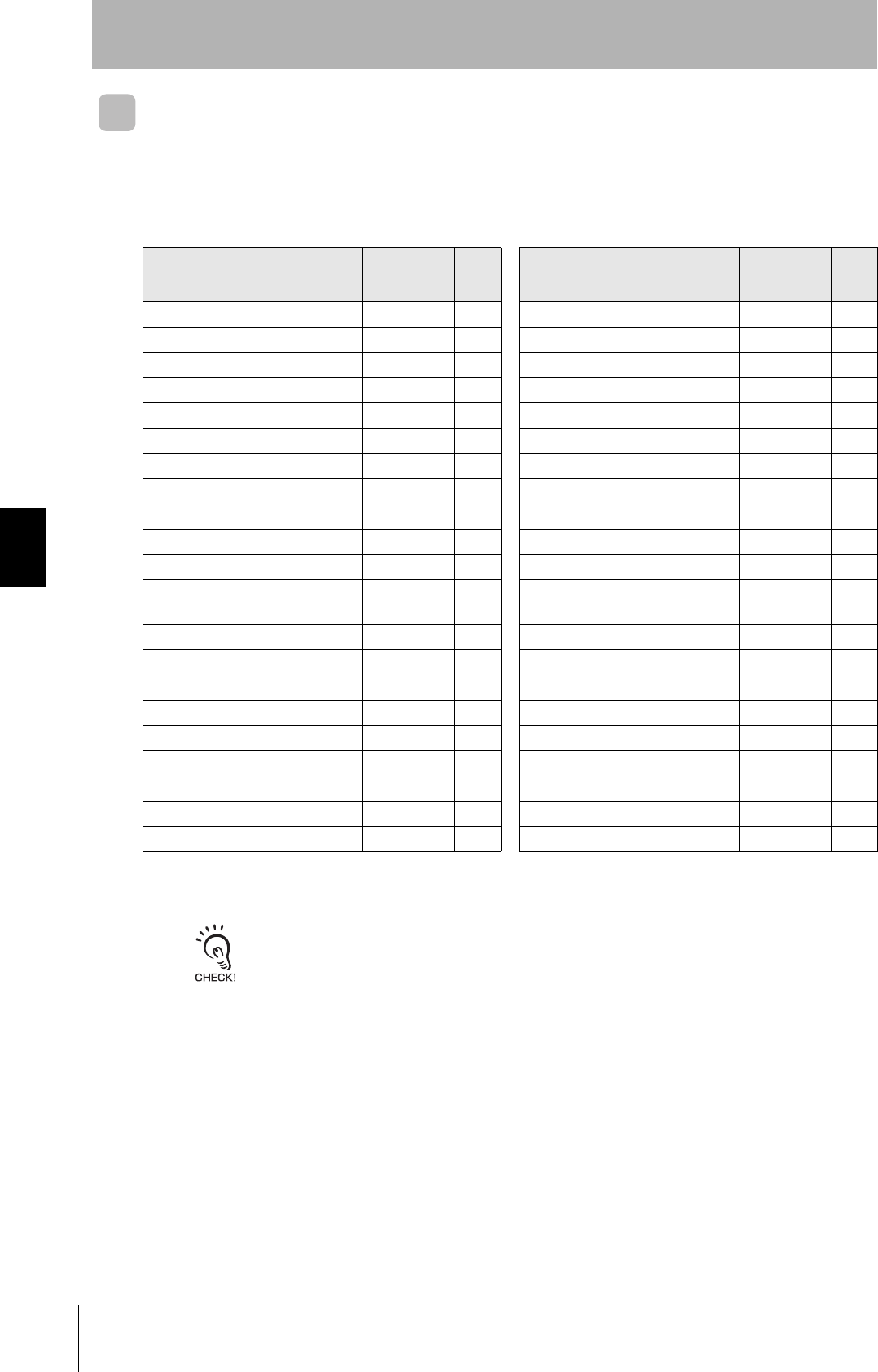
The above table shows the extent of changes in PPS resin exposed to each chemical at room temperature
and at 90°C. If actual chemicals, concentrations, and temperatures are different from those shown in the
tables, always conduct tests under the actual conditions in which the Tags are to be used.
V680-D1KP66T/66MT V680-D1KP58HT
Chemical
At room
tempera-
ture
At
90°CChemical
At room
tempera-
ture
At
90°C
Hydrochloric acid 37% A A Sodium hypochlorite AA
10% A A Phenol solution 5% A A
Sulfuric acid 98% A B Glacial acetic acid AA
50% A A Acetic acid AA
30% A A Oleic acid AA
3% A A Methyl alcohol 95% A A
Nitric acid 60% B C Ethyl alcohol 95% A A
40% A B Ethyl acetate AA
10% A A Sebacic acid diethylhexyl AA
Hydrogen fluoride solution 40% A A Acetone AA
Chromic acid 40% A A Diethyl ether AA
Hydrogen peroxide solu-
tion 28% A B n-heptane AA
3% A A 2-2-4 trimethylpentane AA
Sodium hydroxide solution 60% A A Benzene AA
10% A A Toluene AA
1% A A Aniline AA
Ammonia solution 28% A B Mineral oil AA
10% A B Gasoline AA
Sodium chloride 10% A A Insulating oil AA
Sodium carbonate 20% A A Dichloroethylene AA
2% A A Carbon tetrachloride AA
A: Has no adverse effect, B: May cause discoloration, swelling, etc., C: Causes deformation, cracks, etc.
83
RFID System
User's Manual
Section 5 Chemical Resistance of Tags
Section 5
Chemical Resistance
Applicable Models
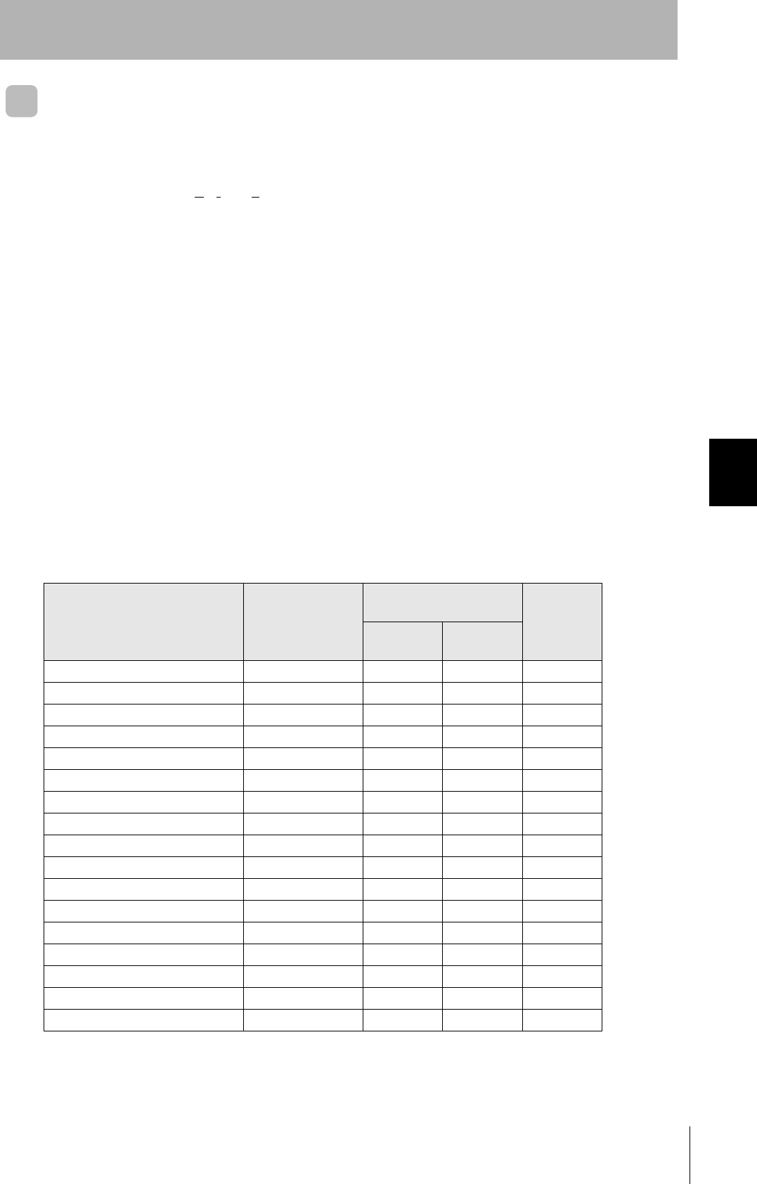
Chemical Resistance of Fluoroplastic PFA (Reference)
PFA: Tetrafluorethylene-Perfluoroalkylvinyletheir Copolymer
Fluoroplastic PFA does not react with most chemicals except molten alkali metal, hot pressurized
fluorine (F2), and some halogen derivatives. The following tables show the results of tests in which PFA
was soaked in or exposed to commonly used organic and inorganic chemicals. In these tests, a
compression-molded test piece (1.3 mm thick) was soaked in the chemical at a specified temperature
for a week (168 houre) and taken out of the chemical, then the weight change, tensile strength, and
elongation of the test piece were immediately measured. If the change in the tensile strength is 15 % or
less, the cange in the elongation is 10 % or less, and the increase in the weight is less than 0.5 %, the
results of the test can be considered normal.
If PFA is exposed to trichloroacetic acid, tri-n-butyl phosphate, perchloroethylene, carbon thtrachloride,
and other liquids (which easily make resin surfaces wet) at a high temperature, it tends to increase its
weight due to absorption and reduce its tensile strength. Even when PFA absorbs chemicals and sol-
vents, its molecular structure will not change, If, however, PFA is subject to temperature or pressure
changes or mechanical damage when it has absorbed chemicals, the chemicals will repeatedly
expand and contract inside pfa, causing mechanical problems such as cracks and bulging. In fact, this
problem occurs with any kind of plastic.
Inorganic Chemicals
V680-D1KP66T-SP
Chemical name
Test
temperature
(°C)
Resulting characteristics
(%) Weight
increase
rate (%)
Tensile
strength Elongation
concentrated hydrochloric acid 120 98 100 0.0
Concentrated sulfuric acid 120 95 98 0.0
Hydrofluoric acid (60%) 23 99 99 0.0
Fuming sulfuric acid 23 95 96 0.0
Aqua regia 120 99 100 0.0
Chromic acid (50%) 120 93 97 0.0
Consentrated nitric acid 120 95 98 0.0
Fuming nitric acid 23 99 99 0.0
Concentrated ammonia solution 66 98 100 0.0
Caustic soda (50%) 120 93 99 0.4
Hydrogen peroxide solution (30%) 23 93 95 0.0
Bromine 23 99 100 0.5
Chlorine 120 92 100 0.5
Ferrous chloride (25%) 100 93 98 0.0
Zinc chloride (25%) 100 96 100 2.7
Chlorosulfonic acid 151 91 100 2.7
Concentrated phosphoric acid 100 93 100 0.0
84
Section 5 Chemical Resistance of Tags
RFID System
User's Manual
Section 5
Chemical Resistance
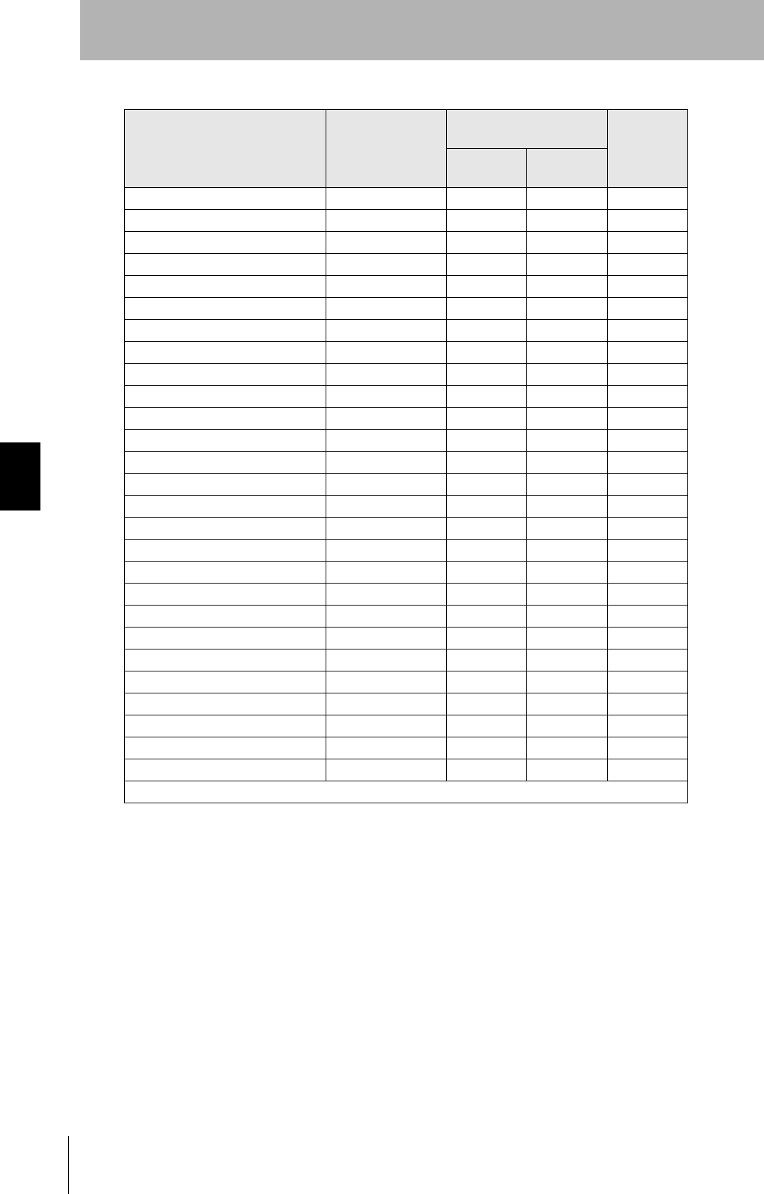
Organic Chemicals
Chemical name
Test
temperature
(°C)
Resulting characteristics
(%) Weight
increase
rate (%)
Tensile
strength Elongation
Glacial acetic acid 118 95 100 0.4
Acetic anhydride 139 91 99 0.3
Trichloroacetic acid 196 90 100 2.2
Isooctane 99 94 100 0.7
Naphtha 100 91 100 0.5
Mineral oil 180 87 95 0.0
Toluene 110 88 100 0.7
o-creosol 191 92 96 0.2
Nitrobenzene 210 90 100 0.3
Benzyl alcohol 205 93 99 0.3
Aniline 185 94 100 0.3
n-butylamine 78 86 97 0.4
Ethylenediamine 117 96 100 0.1
Tetrahydrofuran 66 88 100 0.1
Benzaldehyde 179 90 99 0.5
Cyclohexane 156 92 100 0.4
Methyl ethyl ketone 80 90 100 0.4
Acetophenone 202 90 100 0.6
Dimethylphtalate 200 98 100 0.3
n-butyl acetate 125 93 100 0.5
Tri-n-butyl phosphate 200 91 100 2.0
Methylene chloride 40 94 100 0.8
Perchloroethylene 121 86 100 2.0
Carbon tetrachloride 77 87 100 2.3
Dimethyl formamide 154 96 100 0.2
Dimethyl sulfoxide 189 95 100 0.1
Dioxane 101 92 100 0.6
Reference: Fluoroplastics Handbook, The Nikkan Kogyo Shimbun Ltd. (Takaomi Satogawa)
85
RFID System
User's Manual
Section 5 Degree of Protection
Section 5
Chemical Resistance
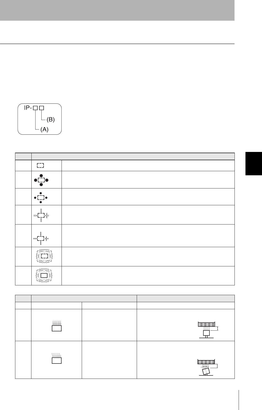
Degree of Protection
Ingress protection degrees (IP-@@) are determined by the following tests. Be sure to check the sealing capa-
bility under the actual operating environment and conditions before actual use.
IP indicates the ingress protection symbol.
IEC (International Electrotechnical Commission) Standards
IEC 60529: 2001
(A) First Digit: Degree of Protection from Solid Materials
(B) Second Digit: Degree of Protection Against Water
Degree Degree
0No protection
1
Protects against penetration of any solid object such as a hand that is 50 mm or more in diameter.
2
Protects against penetration of any solid object, such as a finger, that is 12.5 mm or more in diame-
ter.
3
Protects against penetration of any solid object, such as a wire, that is 2.5 mm or more in diameter.
4
Protects against penetration of any solid object, such as a wire, that is 1 mm or more in diameter.
5
Protects against penetration of dust of a quantity that may cause malfunction or obstruct the safe
operation of the product.
6
Protects against penetration of all dust.
Degree Protection Test method (with pure water)
0 No protection Not protected against water. No test
1 Protection against water
drops
Protects against vertical drops
of water towards the product.
Water is dropped vertically towards the product from
the test machine for 10 min.
2 Protection against water
drop
Protects against drops of
water approaching at a maxi-
mum angle of 15°to the left,
right, back, and front from ver-
tical towards the product.
Water is dropped for 2.5 min each (i.e., 10 min in total)
towards the product inclined 15° to the left, right, back,
and front from the test machine.
50 mm dia.
12.5 mm dia.
2.5 mm
1 mm
200 mm
200 mm
15˚
86
Section 5 Degree of Protection
RFID System
User's Manual
Section 5
Chemical Resistance
Note: OMRON Test Method
Usage conditions: 10 m or less under water in natural conditions
1.No water ingress after 1 hour under water at 2 atmospheres of pressure.
2.Communications performance must be met after 100 repetitions of 30 minutes in 5°C water and 30
minutes in 85°C water.
Oil resistance (OMRON in-house standard)
Note: This OMRON in-house standard confirms resistance to cutting and other oils. It is equivalent to the
former JEM standard.
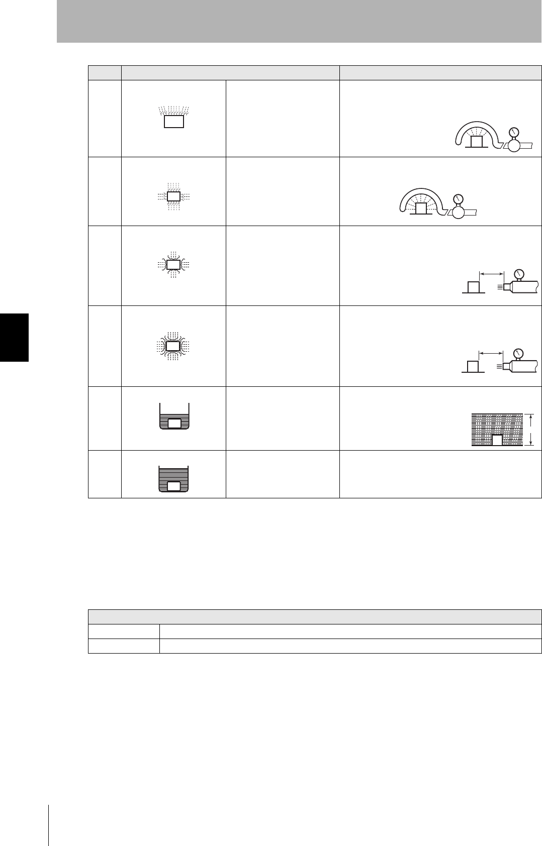
3 Protection against sprin-
kled water
Protects against sprinkled
water approaching at a maxi-
mum angle of 60° from verti-
cal towards the product.
Water is sprinkled for 10 min at a maximum angle of
60° to the left and right from vertical from the test
machine.
4 Protection against water
spray
Protects against water spray
approaching at any angle
towards the product.
Water is sprayed at any angle towards the product for
10 min from the test machine.
5 Protection against water jet
spray
Protects against water jet
spray approaching at any
angle towards the product.
Water is jet sprayed at any angle towards the product
for 1 min per square meter for at least 3 min in total
from the test machine.
6 Protection against high
pressure water jet spray
Protects against high-pres-
sure water jet spray approach-
ing at any angle towards the
product.
Water is jet sprayed at any angle towards the product
for 1 min per square meter for at least 3 min in total
from the test machine.
7 Protection underwater Resists the penetration of
water when the product is
placed underwater at speci-
fied pressure for a specified
time.
The product is placed 1 m deep in water (if the product
is 850 mm max. in height) for 30 min.
8
(See Note)
Protection underwater Can be used continuously
underwater.
The test method is determined by the manufacturer and
user.
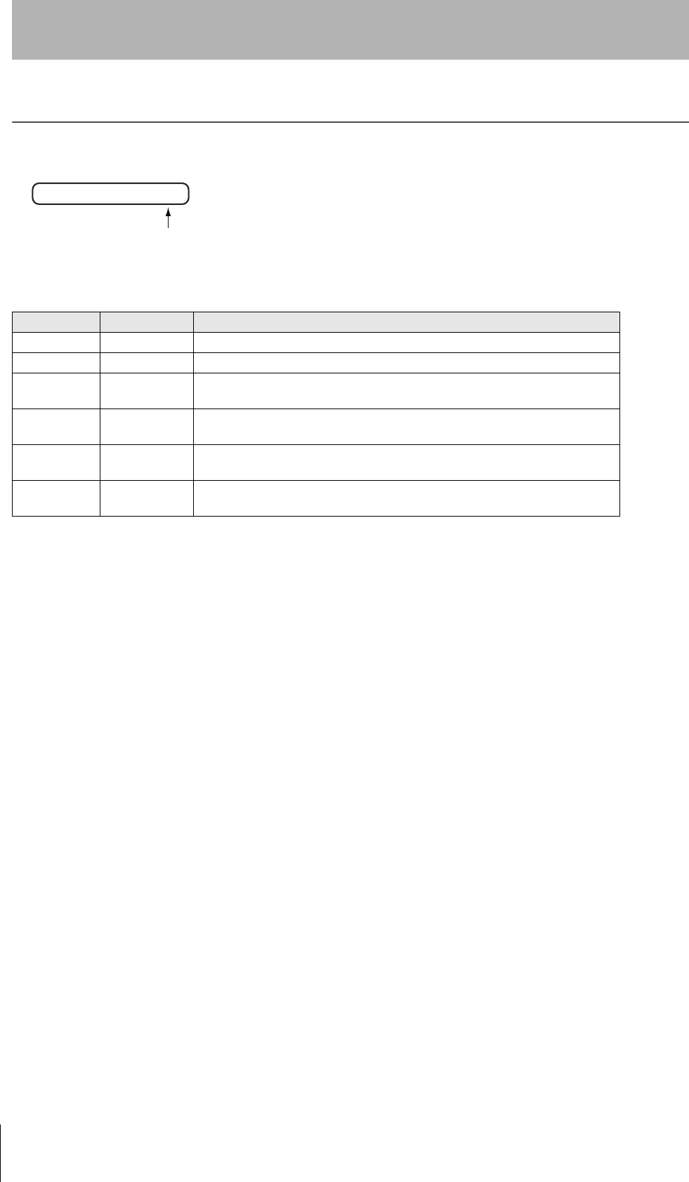
Protection
Oil-resistant No adverse affect from oil drops or oil spray approaching from any direction.
Oil-proof Protects against penetration of oil drops or oil spray approaching from any direction.
Degree Protection Test method (with pure water)
Water rate is 0.07
liter/min per hole.
Water rate is 0.07
liter/min per hole.
2.5 to 3 m
12.5 liter/min
Discharging nozzle: 6.3 dia.
2.5 to 3 m 100 liter/min
Discharging nozzle: 6.3 dia.
1 m

87
RFID System
User's Manual
Section 5 Degree of Protection
Section 5
Chemical Resistance
MEMO
88 RFID System
User's Manual
Revision History
A manual revision code appears as a suffix to the catalog number at the bottom of the front and rear pages.
Revision code Date Revised contents
01 May 2007 Original production
02 July 2007 Added item for V680-HS65 Antenna, and the overseas regulations and standards.
02A September 2007 Added information on metal on back surface of the V680-HS65, corrected Tag
specifications, and made other minor corrections.
03 December 2007 Added item for V680-HS51 Antenna, V680-D1KP66T-SP Tag, the overseas regula-
tions and standards, and made other minor corrections.
03A June 2008 Added item for the overseas regulations and standards, and made other minor
corrections.
04 November 2008 Added item for V680-H01-V2 Antenna, V680-D1KP58HT Tag, and made other minor
corrections.
Cat. No.: Z262-E1-04
Revision code

Authorized Distributor:
In the interest of product improvement,
specifications are subject to change without notice.
Cat. No. Z262-E1-04OMRON Industrial Automation Global: www.ia.omron.com
Printed in Japan
1108-0.3C (0507)
OMRON Corporation
Industrial Automation Company
Regional Headquarters
OMRON EUROPE B.V.
Sensor Business Unit
Carl-Benz-Str. 4, D-71154 Nufringen,
Germany
Tel: (49) 7032-811-0/Fax: (49) 7032-811-199
OMRON ELECTRONICS LLC
One Commerce Drive Schaumburg,
IL 60173-5302 U.S.A.
Tel: (1) 847-843-7900/Fax: (1) 847-843-7787
OMRON ASIA PACIFIC PTE. LTD.
No. 438A Alexandra Road # 05-05/08 (Lobby 2),
Alexandra Technopark, Singapore 119967
Tel: (65) 6835-3011/Fax: (65) 6835-2711
OMRON (CHINA) CO., LTD.
Room 2211, Bank of China Tower,
200 Yin Cheng Zhong Road,
PuDong New Area, Shanghai, 200120, China
Tel: (86) 21-5037-2222/Fax: (86) 21-5037-2200
Sensing Devices Division H.Q.
Industrial Sensors Division
Shiokoji Horikawa, Shimogyo-ku,
Kyoto, 600-8530 Japan
Tel: (81)75-344-7022/Fax: (81)75-344-7107
© OMRON Corporation 2008 All Rights Reserved.