Panasonic Devices Europe 1315 Bluetooth Module User Manual TABLE OF CONTENTS
Panasonic Industrial Devices Europe GmbH Bluetooth Module TABLE OF CONTENTS
Contents
- 1. UserMan
- 2. Updated OEM instruction for module integration
- 3. Updated OEM instruction to design and/or use of antennas KDB 996369 Question 11
- 4. 15_PAN1315 UserMan
Updated OEM instruction to design and/or use of antennas KDB 996369 Question 11
CLASSIFICATION
FCC ID T7V1315
OEM antenna instructions
No.
Instructions_Antenna
REV.
1.0
SUBJECT
Manual according KDB996369 question 11
for host manufactures how to design antennas
PAGE
1 of 4
DATE
12.05.2015
PANASONIC INDUSTRIAL DEVICES EUROPE GMBH
www.pideu.panasonic.de
TABLE OF CONTENTS
1. Trace layout and dimensions including specific design .................................................. 2
1.1. Detailed engineering reference ............................................................................ 2
1.1.1. Answer 11 item 1a: ................................................................................. 2
1.1.2. Answer 11 item 1b, c: .............................................................................. 3
1.1.3. Answer 11 item 1d: ................................................................................. 4
1.1.4. Answer 11 item 2: ................................................................................... 4
1.1.5. Answer 11 item 3: ................................................................................... 4
2. History for this Document .............................................................................................. 4
CLASSIFICATION
FCC ID T7V1315
OEM antenna instructions
No.
Instructions_Antenna
REV.
1.0
SUBJECT
Manual according KDB996369 question 11
for host manufactures how to design antennas
PAGE
2 of 4
DATE
12.05.2015
PANASONIC INDUSTRIAL DEVICES EUROPE GMBH
www.pideu.panasonic.de
1. TRACE LAYOUT AND DIMENSIONS INCLUDING SPECIFIC DESIGN
1.1. DETAILED ENGINEERING REFERENCE
1.1.1. Answer 11 item 1a:
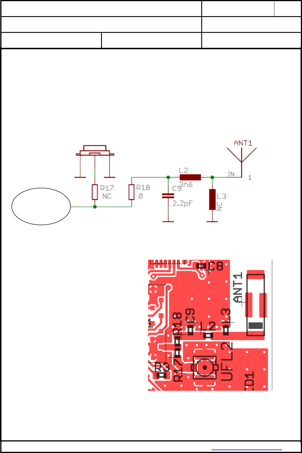
The antenna trace has to be matched to 50ohm impedance. To keep this the recommended
antenna trace has to be used with the following components and design.
Schematic:
If using UFL connector R17 has to be mounted with 0Ohm resistor instead of R18.
Layout of antenna trace:
Trace width 0.9mm
Trace distance to GND 0.2mm
Trace distance to L2 GND 35µm
Trace length shall not exceed 2cm
Antenna
Pin of
module
CLASSIFICATION
FCC ID T7V1315
OEM antenna instructions
No.
Instructions_Antenna
REV.
1.0
SUBJECT
Manual according KDB996369 question 11
for host manufactures how to design antennas
PAGE
3 of 4
DATE
12.05.2015
PANASONIC INDUSTRIAL DEVICES EUROPE GMBH
www.pideu.panasonic.de
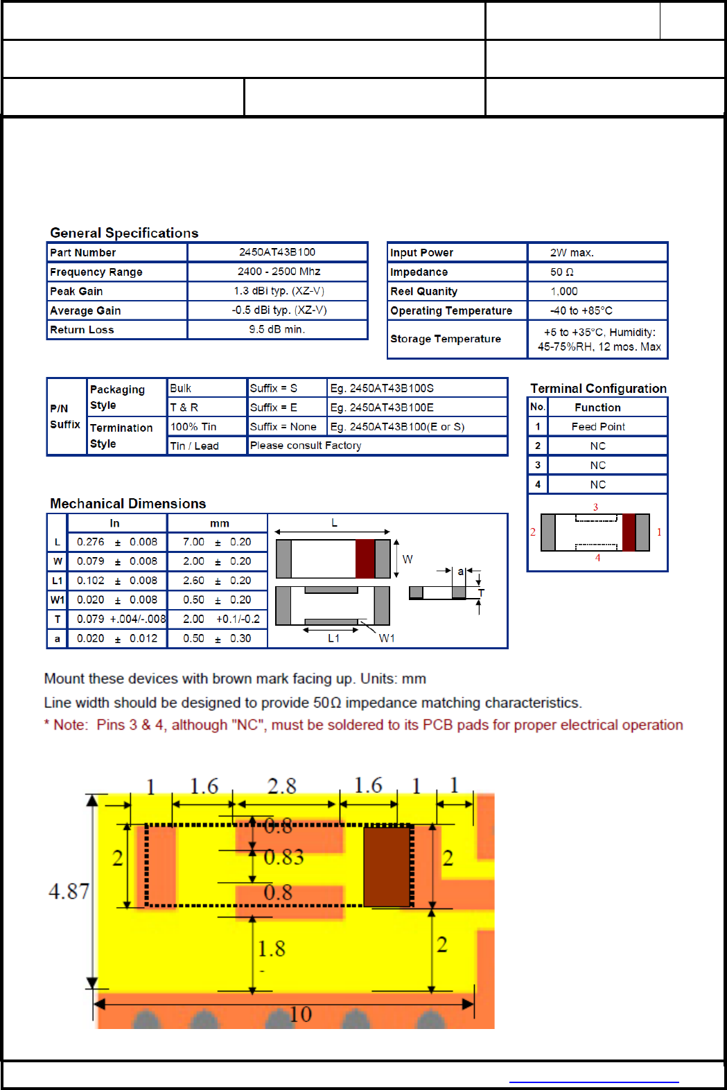
1.1.2. Answer 11 item 1b, c:
Only chip antennas listed below can be used:
Johanson partnumber 2450AT43B100
CLASSIFICATION
FCC ID T7V1315
OEM antenna instructions
No.
Instructions_Antenna
REV.
1.0
SUBJECT
Manual according KDB996369 question 11
for host manufactures how to design antennas
PAGE
4 of 4
DATE
12.05.2015
PANASONIC INDUSTRIAL DEVICES EUROPE GMBH
www.pideu.panasonic.de
1.1.3. Answer 11 item 1d:
Above data for PCB layout can be requested in original Cad format by writing an email to
wireless@eu.panasonic.com
1.1.4. Answer 11 item 2:
If using an chip antenna R18, C9, L2 has to be mounted. For C9 the manufacturer has to be
Murata 0402/COG/2.2pF/50V. For L2 the manufacturer has to be Murata with part number
LQG15HN3N6S02.
1.1.5. Answer 11 item 3:
The impedance S12 of the antenna including the trace shall be measured with a network
analyser.
Answer 11 Item 4:
In the production the output power of the radiated emissions shall be measured with a
spectrum analyser.
2. HISTORY FOR THIS DOCUMENT
Revision
Version
Date
Datum
Modification / Remarks
Änderungen / Bemerkungen
1.0
12.05.2015
Puplished Version for FCC Website