Panasonic of North America PT-VW350 LCD PROJECTOR User Manual PT VW350 Manual Part 1 2
Panasonic Corporation of North America LCD PROJECTOR PT VW350 Manual Part 1 2
Contents
- 1. PT-VW350_Manual Part 1-1
- 2. PT-VW350_Manual Part 1-2
- 3. PT-VW350_Manual Part 2
- 4. PT-VW350_Manual Part 3
PT-VW350_Manual Part 1-2
Attention
fDo not block the ventilation ports (intake and exhaust) of the projector.
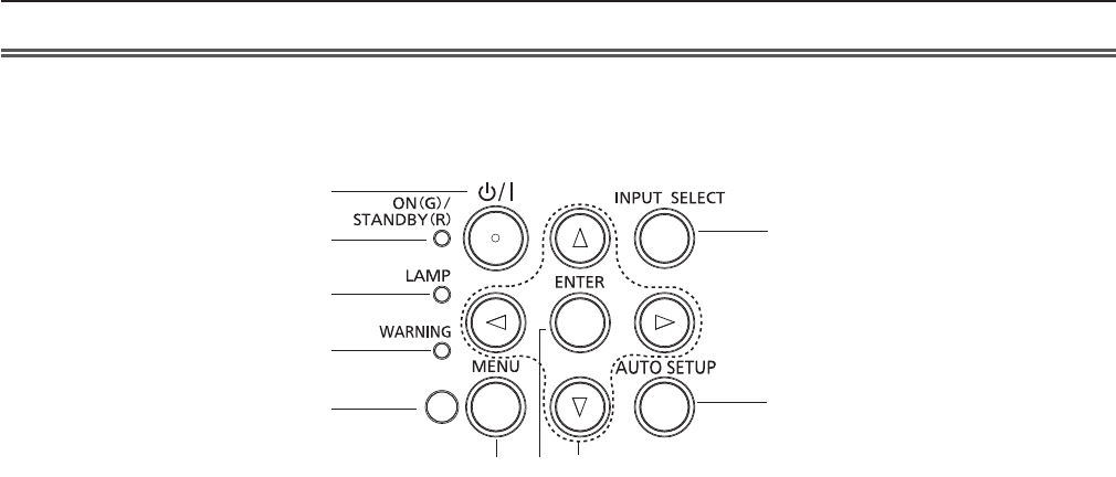
rControl panel and Indicators
1 Power <v/b> button
Turns the projector on/off.
(v standby / b power on)
2 Power indicator <ON(G)/STANDBY(R)>
Displays the status of the power.
3 Lamp indicator <LAMP>
Displays the status of the lamp.
4 Warning indicator <WARNING>
Indicates the abnormal conditions of the projector.
5 Ambient Luminance sensor
Detects room's light and select proper image
quality.
6 <MENU> button
Displays the menu screen. (x page 47)
7 <ENTER> button
Determines and executes an item in the menu
screen.
8 asqw buttons
Navigate the MENU screen.
Adjust the volume level (qw).
9 <INPUT SELECT> button
Select the input signal for projection.
(x page 40)
10 <AUTO SETUP> button
Executes the auto setup function.
1
2
3
4
5
678
9
10
ENGLISH - 21
Chapter 1 Preparation - About your projector
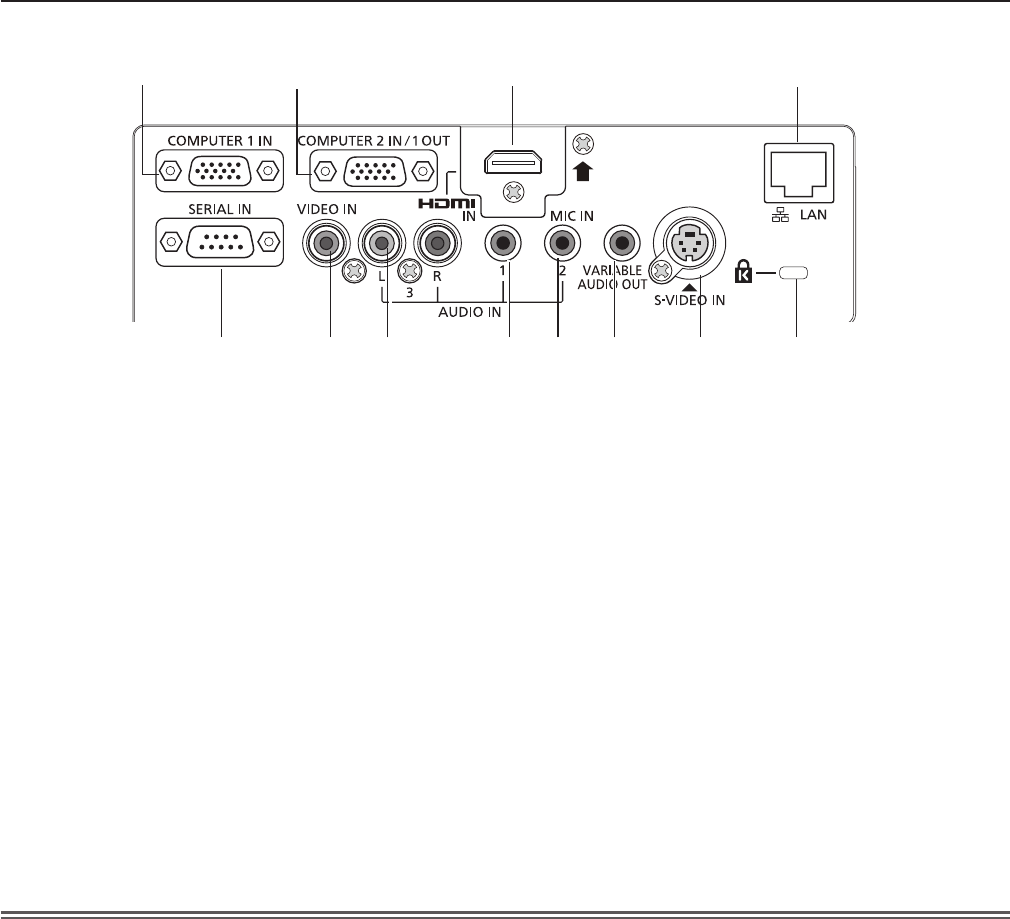
rConnecting terminals
Attention
fWhen a LAN cable is directly connected to the projector, the network connection must be made indoors.
1 <COMPUTER 1 IN> terminal
This is the terminal to input RGB or YCBCR/YPBPR
signals.
2 <COMPUTER 2 IN/ 1 OUT> terminal
This is the terminal to input RGB signals.
Or output the RGB or YCBCR/YPBPR signals to
external monitor.
3 <HDMI IN> terminal
This is the terminal to input HDMI signals.
4 <LAN> terminal
This is the LAN terminal to connect to the network.
5 <SERIAL IN> terminal
This is the RS-232C compatible terminal to
externally control the projector by connecting a
computer.
6 <VIDEO IN> terminal
This is the terminal to input video signals.
7 <AUDIO IN 3 (L/R)> terminal
This is the terminal to input audio signals.
Left input (L) and right input (R) are provided for
the <AUDIO IN 3> terminal.
8 <AUDIO IN 1> terminal
This is the terminal to input audio signals.
9 <AUDIO IN 2 (MIC IN)> terminal
This is the terminal to input audio signals. Or
connect the MIC to this terminal.
10 <VARIABLE AUDIO OUT> terminal
This is the terminal to output the input audio signal
to the projector.
11 <S-VIDEO IN> terminal
This is the terminal to input s-video signals.
12 Security slot
Attach the commercial shackle lock, manufactured
by Kensington, to protect your projector.
Compatible with the Kensington MicroSaver
Security System.
1234
5 6 78910 11 12
22 - ENGLISH
Chapter 1 Preparation - About your projector
Preparing the remote control
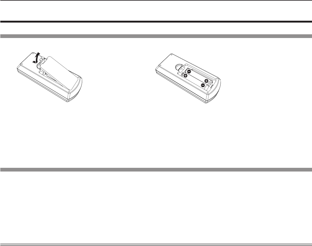
Inserting and removing batteries
(i)
(ii)
(i)
(ii)
1) Open the cover. (Fig. 1)
2) Insert batteries and close the cover. (Insert the m side first.) (Fig. 2)
fWhen removing the batteries, perform the steps in reverse order.
When using the system with multiple projectors
When you use the system with multiple projectors, you can operate all the projectors simultaneously or each projector
individually by using single remote control, if a unique ID number is assigned to each projector.
When you want to set the ID number, at rst you need to complete the Initial setting, and then after setting the ID number of
the projector, set the ID number on the remote control. About Initial setting, please refer to “When the initial setting screen is
displayed” (x page 36).
The factory default ID number of the unit (the projector and the remote control) is set to [ALL], you can control with this setting.
If necessary, please set the ID number to the remote control and the projector. About how to set the ID number of the remote
control, please refer to “Setting the ID number of the remote control” (x page 45).
Note
fSet the ID number of the projector from the [PROJECTOR SETUP] menu → [PROJECTOR ID]. (x page 69)
Fig. 2
Fig. 1
ENGLISH - 23
Chapter 1 Preparation - Preparing the remote control
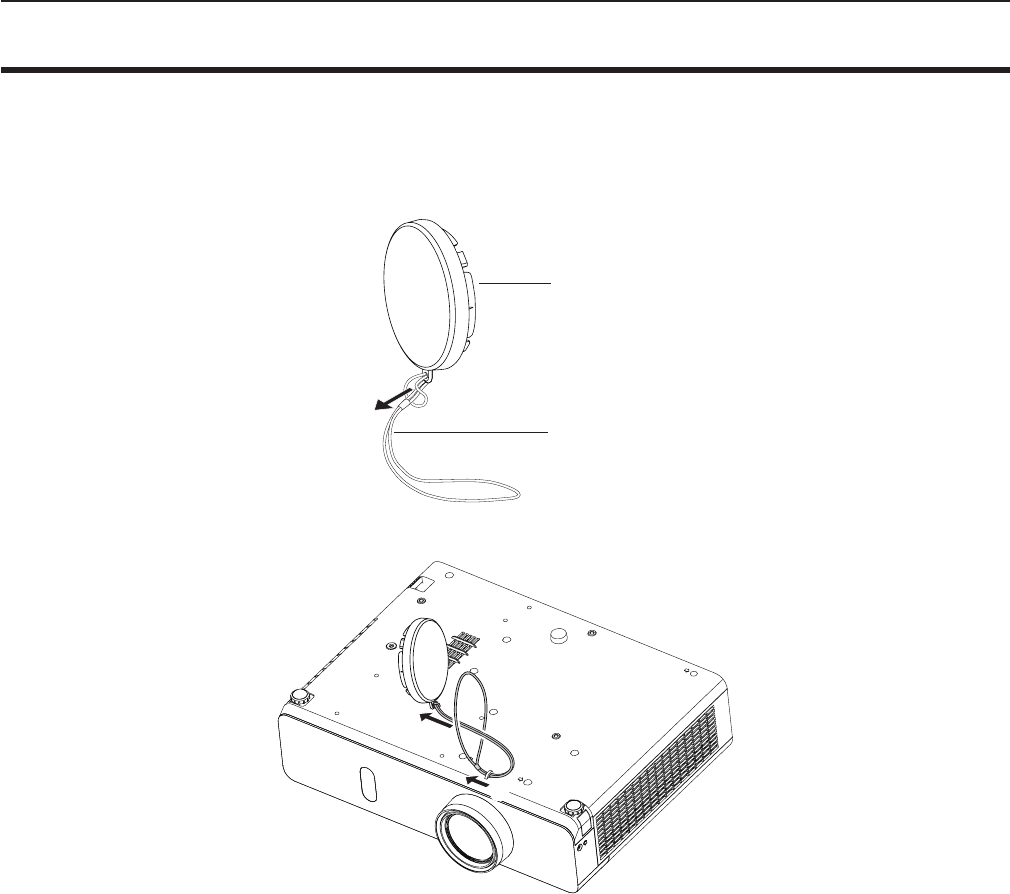
Attaching the Lens Cap
When moving this projector or while not using it over an extended period of time, attach the lens cap.
To prevent loss for the lens cap, please according to the following procedures, attach the lens cap with the string of
accessories.
1) Thread the thinner end of the string through the hole on the lens cap.
Lens cap
String
2) Thread the other end of the string through the hole on the bottom of the projector.
(ii)
(i)
24 - ENGLISH
Chapter 1 Preparation - Attaching the Lens Cap

Chapter 2 Getting Started
This chapter describes things you need to do before using the projector such as the setup and
connections.
ENGLISH - 25
Setting up
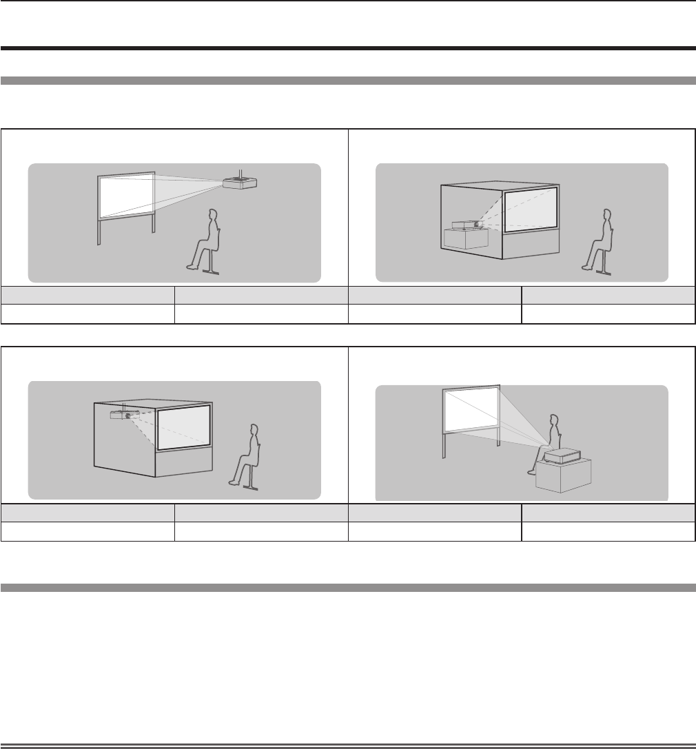
Installation mode
There are four ways to set up the projector. Set the [PROJECTOR SETUP] menu → [PROJECTION METHOD] (x page 70)
depending on the installation location.
Mounting on the ceiling and projecting forward Setting on a desk/oor and projecting from rear
(Using the translucent screen)
Menu item Method Menu item Method
[PROJECTION METHOD] [FRONT/CEILING] [PROJECTION METHOD] [REAR/DESK]
Mounting on the ceiling and projecting from rear
(Using the translucent screen)
Setting on a desk/oor and projecting forward
Menu item Method Menu item Method
[PROJECTION METHOD] [REAR/CEILING] [PROJECTION METHOD] [FRONT/DESK]
Parts for ceiling mount (optional)
This requires an optional ceiling mount bracket. Be sure to use the Projector Mount Bracket together with the ceiling mount
bracket for high ceilings or low ceilings.
Model No.:
① ET-PKL100H (for high ceilings), ET-PKV400B (Projector Mount Bracket)
② ET-PKL100S (for low ceilings), ET-PKV400B (Projector Mount Bracket)
fUse only the ceiling mount brackets specied for this projector.
fRefer to the Installation Instructions for the ceiling mount bracket when you install the bracket and the projector.
Attention
fTo ensure projector performance and security, installation of the ceiling mount bracket must be carried by your dealer or a
qualied technician.
26 - ENGLISH
Chapter 2 Getting Started - Setting up
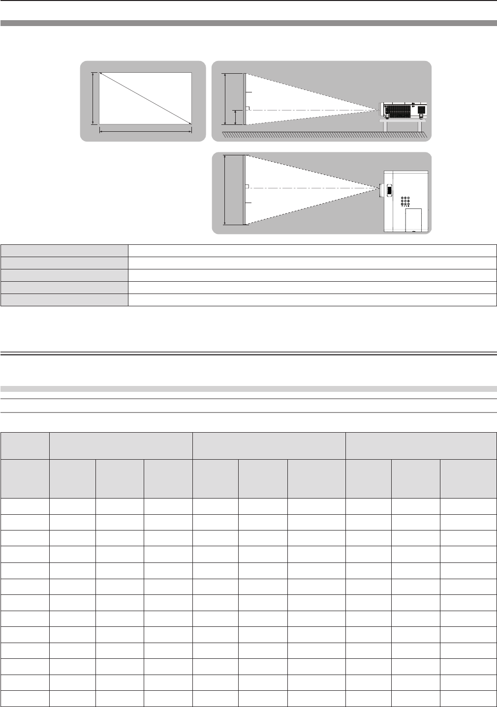
Screen size and throw distance
Refer to the screen size and projection distances to install the projector. Image size and image position can be adjusted in
accordance with the screen size and screen position.
Projected image
SH
SW
SD
SH
Screen
L (LW/LT)
Screen
L (LW/LT)
SW
H
L (LW/LT) *1Projection distance (m)
SH Image height (m)
SW Image width (m)
HDistance from the center of lens to the image lower end (m)
SD Projected image size (m)
*1 LW : Minimum distance
LT : Maximum distance
Attention
fBefore installing, please read “Precautions for Use” (x page 14).
Projection distance
For PT-VW350
All measurements below are approximate and may differ slightly from the actual measurements. (Unit: m)
Projection
size For 4:3 aspect ratio For 16:9 aspect ratio For 16:10 aspect ratio
Screen
diagonal
(SD)
Minimum
distance
(LW)
Maximum
distance
(LT)
Height
position
(H)
Minimum
distance
(LW)
Maximum
distance
(LT)
Height
position (H)
Minimum
distance
(LW)
Maximum
distance
(LT)
Height
position (H)
0.76 (30") 0.83 1.37 0.009 0.76 1.24 -0.012 0.73 1.21 0.008
1.02 (40") 1.13 1.85 0.012 1.02 1.68 -0.017 0.99 1.63 0.011
1.27 (50") 1.41 2.31 0.015 1.28 2.09 -0.021 1.25 2.04 0.013
1.52 (60") 1.70 2.77 0.018 1.54 2.51 -0.025 1.50 2.44 0.016
1.78 (70") 1.99 3.25 0.021 1.81 2.95 -0.029 1.76 2.87 0.019
2.03 (80") 2.28 3.71 0.024 2.07 3.37 -0.033 2.01 3.27 0.022
2.29 (90") 2.57 4.19 0.027 2.33 3.80 -0.037 2.27 3.70 0.024
2.54 (100") 2.86 4.65 0.030 2.59 4.22 -0.041 2.52 4.10 0.027
3.05 (120") 3.44 5.59 0.037 3.12 5.07 -0.050 3.03 4.93 0.032
3.81 (150") 4.30 6.99 0.046 3.90 6.34 -0.062 3.80 6.17 0.040
5.08 (200") 5.74 9.33 0.061 5.21 8.47 -0.083 5.07 8.24 0.054
6.35 (250") 7.19 11.67 0.076 6.52 10.59 -0.104 6.34 10.30 0.067
7.62 (300") 8.63 14.01 0.091 7.82 12.72 -0.124 7.62 12.37 0.081
ENGLISH - 27
Chapter 2 Getting Started - Setting up
For PT-VX420
All measurements below are approximate and may differ slightly from the actual measurements. (Unit: m)
Projection size For 4:3 aspect ratio For 16:9 aspect ratio
Screen diagonal (SD)
Minimum
distance
(LW)
Maximum
distance
(LT)
Height position (H)
Minimum
distance
(LW)
Maximum
distance
(LT)
Height position (H)
0.76 (30") 0.69 1.14 0.046 0.75 1.24 -0.012
1.02 (40") 0.94 1.54 0.061 1.02 1.68 -0.017
1.27 (50") 1.17 1.92 0.076 1.28 2.09 -0.021
1.52 (60") 1.41 2.30 0.091 1.54 2.51 -0.025
1.78 (70") 1.65 2.70 0.107 1.81 2.94 -0.029
2.03 (80") 1.89 3.08 0.122 2.06 3.36 -0.033
2.29 (90") 2.14 3.48 0.137 2.33 3.80 -0.037
2.54 (100") 2.37 3.87 0.152 2.59 4.21 -0.031
3.05 (120") 2.86 4.65 0.183 3.11 5.07 -0.050
3.81 (150") 3.58 5.81 0.229 3.90 6.33 -0.062
5.08 (200") 4.78 7.76 0.305 5.21 8.45 -0.083
6.35 (250") 5.98 9.70 0.381 6.52 10.57 -0.104
7.62 (300") 7.18 11.65 0.457 7.82 12.70 -0.124
Projection distance formulas
Any other projection distance can be obtained according to the screen dimensions (m) by using the following calculations.
The calculated distance may contain a certain error.
If you want to calculate the projection distance with projected image size SD (unit: inch) by substituting, please assign 0.0254
times to the SD value.
For PT-VW350
For 4:3 aspect ratio For 16:9 aspect ratio For 16:10 aspect ratio
Screen height (SH) = 0.6 × SD(m) = 0.490 × SD(m) = 0.530 × SD(m)
Screen width (SW) = 0.8 × SD(m) = 0.872 × SD(m) = 0.848 × SD(m)
Minimum distance (LW) = 1.1363 × SD(m) - 0.0290 = 1.0316 × SD(m) - 0.0290 = 1.0037 × SD(m) - 0.0290
Maximum distance (LT) = 1.8422 × SD(m) - 0.0292 = 1.6725 × SD(m) - 0.0292 = 1.6273 × SD(m) - 0.0292
For PT-VX420
For 4:3 aspect ratio For 16:9 aspect ratio
Screen height (SH) = 0.6 × SD(m) = 0.490 × SD(m)
Screen width (SW) = 0.8 × SD(m) = 0.872 × SD(m)
Minimum distance (LW) = 0.9461 × SD(m) - 0.0295 = 1.0307 × SD(m) - 0.0295
Maximum distance (LT) = 1.5324 × SD(m) - 0.0272 = 1.6696 × SD(m) - 0.0272
28 - ENGLISH
Chapter 2 Getting Started - Setting up
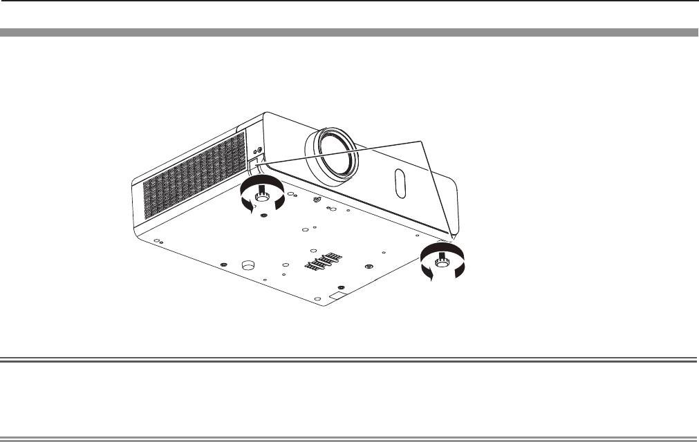
Adjusting adjustable feet
Lift the front of the projector and press the feet lock latches on both side of the projector.
Release the feet lock latches to lock the adjustable feet and rotate the adjustable feet to a proper height and tilt.
Extend the adjustable feet by rotating in the direction shown in the gure and retract by rotating in the opposite direction.
Feet lock latches
Attention
fHeated air comes out of the air exhaust port while the lamp is lit. Do not touch the air exhaust port directly when you adjust
the adjustable feet.
fIf keystone distortion occurs on the projected image, perform [KEYSTONE] from the [POSITION] menu. (x page 56)
Note
fScrew up the adjustable feet, and an audible click will be heard as the limit.
Adjustable range
Adjustable feet : 43 mm (1-11/16")
ENGLISH - 29
Chapter 2 Getting Started - Setting up
Connecting
Before connecting
fBefore connecting, carefully read the operating instructions for the external device to be connected.
fTurn off the power switch of the devices before connecting cables.
fTake note of the following points before connecting the cables. Failure to do so may result in malfunctions.
- When connecting a cable to a device connected to the projector or the projector itself, touch any nearby metallic objects to
eliminate static electricity from your body before performing work.
- Do not use unnecessarily long cables to connect to a device connected to the projector or to the projector body. The longer
the cable, the more it is susceptible to noise. Since using a cable while it is wound makes it act like an antenna, it is more
susceptible to noise.
- When connecting cables, connect GND rst, then insert the connecting terminal of the connecting device in a straight
manner.
fIf any connection cable is not supplied with the device, or if no optional cable is available for connection of the device,
prepare a necessary system connection cable to suit the device.
fVideo signals containing too much jitter may cause the images on the screen to randomly wobble or wafture.
In this case, a time base corrector (TBC) must be connected.
fThe projector accepts VIDEO signals, S-VIDEO signals, YCBCR/YPBPR signals and analog RGB signals (synchronous signals
are TTL level), and digital signal.
fSome computer models or graphics cards are not compatible with the projector.
fWhen using long cables to connect with each of equipment to the projector, there is a possibility that the image will not be
output correctly unless a compensator is used.
fFor details on what video signals the projector supports, see “List of compatible signals”. (x page 112)
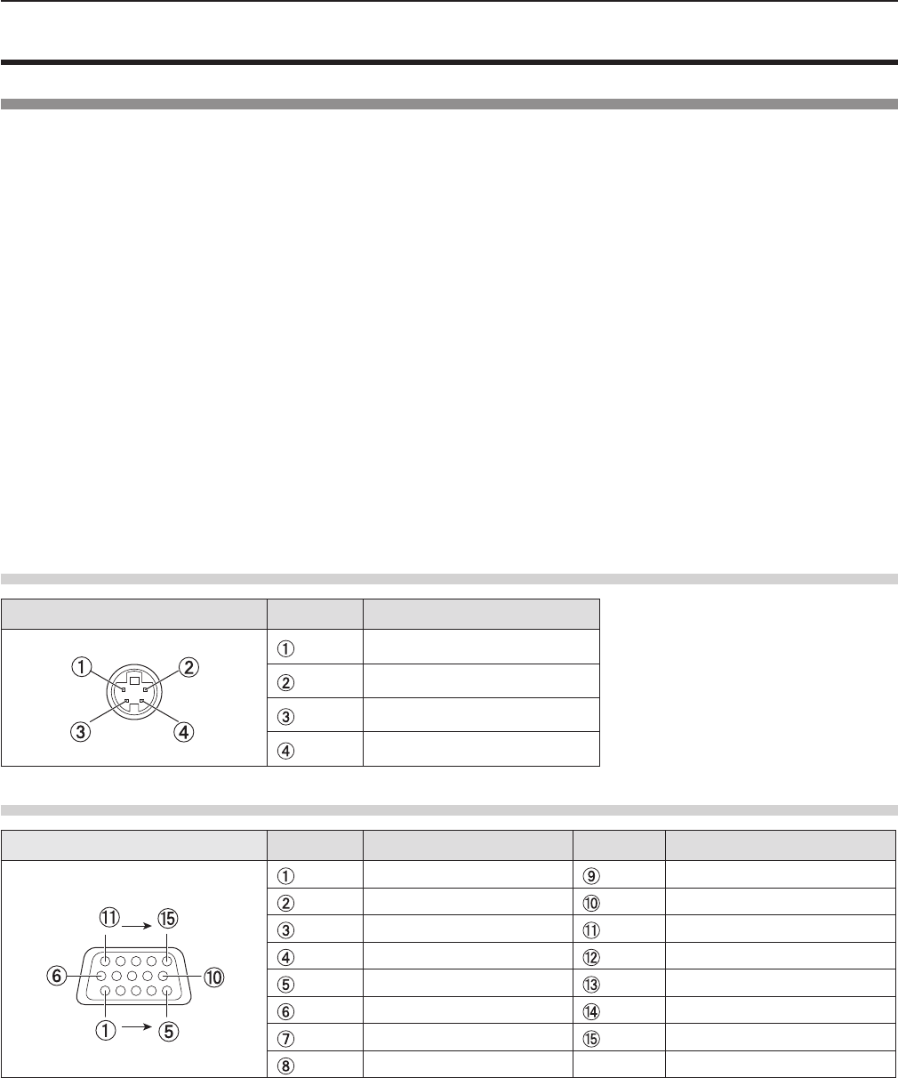
<S-VIDEO IN> terminal pin assignments and signal names
Outside view Pin No. Signal names
GND (luminance signal)
GND (color signal)
Luminance signal
Color signal
<COMPUTER 1 IN> terminal pin assignments and signal names
Outside view Pin No. Signal names Pin No. Signal names
R/PR+ 5 V
G/Y GND
B/PBGND
—DDC data
GND HD/SYNC
GND VD
GND DDC clock
GND
30 - ENGLISH
Chapter 2 Getting Started - Connecting
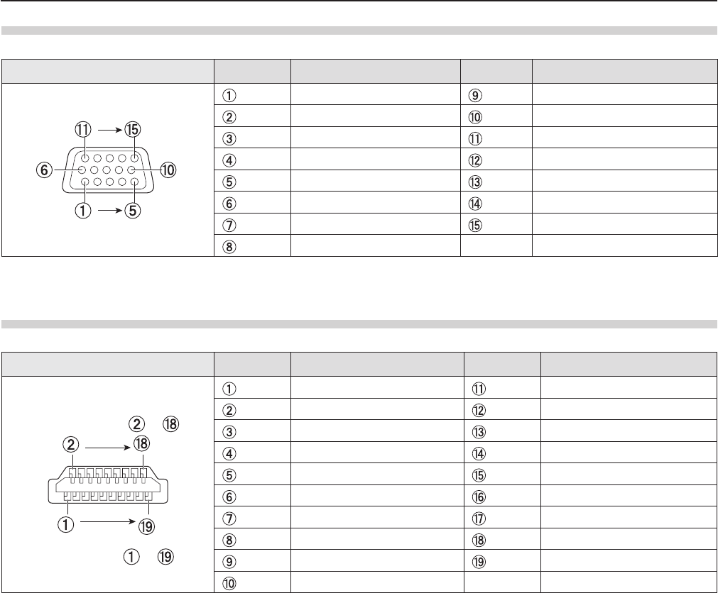
<COMPUTER 2 IN/1 OUT> terminal pin assignments and signal names
Outside view Pin No. Signal names Pin No. Signal names
R/PR
*1 +5 V
G/Y*1 GND
B/PB
*1 —
—DDC data
GND HD/SYNC
GND VD
GND DDC clock
GND
*1: It is only for RGB signals when the terminal is used as the input terminal.
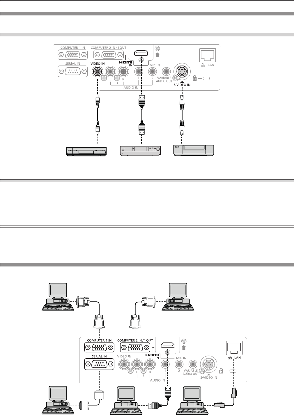
<HDMI IN> terminal pin assignments and signal names
Outside view Pin No. Signal names Pin No. Signal names
T.M.D.S data 2+ T.M.D.S clock shield
T.M.D.S data 2 shield T.M.D.S clock
-
T.M.D.S data 2
-
CEC
T.M.D.S data 1+ —
T.M.D.S data 1 shield SCL
T.M.D.S data 1
-
SDA
T.M.D.S data 0+ DDC/CEC GND
T.M.D.S data 0 shield +5 V
T.M.D.S data 0
-
Hot plug detection
T.M.D.S clock +
Odd-numbered
pins to
Even-numbered
pins to
ENGLISH - 31
Chapter 2 Getting Started - Connecting
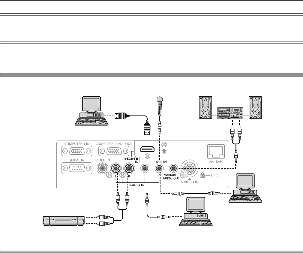
Connecting example : AV equipment
For <HDMI IN>/<VIDEO IN>/<S-VIDEO IN> terminals
Attention
fAlways use one of the following when connecting a VCR.
- A VCR with built-in time base corrector (TBC).
- A time base corrector (TBC) between the projector and the VCR.
fIf nonstandard burst signals are connected, the image may be distorted. In such case, connect the time base corrector
(TBC) between the projector and the external devices.
Note
fFor an HDMI cable, use an HDMI High Speed cable that conforms to HDMI standards. If a cable that does not conform to
HDMI standards is used, images may be interrupted or may not be displayed.
fThis projector does not support the Viera link (HDMI).
Connecting example : Computers
Video deck (TBC built-in) Blu-ray disk player
with HDMI terminal
DVD player
Control computer
Computer
Control computer
Computer Computer
32 - ENGLISH
Chapter 2 Getting Started - Connecting
Attention
fWhen connecting the projector to a computer or an external device, use the power cord supplied with each device and
commercially available shielded cables.
Note
fIf you operate the projector using the computer with the resume feature (last memory), you may have to reset the resume
feature to operate the projector.
Connecting example : Audio
Note
fIf the [AUDIO IN SELECT] settings are incorrect, the projector may have malfunctions such as the absence of audio.
(x page 74)
fWhen the <VARIABLE AUDIO OUT> terminal is connected with cable, the sound will not be output from the built-in speaker.
Computer
Computer
MIC
Computer Audio equipment
AV equipment
ENGLISH - 33
Chapter 2 Getting Started - Connecting

Chapter 3 Basic Operations
This chapter describes basic operations to start with.
34 - ENGLISH
Powering on/off
Connecting the power cord
Make sure that the supplied power cord is securely xed to the projector body to prevent it from being removed
easily.
For details of power cord handling, refer to “Read this rst!” (x page 2).
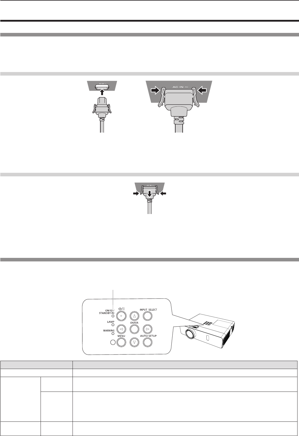
Attaching
1) Check the shapes of the <AC IN> terminal on the back of the projector body and the power cord
connector and insert the plug completely in the correct direction (until you hear the side tabs click in
place).
Removing
1) Confirm that the projector is in standby mode, and remove the power plug from the outlet.
2) Remove the power cord connector from the <AC IN> terminal of the projector body while pressing the
side tabs.
Power indicator
The power indicator <ON(G)/STANDBY(R)> informs you the status of the power. Conrm the status of the power indicator
<ON(G)/STANDBY(R)> before operating the projector.
Indicator status Status
Off The power cord is unplugged.
Red
Lit
The power is switched off (in standby mode). The [PROJECTOR SETUP] menu x
[ECO
MANAGEMENT] x
[STANDBY MODE] is set to [ECO].
Blinking
The power is switched off (in standby mode). The [PROJECTOR SETUP] menu
x
[ECO
MANAGEMENT] x
[STANDBY MODE] is set to [NETWORK].*1
The power is switched off (in standby mode). The
[PROJECTOR SETUP] menu
x
[ECO
MANAGEMENT] x
[STANDBY MODE] is set to [NORMAL].*2
Orange Lit The projector is cooling down. The power is switched off after a while. (Changes to the
standby mode.)
Power indicator <ON(G)/STANDBY(R)>
ENGLISH - 35
Chapter 3 Basic Operations - Powering on/off
Indicator status Status
Green
Lit Projecting.
Blinking
The power is on and the lamp is not working. The
[PROJECTOR SETUP] menu
x
[ECO
MANAGEMENT] x
[POWER MANAGEMENT] is set to [READY].*3
The lamp starts work. The projector will project image after a while.*4
*1: The indicator will light as the following order:
2.75 seconds (light) → 0.25 seconds (off) → 0.75 seconds (light) → 0.25 seconds (off)
*2: The indicator will light as the following order:
2.75 seconds (light) → 0.25 seconds (off)
*3: The indicator will light as the following order:
2.0 seconds (light) → 2.0 seconds (off)
*4: The indicator will light as the following order:
0.5 seconds (light) → 0.5 seconds (off)
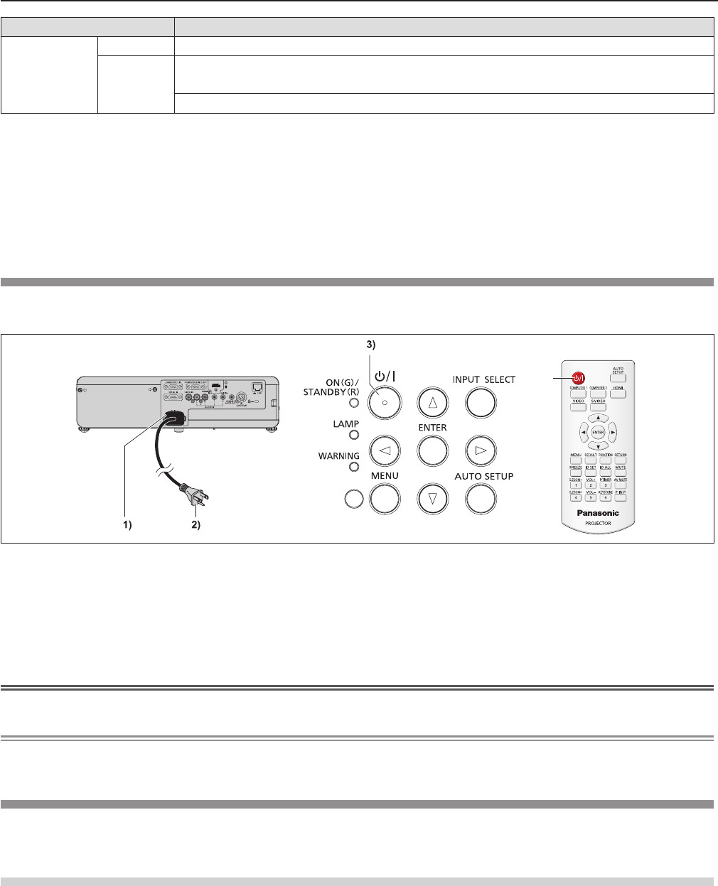
1) Connect the power cord to the projector body.
2) Connect the power plug to an outlet.
fThe power indicator <ON(G)/STANDBY(R)> lights or blinks, and the projector will enter the standby mode.
3) Press the power <v/b> button on the control panel or on the remote control.
fThe power indicator <ON(G)/STANDBY(R)> lights in green and the image is soon projected on the screen.
Attention
fBe sure to remove the lens cap before starting projection.
Note
fIf the [PROJECTOR SETUP] menu → [ECO MANAGEMENT] → [STANDBY MODE] is set to [ECO], it may take approx. 10
seconds longer before the projector starts projecting after the power is turned on, compared with when [NORMAL] is set.
When the initial setting screen is displayed
When the projector is switched on for the rst time after purchase as well as when [INITIALIZE ALL] in the [PROJECTOR
SETUP] menu is executed, then the initial setting screen is displayed. Set them in accordance with circumstances.
In other occasions, you can change the settings by menu operations.
Initial setting (display language)
Select the language to show on the screen.
After completed the initial setting, you can change the display language from the [LANGUAGE] menu.
Powering On the Projector
Before switching on the projector, make sure all the other devices are correctly connected (x page 32) and remove the lens
cap.
3)
36 - ENGLISH
Chapter 3 Basic Operations - Powering on/off
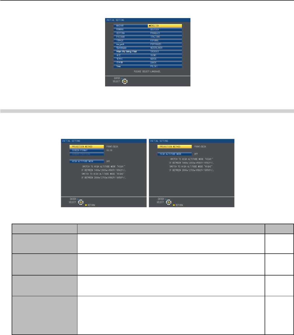
1) Press asqw to select the display language.
2) Press the <ENTER> button to proceed to the initial setting.
Initial setting (installation setting)
Set each item.
1) Press as to select an item.
Item Description Page
[PROJECTION METHOD]
Set [PROJECTION METHOD] depending on the installation mode.
After completed the initial setting, you can change the setting from the [PRO-
JECTOR SETUP] menu → [PROJECTION METHOD].
70
[SCREEN FORMAT]*1
Set the screen format (aspect ratio) and display position of the image. After
completed the initial setting, you can change the settings of each item from the
[DISPLAY OPTION] menu → [SCREEN SETTING].
64
[SCREEN POSITION]*1
Set the display position of the image. After completed the initial setting, you
can change the settings of each item from the [DISPLAY OPTION] menu →
[SCREEN SETTING].
64
[HIGH ALTITUDE MODE]
Change the setting when the projector is used at high altitude.
Set it to [OFF] when using the projector at altitude lower than 1 400 m (4 593'),
set it to [HIGH1] when using the projector at altitude between 1 400 m (4 593’)
and 2 000 m (6 562') above sea level, and set it to [HIGH2] when using the
projector at altitude between 2 000 m (6 562’) and 2 700 m (8 858') above sea
level.
70
*1 Only for PT-VW350.
2) Press qw to switch the setting.
3) Press the <ENTER> button to perform next initial setting.
PT-VX420
PT-VW350
ENGLISH - 37
Chapter 3 Basic Operations - Powering on/off
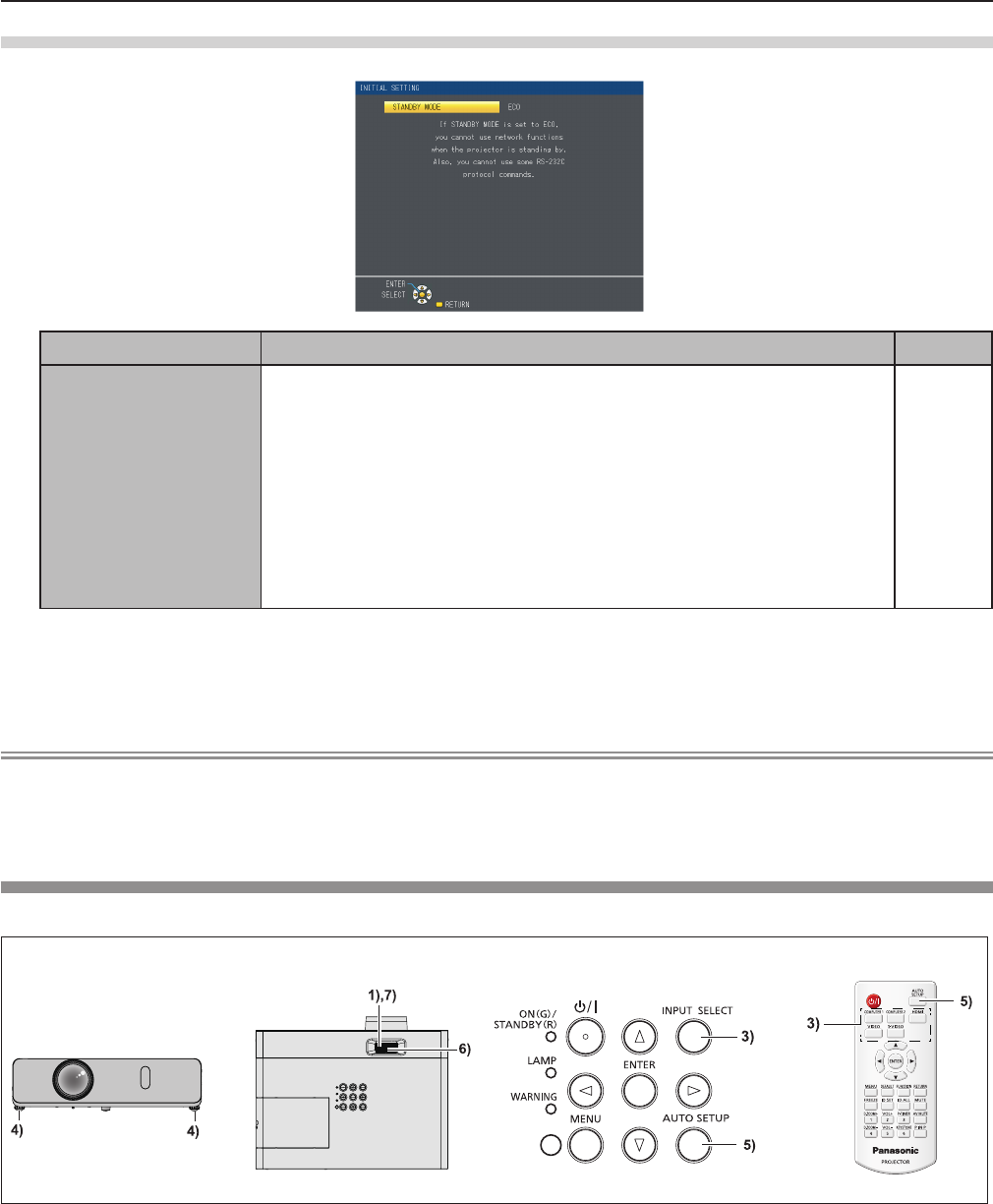
Initial setting (standby mode)
Item Description Page
[STANDBY MODE]
Set the operation mode during standby.
f The default setting is [ECO] that keeps power consumption low during
standby.
f Set to [NORMAL] to use the network function or the serial communication
function during standby.
f Set to [NETWORK] to reduce power consumption during standby, and to
operate the projector via the wired LAN or the serial communication function
by using the Wake on LAN function.
After completed the initial setting, you can change the setting from the [PRO-
JECTOR SETUP] menu → [ECO MANAGEMENT] → [STANDBY MODE].
72
1) Press qw to switch the setting.
2) Press the <ENTER> button.
fConrm the setting value and complete the initial setting.
Note
fIf you press the <RETURN> button while the initial setting screen is displayed, you can go back to the previous screen.
fThe above initial setting screen is the one displayed when the projector is switched on for the rst time after purchase.
When [PROJECTOR SETUP] menu → [INITIALIZE ALL] is executed, the setting of [STANDBY MODE] before execution is
displayed.
Making adjustments and selections
It is recommended that images are projected continuously for at least 30 minutes before the focus is adjusted.
1) Adjust the focus of the image roughly. (x page 40)
2) Change the settings of the [PROJECTOR SETUP] menu → [PROJECTION METHOD] depending on the
installation mode. (x page 70)
fRefer to “Navigating through the menu” (x page 47) for the operation of the menu screen.
3) Press the <INPUT SELECT> button on the control panel or the input selection (<COMPUTER 1>,
<COMPUTER 2>, <HDMI>, <VIDEO>, <S-VIDEO>) buttons on the remote control to select the input
signal.
4) Adjust the front, back and sideway tilt of the projector with the adjustable feet. (x page 29)
5) If the input signal is an analog RGB signal, press the <AUTO SETUP> button.
38 - ENGLISH
Chapter 3 Basic Operations - Powering on/off
6) Adjust the size of the image to match the screen with the zoom ring.
7) Adjust the focus with the focus ring.
Note
fWhen the projector is switched on for the rst time after purchase as well as when the [PROJECTOR SETUP] menu →
[INITIALIZE ALL] is executed, the initial setting screen is displayed after projection starts.
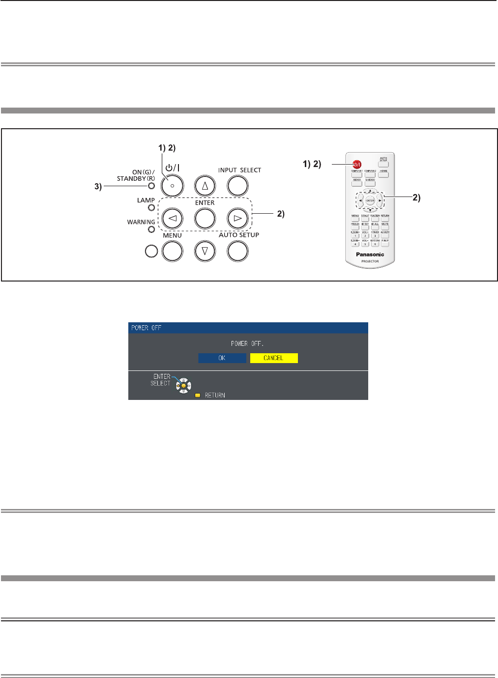
Powering Off the Projector
1) Press the power <v/b> button on the control panel or on the remote control.
fThe following message appears.
2) Press qw to select [OK], and press the <ENTER> button.
(Or press the power <v/b> button on the control panel or on the remote control again.)
fProjection of the image will stop, and the power indicator <ON(G)/STANDBY(R)> lights in orange. (The fans keep
running.)
3) Wait until the power indicator <ON(G)/STANDBY(R)> lights or blinks in red.
fThe projector enters standby mode when the power indicator <ON(G)/STANDBY(R)> lights or blinks in red.
Note
fWhile the power indicator <ON(G)/STANDBY(R)> is lighting in orange, the lamp is being cooled down and the projector
cannot be turned on. Wait until the power indicator <ON(G)/STANDBY(R)> starts lighting or blinking in red to turn on the
projector again.
fWhen packing the projector for transportation and storage, please make sure that each indicator is off.
Direct Power Off function
You can disconnect the power cord from the wall outlet or turn off the power breaker switch even during projection.
Attention
fDo not disconnect the power cord from the wall outlet or turn off the power breaker switch in a short time (about 1 minute)
after the lamp is lit. Doing so may cause the lamp fail to light while you powering on the projector next time, or result in
premature deterioration of the lamp.
Note
fWhen using the Direct Power Off function, you cannot restart the projector immediately after disconnecting the power cord
from the wall outlet or turning off the power breaker switch. The lamp remains high temperature and needs to cool down, so
it sometimes takes a longer time than usual for the lamp to light up again.
ENGLISH - 39
Chapter 3 Basic Operations - Powering on/off
Projecting
Check the connections of the peripheral devices (x page 30) and connection of the power cord (x page 34) and switch
on the power (x page 36) to start the projector. Select the image and adjust the state of the image.
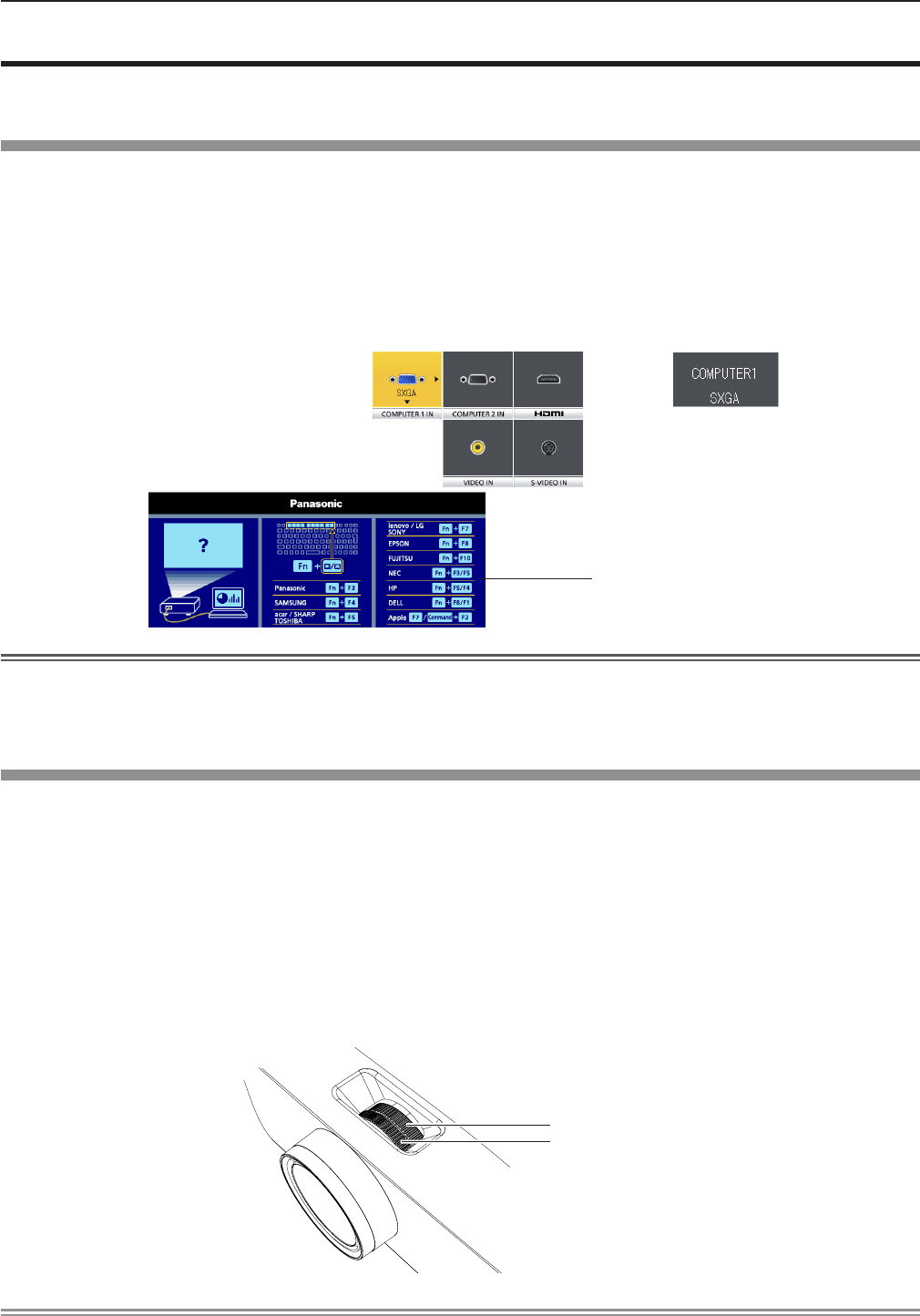
Selecting the input signal
Select an input signal.
1) Press the <COMPUTER 1>, <COMPUTER 2>, <HDMI>, <VIDEO> or <S-VIDEO> button on the remote control or
<INPUT SELECT> button on the control panel.
fThe image of the signal being input in the selected terminal is projected.
fYou can check the input source through [DETAILED] / [SIMPLE] under the [DISPLAY OPTION] → [ON-SCREEN
DISPLAY] → [INPUT GUIDE] menu.
fYou can also select the input source by pressing asqw on the [DETAILED] screen.
Attention
fImages may not be projected properly depending on the connected device and DVD, video tape, etc. to be played. Set the
[PICTURE] menu → [RGB/YCBCR] or [RGB/YPBPR] (x page 55).
fCheck the aspect ratio of the screen and the image and select the optimum aspect ratio under the [POSITION] menu
(x page 59).
How to adjust the state of the image
If the projected image or the position is not correct when the positioning of the projector and the screen is correctly installed, adjust the focus
and zoom.
1) Adjust the projection angle.
fInstall the projector on a at surface and parallel to the screen so that the projected screen is rectangular.
fIf the screen is tilted downward, extend the adjustable feet and adjust the projection screen so that the projected screen
is rectangular.
fFor details, see “Adjusting adjustable feet” (x page 29)
.
2) Adjust the zoom and the focus.
fRotate the zoom ring to zoom in and out the image.
fRotate the focus ring to adjust the focus of the projected image.
Note
fIt is recommended that the images are projected continuously for at least 30 minutes before the focus is adjusted.
fIf you adjust the focus, you may need to adjust the size of the image by turning the zoom ring again.
fIf keystone distortion occurs, see the [POSITION] menu → [KEYSTONE] (x page 56).
[DETAILED] input guide [SIMPLE] input guide
Focus ring
Zoom ring
If there is no signal input
([COMPUTER1], [COMPUTER2] or
[HDMI]), this screen will be displayed.
Check the output settings of your
computer.
40 - ENGLISH
Chapter 3 Basic Operations - Projecting