Panasonic of North America PT-VW350 LCD PROJECTOR User Manual PT VW350 Manual Part 3
Panasonic Corporation of North America LCD PROJECTOR PT VW350 Manual Part 3
Contents
- 1. PT-VW350_Manual Part 1-1
- 2. PT-VW350_Manual Part 1-2
- 3. PT-VW350_Manual Part 2
- 4. PT-VW350_Manual Part 3
PT-VW350_Manual Part 3
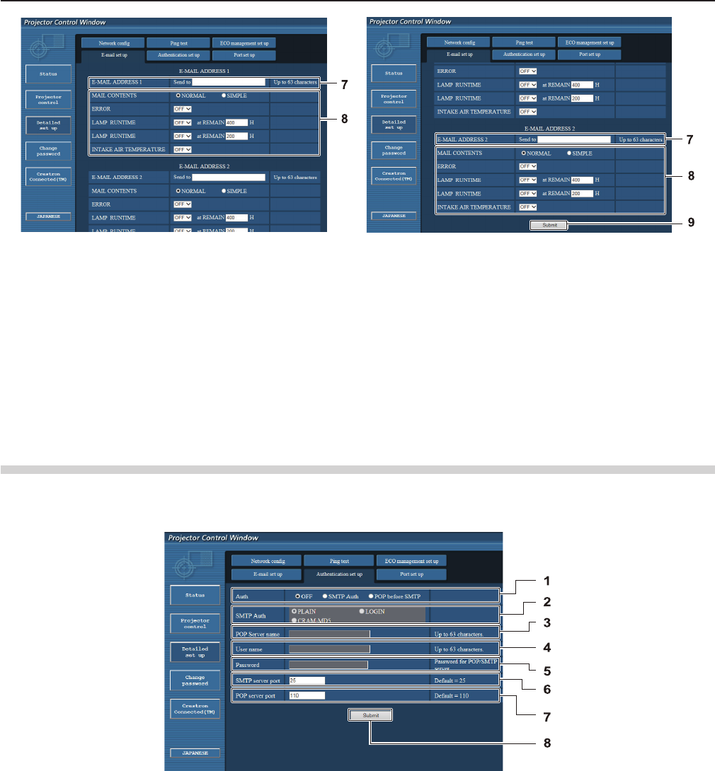
7 [E-MAIL ADDRESS 1]/[E-MAIL ADDRESS 2]
Enter the E-mail address to be sent. Leave [E-MAIL
ADDRESS 2] blank when two E-mail addresses are not
to be used.
8 Settings of the conditions to send E-mail
Select the conditions to send E-mail.
[MAIL CONTENTS]:
Select either [NORMAL] or [SIMPLE].
[ERROR]:
Send an E-mail when an error occurred in the self-
diagnosis.
[LAMP RUNTIME]:
An E-mail message is sent when the remaining lamp on
time for the lamp has reached the value set at the right
eld.
[INTAKE AIR TEMPERATURE]:
Send an E-mail when the air intake temperature has
reached the value set at the above eld.
9 [Submit]
Update the settings.
[Authentication set up] page
Set the authentication items when POP authentication or SMTP authentication is necessary to send an E-mail.
Click [Detailed set up] → [Authentication set up].
1 [Auth]
Select the authentication method specied by your
Internet service provider.
2 [SMTP Auth]
Set when the SMTP authentication is selected.
3 [POP server name]
Enter the POP server name.
Allowed characters:
Alphanumerics (A - Z, a - z, 0 - 9)
Minus sign (-) and period (.)
4 [User name]
Enter the user name for the POP server or the SMTP
server.
5 [Password]
Enter the password for the POP server or the SMTP
server.
6 [SMTP server port]
Enter the port number of the SMTP server.
(Normally 25)
7 [POP server port]
Enter the port number of the POP server.
(Normally 110)
8 [Submit]
Update the settings.
90 - ENGLISH
Chapter 4 Settings - [NETWORK] menu

Contents of mail sent
Example of E-mail sent when E-mail is set
Mail with the contents shown below is sent when the e-mail settings have been established.
=== Panasonic projector report(CONFIGURE) ===
Projector Type : PT-VW350
Serial No : 000000000
----- E-mail setup data -----
TEMPERATURE WARNING SETUP
MINIMUM TIME at [ 60] minutes interval
INTAKE AIR TEMPERATURE Over [ 32degC / 89degF ]
ERROR [ OFF ]
LAMP RUNTIME [ OFF ] at REMAIN [ 400] H
LAMP RUNTIME [ OFF ] at REMAIN [ 200] H
INTAKE AIR TEMPERATURE [ OFF ]
----- check system -----
FAN [ OK ]
INTAKE AIR TEMPERATURE [ OK ]
EXHAUST AIR TEMPERATURE [ OK ]
OPTICS MODULE TEMPERATURE [ OK ]
LAMP REMAIN TIME [ OK ]
LAMP STATUS [ OK ]
APERTURE (CONTRAST-SHUTTER) [ OK ]
AIR FILTER [ OK ]
(Error code 00 00 00 00 00 00 00 00)
Intake air temperature : 31 degC / 87 degF
Exhaust air temperature : 37 degC / 98 degF
Optics module temperature : 39 degC / 102 degF
PROJECTOR RUNTIME 800 H
LAMP NORMAL 500 H
LAMP ECO 700 H
LAMP REMAIN 4000 H
-------- Current status ---------
MAIN VERSION 1.00
NETWORK VERSION 1.00
SUB VERSION 1.00
LAMP STATUS LAMP=ON
INPUT RGB
SIGNAL NAME XGA6
SIGNAL FREQUENCY 0.00kHz / 0.00Hz
----- Wired Network conguration -----
DHCP Client OFF
IP address 192.168.10.100
MAC address 04:20:9A:00:00:00
----- Memo -----
ENGLISH - 91
Chapter 4 Settings - [NETWORK] menu
Example of E-mail sent for an error
Mail with the contents shown below is sent when an error has occurred.
=== Panasonic projector report(ERROR) ===
Projector Type : PT-VW350
Serial No : 000000000
----- check system -----
FAN [ OK ]
INTAKE AIR TEMPERATURE [ OK ]
EXHAUST AIR TEMPERATURE [ OK ]
OPTICS MODULE TEMPERATURE [ OK ]
LAMP REMAIN TIME [ OK ]
LAMP STATUS [ OK ]
APERTURE (CONTRAST-SHUTTER) [ OK ]
AIR FILTER [ FAILED ]
(Error code 00 00 00 20 00 00 00 00)
Intake air temperature : 31 degC / 87 degF
Exhaust air temperature : 37 degC / 98 degF
Optics module temperature : 39 degC / 102 degF
PROJECTOR RUNTIME 800 H
LAMP NORMAL 500 H
LAMP ECO 700 H
LAMP REMAIN 4000 H
-------- Current status ---------
MAIN VERSION 1.00
NETWORK VERSION 1.00
SUB VERSION 1.00
LAMP STATUS LAMP=OFF
INPUT RGB
----- Wired Network conguration -----
DHCP Client OFF
IP address 192.168.10.100
MAC address 04:20:9A:00:00:00
----- Memo -----
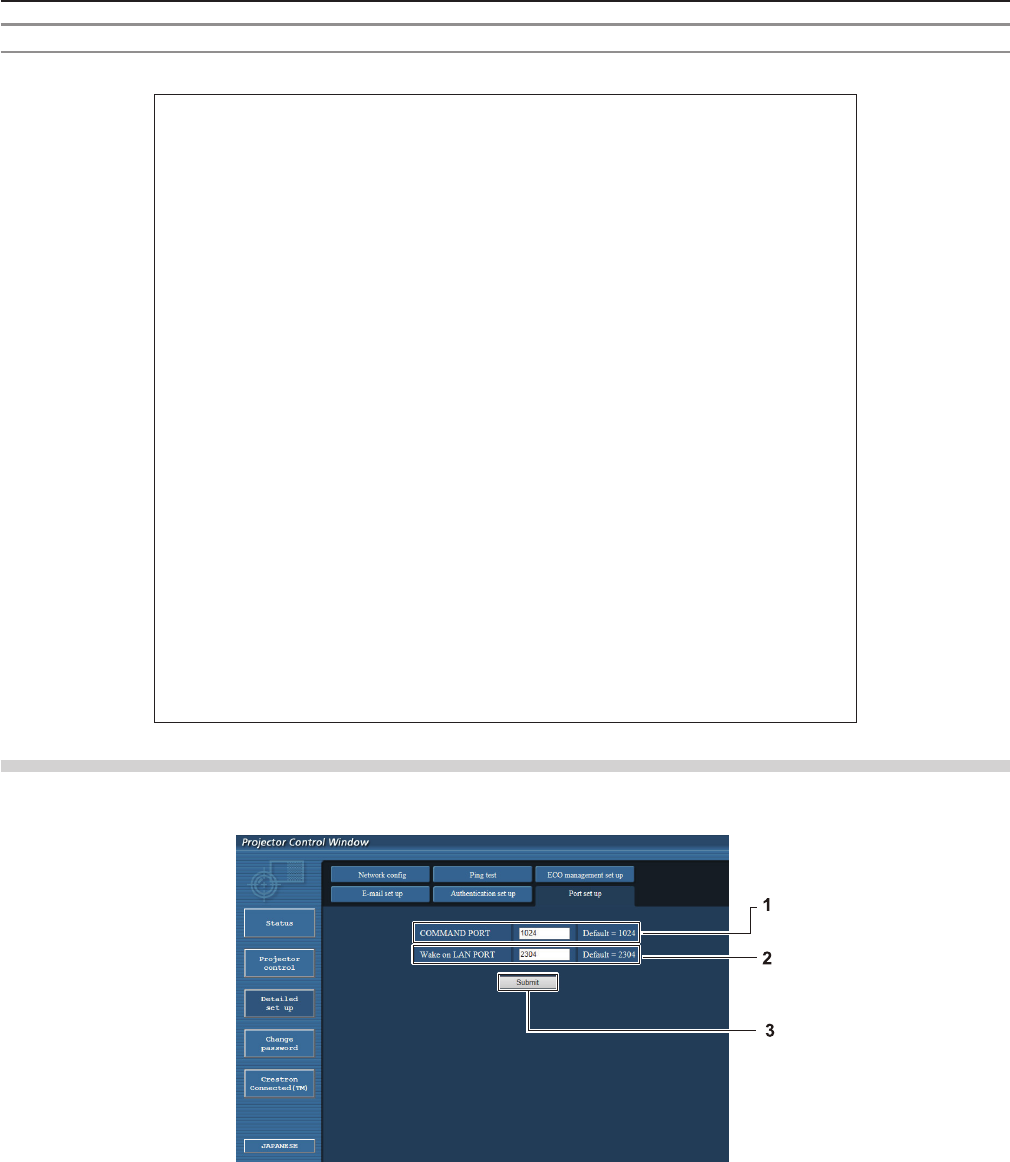
[Port set up] page
Set the port number used for command control.
Click [Detailed set up] → [Port set up].
1 [COMMAND PORT]
Set the port number used for command control.
2 [Wake on LAN PORT]
When [STANDBY MODE] is set to [NETWORK], set the
port number used for the Wake on LAN function.
3 [Submit]
Update the settings.
92 - ENGLISH
Chapter 4 Settings - [NETWORK] menu
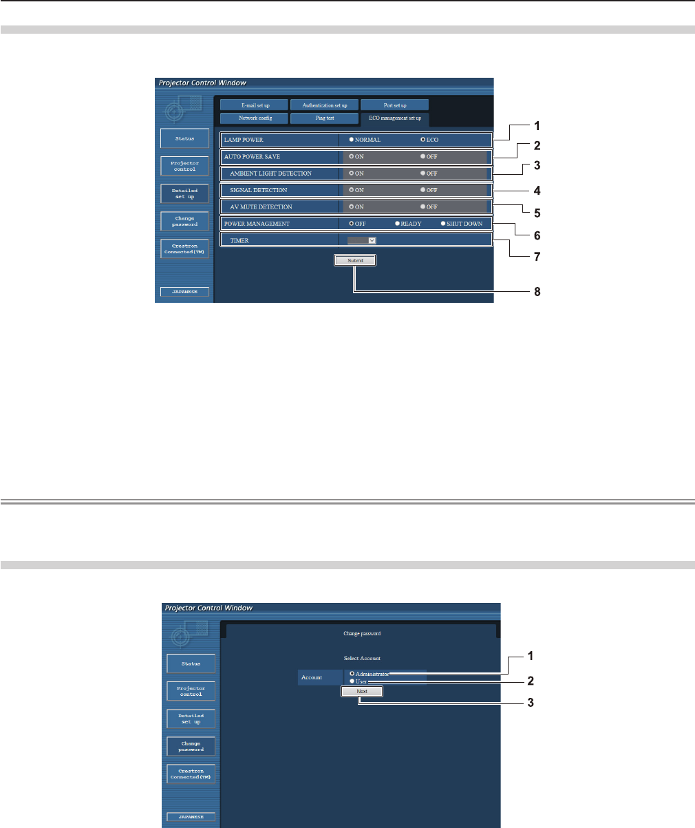
[ECO management set up] page
You can make settings for the ECO management function of the projector.
Click [Detailed set up] → [ECO management set up].
1 [LAMP POWER]
Selects the [LAMP POWER] setting.
2 [AUTO POWER SAVE]
Select [ON] to set [AMBIENT LIGHT DETECTION],
[SIGNAL DETECTION], and [AV MUTE DETECTION].
3 [AMBIENT LIGHT DETECTION]
Enable ([ON])/disable ([OFF]) the ambient light
detection function.
4 [SIGNAL DETECTION]
Enable ([ON])/disable ([OFF]) the signal detection
function.
5 [AV MUTE DETECTION]
Enable ([ON])/disable ([OFF]) the AV mute detection
function.
6 [POWER MANAGEMENT]
Select the power consumption mode.
7 [TIMER]
Select the time that the lamp is turned off when the
POWER MANAGEMENT function is using.
8 [Submit]
Update the setting.
Note
fFor detailed description of each setting item, refer to the [PROJECTOR SETUP] menu of the projector → [ECO
MANAGEMENT] (x page 71).
[Change password] page
Click [Change password].
1 [Administrator]
Used to change the setting of [Administrator].
2 [User]
Used to change the setting of [User].
3 [Next]
Used to change the setting of the password.
ENGLISH - 93
Chapter 4 Settings - [NETWORK] menu
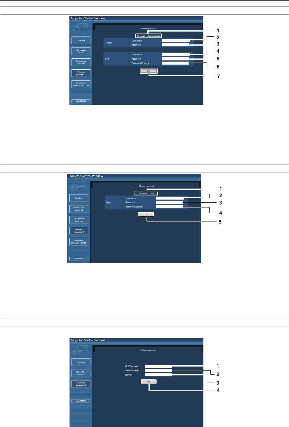
[Administrator] account
1 [Account : Administrator]
Displays the account to change.
2 [Current] [User name]
Enter the user name before the change.
3 [Current] [Password]
Enter the current password.
4 [New] [User name]
Enter the desired new user name.
(Up to 16 characters in single byte)
5 [New] [Password]
Enter the desired new password.
(Up to 16 characters in single byte)
6 [New] [Password (Retype)]
Enter the desired new password again.
7 [OK]
Determines the change of password.
[User] account
1 [Account : User]
Displays the account to change.
2 [New] [User name]
Enter the desired new user name.
(Up to 16 characters in single byte)
3 [New] [Password]
Enter the desired new password. (Up to 16 characters
in single byte)
4 [New] [Password (Retype)]
Enter the desired new password again.
5 [OK]
Determines the change of password.
[Change password] (For user rights)
Only the change of password is enabled under the user rights.
94 - ENGLISH
Chapter 4 Settings - [NETWORK] menu
1 [Old Password]
Enter the current password.
2 [New Password]
Enter the desired new password. (Up to 16 characters
in single byte)
3 [Retype]
Enter the desired new password again.
4 [OK]
Determines the change of password.
Note
fTo change the account of the administrator, you must enter the [User name] and [Password] in [Current].
[Crestron Connected(TM)] page
The projector can be monitored/controlled with Crestron Connected™.
To start the Crestron Connected™ control page from the web control screen, you need to access with the administrator rights.
(For user rights, the [Crestron Connected(TM)] button is not displayed on the web control screen.)
The control page of Crestron Connected™ is displayed by clicking [Crestron Connected(TM)].
It is not displayed if Adobe® Flash® Player is not installed on the computer used, or the browser used does not support Flash.
In that case, click [Back] on the control page to go back to the previous page.
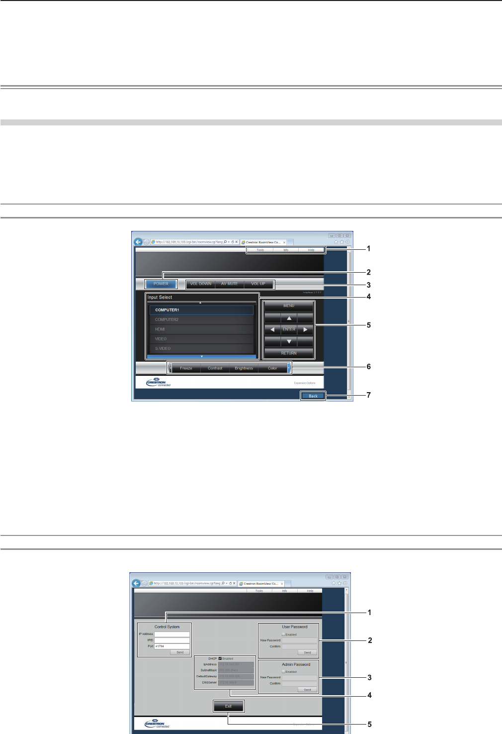
Control page
1 [Tools], [Info], [Help]
Tabs for selecting the setting, information or help
page of the projector.
2 [POWER]
Turns on/off the power.
3 [VOL DOWN], [AV MUTE], [VOL UP]
Adjusts the volume.
Switches the AV mute function on/off.
4 [Input Select]
Controls input selection.
Not available when the power of the projector is turned off.
5 Menu screen control buttons
Navigates the menu screen.
6 Freeze/image quality adjustment
Controls items related to freeze/image quality.
7 [Back]
Performs return to the previous page.
[Tools] page
Click [Tools] on the control page.
ENGLISH - 95
Chapter 4 Settings - [NETWORK] menu
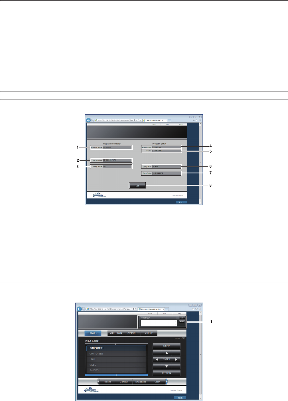
1 [Control System]
Set the information required for communicating with the
controller to be connected with the projector.
2 [User Password]
Set the user rights password for the Crestron
Connected™ control page.
3 [Admin Password]
Set the administrator rights password for the Crestron
Connected™ control page.
4 Network status
Displays the settings of wired LAN.
[DHCP]
Displays the current setting.
[IpAddress]
Displays the current setting.
[SubnetMask]
Displays the current setting.
[DefaultGateway]
Displays the current setting.
[DNSServer]
Displays the current setting.
5 [Exit]
Returns to the control page.
[Info] page
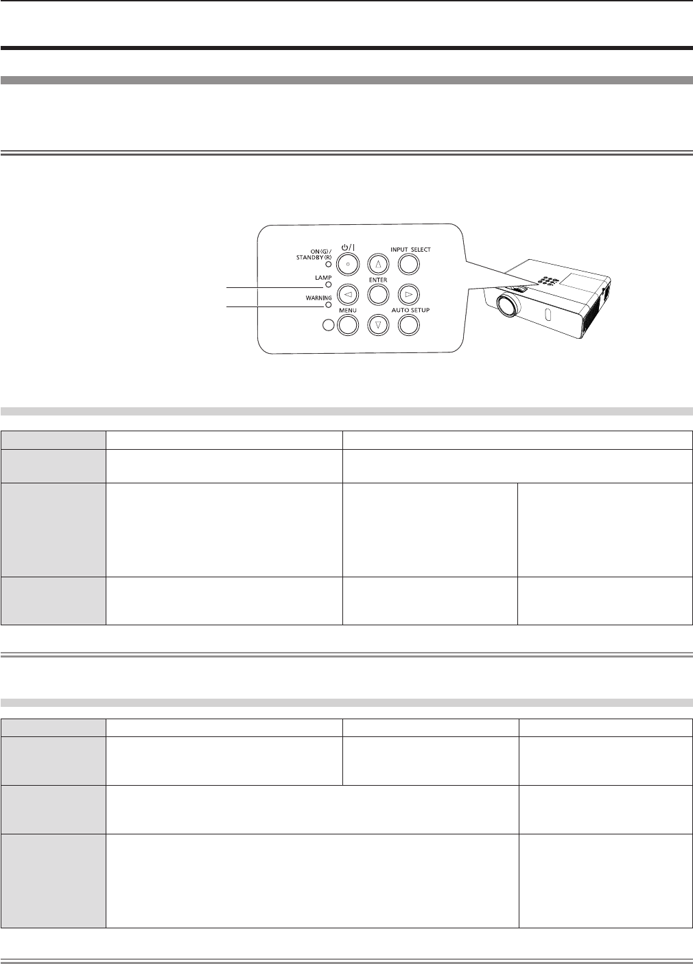
Click [Info] on the control page.
1 [Projector Name]
Displays the projector name.
2 [Mac Address]
Displays the MAC address.
3 [Lamp Hours]
Displays the runtime of the lamp (converted value).
4 [Power Status]
Displays the status of the power.
5 [Source]
Displays the selected input.
6 [Lamp Mode]
Displays the setting status of [LAMP POWER]
(x page 71).
7 [Error Status]
Displays the error status.
8 [Exit]
Returns to the control page.
[Help] page
Click [Help] on the control page.
The [Help Desk] window is displayed.
1 [Help Desk]
Send/receive messages to/from an administrator who uses
Crestron Connected™.
96 - ENGLISH
Chapter 4 Settings - [NETWORK] menu

Chapter 5 Maintenance
This chapter describes methods of inspection when there are problems, maintenance, and
replacement of the units.
ENGLISH - 97
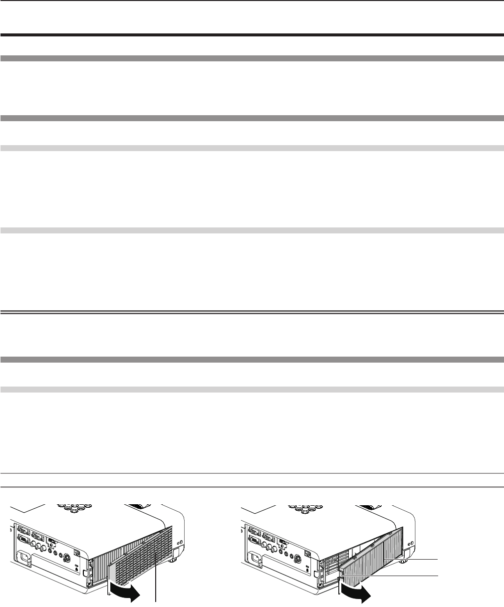
Lamp and Warning Indicators
When an indicator lights up
If a problem should occur inside the projector, the lamp indicator <LAMP> and the warning indicator <WARNING> will inform
you by lighting or blinking. Check the status of the indicators and remedy the indicated problems as follows.
Attention
fBefore you take a remedial measure, follow the procedure of switching the power off indicated in “Powering Off the
projector”. (x page 39)
Lamp indicator
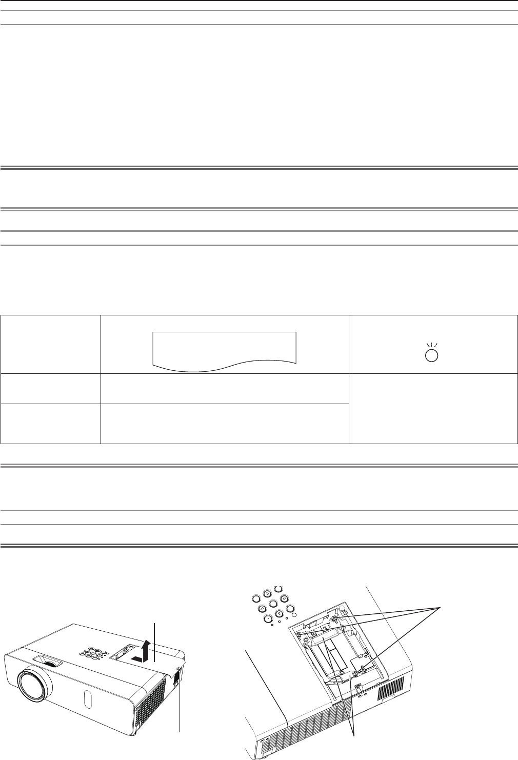
Indicator Lighting in red. Blinking in red.
Status Time to replace the lamp unit. A problem is detected in the lamp or the power supply for the
lamp.
Check
fWas [REPLACE LAMP] displayed when
you turned on the power?
fThe indicator lights up when the
runtime of the lamp unit has reached
5 000 hours (when [LAMP POWER] is
set to [NORMAL]).
fHave you turned on the
power again immediately
after turning it off?
fSome error has occurred in
the lamp circuit. Check for
uctuation (or drop) in the
source voltage.
Remedy fReplace the lamp unit.
fWait a while until the
luminous lamp cools off,
and then turn on the power.
fTurn off the projector, and
unplug the AC power cord,
and consult your dealer.
Note
fIf the lamp indicator <LAMP> is still lighting or blinking after taking the preceding measures, ask your dealer for repair.
Warning indicator
Indicator Lighting in red. Blinking in red. Blinking in red. (Slow)
Status Internal temperature is high (warning). Internal temperature is high
(standby status).
The projector detects an
abnormal condition and
cannot be turned on.
Check
fIs the air intake/exhaust port blocked?
fIs the room temperature high?
fIs the air lter unit dirty?
_
Remedy
fRemove any objects that are blocking the air intake / exhaust port.
fInstall the projector in a location with an ambient temperature of 0 °C
(32 °F) to 40 °C (104 °F).
fDo not use the projector at high altitudes of 2 700 m (8 858') or higher
above sea level.
fReplace the air lter unit. (x page 99)
fIf the projector is turned off
again, unplug the AC power
cord and contact the dealer
or the service center for
service and checkup.
Note
fIf the warning indicator <WARNING> is still lighting or blinking after taking the preceding measures, ask your dealer for
repair.
Lamp indicator <LAMP>
Warning indicator <WARNING>
98 - ENGLISH
Chapter 5 Maintenance - Lamp and Warning Indicators
Maintenance/replacement
Before performing maintenance/replacement
fWhen you perform maintenance or replacement of the parts, make sure to turn off the power and disconnect the power plug
from the wall outlet. (x pages 35, 39)
fBe sure to observe the procedure “Powering Off the projector” (x page 39) when performing power supply operation.
Maintenance
Outer Case
Wipe off dirt and dust using a soft dry cloth.
fIf the dirt is persistent, soak the cloth with water and wring it thoroughly before wiping. Dry off the projector with a dry cloth.
fDo not use benzene, thinner or rubbing alcohol, other solvents or household cleaners. Using them may cause deterioration
of the outer case.
fWhen using chemical treated dusters, follow its instruction.
Front glass surface of the lens
Wipe off the dirt and dust off the front surface of the lens with soft clean cloth.
fDo not use a cloth that has an abrasive surface or a cloth that is moist, oily or covered with dust.
fDo not use excessive force when wiping the lens as it is fragile.
fDo not use benzene, thinner or rubbing alcohol, other solvents or household cleaners. Using them may cause deterioration
of the lens.
Attention
fThe lens is made of glass. Impacts or excessive force when wiping may scratch its surface.
Please handle with care.
Replacing the unit
Air lter unit
The air lter prevents dust from accumulating on the optical elements inside the projector. Should the air lter become clogged
with dust particles, it will reduce cooling fans’ effectiveness and may result in internal heat buildup and adversely affect the life
of the projector.
If the air lter unit become clogged, it will result in internal heat buildup, the power of the projector may be turned off for safety.
If a warning message appears on the screen, replace the air lter immediately.
Consult your dealer to purchase a replacement air lter unit (ET-RFV300).
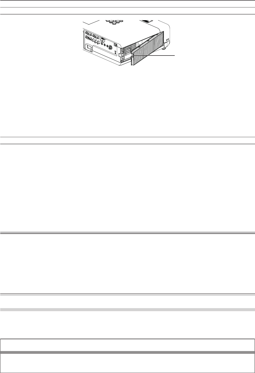
Removing the air lter unit
1) Remove the air filter cover. (Fig.1)
fOpen the air lter cover in the direction of the arrow and remove it.
2) Remove the air filter unit.
fHold the tab of the air lter unit and pull out in the direction of the arrow. (Fig.2)
fAfter removing the air lter unit, remove foreign objects and dust from the air lter compartment and the projector’s air
intake port if there are any.
Air lter unit
Tab
Fig.1 Fig.2
Air lter cover
ENGLISH - 99
Chapter 5 Maintenance - Maintenance/replacement
Attaching the air lter unit
1) Attach the unused air filter unit to the projector.
fHold the air lter unit that the tab is in up-left side in the gure, put the right side in the gure rst, and press the tab side
until make a click sound.
fPlease press the tab of the air lter unit other than the pleated lter during installation.
2) Install the air filter cover.
fPerform Step 1) in “Removing the air lter unit” (x page 99) in the reverse order to close the air lter cover and press
it rmly until make a click sound.
fMake sure that the air lter cover is closed tightly.
Resetting the filter counter
Be sure to reset the lter counter after replacing the air lter unit.
1) Connect the power plug, press the power <v/b> button on the control panel or on the remote control.
2) Press the <MENU> button to display the main menu, then press as to select [PROJECTOR SETUP].
3) Press the <ENTER> button, press as to select [FILTER COUNTER].
4) Press the <ENTER> button, press as to select [FILTER COUNTER RESET].
5) Press the <ENTER> button.
f[FILTER COUNTER RESET] conrmation is displayed.
6) Press qw to select [OK], then press the <ENTER> button.
fThe lter usage time is 0 after reset.
Attention
fTurn off the power before you replace the air lter unit.
fWhen attaching the air lter unit, make sure that the projector is stable, and work in an environment that is safe, even in the
event of the air lter unit dropping.
fMake sure that the air lter unit is properly attached before using the projector. If it is not attached, the projector will suck in
dirt and dust causing a malfunction.
fDo not put anything into the air vents. Doing so may result in malfunction of the projector.
fThe air lter unit to be replaced should be an unused product.
fAfter replacing the air lter, reset the lter counter. Otherwise, “FILTER COUNTER has reached the set time.” will appear on
screen.
Note
fThe replacement cycle of the air lter unit varies greatly depending on the usage environment.
Lamp unit
The lamp unit is a consumable component.
Refer to “When to replace the lamp unit” (x page 101) for details about the replacement cycle.
It is recommended to ask an authorized engineer to replace the lamp unit. Contact your dealer.
Consult your dealer to purchase a replacement lamp unit (ET-LAV300).
Warning
Do not replace the lamp unit when it is hot. (Wait at least 1 hour after use.)
The inside of the cover can become very hot, take care to avoid burn injuries.
Tab
100 - ENGLISH
Chapter 5 Maintenance - Maintenance/replacement
Notes on the replacement of the lamp unit
fThe luminous source of the lamp is made of glass and may burst if you hit it against a hard surface or drop it. Please handle
with care.
fA Phillips screwdriver is required for replacement of the lamp unit.
fWhen replacing the lamp unit, be sure to hold it by the handle.
fWhen replacing the lamp because it has stopped illuminating, there is a possibility that the lamp may be broken. If replacing
the lamp of a projector which has been installed on the ceiling, you should always assume that the lamp is broken, and you
should stand to the side of the lamp cover, not underneath it. Remove the lamp cover gently. Small pieces of glass may fall
out when the lamp cover is opened. If pieces of glass get into your eyes or mouth, seek medical advice immediately.
fThe lamp may be ruptured. Care should be taken not to scatter pieces of the broken lamp glass when replacing the lamp
unit. Pieces of the broken lamp may fall from the lamp unit especially when the projector is mounted on the ceiling, so when
replacing the lamp unit do not stand directly underneath it or position your face close to it.
fThe lamp contains mercury. Consult your local municipality or your dealer about correct disposal of used lamp units.
Attention
fPanasonic takes no responsibility for any damage or malfunction of the product resulting from use of lamp units which are
not manufactured by Panasonic. Use only specied lamp units.
Note
fThe model numbers of accessories and optional accessories are subject to change without prior notice.
When to replace the lamp unit
The lamp unit is a consumable component. Since its brightness gradually decreases over time, it is necessary to replace the
lamp unit regularly. The estimated duration before replacement is 5 000 hours, but the lamp may go off before 5 000 hours has
elapsed depending on individual lamp characteristics, usage conditions, and the installation environment. It is recommended
that the Replacement lamp unit be prepared earlier.
If you continue to use the lamp unit after 5 000 hours has elapsed, the lamp turns off automatically after approximately 10
minutes, as it will cause malfunction of the projector.
Lamp runtime
On-screen display
160 - ENGLISH
REPLACE LAMP
LAMP indicator
Over 4 800 hours The message is displayed for 30 seconds. If you press
any button within the 30 seconds, the message disappears.
Lights in red (even in stand-by mode).
Over 5 000 hours
If the power is turned on without replacing the lamp, the
power automatically turns off after approximately ten min-
utes to prevent the malfunction of the projector.
Note
fTo predict when to replace the lamp, check the lamp runtime displayed in [RUNTIME] in [STATUS] (x page 69).
f5 000 hours of use is a rough guideline, but is not a guarantee. The lamp runtime differs depending on the setting of "LAMP
POWER" menu.
Replacing the Lamp unit
Attention
fWhen the projector is mounted on a ceiling, do not work with your face close to the projector.
fDo not loosen other than designated screws.
fAttach the lamp unit and the lamp cover securely.
Lamp unit xing
screws
Handles
Lamp cover
Lamp cover
xing screw
ENGLISH - 101
Chapter 5 Maintenance - Maintenance/replacement

1) Turn off the Power by following the procedure in "Powering Off the Projector". (x page 39)
Remove the AC power plug from the wall outlet.
fWait at least 1 hour and make sure the lamp unit and surroundings are cool.
2) Use a Phillips screwdriver to loosen the lamp cover fixing screw (×1) until it turns freely and remove
the lamp cover.
fRemove the lamp cover by pulling it slowly toward the direction of the arrow.
3) Use a Phillips screwdriver to loosen the three lamp unit fixing screws (×3) until they turn freely.
4) Hold the used lamp unit by its handles, and pull it gently from the projector.
5) Insert the new lamp unit in correct direction. Tighten the three lamp unit fixing screws (×3) securely
with a Phillips screwdriver.
fWhen you experience difculty in installing the lamp unit, remove it and try again. If you use force to install the lamp
unit, the connector may be damaged.
6) Attach the lamp cover. Tighten the lamp cover fixing screw (×1) securely with a Phillips screwdriver.
fPerform Step 2) in the reverse order to attach the lamp cover.
Note
fWhen you replace the lamp unit with new one, the projector resets the runtime of the lamp unit automatically.
102 - ENGLISH
Chapter 5 Maintenance - Maintenance/replacement

Troubleshooting
Please check following points. For details, see the corresponding pages.
Problem Cause Reference
page
Power does not turn
on.
fThe power cord may not be connected. —
fNo electric supply is at the wall outlet. —
fThe circuit breakers have tripped. —
fIs the <LAMP> indicator or <WARNING > indicator lit or blinking? 98
fThe lamp cover has not been securely installed. 101
No picture appears.
fThe video signal input source may not be connected to a terminal properly. 32
fThe input selection setting may not be correct. 40
fThe [BRIGHTNESS] adjustment setting may be at the minimum setting. 52
fThe input source which is connected to the projector may have a problem. —
fThe AV MUTE function may be in use. 43, 68
The picture is fuzzy.
fThe lens cap is still attached to the lens. 17
fThe lens focus may not have been set correctly. 40
fThe projector may not be at the correct distance from the screen. 27
fThe lens may be dirty. 16
fThe projector may be tilted too much. —
The color is pale or
grayish.
f[COLOR] or [TINT] adjustment may be incorrect. 52
fThe input source which is connected to the projector may not be adjusted correctly.
—
fRGB cable is damaged. —
No sound from the
internal speaker.
fThe input terminals may not have been correctly connected. 33
fThe volume may have been set to the minimum level. 44, 73
fThe AV MUTE function may have been turned on. 43, 68
fWhen the VARIABLE AUDIO OUT is plugged-in, the projector’s built-in speaker
is not available.
33
fThe MUTE function may have been turned on. 44, 73
fIs the audio input selection in [AUDIO SETTING] set correctly? 74
The remote control
does not operate.
fThe batteries may be weak. —
fThe batteries may not have been inserted correctly. 23
fThe remote control signal receptor on the projector may be obstructed. 20
fThe remote control unit may be out of the operation range. 20
fStrong light such as uorescent shine onto the signal receptor. 20
fThe [REMOTE CONTROLLER] setting is set to [DISABLE] in [CONTROL
DEVICE SETUP].
78
fIs the ID number setting operation correct? 45
Menu screen does not
appear.
fIs the on-screen display function turned off (hidden)? 62
The control buttons of
the projector do not
operate.
fThe [CONTROL PANEL] setting is set to [DISABLE] in [CONTROL DEVICE
SETUP].
78
The picture does not
display correctly.
fThere may be a problem with the VCR or other signal source. —
fA signal which is not compatible with the projector is being input. 112
Picture from a
computer does not
appear.
fThe cable may be longer than the optional cable. —
fThe external video output from a laptop computer may not be correct. —
Picture from a HDMI
device does not
appear or picture is
not stable.
fIs the HDMI cable securely connected? 32, 33
fTurn off the power of the projector and the connected devices. Then turn the
power of the projector and the connected devices back on.
—
fIsn’t unsupported signal cable connected? 112
No sound is output
from a HDMI device.
fSet the sound channel of the attached device to Linear PCM. —
Attention
fIf the problem persists, after conrming the contents of the table, please consult your dealer.
ENGLISH - 103
Chapter 5 Maintenance - Troubleshooting

Chapter 6 Appendix
This chapter describes specications and after-sales service for the projector.
104 - ENGLISH
Technical Information
PJLink protocol
The network function of the projector supports PJLink class 1, and the PJLink protocol can be used to perform projector setting
and projector status query operations from a computer.
Control commands
The following table lists the PJLink protocol commands that can be used to control the projector.
fx characters in tables are non-specic characters.
Command Control details Parameter / return
string Remark
POWR Power supply control 0
1
Standby
Power on
POWR ? Power supply status
query
0
1
2
3
Standby
Power on
Cool-down in progress
Warm-up in progress
INPT Input selection 11
12
21
22
31
RGB 1
RGB 2
VIDEO
S-VIDEO
HDMI
INPT ? Input selection query
AVMT AV MUTE control 30
31
AV MUTE mode off
AV MUTE mode on
AVMT ? AV MUTE status query
ERST ? Error status query xxxxxx
1st byte Indicates fan errors,
range 0 – 2.
f 0 = No error is
detected
f 1 = Warning
f 2 = Error
2nd byte Indicates lamp errors,
range 0 – 2
3rd byte Indicates temperature
errors, range 0 – 2.
4th byte Fixed at 0.
5th byte Indicates lter errors,
range 0 – 2.
6th byte Indicates other errors,
range 0 – 2.
LAMP ? Lamp status query xxxxxxxxxxxx 1st digits (1 – 5 digits) : Lamp cumulative operating time
2nd digit : 0 = Lamp off, 1 = Lamp on
INST ? Input selection list query 11 12 21 22 31
NAME ? Projector name query xxxxx Returns the name set in [NAME CHANGE] of [NETWORK].
INF1 ? Manufacturer name query Panasonic Returns manufacturer name.
INF2 ? Model name query VW350
VX420 Returns model name.
INF0 ? Other information query xxxxx Returns information such as version number.
CLSS ? Class information query 1Returns class for PJLink.
PJLink security authorization
The password used for PJLink is the same as that of the password set for web control.
When using the projector without security authentication, do not set a password for web control.
fFor specications related to PJLink, refer to the website of Japan Business Machine and Information System Industries
Association.
URL http://pjlink.jbmia.or.jp/english/
ENGLISH - 105
Chapter 6 Appendix - Technical Information
Control commands via LAN
When WEB Control administrator rights password is set (Protect mode)
Connection method
1) Obtain the IP address and port number (Initial set value = 1 024) of the projector and make a request
for connection to the projector.
fAcquire the IP address from the menu screen of the projector, and the port number from the WEB control page.
IP address : Obtain from MAIN MENU → [NETWORK] → [STATUS]
Port No. : Acquire from the WEB control → [Detailed set up] → [Port set up] page
2) There is a response from the projector.
Data section Blank Mode Blank Random number section Termination symbol
Command
example
“NTCONTROL”
(ASCII string)
‘ ’
0x20
‘1’
0x31
‘ ’
0x20
“zzzzzzzz”
(ASCII code hexadecimal
number)
(CR)
0x0d
Data
length 9 bytes 1 byte 1 byte 1 byte 8 bytes 1 byte
fMode : 1 = Protect mode
3) Generate a 32-byte hash value from the following data using MD5 algorithm.
f“xxxxxx:yyyyy:zzzzzzzz”
xxxxxx : Administrator rights user name for WEB CONTROL (Default user name is “admin1”)
yyyyy : Password of above administrator rights user (Default password is “panasonic”)
zzzzzzzz : 8-byte random number obtained in Step 2
Command transmission method
Transmit using the following command format.
rTransmitted data
Header Data section Termination symbol
Command
example
Hash value
(See above
<Connection method>)
‘0’
0x30
‘0’
0x30
Control command
(ASCII string)
(CR)
0x0d
Data length 32 bytes 1 byte 1 byte Undened length 1 byte
rReceive data
Header Data section Termination symbol
Command
example
‘0’
0x30
‘0’
0x30
Control command
(ASCII string)
(CR)
0x0d
Data length 1 byte 1 byte Undened length 1 byte
rError response
String Details Termination symbol
Message
"ERR1" Undened control command
(CR)
0x0d
"ERR2" Out of parameter range
"ERR3" Busy state or no-acceptable period
"ERR4" Timeout or no-acceptable period
"ERR5" Wrong data length
"ERRA" Password mismatch
Data length 4 bytes ― 1 byte
106 - ENGLISH
Chapter 6 Appendix - Technical Information
When WEB Control administrator rights password is not set (Non-protect mode)
Connection method
1) Obtain the IP address and port number (Initial set value = 1 024) of the projector and make a request
for connection to the projector.
fAcquire the IP address from the menu screen of the projector, and the port number from the WEB control page.
IP address : Obtain from main menu → [NETWORK] → [STATUS]
Port No. : Acquire from the WEB control → [Detailed set up] → [Port set up] page
2) There is a response from the projector.
rResponse data
Data section Blank Mode Termination symbol
Command
example
“NTCONTROL”
(ASCII string)
‘ ’
0x20
‘0’
0x30
(CR)
0x0d
Data length 9 bytes 1 byte 1 byte 1 byte
fMode : 0 = Non-protect mode
Command transmission method
Transmit by the following command format.
rTransmitted data
Header Data section Termination symbol
Command
example
‘0’
0x30
‘0’
0x30
Control command
(ASCII string)
(CR)
0x0d
Data length 1 byte 1 byte Undened length 1 byte
rReceive data
Header Data section Termination symbol
Command
example
‘0’
0x30
‘0’
0x30
Control command
(ASCII string)
(CR)
0x0d
Data length 1 byte 1 byte Undened length 1 byte
rResponse data
String Details Termination symbol
Message
"ERR1" Undened control command
(CR)
0x0d
"ERR2" Out of parameter range
"ERR3" Busy state or no-acceptable period
"ERR4" Timeout or no-acceptable period
"ERR5" Wrong data length
"ERRA" Password mismatch
Data length 4 bytes ― 1 byte
ENGLISH - 107
Chapter 6 Appendix - Technical Information
Serial terminal
The serial connector which is on the connector panel of the projector conforms to the RS-232C interface specication, so that
the projector can be controlled by a personal computer which is connected to this connector.
Connection
Connecting terminals
on projector
D-Sub 9-pin (female) Computer
D-Sub 9-pin (male) Communication cable (straight)
Pin assignments and signal names
D-Sub 9-pin (female)
Outside view Pin No. Signal name Contents
—NC
TXD Transmitted data
RXD Received data
—NC
GND Earth
—NC
CTS Connected internally
RTS
—NC
Communication conditions (Factory default)
Signal level RS-232C-compliant
Sync. method Asynchronous
Baud rate 9 600 bps
Parity None
Character length 8 bits
Stop bit 1 bit
X parameter None
S parameter None
108 - ENGLISH
Chapter 6 Appendix - Technical Information
Basic format
Transmission from the computer starts with STX, then the ID, command, parameter, and ETX are sent in this order. Add
parameters according to the details of control.
STX A D I1 I2 ; C1 C2 C3 : P1 P2 Pn ETX
Basic format (with sub command)
S1 S2 S3 S4 S5 E P1 P2 P3 P4 P5 P6
STX A D I1 I2 ; C1 C2 C3 : ETX
Same as basic format
Sub command (5 bytes)
Operation (1 byte)
“=” (Value specied using parameter is set)
Parameter (6 bytes)*
Symbol “+” or “
-
” (1 byte) and set value or ad-
justment value (5 bytes)
* When transmitting a command which does not need a parameter, the operation (E) and parameter are not necessary.
Attention
fIf a command is transmitted after the lamp starts illuminating, there may be a delay in response or the command may not be
executed. Try sending or receiving any command after 60 seconds.
fWhen transmitting multiple commands, be sure to wait until 0.5 seconds has elapsed after receiving the response from the
projector before sending the next command. When transmitting a command which does not need a parameter, a colon (:) is
not necessary.
Note
fIf a command cannot be executed, the “ER401” response is sent from the projector to the computer.
fIf an invalid parameter is sent, the “ER402” response is sent from the projector to the computer.
fID transmission in RS-232C supports ZZ (ALL) and 01 to 06.
fIf a command is sent with a specied ID, a response will be sent to the computer only in the following cases.
- It matches the projector ID.
- [PROJECTOR ID] (x page 69) is set to [ALL].
fSTX and ETX are character codes. STX shown in hexadecimal is 02, and ETX shown in hexadecimal is 03.
ID designate
ZZ, 01 to 06
Start (1 byte)
(2 byte)
2 ID characters (2 bytes)
Semi-colon(1 byte)
3 command characters (3 bytes)
Colon(1 byte)
Parameter (undened length) End (1 byte)
ENGLISH - 109
Chapter 6 Appendix - Technical Information
Cable specications
[When connected to a computer]
Projector
(<SERIAL IN> terminal)
1NC NC 1
Computer
(DTE specications)
2 2
3 3
4NC NC 4
5 5
6NC NC 6
7 7
8 8
9NC NC 9
Control commands
When controlling the projector from a computer, the following commands are available.
rProjector control command
Command Control contents Parameter / return string Remarks
PON Power on ―To check if the power is on, use the “Power
query” command.
POF Power off
IIS INPUT selection
VID
SVD
RG1
RG2
HD1
VIDEO
S-VIDEO
RGB1
RGB2
HDMI
OSH AV mute function 0
1
AV MUTE mode off
AV MUTE mode on
OFZ Freeze 0[OFF]
1[ON]
AUU Volume up
AUD Volume down
DZU D. ZOOM up
DZD D. ZOOM down
QPW Power query 000 Standby
001 Power on
Q$S Lamp condition query
0
1
2
3
Stand-by
Lamp ON control active
Lamp ON
Lamp OFF control active
[MENU LOCK PASSWORD] operations
To revert to the factory default password (AAAA), perform the following operations while the screen prompting input of [MENU
LOCK PASSWORD] is displayed.
1) Press the <AUTO SETUP> button on the remote control for at least three seconds.
2) Press s for at least three seconds.
110 - ENGLISH
Chapter 6 Appendix - Technical Information
Two window display combination list
Sub Window
COMPUTER1 COMPUTER2
HDMI VIDEO S-VIDEO
Main Window RGB YCBCR/YPBPRRGB
COMPUTER1 RGB ― ― ― l― ―
YCBCR/YPBPR― ― ― l― ―
COMPUTER2 RGB ― ― ― l― ―
HDMI l l l ―l l
VIDEO ― ― ― l― ―
S-VIDEO ― ― ― l― ―
l : Picture in Picture combinations are enabled.
―: Picture in Picture combinations are disabled.
Note
fWhen setting the movie-based signal 1080/24p, 1080/24sF,1080/25p, 1080/30p, 1080/50p or 1080/60p for HDMI input, the
two window display function will be disabled.
fThe image of the sub window picture may be distorted depending on the combination of signals.
fWhen the selected input combinations or the input signals are not correspond with the two window display, the message
"CANNOT DISPLAY THIS INPUT COMBINATION IN P IN P" will be displayed.
ENGLISH - 111
Chapter 6 Appendix - Technical Information

List of compatible signals
The following table species the type of signals compatible with the projectors.
fSymbols that indicate formats are as follows.
V = VIDEO, S = S-VIDEO, R = RGB, Y = YCBCR/YPBPR, H = HDMI
Mode Display resolution
(dots)
Scanning frequency Dot clock
frequency
(MHz)
Format*1
PnP*2
H (kHz) V (Hz) COMPUTER1 /
COMPUTER2 HDMI
NTSC/NTSC4.43/
PAL-M/PAL60 720 x 480i 15.7 59.9 ― V/S ― ―
PAL/PAL-N/SECAM 720 x 576i 15.6 50.0 ― V/S ― ―
525i (480i) 720 x 480i 15.7 59.9 13.5 R/Y ― ―
625i (576i) 720 x 576i 15.6 50.0 13.5 R/Y ― ―
525i (480i) 720 (1 440) x 480i*3 15.7 59.9 27.0 H ― ―
625i (576i) 720 (1 440) x 576i*3 15.6 50.0 27.0 H ― ―
525p (480p) 720 x 483 31.5 59.9 27.0 R/Y/H ―l
625p (576p) 720 x 576 31.3 50.0 27.0 R/Y/H ―l
750 (720) /60p 1 280 x 720 45.0 60.0 74.3 R/Y/H ―l
750 (720) /50p 1 280 x 720 37.5 50.0 74.3 R/Y/H ―l
1125 (1080) /60i*4
1 920 x 1 080i
33.8 60.0 74.3 R/Y/H ―l
1125 (1080) /50i
1 920 x 1 080i
28.1 50.0 74.3 R/Y/H ―l
1125 (1080) /24p
1 920 x 1 080
27.0 24.0 74.3 R/Y/H ―l
1125 (1080) /24sF
1 920 x 1 080i
27.0 48.0 74.3 R/Y/H ― ―
1125 (1080) /25p
1 920 x 1 080
28.1 25.0 74.3 R/Y/H ― ―
1125 (1080) /30p
1 920 x 1 080
33.8 30.0 74.3 R/Y/H ― ―
1125 (1080) /60p
1 920 x 1 080
67.5 60.0 148.5 R/Y/H ―l
1125 (1080) /50p
1 920 x 1 080
56.3 50.0 148.5 R/Y/H ―l
VESA400 640 x 400 31.5 70.1 25.2 R/H ― ―
640 x 400 37.9 85.1 31.5 R/H ― ―
VGA
640 x 480 31.5 59.9 25.2 R/H l l
640 x 480 35.0 66.7 30.2 R/H l―
640 x 480 37.9 72.8 31.5 R/H l―
640 x 480 37.5 75.0 31.5 R/H l―
640 x 480 43.3 85.0 36.0 R/H ― ―
SVGA
800 x 600 35.2 56.3 36.0 R/H l―
800 x 600 37.9 60.3 40.0 R/H l l
800 x 600 48.1 72.2 50.0 R/H l―
800 x 600 46.9 75.0 49.5 R/H l―
800 x 600 53.7 85.1 56.3 R/H ― ―
MAC16 832 x 624 49.7 74.6 57.3 R/H l―
XGA
1 024 x 768 39.6 50.0 51.9 R/H ― ―
1 024 x 768 48.4 60.0 65.0 R/H l l
1 024 x 768 56.5 70.1 75.0 R/H l―
1 024 x 768 60.0 75.0 78.8 R/H l―
1 024 x 768 65.5 81.6 86.0 R/H ― ―
1 024 x 768 68.7 85.0 94.5 R/H ― ―
1 024 x 768 81.4 100.0 113.3 R/H ― ―
MXGA
1 152 x 864 64.0 70.0 94.2 R/H ― ―
1 152 x 864 67.5 75.0 108.0 R/H ― ―
1 152 x 864 77.1 85.0 119.7 R/H ― ―
MAC21 1 152 x 870 68.7 75.1 100.0 R/H ― ―
1280 x 720 1 280 x 720 37.1 50.0 60.5 R/H ― ―
1 280 x 720 44.8 60.0 74.5 R/H ― ―
1280 x 768 1 280 x 768 60.3 74.9 102.3 R/H ― ―
1 280 x 768 68.6 84.8 117.5 R/H ― ―
112 - ENGLISH
Chapter 6 Appendix - Technical Information
Mode Display resolution
(dots)
Scanning frequency Dot clock
frequency
(MHz)
Format*1
PnP*2
H (kHz) V (Hz) COMPUTER1 /
COMPUTER2 HDMI
1280 x 800
1 280 x 800
41.3 50.0 68.0 R/H ― ―
1 280 x 800
49.7 59.8 83.5 R/H l l
MSXGA 1 280 x 960 60.0 60.0 108.0 R/H ― ―
SXGA
1 280 x 1 024
64.0 60.0 108.0 R/H l l
1 280 x 1 024
80.0 75.0 135.0 R/H l―
1 280 x 1 024
91.1 85.0 157.5 R/H ― ―
1366 x 768 1 366 x 768 39.6 49.9 69.0 R/H ― ―
1 366 x 768 47.7 59.8 85.5 R/H l l
SXGA+
1 400 x 1 050
65.2 60.0 122.6 R/H ― ―
1 400 x 1 050
82.3 74.9 156.0 R/H ― ―
WXGA+
1 400 x 900
*5 55.5 59.9 88.8 R/H ― ―
1600 x 900 1 600 x 900 46.3 50.0 97.0 R/H ― ―
1 600 x 900 55.9 60.0 119.0 R/H l l
UXGA
1 600 x 1 200
75.0 60.0 162.0 R/H l l
WSXGA+
1 680 x 1 050
65.2 60.0 147.1 R/H l l
1920 x 1080
1 920 x 1 080
*5 66.6 59.9 138.5 R/H ― ―
WUXGA
1 920 x 1 200
*5 74.0 60.0 154.0 R/H ― ―
*1 <COMPUTER 2 IN> terminal is only for RGB signals input.
*2 Where marked "l" signals indicates in Plug and Play is compatible with EDID of projector. Unmarked signals in Plug and
Play may also be compliant if input terminals are written in the format list. Where Plug and Play is unmarked and nothing is
written in the format list, difculties in projecting image may occur even when computer and projector appear to have same
resolution.
*3 Pixel-Repetition signal (dot clock frequency 27.0 MHz) only
*4 When a 1125 (1035)/60i signal was input, it is displayed as a 1125 (1080)/60i signal.
*5 VESA CVT-RB (Reduced Blanking)-compliant.
Note
fThe number of display dots is 1 280 x 800 for the PT-VW350 and 1 024 x 768 for the PT-VX420.
A signal with a different resolution will be projected after converting the resolution to match the projector display.
f“i” added to the resolution value indicates an interlaced signal.
fWhen interlaced signals are connected, icker may occur on the projected image.
ENGLISH - 113
Chapter 6 Appendix - Technical Information
Specications
Power supply For North America: 120 V (120 V alternating current), 50 Hz/60 Hz
For other countries: 100 V - 240 V (100 V - 240 V alternating current), 50 Hz/60 Hz
Power
con-
sumption
Projecting For North America: 3.2 A, 320 W
For other countries: 3.7 A-1.5 A, 320 W
In standby mode
When [STANDBY MODE] of [ECO MANAGEMENT] is set to [ECO] : 0.5 W *1
When [STANDBY MODE] of [ECO MANAGEMENT] is set to [NETWORK] : 1.6 W *2
When [STANDBY MODE] of [ECO MANAGEMENT] is set to [NORMAL] : 9.5 W
When [STANDBY MODE] of [ECO MANAGEMENT] is set to [NORMAL], and [IN
STANDBY MODE] of [AUDIO SETTING] is set to [ON] : 24 W
LCD
panel
Panel size PT-VW350 1.5 cm (0.59") (aspect ratio 16 : 10)
PT-VX420 1.6 cm (0.63") (aspect ratio 4 : 3)
Display method 3 transparent LCD panels (RGB)
Drive method Active matrix method
Pixels PT-VW350 1 024 000 (1 280 x 800) x 3 panels
PT-VX420 786 432 (1 024 x 768) x 3 panels
Lens Manual zoom : 1.6x
Manual focus : F 1.6 to 1.9, f 15.31 mm to 24.64 mm
Luminous lamp 240 W UHM lamp
Light output *3PT-VW350 4 000 lm
PT-VX420 4 500 lm
Contrast ratio *312 000 : 1 (all white / all black)
([LAMP POWER] is set to [NORMAL], meanwhile [IRIS] is set to [ON])
Appli-
cable
scanning
frequen-
cy *4
for Video signal (in-
cluding S-video)
Horizontal : 15.73 kHz, Vertical : 59.94 Hz
Horizontal : 15.63 kHz, Vertical : 50 Hz
for RGB signal Horizontal 15 kHz to 100 kHz, Vertical 50 Hz to 100 Hz
Dot clock frequency: 140 MHz or less
for YPBPR signal
[525i(480i)] Horizontal 15.73 kHz, Vertical 59.94 Hz
[625i(576i)] Horizontal 15.63 kHz, Vertical 50 Hz
[525p(480p)] Horizontal 31.47 kHz, Vertical 59.94 Hz
[625p(576p)] Horizontal 31.25 kHz, Vertical 50 Hz
[750(720)/60p] Horizontal 45.00 kHz, Vertical 60 Hz
[750(720)/50p] Horizontal 37.50 kHz, Vertical 50 Hz
[1125(1080)/60i] Horizontal 33.75 kHz, Vertical 60 Hz
[1125(1080)/50i] Horizontal 28.13 kHz, Vertical 50 Hz
[1125(1080)/60p] Horizontal 67.50 kHz, Vertical 60 Hz
[1125(1080)/50p] Horizontal 56.25 kHz, Vertical 50 Hz
[1125(1080)/24p] Horizontal 27.00 kHz, Vertical 24 Hz
[1125(1080)/24sF] Horizontal 27.00 kHz, Vertical 48 Hz
[1125(1080)/25p] Horizontal 28.13 kHz, Vertical 25 Hz
[1125(1080)/30p] Horizontal 33.75 kHz, Vertical 30 Hz
for HDMI signal
525i(480i)*5, 625i(576i)*5, 525p(480p), 625p(576p), 750(720)/60p, 750(720)/50p,
1125(1080)/24p,1125(1080)/24sF, 1125(1080)/25p, 1125(1080)/30p, 1125(1080)/60p,
1125(1080)/50p, 1125(1080)/60i, 1125(1080)/50i
Displayable resolution: VGA to WUXGA (non-interlace)
Dot clock frequency: up to 162 MHz
Color system 7 (NTSC, NTSC4.43, PAL, PAL-N, PAL-M, SECAM, PAL60)
*1 When the [PROJECTOR SETUP] menu → [ECO MANAGEMENT] → [STANDBY MODE] is set to [ECO], the network
function cannot be used in standby mode.
*2 When the [PROJECTOR SETUP] menu → [ECO MANAGEMENT] → [STANDBY MODE] is set to [NETWORK], only the
Wake on LAN function can be used in standby mode via wired LAN.
*3 Measurement, measuring conditions and method of notation all comply with ISO21118 international standards.
*4 For details of video signals that can be projected using this projector, refer to “List of compatible signals”.
(x page 112)
*5 Pixel-Repetition signal (dot clock frequency 27.0 MHz) only
114 - ENGLISH
Chapter 6 Appendix - Specications
Projection size 0.76 m -7.62 m (30"-300")
Screen aspect ratio PT-VW350 16 : 10
PT-VX420 4 : 3
Projection scheme
[FRONT/DESK], [FRONT/CEILING], [REAR/DESK], [REAR/CEILING] (Menu setting system)
Speaker 1 (4.0 cm round-type)
Maximum usable volume output 10 W
Terminals
<COMPUTER 1 IN>
1 (High-density D-sub 15 pin female)
[RGB signal] 0.7 V [p-p] 75 Ω (When G-SYNC: 1.0 V [p-p] 75 Ω)
HD/SYNC TTL high impedance, automatic positive/negative polarity compatible
VD TTL high impedance, automatic positive/negative polarity compatible
(SYNC/HD and VD do not support 3 value SYNC.)
[YPBPR signal] Y: 1.0 V [p-p] including synchronization signal, PBPR: 0.7 V [p-p] 75 Ω
<COMPUTER 2 IN/1
OUT>
1 (High-density D-sub 15 pin female)
[RGB signal] 0.7 V [p-p] 75 Ω (When G-SYNC: 1.0 V [p-p] 75 Ω)
HD/SYNC TTL high impedance, automatic positive/negative polarity compatible
VD TTL high impedance, automatic positive/negative polarity compatible
(SYNC/HD and VD do not support 3 value SYNC.)
<VIDEO IN> 1 (Pin jack 1.0 V [p-p] 75 Ω)
<S-VIDEO IN> 1 (Mini DIN 4 pin, Y 1.0 V [p-p], C 0.286 V [p-p] 75 Ω, S1 signal compatible)
<HDMI IN> 1 (HDMI 19 pin, HDCP and Deep color compatible)
Audio signals: Linear PCM (Sampling frequency: 48 kHz/44.1 kHz/32 kHz)
<AUDIO IN>
2 (M3 stereo mini jack, 0.5 V [rms], input impedance 22 kΩ and more)
(<AUDIO IN 2 (MIC IN)> terminal support MIC input)
1 (Pin jack x 2 (L-R), 0.5 V [rms], input impedance 22 kΩ and more)
<VARIABLE AUDIO
OUT>
1 (M3 stereo mini jack, stereo monitor output compatible,
0 V [rms] to 2.0 V [rms] variable, output impedance 2.2 kΩ and less)
<SERIAL IN> 1 (D-sub 9 pin, RS-232C compliant, for computer control use)
<LAN> 1 (for RJ-45 network connection, PJLink compatible,10Base-T/100Base-TX)
Power cable length 2.0 m (78-3/4")
Cabinet Molded plastic
Dimensions
Width: 352 mm (13-7/8")
Height: 98 mm (3-27/32") (when the adjustable feet shortened)
Depth: 279.4 mm (11")
Weight Approx.3.3 kg (7.28 lbs.) *6
Noise level *3When set to [NORMAL] in [LAMP POWER] : 37 dB
When set to [ECO] in [LAMP POWER] : 29 dB
Operating environment
Operating environment temperature *7:
0 °C (32 °F) to 40 °C (104 °F)
(Elevation: below 1 400 m; [HIGH ALTITUDE MODE]: [OFF])
0 °C (32 °F) to 30 °C (86 °F)
(Elevation: 1 400 m ~ 2 000 m; [HIGH ALTITUDE MODE]: [HIGH1])
0 °C (32 °F) to 30 °C (86 °F)
(Elevation: 2 000 m ~ 2 700 m; [HIGH ALTITUDE MODE]: [HIGH2])
Operating environment humidity: 20 % to 80 % (no condensation)
Remote
control
Power supply DC 3 V (battery (AAA/R03 or AAA/LR03 Type ) x 2)
Operating range Approx. 7 m (22'11-5/8") (when operated directly in front of receptor)
Weight 63 g (2.22 ozs.) (including batteries)
Dimensions Width : 44 mm (1-23/32"), Length : 105 mm (4-1/8"), Height : 20.5 mm (13/16")
*6 This is an average value. It may differ depending on individual product.
*7 [LAMP POWER] will be switched to [ECO] automatically when the operating environment temperature is 35 °C to 40 °C.
Note
fThe part numbers of accessories and separately sold components are subject to change without notice.
ENGLISH - 115
Chapter 6 Appendix - Specications
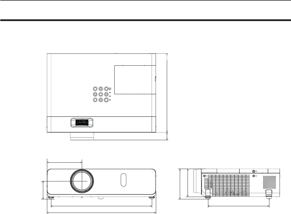
Dimensions
<Unit : mm (inch)>
113.0 (4-7/16")
255.0 (10-1/32")
352.0 (13-7/8")
24.4 (31/32")
98.0 (3-27/32")
90.0 (3-17/32")
326.0 (12-27/32") 198.0 (7-25/32")
54.8 (2-5/32")
* Actual dimension may differ by product.
116 - ENGLISH
Chapter 6 Appendix - Dimensions
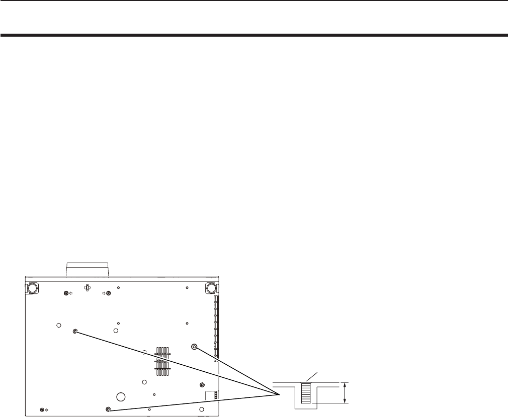
Ceiling mount bracket safeguards
fWhen installing the projector to a ceiling, be sure to use the specied optional Ceiling Mount Bracket for Projectors.
Model No. of ceiling mount bracket:
① ET-PKL100H (for high ceilings), ET-PKV400B (Projector Mount Bracket)
② ET-PKL100S (for low ceilings), ET-PKV400B (Projector Mount Bracket)
fWhen installing the projector, attach the drop-prevention kit included with the Ceiling Mount Bracket for Projectors.
fAsk a qualied technician to do the installation work such as mounting the projector on the ceiling.
fPanasonic takes no responsibility for any damage to the projector resulting from use of a ceiling mount bracket not
manufactured by Panasonic or the inappropriate choice of location for installation, even if the warranty period of the projector
has not expired.
fUnused products must be removed promptly by a qualied technician.
fUse a torque screwdriver or Allen torque wrench to tighten bolts to their specied tightening torques. Do not use electric
screwdrivers or impact screwdrivers.
fRead the Installation Instructions for the Ceiling Mount Bracket for Projectors for details.
fThe model numbers of accessories and optional accessories are subject to change without prior notice.
Bottom view
8 mm (5/16")
Torque: M4 1.25 ± 0.2 N·m
M4 x 0.7
Model No. of ceiling mount bracket:
① ET-PKL100H (for high ceilings)
ET-PKV400B (Projector mount bracket)
② ET-PKL100S (for low ceilings)
ET-PKV400B (Projector mount bracket)
ENGLISH - 117
Chapter 6 Appendix - Ceiling mount bracket safeguards

Index
A
Accessing from the Web browser ......83
Accessories ......................17
<AC IN> terminal ..................20
Adjusting adjustable feet ............29
[ADVANCED MENU] ...............53
[AMX D.D.] .......................80
[ASPECT] ........................59
Attaching the Lens Cap .............24
[AUDIO SETTING] .................73
<AUTO SETUP> button
Projector body ...................21
Remote control ...............19, 41
[AUTO SETUP SETTING] ...........65
<AV MUTE> button
Remote control ..................19
B
[BACK COLOR] ...................65
Basic operations by using the remote
control ...........................41
[BRIGHTNESS] ...................52
C
CD-ROM .........................18
Ceiling mount bracket safeguards ....117
[CLOCK PHASE] ..................58
[CLOSED CAPTION SETTING] .......63
[COLOR] .........................52
[COLOR TEMPERATURE] ...........53
<COMPUTER 1> button
Remote control ...............19, 42
<COMPUTER 2> button
Remote control ...............19, 42
[COMPUTER 2 SELECT] ............69
Connecting .......................30
Connecting the power cord ...........35
[CONTRAST] .....................51
[CONTROL DEVICE SETUP] .........78
[Crestron Connected(TM)] ...........80
D
[DAYLIGHT VIEW] .................53
<DEFAULT> button
Remote control ...............19, 48
Dimensions ......................116
[DISPLAY OPTION] ................62
[DOT CLOCK] .....................58
<D.ZOOM +/-> buttons
Remote control ...............19, 43
E
[ECO MANAGEMENT] ..............71
[EMULATE] .......................72
<ENTER> button
Projector body ...................21
Remote conrol ..................19
F
[FILTER COUNTER] ................75
[FRAME LOCK] ...................60
<FREEZE> button
Remote control ...............19, 42
<FUNCTION> button
Remote control ...............19, 42
[FUNCTION BUTTON] ..............73
H
<HDMI> button
Remote control ...............19, 42
[HDMI SIGNAL LEVEL] .............63
[HIGH ALTITUDE MODE] ............70
I
<ID ALL> button
Remote control ...............19, 45
<ID SET> button
Remote control ...............19, 45
[INITIALIZE] ......................81
[INITIALIZE ALL] ...................75
[INITIAL START UP] ................70
<INPUT SELECT> button
Projector body ...................21
Installation mode ..................26
[IRIS] ............................53
K
[KEYSTONE] .....................56
<KEYSTONE> button
Remote control ...............19, 41
L
Lamp indicator .................21, 98
[LAMP POWER] ...................71
[LANGUAGE] . . . . . . . . . . . . . . . . . . . . . 61
List of compatible signals ...........112
M
Main menu .......................48
Maintenance/replacement ...........99
<MENU> button
Projector body ...................21
Remote control ..................19
[MENU LOCK] ....................77
[MENU LOCK PASSWORD] .........77
Menu Navigation ...................47
<MUTE> button
Remote control ...............19, 44
N
[NAME CHANGE] ..................80
[NETWORK] ......................79
Network connections ...............81
[NETWORK CONTROL] .............80
[NOISE REDUCTION] ..............54
O
[ON-SCREEN DISPLAY] ............62
Optional accessories ...............18
[OTHER FUNCTIONS] ..............67
[OVER SCAN] ....................59
P
[PASSWORD] .....................76
[PASSWORD CHANGE] ............76
[PICTURE] .......................51
[PICTURE MODE] .................51
[P IN P] ..........................67
<P IN P> button
Remote control ...............19, 45
PJLink protocol ...................105
[POSITION] ......................56
Power button
Projector body ...................21
Remote control ..................19
Powering Off the Projector ...........39
Powering On the Projector ...........36
Precautions for use .................14
Projecting . . . . . . . . . . . . . . . . . . . . . . . . 40
[PROJECTION METHOD] ...........70
[PROJECTOR ID] ..................69
[PROJECTOR SETUP] .............69
[P-TIMER] ........................66
<P-TIMER> button
Remote control ...............19, 43
R
Read this rst! ......................2
[REALTIME KEYSTONE] ............56
Remote control ....................19
<RETURN> button
Remote control ...............19, 48
[RGB/YPBPR]/[RGB/YCBCR] ..........55
S
[SCREEN SETTING] ...............64
[SECURITY] ......................76
Setting up ........................26
[SHARPNESS] ....................52
[SHIFT] ..........................58
[SIGNAL SEARCH] ................65
Specications ....................114
[STARTUP LOGO] .................64
[STATUS] .....................69, 81
Sub-menu ........................49
<S-VIDEO> button
Remote control ...............19, 42
[SXGA MODE] ....................65
T
[TEST PATTERN] ..................75
[TEXT CHANGE] ..................77
[TEXT DISPLAY] ..................77
[TINT] ...........................52
Troubleshooting ..................103
[TV-SYSTEM] .....................54
Two window display combination list ..111
V
<VIDEO> button
Remote control ...............19, 42
W
[WIDE MODE] ....................65
[WIRED LAN] .....................79
118 - ENGLISH
Chapter 6 Appendix - Index
M0315HY0 -ST
Product information (for Turkey only)
AEEE Yönetmeliğine Uygundur.
Eski Ekipman ve Bataryaların İşlenmesi.
Sadece geri dönüşüm sistemleri olan Avrupa Birliği ve ülkeleri için geçerlidir.
Ürünler, ambalaj ve/veya ekli belgeler üzerindeki bu semboller kullanılmış elektrik ve elektronik
ürünlerin ve pillerin genel ev atığı ile karıştırılmaması gerektiğini ifade eder.
Eski ürünlerin ve pillerin toplanması ve geri kazanılması için bu atıkları lütfen yasayla belirlenmiş
olan uygun toplama merkezlerine teslim ediniz.
Bu atıkların doğru işlenmesiyle, değerli kaynakların korunmasına ve insan sağlığı ve çevreye
olası negatif etkilerinin engellenmesine yardımcı olabilirsiniz.
Atıkların toplanması ve geri dönüşümü için detaylı bilgi için lütfen bağlı olduğunuz yerel
yönetimlerle iletişime geçiniz.
Atıkların atılmasıyla ilgili yanlış uygulamalar yasayla belirlenmiş olan cezalara sebebiyet verebilir.
Information for Users on Collection and Disposal of Old Equipment and used Batteries
These symbols on the products, packaging, and/or accompanying documents mean that used
electrical and electronic products and batteries should not be mixed with general household
waste. For proper treatment, recovery and recycling of old products and used batteries, please
take them to applicable collection points, in accordance with your national legislation and the
Directives 2002/96/EC and 2006/66/EC.
By disposing of these products and batteries correctly, you will help to save valuable resources
and prevent any potential negative effects on human health and the environment which could
otherwise arise from inappropriate waste handling.
For more information about collection and recycling of old products and batteries, please contact
your local municipality, your waste disposal service or the point of sale where you purchased the
items.
Penalties may be applicable for incorrect disposal of this waste, in accordance with national
legislation.
For business users in the European Union
If you wish to discard electrical and electronic equipment, please contact your dealer or supplier
for further information.
Information on Disposal in other Countries outside the European Union
These symbols are only valid in the European Union. If you wish to discard these items, please
contact your local authorities or dealer and ask for the correct method of disposal.
Note for the battery symbol (bottom two symbol examples):
This symbol might be used in combination with a chemical symbol. In this case it complies with
the requirement set by the Directive for the chemical involved.
Panasonic Corporation
Web Site : http://panasonic.net/avc/projector/
© Panasonic Corporation 2015
Panasonic Systems Communications Company of North America
5th Floor, Two Riverfront Plaza, Newark, NJ 07102-5490
5770 Ambler Drive, Mississauga, Ontario L4W 2T3
TEL: (877) 803 - 8492
TEL: (905) 624 - 5010
Panasonic Canada Inc.