Panasonic of North America PT-VW350 LCD PROJECTOR User Manual PT VW350 Manual Part 3
Panasonic Corporation of North America LCD PROJECTOR PT VW350 Manual Part 3
Contents
- 1. PT-VW350_Manual Part 1-1
- 2. PT-VW350_Manual Part 1-2
- 3. PT-VW350_Manual Part 2
- 4. PT-VW350_Manual Part 3
PT-VW350_Manual Part 3
![7 [E-MAIL ADDRESS 1]/[E-MAIL ADDRESS 2]Enter the E-mail address to be sent. Leave [E-MAIL ADDRESS 2] blank when two E-mail addresses are not to be used.8 Settings of the conditions to send E-mailSelect the conditions to send E-mail. [MAIL CONTENTS]:Select either [NORMAL] or [SIMPLE].[ERROR]:Send an E-mail when an error occurred in the self-diagnosis.[LAMP RUNTIME]:An E-mail message is sent when the remaining lamp on time for the lamp has reached the value set at the right eld.[INTAKE AIR TEMPERATURE]:Send an E-mail when the air intake temperature has reached the value set at the above eld.9 [Submit]Update the settings.[Authentication set up] page Set the authentication items when POP authentication or SMTP authentication is necessary to send an E-mail.Click [Detailed set up] → [Authentication set up].1 [Auth]Select the authentication method specied by your Internet service provider.2 [SMTP Auth]Set when the SMTP authentication is selected.3 [POP server name]Enter the POP server name.Allowed characters:Alphanumerics (A - Z, a - z, 0 - 9)Minus sign (-) and period (.)4 [User name]Enter the user name for the POP server or the SMTP server.5 [Password]Enter the password for the POP server or the SMTP server.6 [SMTP server port]Enter the port number of the SMTP server.(Normally 25)7 [POP server port]Enter the port number of the POP server.(Normally 110)8 [Submit]Update the settings.90 - ENGLISHChapter 4 Settings - [NETWORK] menu](https://usermanual.wiki/Panasonic-of-North-America/PT-VW350.PT-VW350-Manual-Part-3/User-Guide-2596827-Page-1.png)
![Contents of mail sent Example of E-mail sent when E-mail is setMail with the contents shown below is sent when the e-mail settings have been established.=== Panasonic projector report(CONFIGURE) ===Projector Type : PT-VW350Serial No : 000000000----- E-mail setup data -----TEMPERATURE WARNING SETUP MINIMUM TIME at [ 60] minutes interval INTAKE AIR TEMPERATURE Over [ 32degC / 89degF ] ERROR [ OFF ] LAMP RUNTIME [ OFF ] at REMAIN [ 400] H LAMP RUNTIME [ OFF ] at REMAIN [ 200] H INTAKE AIR TEMPERATURE [ OFF ] ----- check system -----FAN [ OK ]INTAKE AIR TEMPERATURE [ OK ]EXHAUST AIR TEMPERATURE [ OK ]OPTICS MODULE TEMPERATURE [ OK ]LAMP REMAIN TIME [ OK ]LAMP STATUS [ OK ]APERTURE (CONTRAST-SHUTTER) [ OK ]AIR FILTER [ OK ](Error code 00 00 00 00 00 00 00 00)Intake air temperature : 31 degC / 87 degF Exhaust air temperature : 37 degC / 98 degF Optics module temperature : 39 degC / 102 degF PROJECTOR RUNTIME 800 HLAMP NORMAL 500 HLAMP ECO 700 HLAMP REMAIN 4000 H-------- Current status ---------MAIN VERSION 1.00NETWORK VERSION 1.00SUB VERSION 1.00LAMP STATUS LAMP=ONINPUT RGBSIGNAL NAME XGA6SIGNAL FREQUENCY 0.00kHz / 0.00Hz----- Wired Network conguration -----DHCP Client OFF IP address 192.168.10.100MAC address 04:20:9A:00:00:00----- Memo -----ENGLISH - 91Chapter 4 Settings - [NETWORK] menu](https://usermanual.wiki/Panasonic-of-North-America/PT-VW350.PT-VW350-Manual-Part-3/User-Guide-2596827-Page-2.png)
![Example of E-mail sent for an errorMail with the contents shown below is sent when an error has occurred.=== Panasonic projector report(ERROR) ===Projector Type : PT-VW350Serial No : 000000000----- check system -----FAN [ OK ]INTAKE AIR TEMPERATURE [ OK ]EXHAUST AIR TEMPERATURE [ OK ]OPTICS MODULE TEMPERATURE [ OK ]LAMP REMAIN TIME [ OK ]LAMP STATUS [ OK ]APERTURE (CONTRAST-SHUTTER) [ OK ]AIR FILTER [ FAILED ](Error code 00 00 00 20 00 00 00 00)Intake air temperature : 31 degC / 87 degF Exhaust air temperature : 37 degC / 98 degF Optics module temperature : 39 degC / 102 degF PROJECTOR RUNTIME 800 HLAMP NORMAL 500 HLAMP ECO 700 HLAMP REMAIN 4000 H-------- Current status ---------MAIN VERSION 1.00 NETWORK VERSION 1.00 SUB VERSION 1.00LAMP STATUS LAMP=OFFINPUT RGB----- Wired Network conguration -----DHCP Client OFF IP address 192.168.10.100MAC address 04:20:9A:00:00:00----- Memo -----[Port set up] pageSet the port number used for command control.Click [Detailed set up] → [Port set up].1 [COMMAND PORT]Set the port number used for command control.2 [Wake on LAN PORT]When [STANDBY MODE] is set to [NETWORK], set the port number used for the Wake on LAN function.3 [Submit]Update the settings.92 - ENGLISHChapter 4 Settings - [NETWORK] menu](https://usermanual.wiki/Panasonic-of-North-America/PT-VW350.PT-VW350-Manual-Part-3/User-Guide-2596827-Page-3.png)
![[ECO management set up] pageYou can make settings for the ECO management function of the projector.Click [Detailed set up] → [ECO management set up].1 [LAMP POWER]Selects the [LAMP POWER] setting.2 [AUTO POWER SAVE]Select [ON] to set [AMBIENT LIGHT DETECTION], [SIGNAL DETECTION], and [AV MUTE DETECTION].3 [AMBIENT LIGHT DETECTION]Enable ([ON])/disable ([OFF]) the ambient light detection function. 4 [SIGNAL DETECTION]Enable ([ON])/disable ([OFF]) the signal detection function.5 [AV MUTE DETECTION]Enable ([ON])/disable ([OFF]) the AV mute detection function.6 [POWER MANAGEMENT]Select the power consumption mode.7 [TIMER]Select the time that the lamp is turned off when the POWER MANAGEMENT function is using.8 [Submit]Update the setting.Note fFor detailed description of each setting item, refer to the [PROJECTOR SETUP] menu of the projector → [ECO MANAGEMENT] (x page 71).[Change password] page Click [Change password].1 [Administrator]Used to change the setting of [Administrator].2 [User]Used to change the setting of [User].3 [Next]Used to change the setting of the password.ENGLISH - 93Chapter 4 Settings - [NETWORK] menu](https://usermanual.wiki/Panasonic-of-North-America/PT-VW350.PT-VW350-Manual-Part-3/User-Guide-2596827-Page-4.png)
![[Administrator] account1 [Account : Administrator]Displays the account to change. 2 [Current] [User name]Enter the user name before the change.3 [Current] [Password]Enter the current password.4 [New] [User name]Enter the desired new user name. (Up to 16 characters in single byte)5 [New] [Password]Enter the desired new password. (Up to 16 characters in single byte)6 [New] [Password (Retype)]Enter the desired new password again.7 [OK]Determines the change of password.[User] account1 [Account : User]Displays the account to change.2 [New] [User name]Enter the desired new user name. (Up to 16 characters in single byte)3 [New] [Password]Enter the desired new password. (Up to 16 characters in single byte)4 [New] [Password (Retype)]Enter the desired new password again.5 [OK]Determines the change of password.[Change password] (For user rights)Only the change of password is enabled under the user rights.94 - ENGLISHChapter 4 Settings - [NETWORK] menu](https://usermanual.wiki/Panasonic-of-North-America/PT-VW350.PT-VW350-Manual-Part-3/User-Guide-2596827-Page-5.png)
![1 [Old Password]Enter the current password.2 [New Password]Enter the desired new password. (Up to 16 characters in single byte)3 [Retype]Enter the desired new password again.4 [OK]Determines the change of password.Note fTo change the account of the administrator, you must enter the [User name] and [Password] in [Current].[Crestron Connected(TM)] page The projector can be monitored/controlled with Crestron Connected™.To start the Crestron Connected™ control page from the web control screen, you need to access with the administrator rights. (For user rights, the [Crestron Connected(TM)] button is not displayed on the web control screen.)The control page of Crestron Connected™ is displayed by clicking [Crestron Connected(TM)].It is not displayed if Adobe® Flash® Player is not installed on the computer used, or the browser used does not support Flash. In that case, click [Back] on the control page to go back to the previous page.Control page1 [Tools], [Info], [Help]Tabs for selecting the setting, information or help page of the projector.2 [POWER]Turns on/off the power.3 [VOL DOWN], [AV MUTE], [VOL UP]Adjusts the volume.Switches the AV mute function on/off.4 [Input Select] Controls input selection. Not available when the power of the projector is turned off.5 Menu screen control buttonsNavigates the menu screen.6 Freeze/image quality adjustmentControls items related to freeze/image quality.7 [Back]Performs return to the previous page.[Tools] pageClick [Tools] on the control page.ENGLISH - 95Chapter 4 Settings - [NETWORK] menu](https://usermanual.wiki/Panasonic-of-North-America/PT-VW350.PT-VW350-Manual-Part-3/User-Guide-2596827-Page-6.png)
![1 [Control System]Set the information required for communicating with thecontroller to be connected with the projector.2 [User Password]Set the user rights password for the Crestron Connected™ control page.3 [Admin Password]Set the administrator rights password for the Crestron Connected™ control page.4 Network statusDisplays the settings of wired LAN.[DHCP]Displays the current setting.[IpAddress]Displays the current setting.[SubnetMask]Displays the current setting.[DefaultGateway]Displays the current setting.[DNSServer]Displays the current setting.5 [Exit]Returns to the control page.[Info] pageClick [Info] on the control page.1 [Projector Name]Displays the projector name.2 [Mac Address]Displays the MAC address.3 [Lamp Hours]Displays the runtime of the lamp (converted value).4 [Power Status]Displays the status of the power.5 [Source]Displays the selected input.6 [Lamp Mode]Displays the setting status of [LAMP POWER] (x page 71).7 [Error Status]Displays the error status.8 [Exit]Returns to the control page.[Help] pageClick [Help] on the control page.The [Help Desk] window is displayed.1 [Help Desk]Send/receive messages to/from an administrator who uses Crestron Connected™.96 - ENGLISHChapter 4 Settings - [NETWORK] menu](https://usermanual.wiki/Panasonic-of-North-America/PT-VW350.PT-VW350-Manual-Part-3/User-Guide-2596827-Page-7.png)
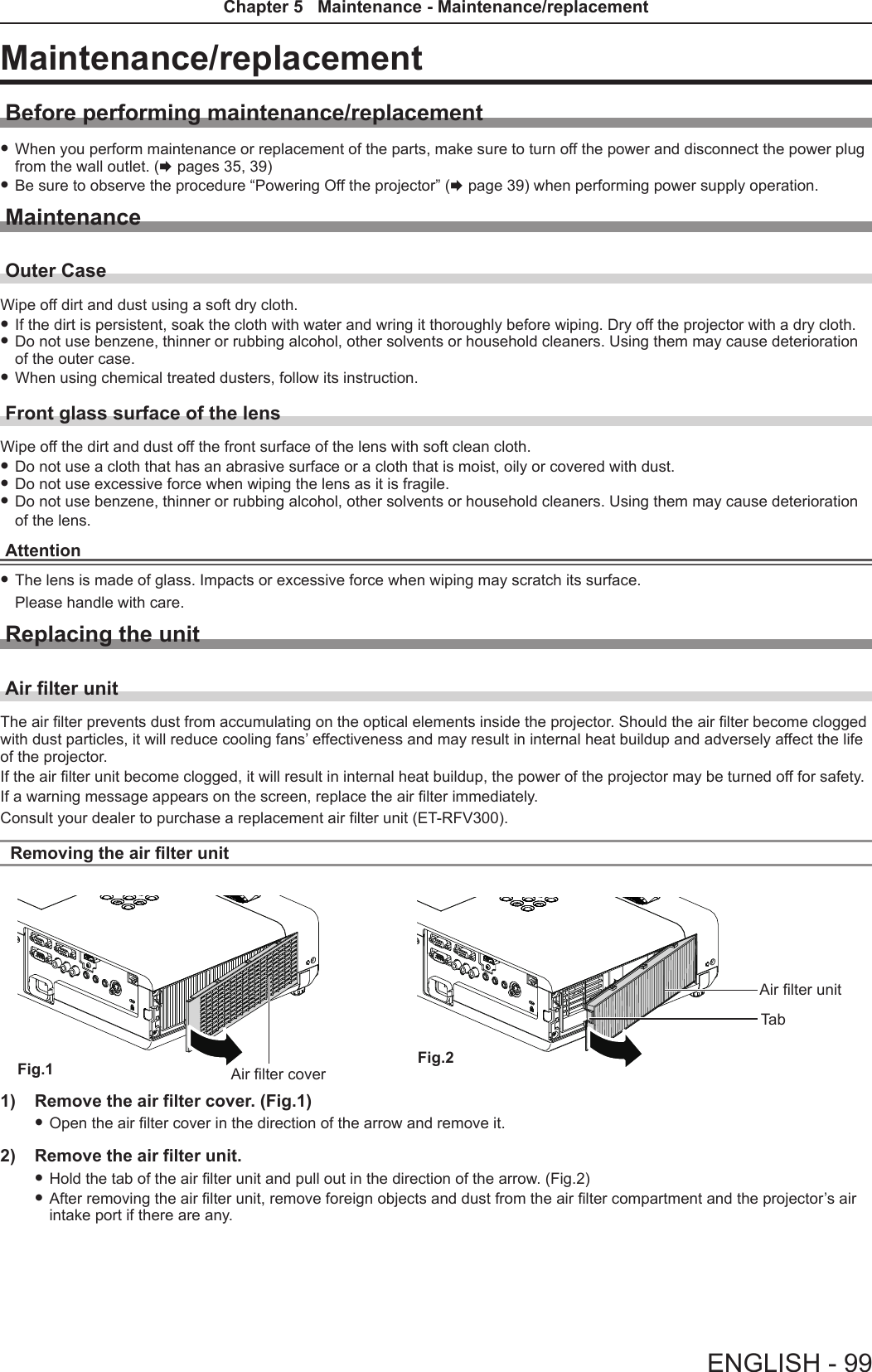
![Lamp and Warning IndicatorsWhen an indicator lights upIf a problem should occur inside the projector, the lamp indicator <LAMP> and the warning indicator <WARNING> will inform you by lighting or blinking. Check the status of the indicators and remedy the indicated problems as follows.Attention fBefore you take a remedial measure, follow the procedure of switching the power off indicated in “Powering Off the projector”. (x page 39)Lamp indicatorIndicator Lighting in red. Blinking in red.Status Time to replace the lamp unit. A problem is detected in the lamp or the power supply for the lamp.Check fWas [REPLACE LAMP] displayed when you turned on the power? fThe indicator lights up when the runtime of the lamp unit has reached 5 000 hours (when [LAMP POWER] is set to [NORMAL]). fHave you turned on the power again immediately after turning it off? fSome error has occurred in the lamp circuit. Check for uctuation (or drop) in the source voltage.Remedy fReplace the lamp unit. fWait a while until the luminous lamp cools off, and then turn on the power. fTurn off the projector, and unplug the AC power cord, and consult your dealer.Note fIf the lamp indicator <LAMP> is still lighting or blinking after taking the preceding measures, ask your dealer for repair.Warning indicatorIndicator Lighting in red. Blinking in red. Blinking in red. (Slow)Status Internal temperature is high (warning). Internal temperature is high (standby status).The projector detects an abnormal condition and cannot be turned on.Check fIs the air intake/exhaust port blocked? fIs the room temperature high? fIs the air lter unit dirty? _Remedy fRemove any objects that are blocking the air intake / exhaust port. fInstall the projector in a location with an ambient temperature of 0 °C (32 °F) to 40 °C (104 °F). fDo not use the projector at high altitudes of 2 700 m (8 858') or higher above sea level. fReplace the air lter unit. (x page 99) fIf the projector is turned off again, unplug the AC power cord and contact the dealer or the service center for service and checkup.Note fIf the warning indicator <WARNING> is still lighting or blinking after taking the preceding measures, ask your dealer for repair.Lamp indicator <LAMP>Warning indicator <WARNING>98 - ENGLISHChapter 5 Maintenance - Lamp and Warning Indicators](https://usermanual.wiki/Panasonic-of-North-America/PT-VW350.PT-VW350-Manual-Part-3/User-Guide-2596827-Page-9.png)
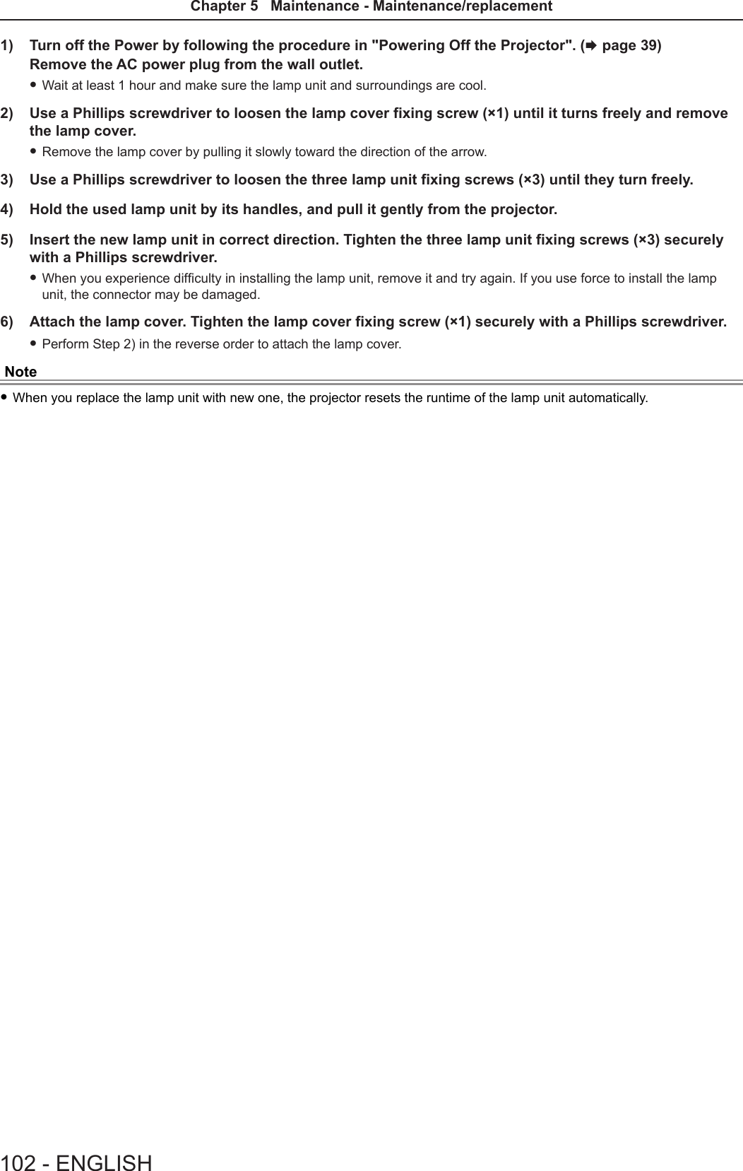
![Attaching the air lter unit1) Attach the unused air filter unit to the projector. fHold the air lter unit that the tab is in up-left side in the gure, put the right side in the gure rst, and press the tab side until make a click sound. fPlease press the tab of the air lter unit other than the pleated lter during installation.2) Install the air filter cover. fPerform Step 1) in “Removing the air lter unit” (x page 99) in the reverse order to close the air lter cover and press it rmly until make a click sound. fMake sure that the air lter cover is closed tightly.Resetting the filter counterBe sure to reset the lter counter after replacing the air lter unit.1) Connect the power plug, press the power <v/b> button on the control panel or on the remote control.2) Press the <MENU> button to display the main menu, then press as to select [PROJECTOR SETUP].3) Press the <ENTER> button, press as to select [FILTER COUNTER].4) Press the <ENTER> button, press as to select [FILTER COUNTER RESET].5) Press the <ENTER> button. f[FILTER COUNTER RESET] conrmation is displayed. 6) Press qw to select [OK], then press the <ENTER> button. fThe lter usage time is 0 after reset.Attention fTurn off the power before you replace the air lter unit. fWhen attaching the air lter unit, make sure that the projector is stable, and work in an environment that is safe, even in the event of the air lter unit dropping. fMake sure that the air lter unit is properly attached before using the projector. If it is not attached, the projector will suck in dirt and dust causing a malfunction. fDo not put anything into the air vents. Doing so may result in malfunction of the projector. fThe air lter unit to be replaced should be an unused product. fAfter replacing the air lter, reset the lter counter. Otherwise, “FILTER COUNTER has reached the set time.” will appear on screen.Note fThe replacement cycle of the air lter unit varies greatly depending on the usage environment.Lamp unitThe lamp unit is a consumable component. Refer to “When to replace the lamp unit” (x page 101) for details about the replacement cycle.It is recommended to ask an authorized engineer to replace the lamp unit. Contact your dealer.Consult your dealer to purchase a replacement lamp unit (ET-LAV300).WarningDo not replace the lamp unit when it is hot. (Wait at least 1 hour after use.)The inside of the cover can become very hot, take care to avoid burn injuries.Tab100 - ENGLISHChapter 5 Maintenance - Maintenance/replacement](https://usermanual.wiki/Panasonic-of-North-America/PT-VW350.PT-VW350-Manual-Part-3/User-Guide-2596827-Page-11.png)
![Notes on the replacement of the lamp unit fThe luminous source of the lamp is made of glass and may burst if you hit it against a hard surface or drop it. Please handle with care. fA Phillips screwdriver is required for replacement of the lamp unit. fWhen replacing the lamp unit, be sure to hold it by the handle. fWhen replacing the lamp because it has stopped illuminating, there is a possibility that the lamp may be broken. If replacing the lamp of a projector which has been installed on the ceiling, you should always assume that the lamp is broken, and you should stand to the side of the lamp cover, not underneath it. Remove the lamp cover gently. Small pieces of glass may fall out when the lamp cover is opened. If pieces of glass get into your eyes or mouth, seek medical advice immediately. fThe lamp may be ruptured. Care should be taken not to scatter pieces of the broken lamp glass when replacing the lamp unit. Pieces of the broken lamp may fall from the lamp unit especially when the projector is mounted on the ceiling, so when replacing the lamp unit do not stand directly underneath it or position your face close to it. fThe lamp contains mercury. Consult your local municipality or your dealer about correct disposal of used lamp units.Attention fPanasonic takes no responsibility for any damage or malfunction of the product resulting from use of lamp units which are not manufactured by Panasonic. Use only specied lamp units.Note fThe model numbers of accessories and optional accessories are subject to change without prior notice.When to replace the lamp unitThe lamp unit is a consumable component. Since its brightness gradually decreases over time, it is necessary to replace the lamp unit regularly. The estimated duration before replacement is 5 000 hours, but the lamp may go off before 5 000 hours has elapsed depending on individual lamp characteristics, usage conditions, and the installation environment. It is recommended that the Replacement lamp unit be prepared earlier.If you continue to use the lamp unit after 5 000 hours has elapsed, the lamp turns off automatically after approximately 10 minutes, as it will cause malfunction of the projector.Lamp runtimeOn-screen display160 - ENGLISHREPLACE LAMPLAMP indicatorOver 4 800 hours The message is displayed for 30 seconds. If you press any button within the 30 seconds, the message disappears.Lights in red (even in stand-by mode).Over 5 000 hoursIf the power is turned on without replacing the lamp, the power automatically turns off after approximately ten min-utes to prevent the malfunction of the projector.Note fTo predict when to replace the lamp, check the lamp runtime displayed in [RUNTIME] in [STATUS] (x page 69). f5 000 hours of use is a rough guideline, but is not a guarantee. The lamp runtime differs depending on the setting of "LAMP POWER" menu.Replacing the Lamp unitAttention fWhen the projector is mounted on a ceiling, do not work with your face close to the projector. fDo not loosen other than designated screws. fAttach the lamp unit and the lamp cover securely.Lamp unit xing screwsHandlesLamp coverLamp cover xing screwENGLISH - 101Chapter 5 Maintenance - Maintenance/replacement](https://usermanual.wiki/Panasonic-of-North-America/PT-VW350.PT-VW350-Manual-Part-3/User-Guide-2596827-Page-12.png)
![TroubleshootingPlease check following points. For details, see the corresponding pages.Problem Cause Reference pagePower does not turn on. fThe power cord may not be connected. — fNo electric supply is at the wall outlet. — fThe circuit breakers have tripped. — fIs the <LAMP> indicator or <WARNING > indicator lit or blinking? 98 fThe lamp cover has not been securely installed. 101No picture appears. fThe video signal input source may not be connected to a terminal properly. 32 fThe input selection setting may not be correct. 40 fThe [BRIGHTNESS] adjustment setting may be at the minimum setting. 52 fThe input source which is connected to the projector may have a problem. — fThe AV MUTE function may be in use. 43, 68The picture is fuzzy. fThe lens cap is still attached to the lens. 17 fThe lens focus may not have been set correctly. 40 fThe projector may not be at the correct distance from the screen. 27 fThe lens may be dirty. 16 fThe projector may be tilted too much. —The color is pale or grayish. f[COLOR] or [TINT] adjustment may be incorrect. 52 fThe input source which is connected to the projector may not be adjusted correctly.— fRGB cable is damaged. —No sound from the internal speaker. fThe input terminals may not have been correctly connected. 33 fThe volume may have been set to the minimum level. 44, 73 fThe AV MUTE function may have been turned on. 43, 68 fWhen the VARIABLE AUDIO OUT is plugged-in, the projector’s built-in speaker is not available.33 fThe MUTE function may have been turned on. 44, 73 fIs the audio input selection in [AUDIO SETTING] set correctly? 74The remote control does not operate. fThe batteries may be weak. — fThe batteries may not have been inserted correctly. 23 fThe remote control signal receptor on the projector may be obstructed. 20 fThe remote control unit may be out of the operation range. 20 fStrong light such as uorescent shine onto the signal receptor. 20 fThe [REMOTE CONTROLLER] setting is set to [DISABLE] in [CONTROL DEVICE SETUP].78 fIs the ID number setting operation correct? 45Menu screen does not appear. fIs the on-screen display function turned off (hidden)? 62The control buttons of the projector do not operate. fThe [CONTROL PANEL] setting is set to [DISABLE] in [CONTROL DEVICE SETUP].78The picture does not display correctly. fThere may be a problem with the VCR or other signal source. — fA signal which is not compatible with the projector is being input. 112Picture from a computer does not appear. fThe cable may be longer than the optional cable. — fThe external video output from a laptop computer may not be correct. —Picture from a HDMI device does not appear or picture is not stable. fIs the HDMI cable securely connected? 32, 33 fTurn off the power of the projector and the connected devices. Then turn the power of the projector and the connected devices back on.— fIsn’t unsupported signal cable connected? 112No sound is output from a HDMI device. fSet the sound channel of the attached device to Linear PCM. —Attention fIf the problem persists, after conrming the contents of the table, please consult your dealer.ENGLISH - 103Chapter 5 Maintenance - Troubleshooting](https://usermanual.wiki/Panasonic-of-North-America/PT-VW350.PT-VW350-Manual-Part-3/User-Guide-2596827-Page-14.png)
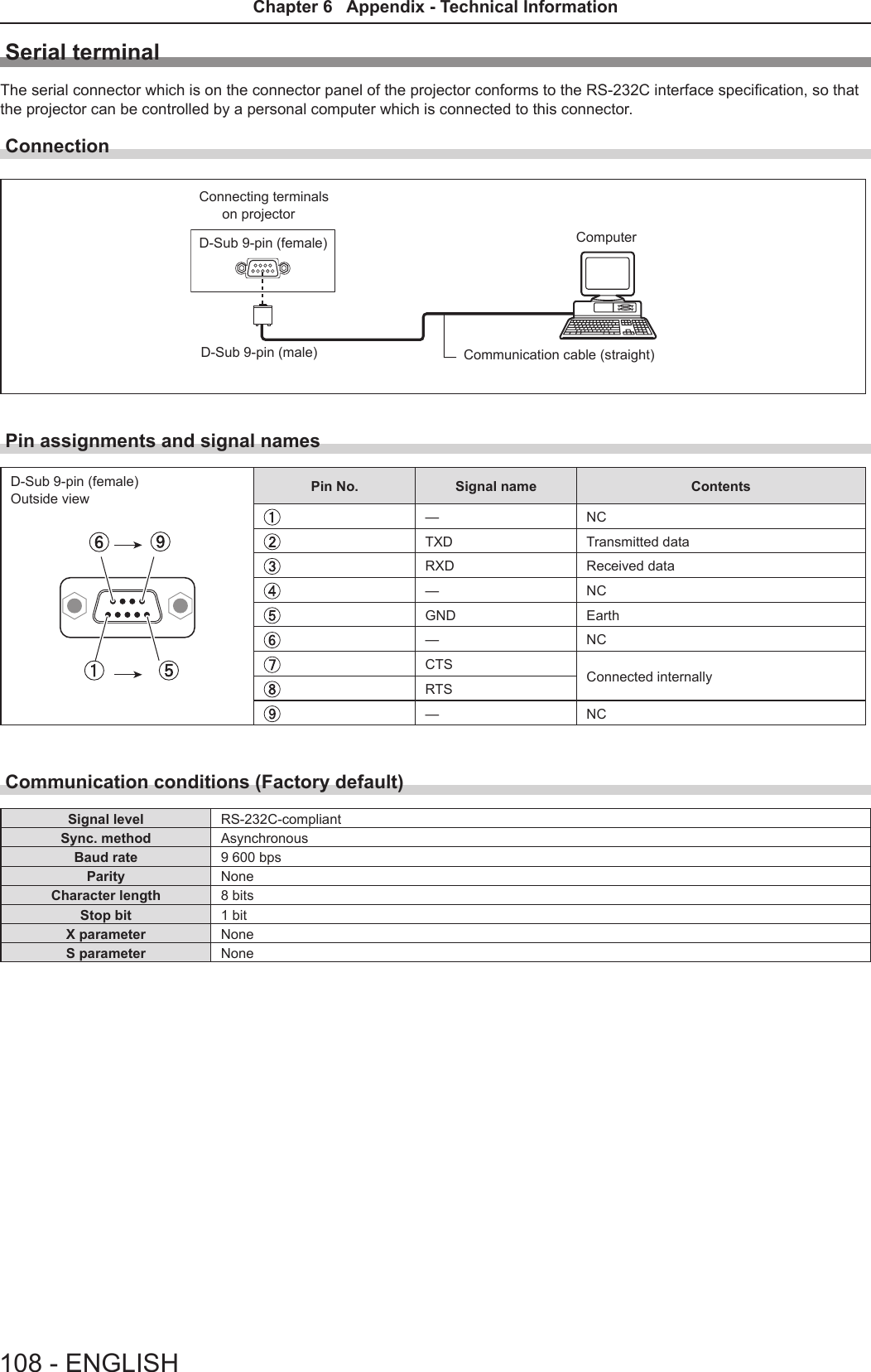
![Technical InformationPJLink protocolThe network function of the projector supports PJLink class 1, and the PJLink protocol can be used to perform projector setting and projector status query operations from a computer.Control commands The following table lists the PJLink protocol commands that can be used to control the projector. fx characters in tables are non-specic characters.Command Control details Parameter / return string RemarkPOWR Power supply control 01StandbyPower onPOWR ? Power supply status query0123StandbyPower onCool-down in progressWarm-up in progressINPT Input selection 1112212231RGB 1RGB 2 VIDEO S-VIDEO HDMI INPT ? Input selection queryAVMT AV MUTE control 30 31AV MUTE mode offAV MUTE mode onAVMT ? AV MUTE status queryERST ? Error status query xxxxxx1st byte Indicates fan errors, range 0 – 2.f 0 = No error is detectedf 1 = Warningf 2 = Error2nd byte Indicates lamp errors, range 0 – 23rd byte Indicates temperature errors, range 0 – 2.4th byte Fixed at 0.5th byte Indicates lter errors, range 0 – 2.6th byte Indicates other errors, range 0 – 2.LAMP ? Lamp status query xxxxxxxxxxxx 1st digits (1 – 5 digits) : Lamp cumulative operating time2nd digit : 0 = Lamp off, 1 = Lamp onINST ? Input selection list query 11 12 21 22 31NAME ? Projector name query xxxxx Returns the name set in [NAME CHANGE] of [NETWORK].INF1 ? Manufacturer name query Panasonic Returns manufacturer name.INF2 ? Model name query VW350VX420 Returns model name.INF0 ? Other information query xxxxx Returns information such as version number.CLSS ? Class information query 1Returns class for PJLink.PJLink security authorization The password used for PJLink is the same as that of the password set for web control.When using the projector without security authentication, do not set a password for web control. fFor specications related to PJLink, refer to the website of Japan Business Machine and Information System Industries Association. URL http://pjlink.jbmia.or.jp/english/ENGLISH - 105Chapter 6 Appendix - Technical Information](https://usermanual.wiki/Panasonic-of-North-America/PT-VW350.PT-VW350-Manual-Part-3/User-Guide-2596827-Page-16.png)
![Control commands via LANWhen WEB Control administrator rights password is set (Protect mode)Connection method 1) Obtain the IP address and port number (Initial set value = 1 024) of the projector and make a request for connection to the projector. fAcquire the IP address from the menu screen of the projector, and the port number from the WEB control page.IP address : Obtain from MAIN MENU → [NETWORK] → [STATUS]Port No. : Acquire from the WEB control → [Detailed set up] → [Port set up] page2) There is a response from the projector.Data section Blank Mode Blank Random number section Termination symbolCommand example“NTCONTROL”(ASCII string)‘ ’0x20‘1’0x31‘ ’0x20“zzzzzzzz”(ASCII code hexadecimal number)(CR)0x0dData length 9 bytes 1 byte 1 byte 1 byte 8 bytes 1 byte fMode : 1 = Protect mode3) Generate a 32-byte hash value from the following data using MD5 algorithm. f“xxxxxx:yyyyy:zzzzzzzz”xxxxxx : Administrator rights user name for WEB CONTROL (Default user name is “admin1”)yyyyy : Password of above administrator rights user (Default password is “panasonic”)zzzzzzzz : 8-byte random number obtained in Step 2Command transmission method Transmit using the following command format. rTransmitted dataHeader Data section Termination symbolCommand exampleHash value(See above <Connection method>)‘0’0x30‘0’0x30Control command(ASCII string)(CR)0x0dData length 32 bytes 1 byte 1 byte Undened length 1 byte rReceive dataHeader Data section Termination symbolCommand example‘0’0x30‘0’0x30Control command(ASCII string)(CR)0x0dData length 1 byte 1 byte Undened length 1 byte rError responseString Details Termination symbolMessage"ERR1" Undened control command(CR)0x0d"ERR2" Out of parameter range"ERR3" Busy state or no-acceptable period"ERR4" Timeout or no-acceptable period"ERR5" Wrong data length"ERRA" Password mismatchData length 4 bytes ― 1 byte106 - ENGLISHChapter 6 Appendix - Technical Information](https://usermanual.wiki/Panasonic-of-North-America/PT-VW350.PT-VW350-Manual-Part-3/User-Guide-2596827-Page-17.png)
![When WEB Control administrator rights password is not set (Non-protect mode)Connection method 1) Obtain the IP address and port number (Initial set value = 1 024) of the projector and make a request for connection to the projector. fAcquire the IP address from the menu screen of the projector, and the port number from the WEB control page.IP address : Obtain from main menu → [NETWORK] → [STATUS]Port No. : Acquire from the WEB control → [Detailed set up] → [Port set up] page2) There is a response from the projector. rResponse dataData section Blank Mode Termination symbolCommand example“NTCONTROL”(ASCII string)‘ ’0x20‘0’0x30(CR)0x0dData length 9 bytes 1 byte 1 byte 1 byte fMode : 0 = Non-protect modeCommand transmission method Transmit by the following command format. rTransmitted dataHeader Data section Termination symbolCommand example‘0’0x30‘0’0x30Control command(ASCII string)(CR)0x0dData length 1 byte 1 byte Undened length 1 byte rReceive dataHeader Data section Termination symbolCommand example‘0’0x30‘0’0x30Control command(ASCII string)(CR)0x0dData length 1 byte 1 byte Undened length 1 byte rResponse dataString Details Termination symbolMessage"ERR1" Undened control command(CR)0x0d"ERR2" Out of parameter range"ERR3" Busy state or no-acceptable period"ERR4" Timeout or no-acceptable period"ERR5" Wrong data length"ERRA" Password mismatchData length 4 bytes ― 1 byteENGLISH - 107Chapter 6 Appendix - Technical Information](https://usermanual.wiki/Panasonic-of-North-America/PT-VW350.PT-VW350-Manual-Part-3/User-Guide-2596827-Page-18.png)
![Basic formatTransmission from the computer starts with STX, then the ID, command, parameter, and ETX are sent in this order. Add parameters according to the details of control.STX A D I1 I2 ; C1 C2 C3 : P1 P2 Pn ETXBasic format (with sub command)S1 S2 S3 S4 S5 E P1 P2 P3 P4 P5 P6STX A D I1 I2 ; C1 C2 C3 : ETXSame as basic formatSub command (5 bytes)Operation (1 byte)“=” (Value specied using parameter is set)Parameter (6 bytes)*Symbol “+” or “-” (1 byte) and set value or ad-justment value (5 bytes)* When transmitting a command which does not need a parameter, the operation (E) and parameter are not necessary.Attention fIf a command is transmitted after the lamp starts illuminating, there may be a delay in response or the command may not be executed. Try sending or receiving any command after 60 seconds. fWhen transmitting multiple commands, be sure to wait until 0.5 seconds has elapsed after receiving the response from the projector before sending the next command. When transmitting a command which does not need a parameter, a colon (:) is not necessary.Note fIf a command cannot be executed, the “ER401” response is sent from the projector to the computer. fIf an invalid parameter is sent, the “ER402” response is sent from the projector to the computer. fID transmission in RS-232C supports ZZ (ALL) and 01 to 06. fIf a command is sent with a specied ID, a response will be sent to the computer only in the following cases. - It matches the projector ID. - [PROJECTOR ID] (x page 69) is set to [ALL]. fSTX and ETX are character codes. STX shown in hexadecimal is 02, and ETX shown in hexadecimal is 03.ID designateZZ, 01 to 06Start (1 byte)(2 byte)2 ID characters (2 bytes)Semi-colon(1 byte)3 command characters (3 bytes)Colon(1 byte)Parameter (undened length) End (1 byte)ENGLISH - 109Chapter 6 Appendix - Technical Information](https://usermanual.wiki/Panasonic-of-North-America/PT-VW350.PT-VW350-Manual-Part-3/User-Guide-2596827-Page-20.png)
![Cable specications[When connected to a computer] Projector(<SERIAL IN> terminal)1NC NC 1Computer(DTE specications)2 23 34NC NC 45 56NC NC 67 78 89NC NC 9Control commandsWhen controlling the projector from a computer, the following commands are available. rProjector control commandCommand Control contents Parameter / return string RemarksPON Power on ―To check if the power is on, use the “Power query” command.POF Power offIIS INPUT selectionVIDSVDRG1RG2HD1VIDEOS-VIDEO RGB1RGB2HDMIOSH AV mute function 01AV MUTE mode offAV MUTE mode on OFZ Freeze 0[OFF]1[ON]AUU Volume upAUD Volume downDZU D. ZOOM upDZD D. ZOOM downQPW Power query 000 Standby001 Power onQ$S Lamp condition query0123Stand-byLamp ON control activeLamp ONLamp OFF control active[MENU LOCK PASSWORD] operationsTo revert to the factory default password (AAAA), perform the following operations while the screen prompting input of [MENU LOCK PASSWORD] is displayed.1) Press the <AUTO SETUP> button on the remote control for at least three seconds.2) Press s for at least three seconds.110 - ENGLISHChapter 6 Appendix - Technical Information](https://usermanual.wiki/Panasonic-of-North-America/PT-VW350.PT-VW350-Manual-Part-3/User-Guide-2596827-Page-21.png)
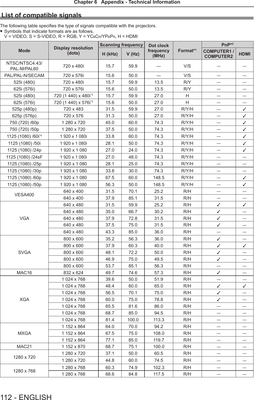
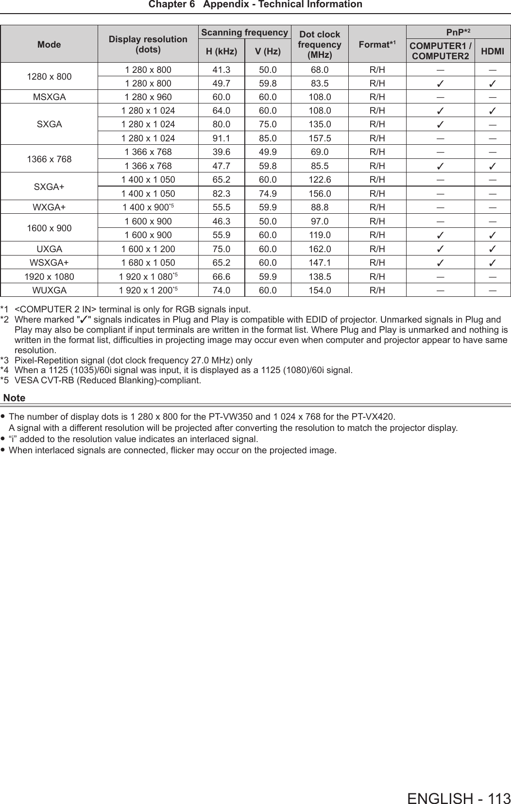
![SpecicationsPower supply For North America: 120 V (120 V alternating current), 50 Hz/60 HzFor other countries: 100 V - 240 V (100 V - 240 V alternating current), 50 Hz/60 HzPower con-sumptionProjecting For North America: 3.2 A, 320 WFor other countries: 3.7 A-1.5 A, 320 WIn standby modeWhen [STANDBY MODE] of [ECO MANAGEMENT] is set to [ECO] : 0.5 W *1When [STANDBY MODE] of [ECO MANAGEMENT] is set to [NETWORK] : 1.6 W *2When [STANDBY MODE] of [ECO MANAGEMENT] is set to [NORMAL] : 9.5 W When [STANDBY MODE] of [ECO MANAGEMENT] is set to [NORMAL], and [IN STANDBY MODE] of [AUDIO SETTING] is set to [ON] : 24 WLCD panelPanel size PT-VW350 1.5 cm (0.59") (aspect ratio 16 : 10)PT-VX420 1.6 cm (0.63") (aspect ratio 4 : 3)Display method 3 transparent LCD panels (RGB)Drive method Active matrix methodPixels PT-VW350 1 024 000 (1 280 x 800) x 3 panelsPT-VX420 786 432 (1 024 x 768) x 3 panelsLens Manual zoom : 1.6xManual focus : F 1.6 to 1.9, f 15.31 mm to 24.64 mmLuminous lamp 240 W UHM lamp Light output *3PT-VW350 4 000 lm PT-VX420 4 500 lmContrast ratio *312 000 : 1 (all white / all black) ([LAMP POWER] is set to [NORMAL], meanwhile [IRIS] is set to [ON])Appli-cable scanning frequen-cy *4for Video signal (in-cluding S-video)Horizontal : 15.73 kHz, Vertical : 59.94 HzHorizontal : 15.63 kHz, Vertical : 50 Hzfor RGB signal Horizontal 15 kHz to 100 kHz, Vertical 50 Hz to 100 HzDot clock frequency: 140 MHz or lessfor YPBPR signal[525i(480i)] Horizontal 15.73 kHz, Vertical 59.94 Hz[625i(576i)] Horizontal 15.63 kHz, Vertical 50 Hz[525p(480p)] Horizontal 31.47 kHz, Vertical 59.94 Hz[625p(576p)] Horizontal 31.25 kHz, Vertical 50 Hz[750(720)/60p] Horizontal 45.00 kHz, Vertical 60 Hz[750(720)/50p] Horizontal 37.50 kHz, Vertical 50 Hz[1125(1080)/60i] Horizontal 33.75 kHz, Vertical 60 Hz[1125(1080)/50i] Horizontal 28.13 kHz, Vertical 50 Hz[1125(1080)/60p] Horizontal 67.50 kHz, Vertical 60 Hz[1125(1080)/50p] Horizontal 56.25 kHz, Vertical 50 Hz[1125(1080)/24p] Horizontal 27.00 kHz, Vertical 24 Hz[1125(1080)/24sF] Horizontal 27.00 kHz, Vertical 48 Hz[1125(1080)/25p] Horizontal 28.13 kHz, Vertical 25 Hz[1125(1080)/30p] Horizontal 33.75 kHz, Vertical 30 Hzfor HDMI signal525i(480i)*5, 625i(576i)*5, 525p(480p), 625p(576p), 750(720)/60p, 750(720)/50p, 1125(1080)/24p,1125(1080)/24sF, 1125(1080)/25p, 1125(1080)/30p, 1125(1080)/60p, 1125(1080)/50p, 1125(1080)/60i, 1125(1080)/50iDisplayable resolution: VGA to WUXGA (non-interlace)Dot clock frequency: up to 162 MHzColor system 7 (NTSC, NTSC4.43, PAL, PAL-N, PAL-M, SECAM, PAL60)*1 When the [PROJECTOR SETUP] menu → [ECO MANAGEMENT] → [STANDBY MODE] is set to [ECO], the network function cannot be used in standby mode.*2 When the [PROJECTOR SETUP] menu → [ECO MANAGEMENT] → [STANDBY MODE] is set to [NETWORK], only the Wake on LAN function can be used in standby mode via wired LAN.*3 Measurement, measuring conditions and method of notation all comply with ISO21118 international standards.*4 For details of video signals that can be projected using this projector, refer to “List of compatible signals”. (x page 112)*5 Pixel-Repetition signal (dot clock frequency 27.0 MHz) only114 - ENGLISHChapter 6 Appendix - Specications](https://usermanual.wiki/Panasonic-of-North-America/PT-VW350.PT-VW350-Manual-Part-3/User-Guide-2596827-Page-25.png)
![Projection size 0.76 m -7.62 m (30"-300")Screen aspect ratio PT-VW350 16 : 10PT-VX420 4 : 3Projection scheme[FRONT/DESK], [FRONT/CEILING], [REAR/DESK], [REAR/CEILING] (Menu setting system)Speaker 1 (4.0 cm round-type)Maximum usable volume output 10 WTerminals<COMPUTER 1 IN>1 (High-density D-sub 15 pin female)[RGB signal] 0.7 V [p-p] 75 Ω (When G-SYNC: 1.0 V [p-p] 75 Ω) HD/SYNC TTL high impedance, automatic positive/negative polarity compatible VD TTL high impedance, automatic positive/negative polarity compatible (SYNC/HD and VD do not support 3 value SYNC.)[YPBPR signal] Y: 1.0 V [p-p] including synchronization signal, PBPR: 0.7 V [p-p] 75 Ω<COMPUTER 2 IN/1 OUT>1 (High-density D-sub 15 pin female)[RGB signal] 0.7 V [p-p] 75 Ω (When G-SYNC: 1.0 V [p-p] 75 Ω) HD/SYNC TTL high impedance, automatic positive/negative polarity compatible VD TTL high impedance, automatic positive/negative polarity compatible (SYNC/HD and VD do not support 3 value SYNC.)<VIDEO IN> 1 (Pin jack 1.0 V [p-p] 75 Ω)<S-VIDEO IN> 1 (Mini DIN 4 pin, Y 1.0 V [p-p], C 0.286 V [p-p] 75 Ω, S1 signal compatible)<HDMI IN> 1 (HDMI 19 pin, HDCP and Deep color compatible) Audio signals: Linear PCM (Sampling frequency: 48 kHz/44.1 kHz/32 kHz) <AUDIO IN>2 (M3 stereo mini jack, 0.5 V [rms], input impedance 22 kΩ and more) (<AUDIO IN 2 (MIC IN)> terminal support MIC input)1 (Pin jack x 2 (L-R), 0.5 V [rms], input impedance 22 kΩ and more)<VARIABLE AUDIO OUT>1 (M3 stereo mini jack, stereo monitor output compatible,0 V [rms] to 2.0 V [rms] variable, output impedance 2.2 kΩ and less)<SERIAL IN> 1 (D-sub 9 pin, RS-232C compliant, for computer control use)<LAN> 1 (for RJ-45 network connection, PJLink compatible,10Base-T/100Base-TX)Power cable length 2.0 m (78-3/4")Cabinet Molded plasticDimensionsWidth: 352 mm (13-7/8")Height: 98 mm (3-27/32") (when the adjustable feet shortened)Depth: 279.4 mm (11")Weight Approx.3.3 kg (7.28 lbs.) *6Noise level *3When set to [NORMAL] in [LAMP POWER] : 37 dBWhen set to [ECO] in [LAMP POWER] : 29 dBOperating environmentOperating environment temperature *7:0 °C (32 °F) to 40 °C (104 °F)(Elevation: below 1 400 m; [HIGH ALTITUDE MODE]: [OFF])0 °C (32 °F) to 30 °C (86 °F)(Elevation: 1 400 m ~ 2 000 m; [HIGH ALTITUDE MODE]: [HIGH1])0 °C (32 °F) to 30 °C (86 °F)(Elevation: 2 000 m ~ 2 700 m; [HIGH ALTITUDE MODE]: [HIGH2])Operating environment humidity: 20 % to 80 % (no condensation)Remote controlPower supply DC 3 V (battery (AAA/R03 or AAA/LR03 Type ) x 2)Operating range Approx. 7 m (22'11-5/8") (when operated directly in front of receptor)Weight 63 g (2.22 ozs.) (including batteries)Dimensions Width : 44 mm (1-23/32"), Length : 105 mm (4-1/8"), Height : 20.5 mm (13/16")*6 This is an average value. It may differ depending on individual product.*7 [LAMP POWER] will be switched to [ECO] automatically when the operating environment temperature is 35 °C to 40 °C.Note fThe part numbers of accessories and separately sold components are subject to change without notice.ENGLISH - 115Chapter 6 Appendix - Specications](https://usermanual.wiki/Panasonic-of-North-America/PT-VW350.PT-VW350-Manual-Part-3/User-Guide-2596827-Page-26.png)
![IndexAAccessing from the Web browser ......83Accessories ......................17<AC IN> terminal ..................20Adjusting adjustable feet ............29[ADVANCED MENU] ...............53[AMX D.D.] .......................80[ASPECT] ........................59Attaching the Lens Cap .............24[AUDIO SETTING] .................73<AUTO SETUP> buttonProjector body ...................21Remote control ...............19, 41[AUTO SETUP SETTING] ...........65<AV MUTE> buttonRemote control ..................19B[BACK COLOR] ...................65Basic operations by using the remote control ...........................41[BRIGHTNESS] ...................52CCD-ROM .........................18Ceiling mount bracket safeguards ....117[CLOCK PHASE] ..................58[CLOSED CAPTION SETTING] .......63[COLOR] .........................52[COLOR TEMPERATURE] ...........53<COMPUTER 1> buttonRemote control ...............19, 42<COMPUTER 2> buttonRemote control ...............19, 42[COMPUTER 2 SELECT] ............69Connecting .......................30Connecting the power cord ...........35[CONTRAST] .....................51[CONTROL DEVICE SETUP] .........78[Crestron Connected(TM)] ...........80D[DAYLIGHT VIEW] .................53<DEFAULT> buttonRemote control ...............19, 48Dimensions ......................116[DISPLAY OPTION] ................62[DOT CLOCK] .....................58<D.ZOOM +/-> buttonsRemote control ...............19, 43E[ECO MANAGEMENT] ..............71[EMULATE] .......................72<ENTER> buttonProjector body ...................21Remote conrol ..................19F[FILTER COUNTER] ................75[FRAME LOCK] ...................60<FREEZE> buttonRemote control ...............19, 42<FUNCTION> buttonRemote control ...............19, 42[FUNCTION BUTTON] ..............73H<HDMI> buttonRemote control ...............19, 42[HDMI SIGNAL LEVEL] .............63[HIGH ALTITUDE MODE] ............70I<ID ALL> buttonRemote control ...............19, 45<ID SET> buttonRemote control ...............19, 45[INITIALIZE] ......................81[INITIALIZE ALL] ...................75[INITIAL START UP] ................70<INPUT SELECT> buttonProjector body ...................21Installation mode ..................26[IRIS] ............................53K[KEYSTONE] .....................56<KEYSTONE> buttonRemote control ...............19, 41LLamp indicator .................21, 98[LAMP POWER] ...................71[LANGUAGE] . . . . . . . . . . . . . . . . . . . . . 61List of compatible signals ...........112MMain menu .......................48Maintenance/replacement ...........99<MENU> buttonProjector body ...................21Remote control ..................19[MENU LOCK] ....................77[MENU LOCK PASSWORD] .........77Menu Navigation ...................47<MUTE> buttonRemote control ...............19, 44N[NAME CHANGE] ..................80[NETWORK] ......................79Network connections ...............81[NETWORK CONTROL] .............80[NOISE REDUCTION] ..............54O[ON-SCREEN DISPLAY] ............62Optional accessories ...............18[OTHER FUNCTIONS] ..............67[OVER SCAN] ....................59P[PASSWORD] .....................76[PASSWORD CHANGE] ............76[PICTURE] .......................51[PICTURE MODE] .................51[P IN P] ..........................67<P IN P> buttonRemote control ...............19, 45PJLink protocol ...................105[POSITION] ......................56Power buttonProjector body ...................21Remote control ..................19Powering Off the Projector ...........39Powering On the Projector ...........36Precautions for use .................14Projecting . . . . . . . . . . . . . . . . . . . . . . . . 40[PROJECTION METHOD] ...........70[PROJECTOR ID] ..................69[PROJECTOR SETUP] .............69[P-TIMER] ........................66<P-TIMER> buttonRemote control ...............19, 43RRead this rst! ......................2[REALTIME KEYSTONE] ............56Remote control ....................19<RETURN> buttonRemote control ...............19, 48[RGB/YPBPR]/[RGB/YCBCR] ..........55S[SCREEN SETTING] ...............64[SECURITY] ......................76Setting up ........................26[SHARPNESS] ....................52[SHIFT] ..........................58[SIGNAL SEARCH] ................65Specications ....................114[STARTUP LOGO] .................64[STATUS] .....................69, 81Sub-menu ........................49<S-VIDEO> buttonRemote control ...............19, 42[SXGA MODE] ....................65T[TEST PATTERN] ..................75[TEXT CHANGE] ..................77[TEXT DISPLAY] ..................77[TINT] ...........................52Troubleshooting ..................103[TV-SYSTEM] .....................54Two window display combination list ..111V<VIDEO> buttonRemote control ...............19, 42W[WIDE MODE] ....................65[WIRED LAN] .....................79118 - ENGLISHChapter 6 Appendix - Index](https://usermanual.wiki/Panasonic-of-North-America/PT-VW350.PT-VW350-Manual-Part-3/User-Guide-2596827-Page-29.png)