Panasonic of North America PT-VW350 LCD PROJECTOR User Manual PT VW350 Manual Part 1 2
Panasonic Corporation of North America LCD PROJECTOR PT VW350 Manual Part 1 2
Contents
- 1. PT-VW350_Manual Part 1-1
- 2. PT-VW350_Manual Part 1-2
- 3. PT-VW350_Manual Part 2
- 4. PT-VW350_Manual Part 3
PT-VW350_Manual Part 1-2
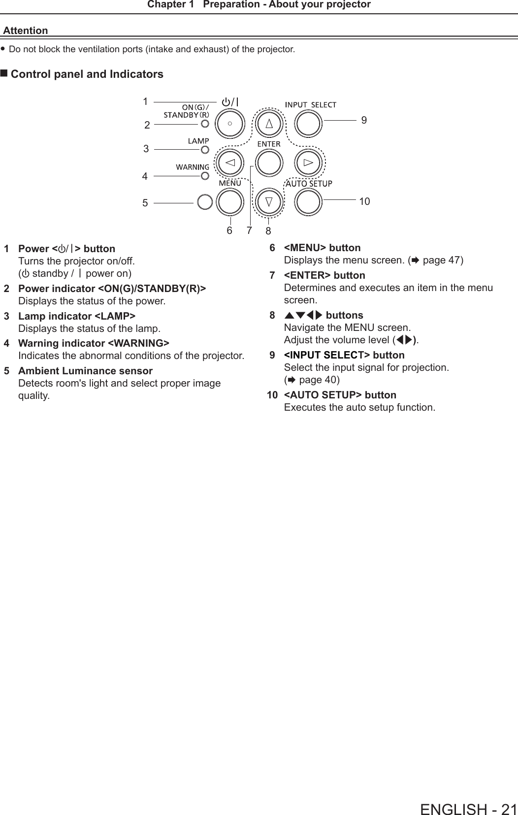
![Preparing the remote controlInserting and removing batteries(i)(ii) (i)(ii)1) Open the cover. (Fig. 1)2) Insert batteries and close the cover. (Insert the m side first.) (Fig. 2) fWhen removing the batteries, perform the steps in reverse order.When using the system with multiple projectorsWhen you use the system with multiple projectors, you can operate all the projectors simultaneously or each projector individually by using single remote control, if a unique ID number is assigned to each projector.When you want to set the ID number, at rst you need to complete the Initial setting, and then after setting the ID number of the projector, set the ID number on the remote control. About Initial setting, please refer to “When the initial setting screen is displayed” (x page 36).The factory default ID number of the unit (the projector and the remote control) is set to [ALL], you can control with this setting. If necessary, please set the ID number to the remote control and the projector. About how to set the ID number of the remote control, please refer to “Setting the ID number of the remote control” (x page 45).Note fSet the ID number of the projector from the [PROJECTOR SETUP] menu → [PROJECTOR ID]. (x page 69)Fig. 2Fig. 1ENGLISH - 23Chapter 1 Preparation - Preparing the remote control](https://usermanual.wiki/Panasonic-of-North-America/PT-VW350.PT-VW350-Manual-Part-1-2/User-Guide-2596825-Page-3.png)
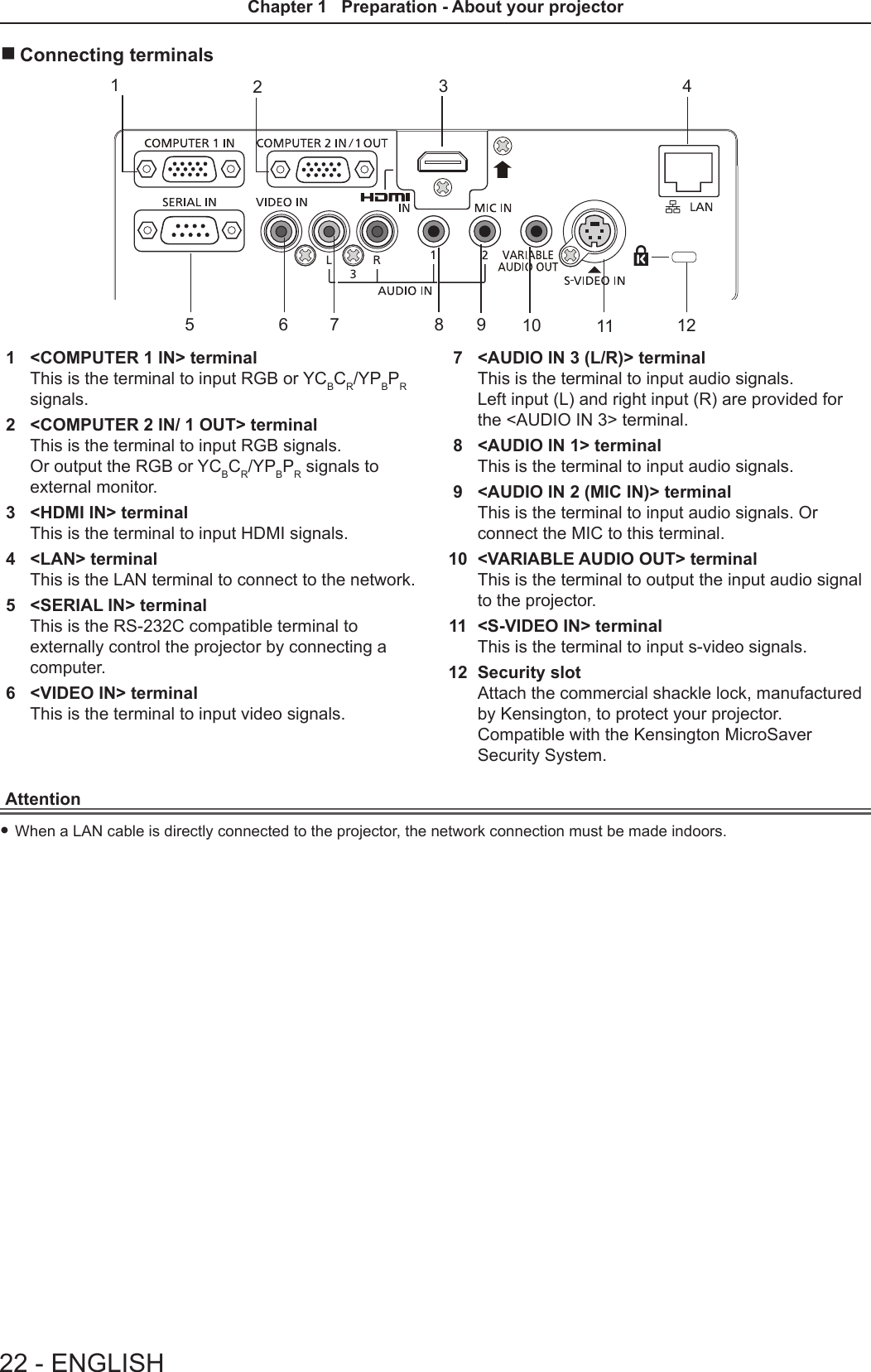
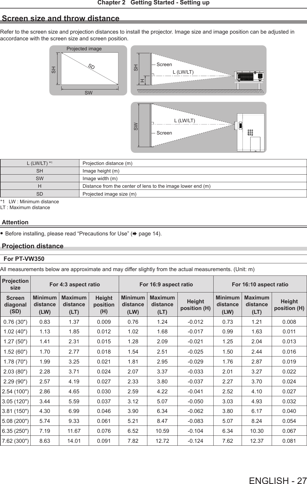
![Setting upInstallation modeThere are four ways to set up the projector. Set the [PROJECTOR SETUP] menu → [PROJECTION METHOD] (x page 70) depending on the installation location. Mounting on the ceiling and projecting forward Setting on a desk/oor and projecting from rear(Using the translucent screen)Menu item Method Menu item Method[PROJECTION METHOD] [FRONT/CEILING] [PROJECTION METHOD] [REAR/DESK]Mounting on the ceiling and projecting from rear(Using the translucent screen)Setting on a desk/oor and projecting forwardMenu item Method Menu item Method[PROJECTION METHOD] [REAR/CEILING] [PROJECTION METHOD] [FRONT/DESK]Parts for ceiling mount (optional)This requires an optional ceiling mount bracket. Be sure to use the Projector Mount Bracket together with the ceiling mount bracket for high ceilings or low ceilings. Model No.: ① ET-PKL100H (for high ceilings), ET-PKV400B (Projector Mount Bracket) ② ET-PKL100S (for low ceilings), ET-PKV400B (Projector Mount Bracket) fUse only the ceiling mount brackets specied for this projector. fRefer to the Installation Instructions for the ceiling mount bracket when you install the bracket and the projector.Attention fTo ensure projector performance and security, installation of the ceiling mount bracket must be carried by your dealer or a qualied technician.26 - ENGLISHChapter 2 Getting Started - Setting up](https://usermanual.wiki/Panasonic-of-North-America/PT-VW350.PT-VW350-Manual-Part-1-2/User-Guide-2596825-Page-6.png)
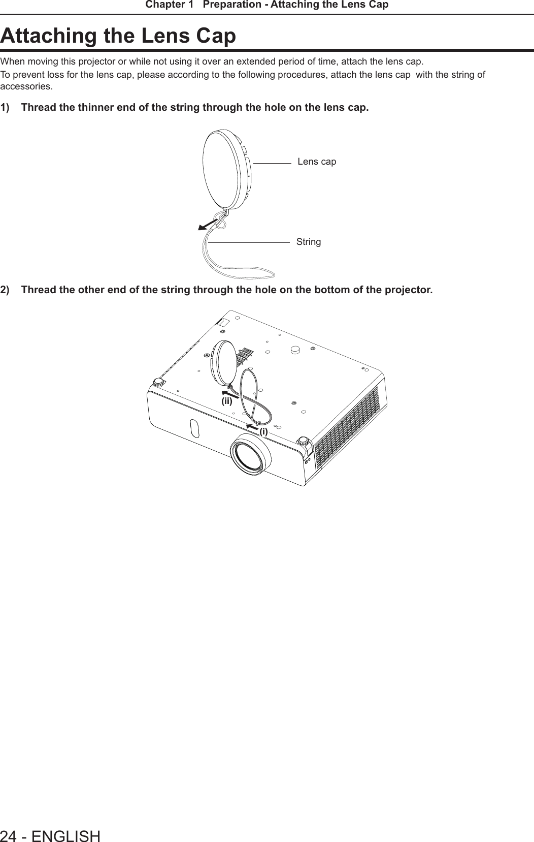
![Adjusting adjustable feetLift the front of the projector and press the feet lock latches on both side of the projector.Release the feet lock latches to lock the adjustable feet and rotate the adjustable feet to a proper height and tilt.Extend the adjustable feet by rotating in the direction shown in the gure and retract by rotating in the opposite direction.Feet lock latchesAttention fHeated air comes out of the air exhaust port while the lamp is lit. Do not touch the air exhaust port directly when you adjust the adjustable feet. fIf keystone distortion occurs on the projected image, perform [KEYSTONE] from the [POSITION] menu. (x page 56)Note fScrew up the adjustable feet, and an audible click will be heard as the limit.Adjustable rangeAdjustable feet : 43 mm (1-11/16")ENGLISH - 29Chapter 2 Getting Started - Setting up](https://usermanual.wiki/Panasonic-of-North-America/PT-VW350.PT-VW350-Manual-Part-1-2/User-Guide-2596825-Page-9.png)
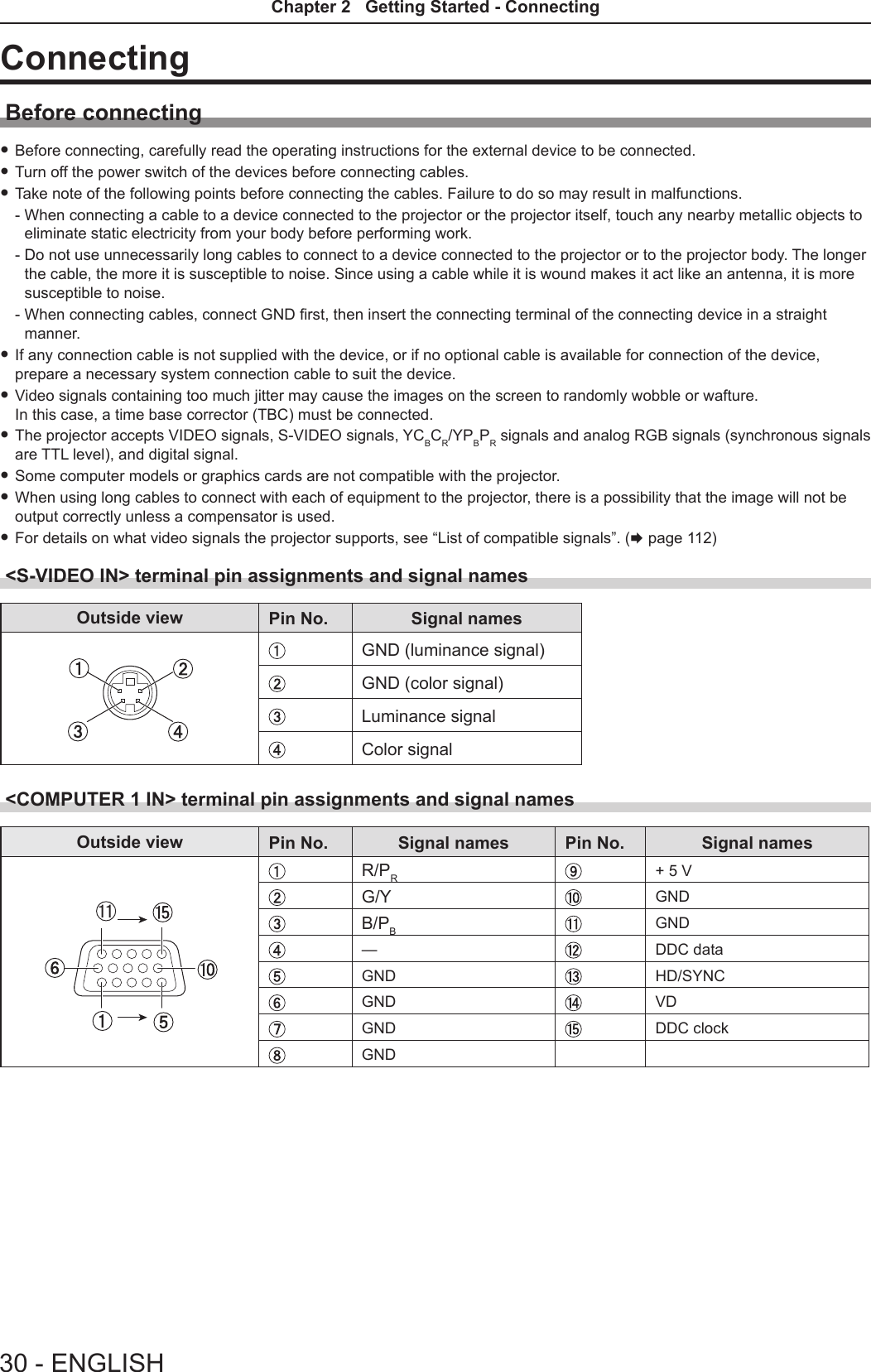
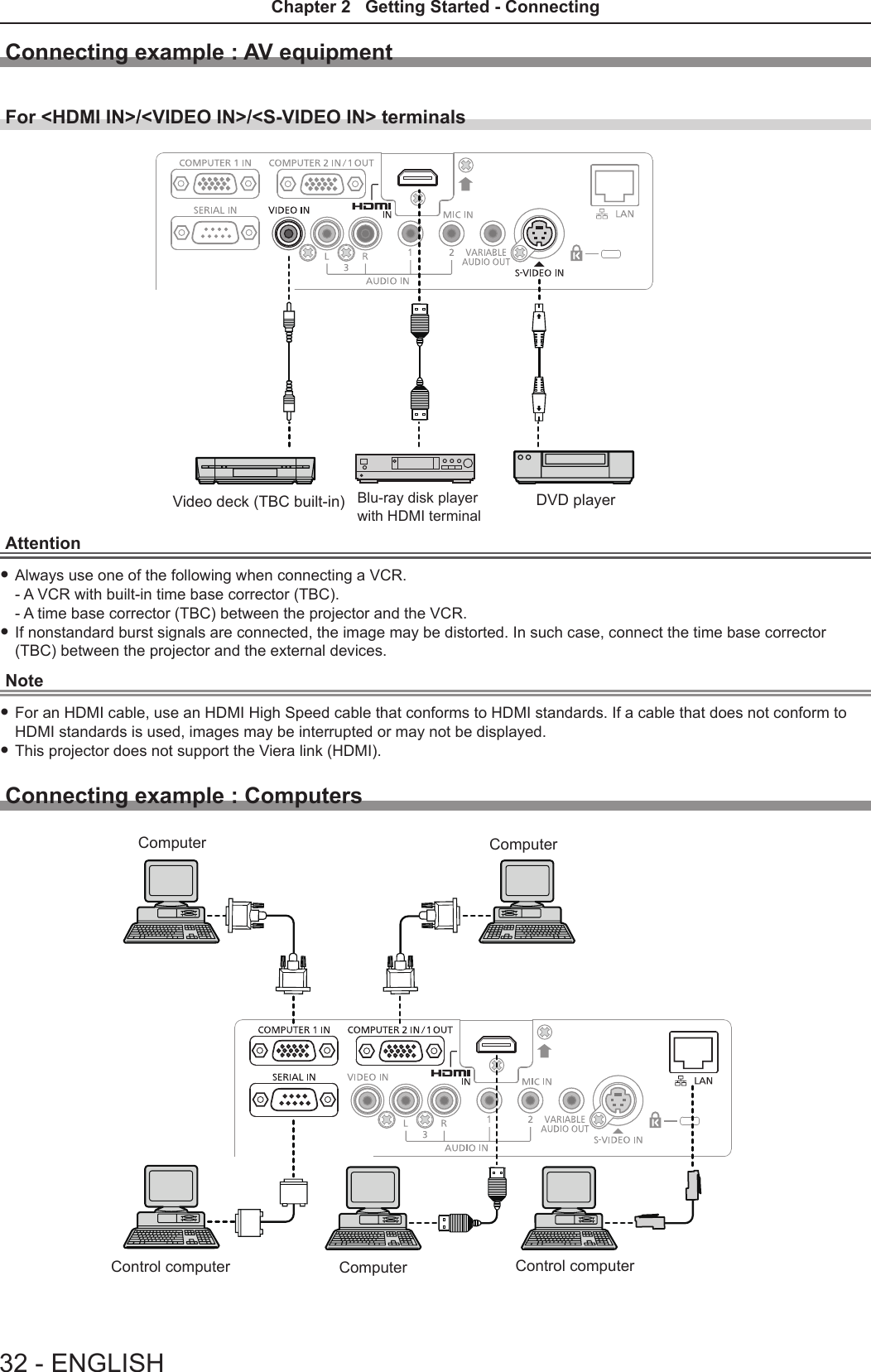
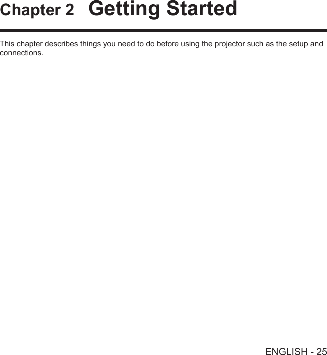
![Attention fWhen connecting the projector to a computer or an external device, use the power cord supplied with each device and commercially available shielded cables.Note fIf you operate the projector using the computer with the resume feature (last memory), you may have to reset the resume feature to operate the projector.Connecting example : AudioNote fIf the [AUDIO IN SELECT] settings are incorrect, the projector may have malfunctions such as the absence of audio. (x page 74) fWhen the <VARIABLE AUDIO OUT> terminal is connected with cable, the sound will not be output from the built-in speaker.ComputerComputerMICComputer Audio equipmentAV equipmentENGLISH - 33Chapter 2 Getting Started - Connecting](https://usermanual.wiki/Panasonic-of-North-America/PT-VW350.PT-VW350-Manual-Part-1-2/User-Guide-2596825-Page-13.png)
![Powering on/offConnecting the power cordMake sure that the supplied power cord is securely xed to the projector body to prevent it from being removed easily.For details of power cord handling, refer to “Read this rst!” (x page 2).Attaching 1) Check the shapes of the <AC IN> terminal on the back of the projector body and the power cord connector and insert the plug completely in the correct direction (until you hear the side tabs click in place).Removing1) Confirm that the projector is in standby mode, and remove the power plug from the outlet.2) Remove the power cord connector from the <AC IN> terminal of the projector body while pressing the side tabs.Power indicatorThe power indicator <ON(G)/STANDBY(R)> informs you the status of the power. Conrm the status of the power indicator <ON(G)/STANDBY(R)> before operating the projector.Indicator status StatusOff The power cord is unplugged.RedLitThe power is switched off (in standby mode). The [PROJECTOR SETUP] menu x [ECO MANAGEMENT] x [STANDBY MODE] is set to [ECO].BlinkingThe power is switched off (in standby mode). The [PROJECTOR SETUP] menu x [ECO MANAGEMENT] x [STANDBY MODE] is set to [NETWORK].*1The power is switched off (in standby mode). The [PROJECTOR SETUP] menu x [ECO MANAGEMENT] x [STANDBY MODE] is set to [NORMAL].*2Orange Lit The projector is cooling down. The power is switched off after a while. (Changes to the standby mode.)Power indicator <ON(G)/STANDBY(R)>ENGLISH - 35Chapter 3 Basic Operations - Powering on/off](https://usermanual.wiki/Panasonic-of-North-America/PT-VW350.PT-VW350-Manual-Part-1-2/User-Guide-2596825-Page-15.png)
![Indicator status StatusGreenLit Projecting.BlinkingThe power is on and the lamp is not working. The [PROJECTOR SETUP] menu x [ECO MANAGEMENT] x [POWER MANAGEMENT] is set to [READY].*3The lamp starts work. The projector will project image after a while.*4*1: The indicator will light as the following order:2.75 seconds (light) → 0.25 seconds (off) → 0.75 seconds (light) → 0.25 seconds (off)*2: The indicator will light as the following order:2.75 seconds (light) → 0.25 seconds (off)*3: The indicator will light as the following order:2.0 seconds (light) → 2.0 seconds (off)*4: The indicator will light as the following order:0.5 seconds (light) → 0.5 seconds (off)1) Connect the power cord to the projector body.2) Connect the power plug to an outlet. fThe power indicator <ON(G)/STANDBY(R)> lights or blinks, and the projector will enter the standby mode.3) Press the power <v/b> button on the control panel or on the remote control. fThe power indicator <ON(G)/STANDBY(R)> lights in green and the image is soon projected on the screen.Attention fBe sure to remove the lens cap before starting projection.Note fIf the [PROJECTOR SETUP] menu → [ECO MANAGEMENT] → [STANDBY MODE] is set to [ECO], it may take approx. 10 seconds longer before the projector starts projecting after the power is turned on, compared with when [NORMAL] is set.When the initial setting screen is displayedWhen the projector is switched on for the rst time after purchase as well as when [INITIALIZE ALL] in the [PROJECTOR SETUP] menu is executed, then the initial setting screen is displayed. Set them in accordance with circumstances. In other occasions, you can change the settings by menu operations.Initial setting (display language)Select the language to show on the screen.After completed the initial setting, you can change the display language from the [LANGUAGE] menu.Powering On the ProjectorBefore switching on the projector, make sure all the other devices are correctly connected (x page 32) and remove the lens cap.3)36 - ENGLISHChapter 3 Basic Operations - Powering on/off](https://usermanual.wiki/Panasonic-of-North-America/PT-VW350.PT-VW350-Manual-Part-1-2/User-Guide-2596825-Page-16.png)
![1) Press asqw to select the display language. 2) Press the <ENTER> button to proceed to the initial setting.Initial setting (installation setting)Set each item. 1) Press as to select an item.Item Description Page[PROJECTION METHOD] Set [PROJECTION METHOD] depending on the installation mode. After completed the initial setting, you can change the setting from the [PRO-JECTOR SETUP] menu → [PROJECTION METHOD].70[SCREEN FORMAT]*1 Set the screen format (aspect ratio) and display position of the image. After completed the initial setting, you can change the settings of each item from the [DISPLAY OPTION] menu → [SCREEN SETTING].64[SCREEN POSITION]*1Set the display position of the image. After completed the initial setting, you can change the settings of each item from the [DISPLAY OPTION] menu → [SCREEN SETTING].64[HIGH ALTITUDE MODE]Change the setting when the projector is used at high altitude. Set it to [OFF] when using the projector at altitude lower than 1 400 m (4 593'), set it to [HIGH1] when using the projector at altitude between 1 400 m (4 593’) and 2 000 m (6 562') above sea level, and set it to [HIGH2] when using the projector at altitude between 2 000 m (6 562’) and 2 700 m (8 858') above sea level.70*1 Only for PT-VW350.2) Press qw to switch the setting.3) Press the <ENTER> button to perform next initial setting.PT-VX420PT-VW350ENGLISH - 37Chapter 3 Basic Operations - Powering on/off](https://usermanual.wiki/Panasonic-of-North-America/PT-VW350.PT-VW350-Manual-Part-1-2/User-Guide-2596825-Page-17.png)
![Initial setting (standby mode)Item Description Page[STANDBY MODE] Set the operation mode during standby. f The default setting is [ECO] that keeps power consumption low during standby. f Set to [NORMAL] to use the network function or the serial communication function during standby. f Set to [NETWORK] to reduce power consumption during standby, and to operate the projector via the wired LAN or the serial communication function by using the Wake on LAN function.After completed the initial setting, you can change the setting from the [PRO-JECTOR SETUP] menu → [ECO MANAGEMENT] → [STANDBY MODE].721) Press qw to switch the setting.2) Press the <ENTER> button. fConrm the setting value and complete the initial setting.Note fIf you press the <RETURN> button while the initial setting screen is displayed, you can go back to the previous screen. fThe above initial setting screen is the one displayed when the projector is switched on for the rst time after purchase. When [PROJECTOR SETUP] menu → [INITIALIZE ALL] is executed, the setting of [STANDBY MODE] before execution is displayed.Making adjustments and selectionsIt is recommended that images are projected continuously for at least 30 minutes before the focus is adjusted.1) Adjust the focus of the image roughly. (x page 40)2) Change the settings of the [PROJECTOR SETUP] menu → [PROJECTION METHOD] depending on the installation mode. (x page 70) fRefer to “Navigating through the menu” (x page 47) for the operation of the menu screen.3) Press the <INPUT SELECT> button on the control panel or the input selection (<COMPUTER 1>, <COMPUTER 2>, <HDMI>, <VIDEO>, <S-VIDEO>) buttons on the remote control to select the input signal.4) Adjust the front, back and sideway tilt of the projector with the adjustable feet. (x page 29)5) If the input signal is an analog RGB signal, press the <AUTO SETUP> button.38 - ENGLISHChapter 3 Basic Operations - Powering on/off](https://usermanual.wiki/Panasonic-of-North-America/PT-VW350.PT-VW350-Manual-Part-1-2/User-Guide-2596825-Page-18.png)
![6) Adjust the size of the image to match the screen with the zoom ring.7) Adjust the focus with the focus ring.Note fWhen the projector is switched on for the rst time after purchase as well as when the [PROJECTOR SETUP] menu → [INITIALIZE ALL] is executed, the initial setting screen is displayed after projection starts.Powering Off the Projector1) Press the power <v/b> button on the control panel or on the remote control. fThe following message appears.2) Press qw to select [OK], and press the <ENTER> button. (Or press the power <v/b> button on the control panel or on the remote control again.) fProjection of the image will stop, and the power indicator <ON(G)/STANDBY(R)> lights in orange. (The fans keep running.)3) Wait until the power indicator <ON(G)/STANDBY(R)> lights or blinks in red. fThe projector enters standby mode when the power indicator <ON(G)/STANDBY(R)> lights or blinks in red.Note fWhile the power indicator <ON(G)/STANDBY(R)> is lighting in orange, the lamp is being cooled down and the projector cannot be turned on. Wait until the power indicator <ON(G)/STANDBY(R)> starts lighting or blinking in red to turn on the projector again. fWhen packing the projector for transportation and storage, please make sure that each indicator is off.Direct Power Off functionYou can disconnect the power cord from the wall outlet or turn off the power breaker switch even during projection.Attention fDo not disconnect the power cord from the wall outlet or turn off the power breaker switch in a short time (about 1 minute) after the lamp is lit. Doing so may cause the lamp fail to light while you powering on the projector next time, or result in premature deterioration of the lamp.Note fWhen using the Direct Power Off function, you cannot restart the projector immediately after disconnecting the power cord from the wall outlet or turning off the power breaker switch. The lamp remains high temperature and needs to cool down, so it sometimes takes a longer time than usual for the lamp to light up again. ENGLISH - 39Chapter 3 Basic Operations - Powering on/off](https://usermanual.wiki/Panasonic-of-North-America/PT-VW350.PT-VW350-Manual-Part-1-2/User-Guide-2596825-Page-19.png)
![ProjectingCheck the connections of the peripheral devices (x page 30) and connection of the power cord (x page 34) and switch on the power (x page 36) to start the projector. Select the image and adjust the state of the image.Selecting the input signalSelect an input signal.1) Press the <COMPUTER 1>, <COMPUTER 2>, <HDMI>, <VIDEO> or <S-VIDEO> button on the remote control or <INPUT SELECT> button on the control panel. fThe image of the signal being input in the selected terminal is projected. fYou can check the input source through [DETAILED] / [SIMPLE] under the [DISPLAY OPTION] → [ON-SCREEN DISPLAY] → [INPUT GUIDE] menu. fYou can also select the input source by pressing asqw on the [DETAILED] screen.Attention fImages may not be projected properly depending on the connected device and DVD, video tape, etc. to be played. Set the [PICTURE] menu → [RGB/YCBCR] or [RGB/YPBPR] (x page 55). fCheck the aspect ratio of the screen and the image and select the optimum aspect ratio under the [POSITION] menu (x page 59).How to adjust the state of the imageIf the projected image or the position is not correct when the positioning of the projector and the screen is correctly installed, adjust the focus and zoom.1) Adjust the projection angle. fInstall the projector on a at surface and parallel to the screen so that the projected screen is rectangular. fIf the screen is tilted downward, extend the adjustable feet and adjust the projection screen so that the projected screen is rectangular. fFor details, see “Adjusting adjustable feet” (x page 29).2) Adjust the zoom and the focus. fRotate the zoom ring to zoom in and out the image. fRotate the focus ring to adjust the focus of the projected image. Note fIt is recommended that the images are projected continuously for at least 30 minutes before the focus is adjusted. fIf you adjust the focus, you may need to adjust the size of the image by turning the zoom ring again. fIf keystone distortion occurs, see the [POSITION] menu → [KEYSTONE] (x page 56).[DETAILED] input guide [SIMPLE] input guideFocus ringZoom ringIf there is no signal input ([COMPUTER1], [COMPUTER2] or [HDMI]), this screen will be displayed. Check the output settings of your computer.40 - ENGLISHChapter 3 Basic Operations - Projecting](https://usermanual.wiki/Panasonic-of-North-America/PT-VW350.PT-VW350-Manual-Part-1-2/User-Guide-2596825-Page-20.png)