Proxim Wireless MP11R-ABG MP.11x Outdoor Wireless Ethernet System User Manual Part I
Proxim Wireless Corporation MP.11x Outdoor Wireless Ethernet System Users Manual Part I
UserManual.wiki
>
Proxim Wireless
>
MP11R-ABG User Manual
>
Users Manual Part I
Contents
1.
Users Manual Part I
2.
Users Manual Part II
3.
Professional Installation Guide
4.
Regulatory Flyer
5.
manual 1
6.
manual 2
Users Manual Part I
Navigation menu
Upload a User Manual
Namespaces
Wiki Guide
HTML
PDF
Info
Views
User Manual
Discussion / Help
Navigation


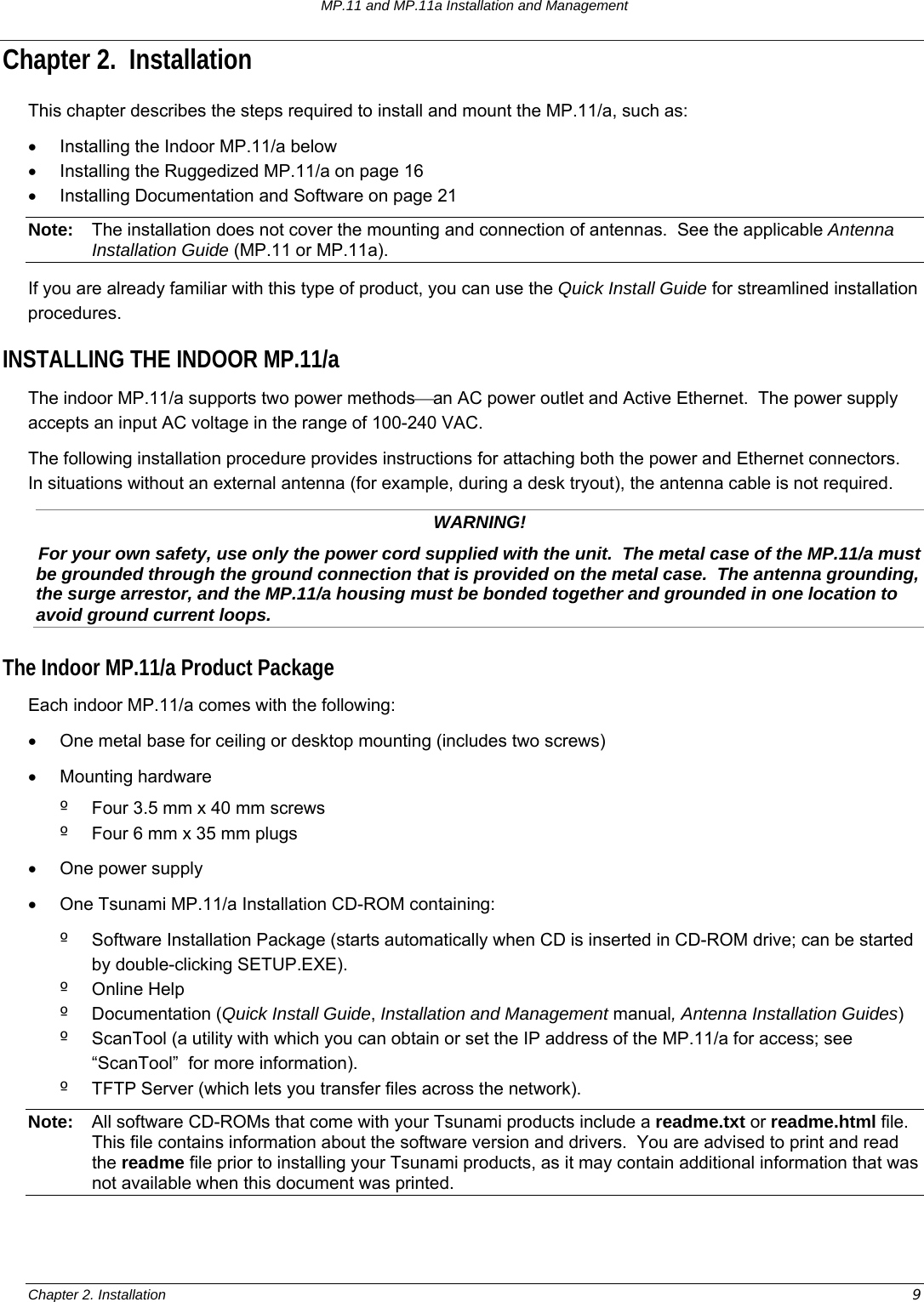

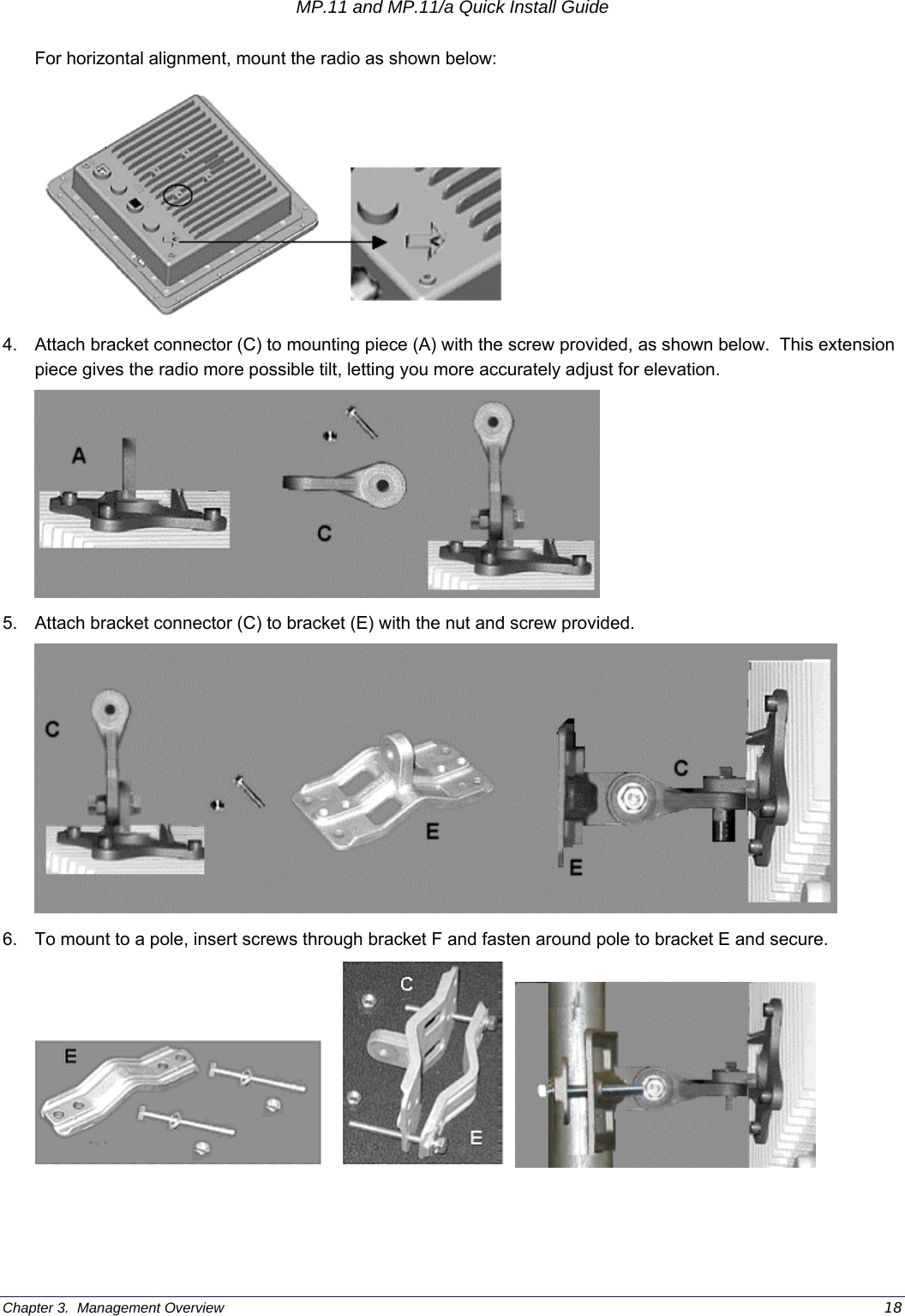
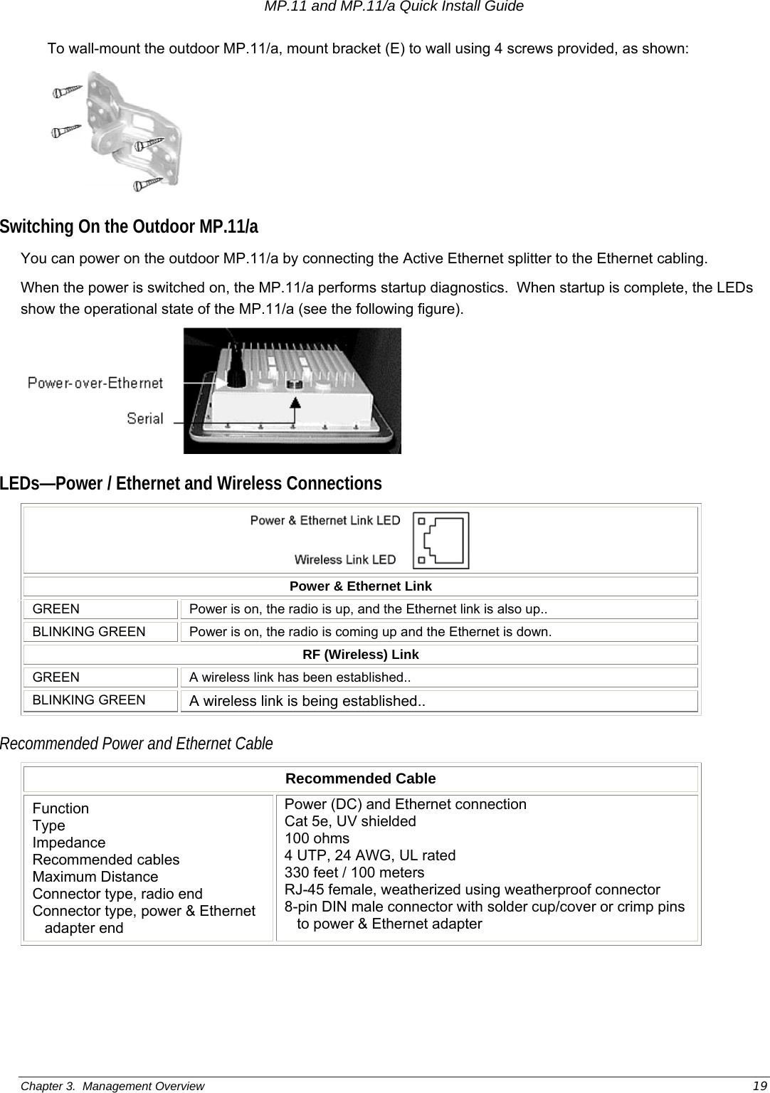
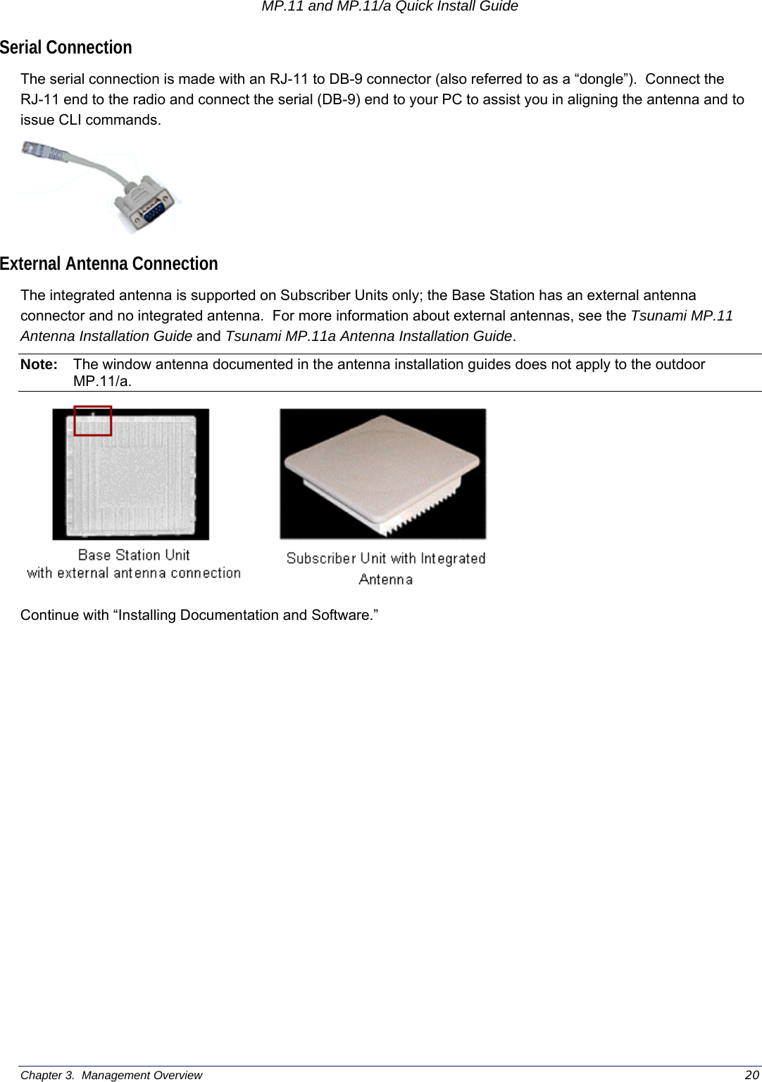
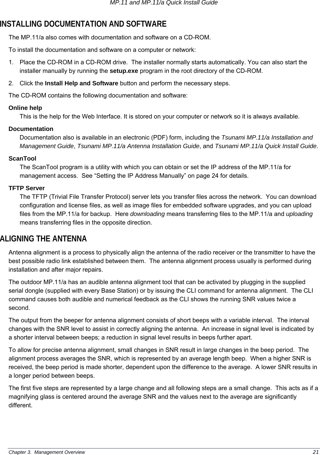
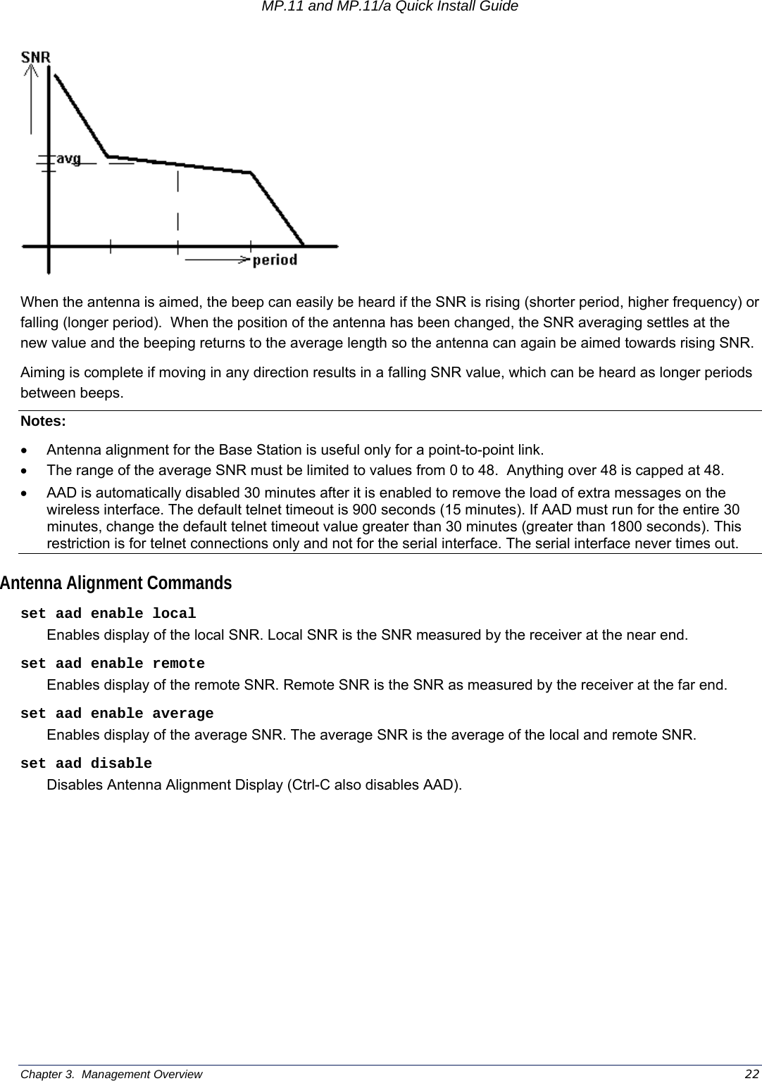
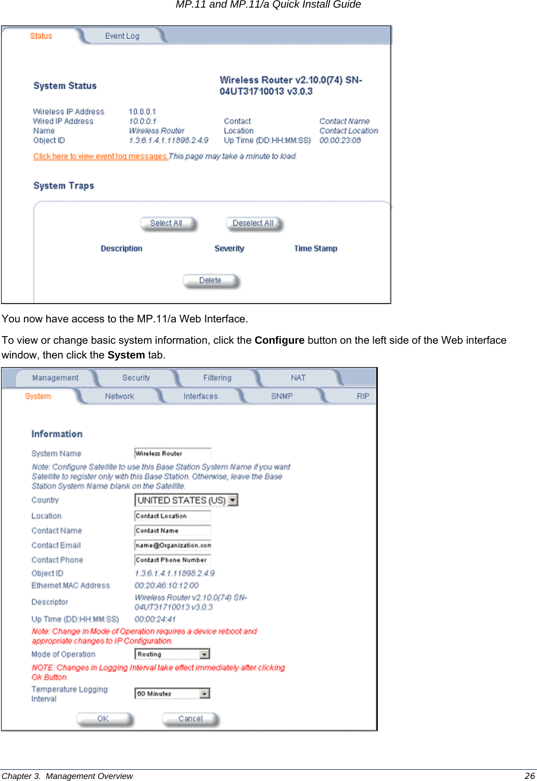
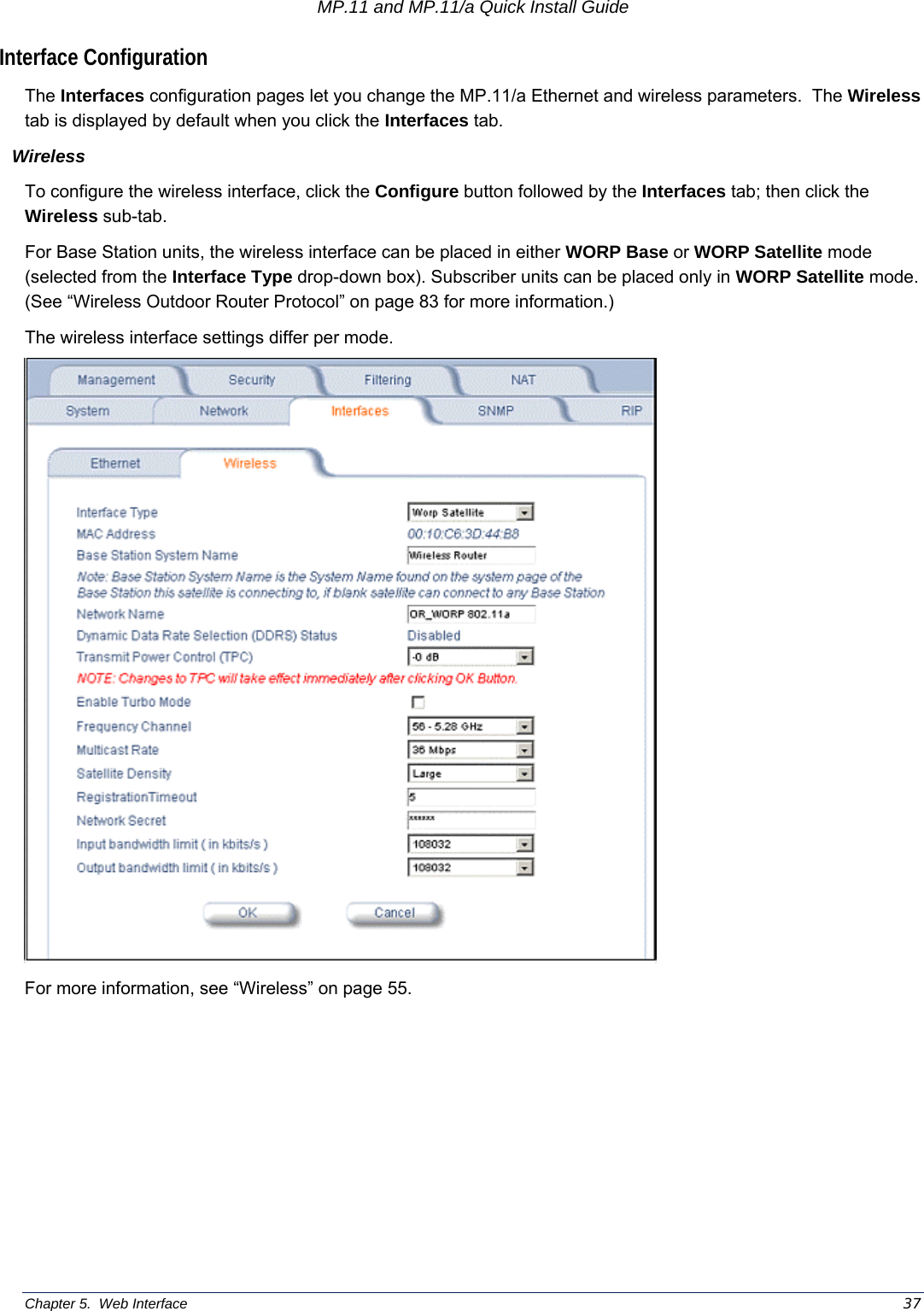
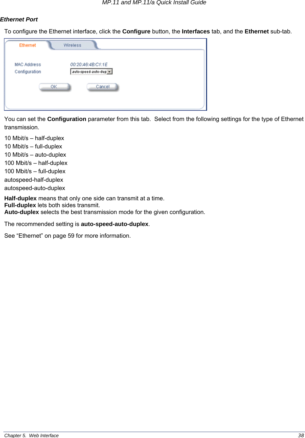
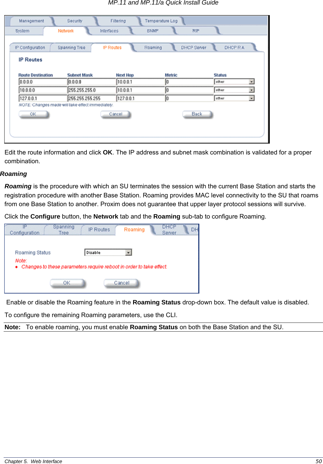
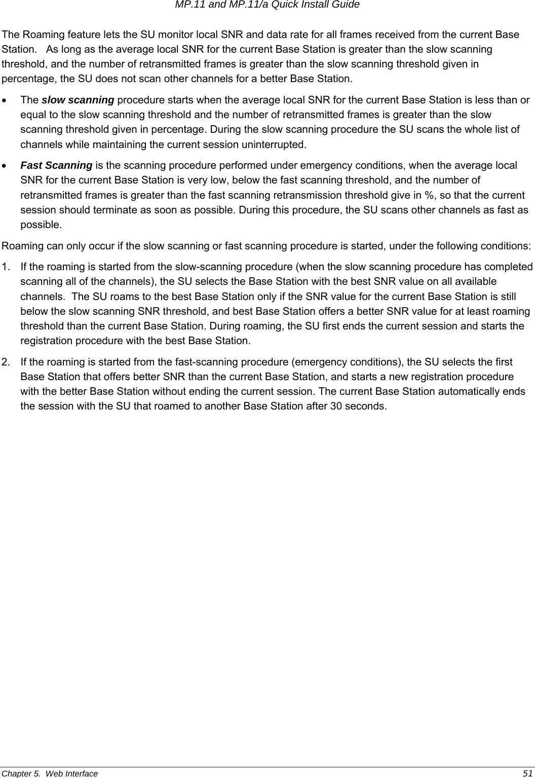
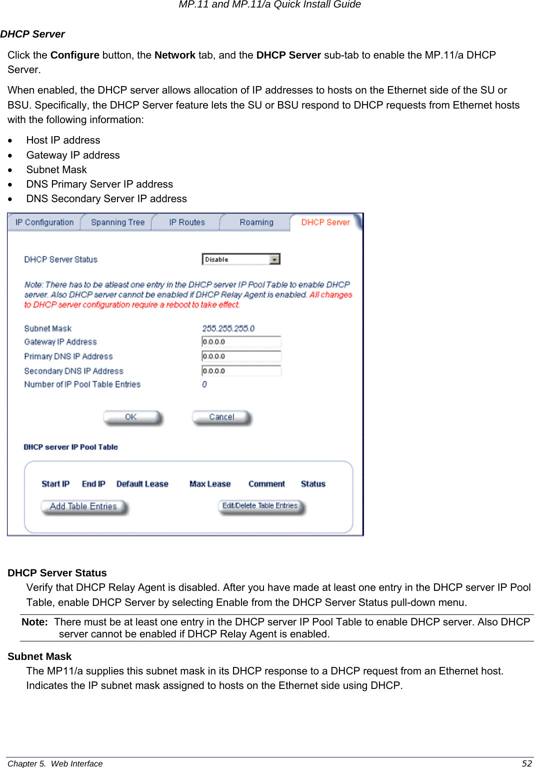
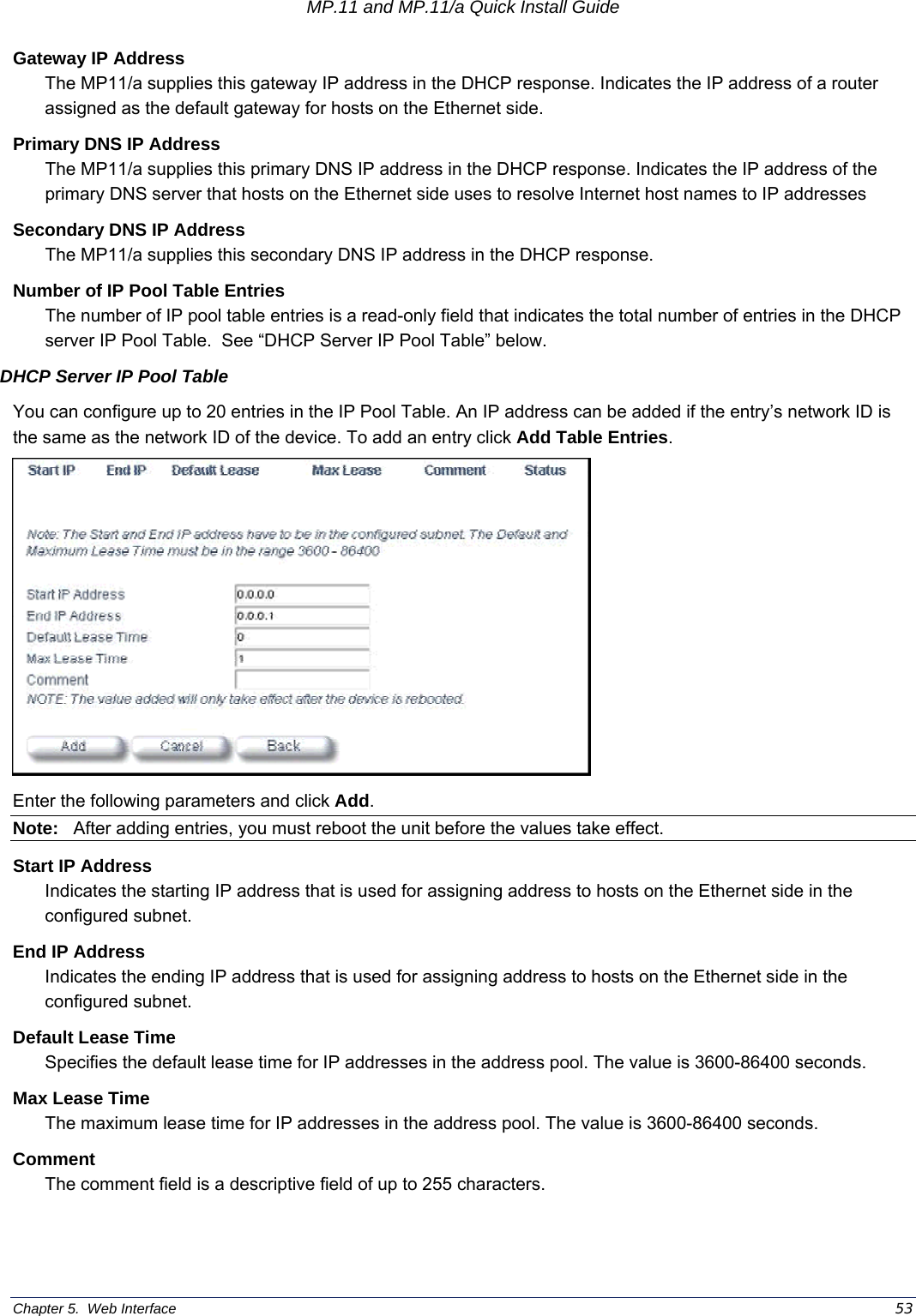

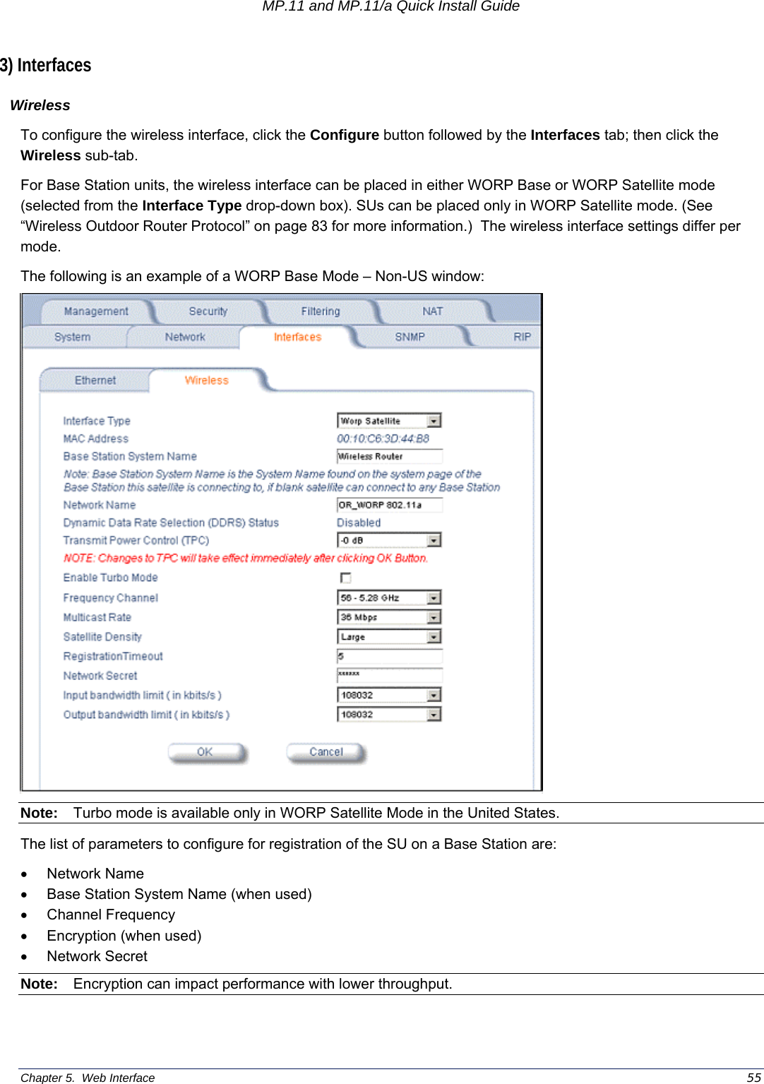
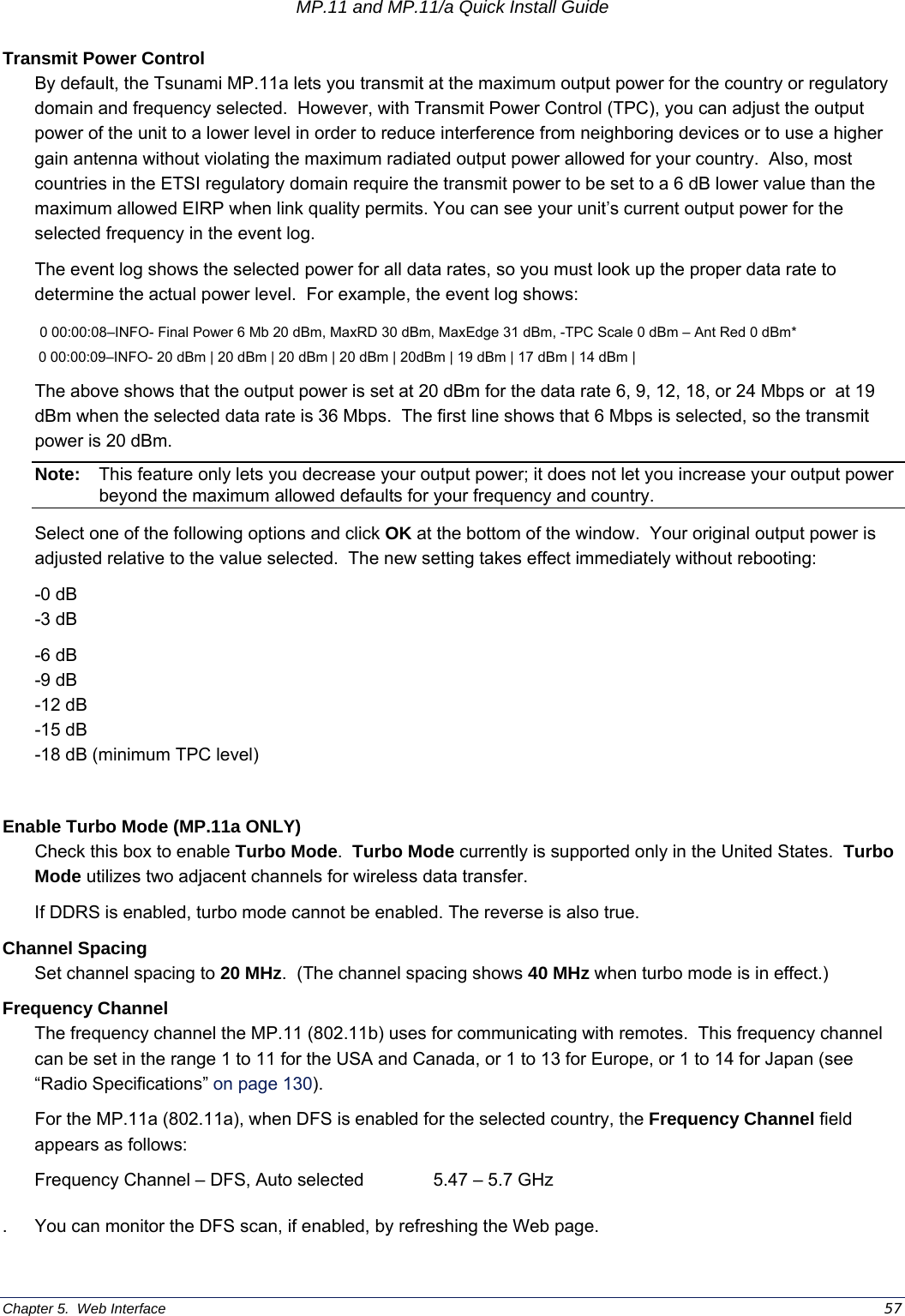
![MP.11 and MP.11/a Quick Install Guide Chapter 5. Web Interface 56 You can change the following parameters: Interface Type The interface type can be Worp Satellite or Worp Base. *See “Wireless Outdoor Router Protocol” on page 83.) Base Station System Name The name found on the system page of the Base Station to which this SU is connecting. This parameter can be used as an added security measure, and when there are multiple Base Stations in the network and you want an SU to register with only one when it may actually have adequate signal strength for either. If the Base Station System Name is left blank on the SU, it can register with any Base Station with a matching Network Name and Network Secret. Network Name A Network Name is name given to a network so that multiple networks can reuse the same frequency without problems. An SU can only register to a base if it has the same Network Name. The Network Name is one of the parameters that allow a Subscriber Unit to register on a Base Station. The Base Station System Name and Frequency Channel also are parameters to guide the SU to the proper Base Station on the network, but they provide no security. Basic security is provided through encryption, as it causes none of the messages to be sent in the clear. Further security is provided by mutual authentication of the Base Station and Subscriber Unit using the Network Secret. Dynamic Data Rate Selection (DDRS) Status (Tsunami MP.11/a only) The WORP Dynamic Data Rate Selection (DDRS) lets the Base Station and SUs monitor the remote average signal-to-noise ratio (SNR) and to adjust the data rate to an optimal value (to provide best possible throughput) according to the current communication conditions during run-time. Each frame received in the WORP protocol reports the signal and noise level in dBm at which the sender received the previous frame from the receiver, and provides the values to calculate the signal to noise ratio (SNR) in dB. SNR is calculated then averaged: SNR [dB] = signal level [dBm] – noise level [dBm] This information lets the sender adjust the transmission data rate to the optimal level to provide the best possible throughput. When you enable or disable WORP DDRS on the Base Station, the Base Station sends an announcement to SUs and the SUs enable or disable WORP DDRS automatically. Note: DDRS threshold values must be configured in the Base Station and SUs separately. Both the Base Station and the SU monitors the remote SNR. The Base Station monitors and calculates the average remote SNR for each SU that is registered. An SU monitors and calculates the average remote SNR for the Base Station. The DDRS Status is configurable only for the WORP Base Mode. For WORP Base Mode, select the DDRS Status “Enable” or “Disable” from the drop-down box provided. For the WORP Satellite Mode, DDRS Status is read-only parameter and its value is based upon the WORP Base to which this SU is associated. WORP DDRS is not supported in Turbo Mode.](https://usermanual.wiki/Proxim-Wireless/MP11R-ABG.Users-Manual-Part-I/User-Guide-474706-Page-56.png)