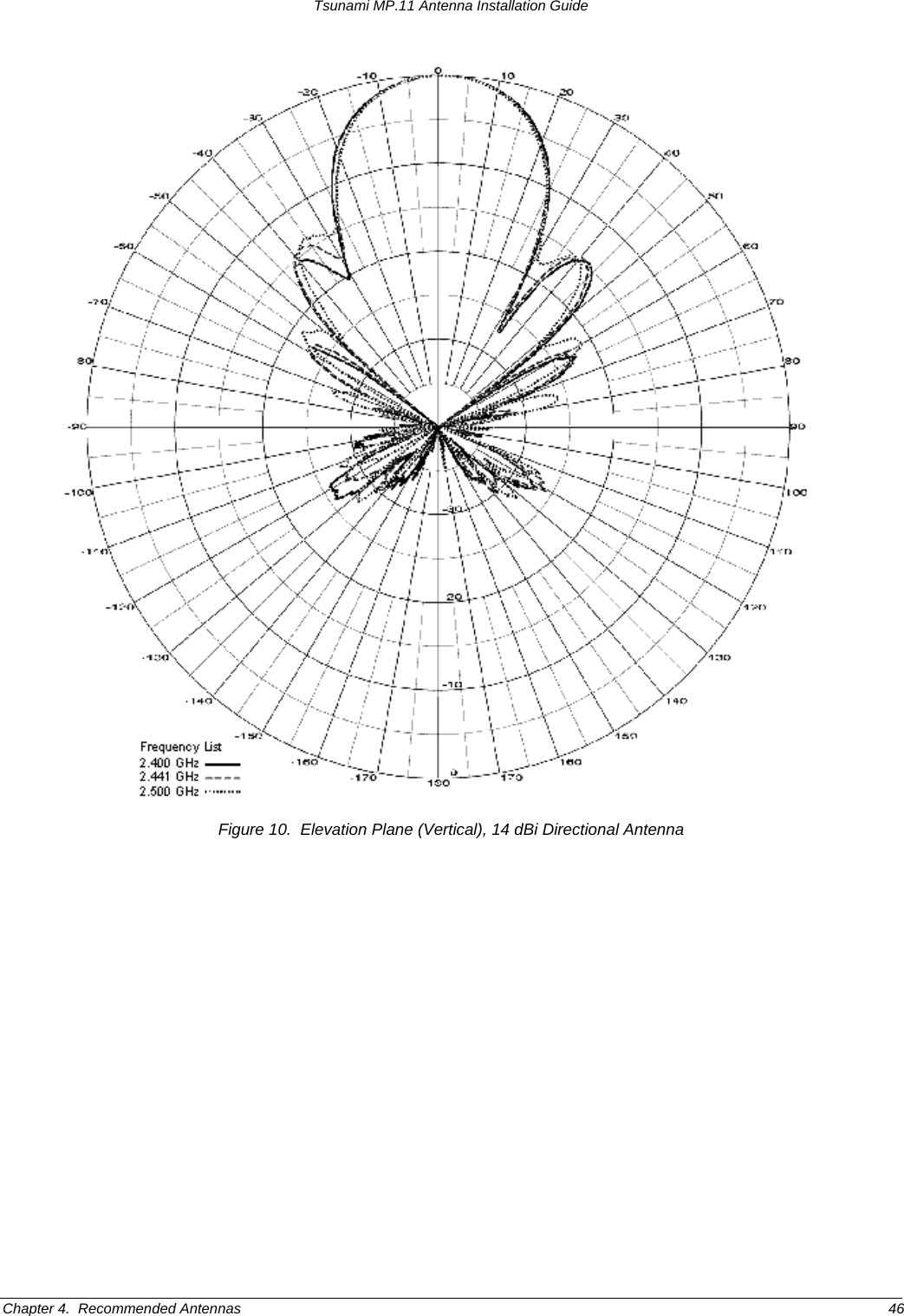
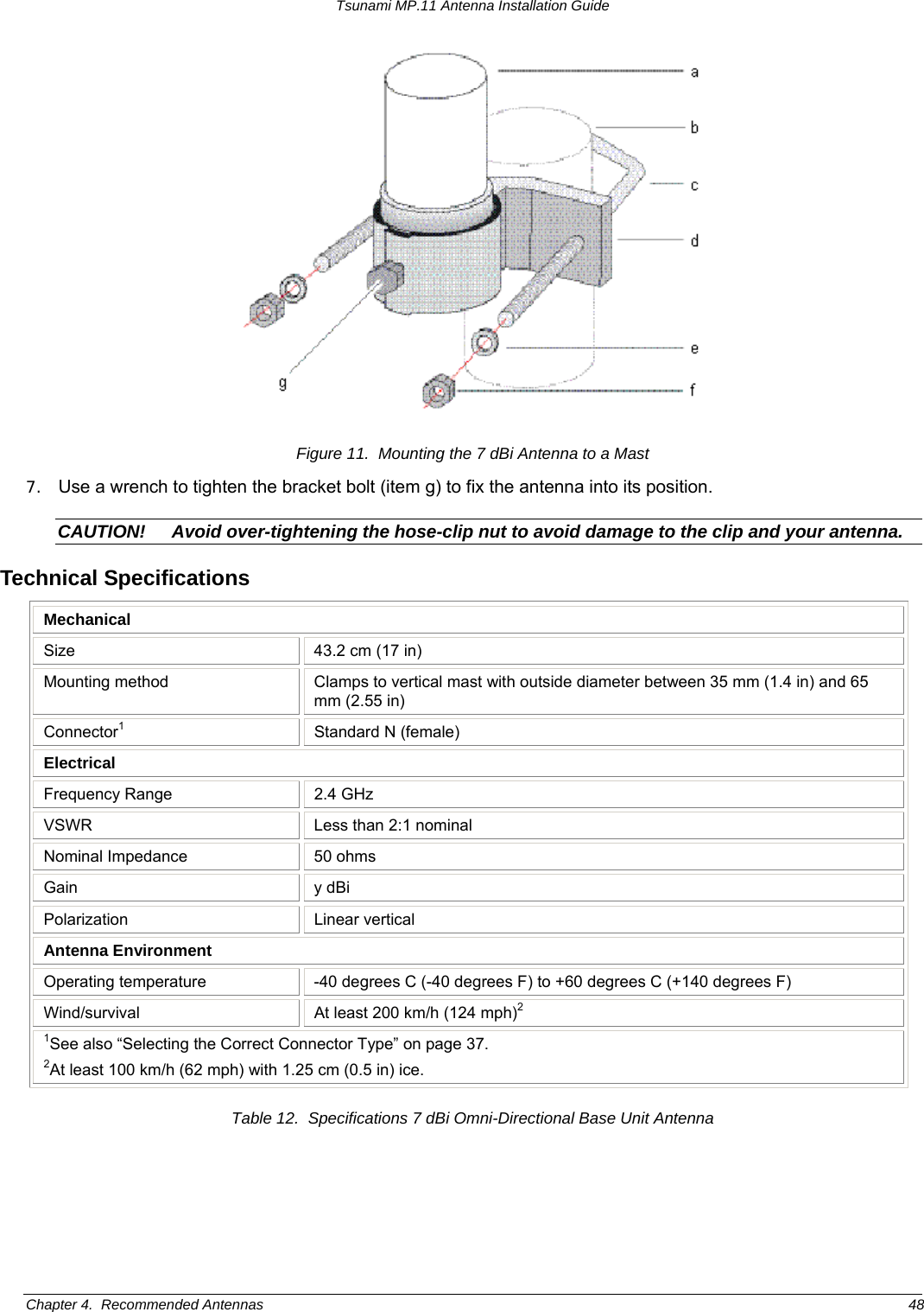
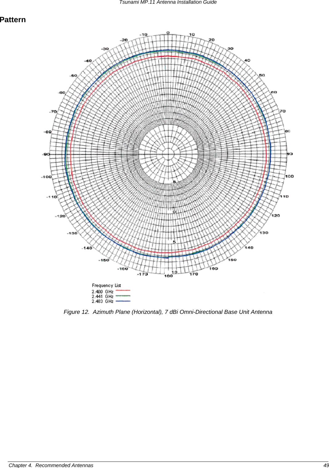
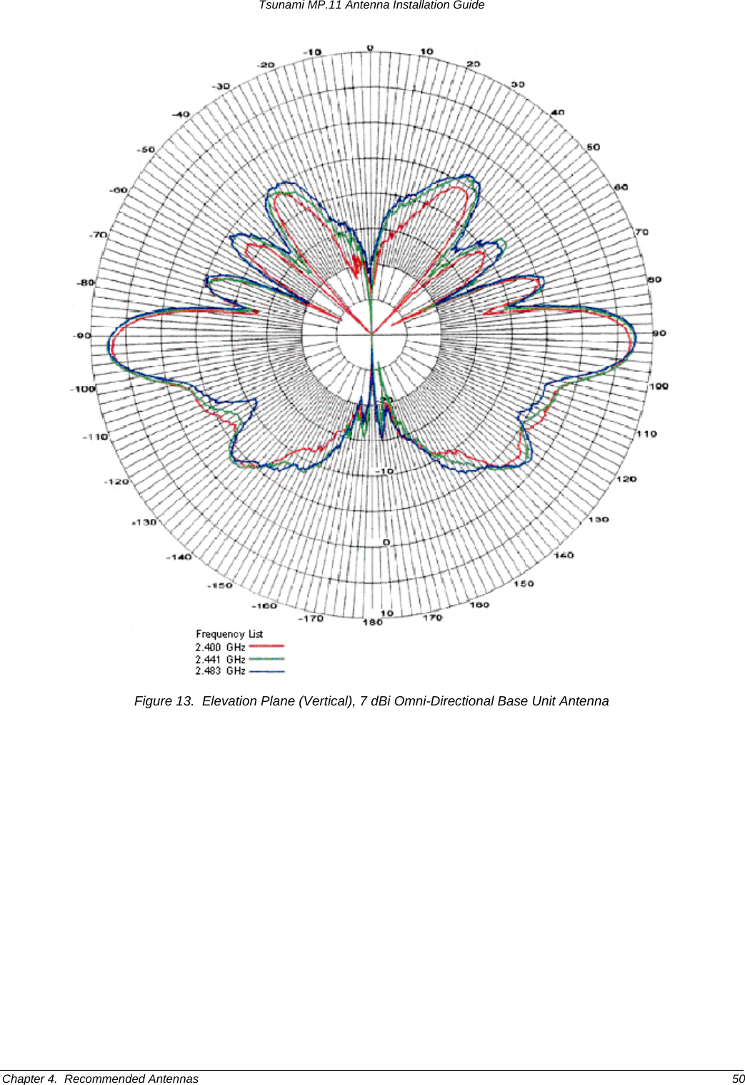
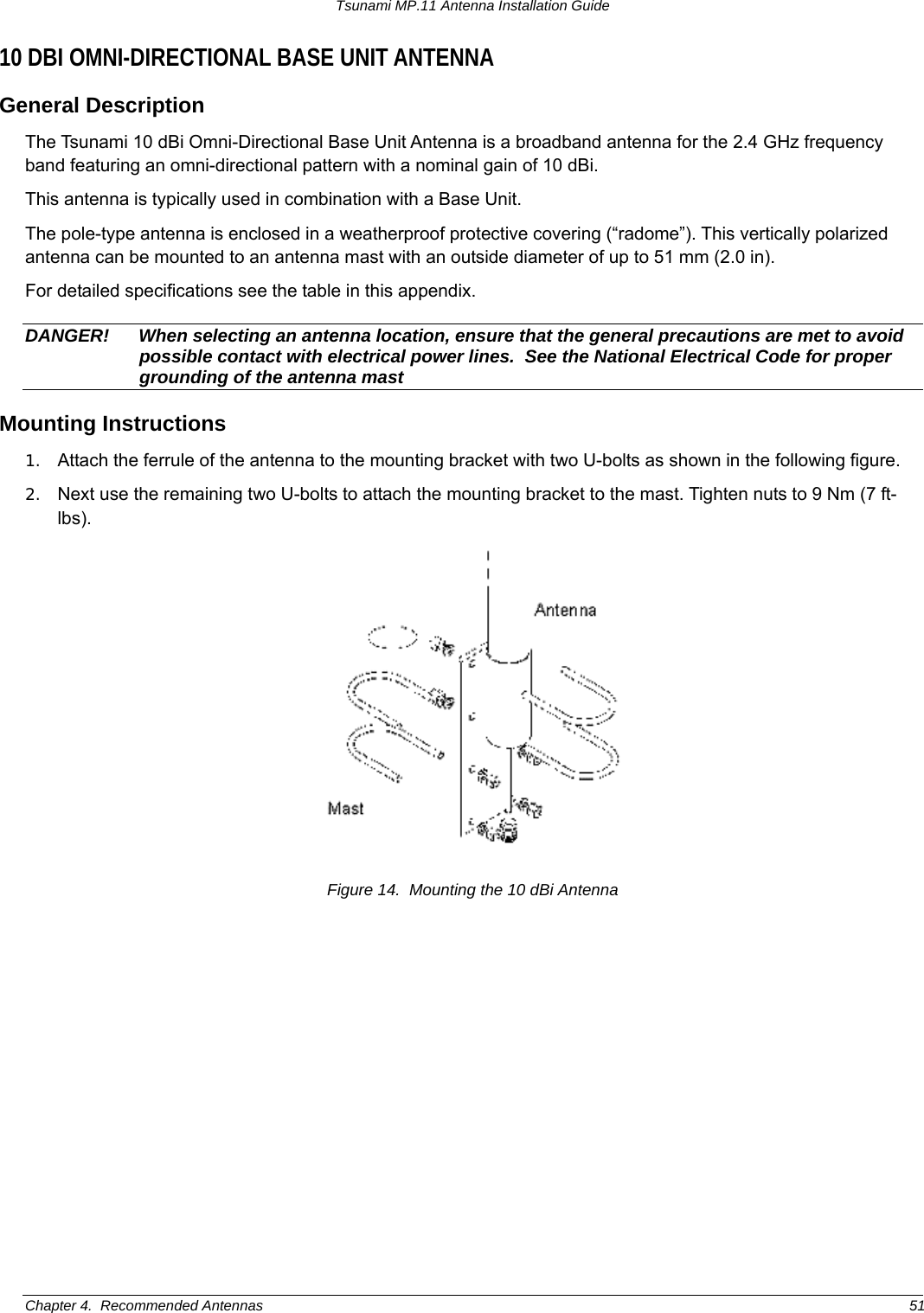
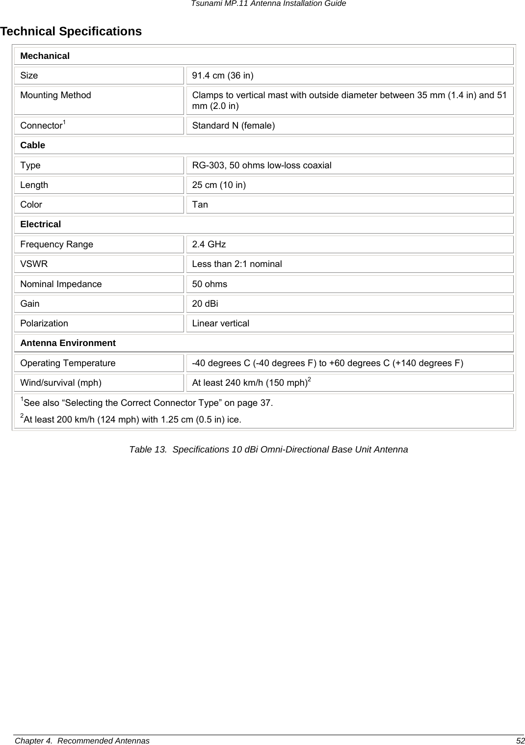
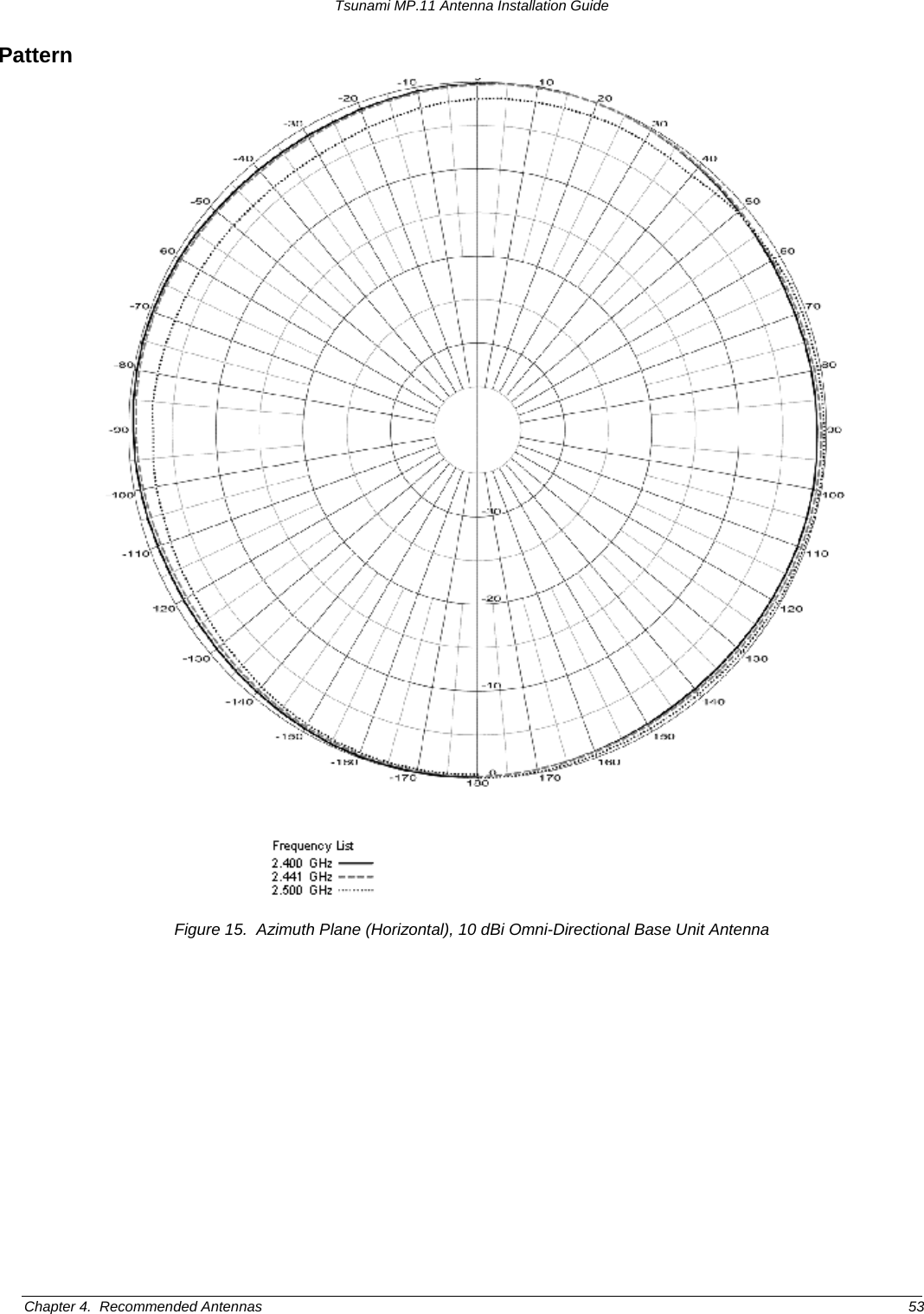
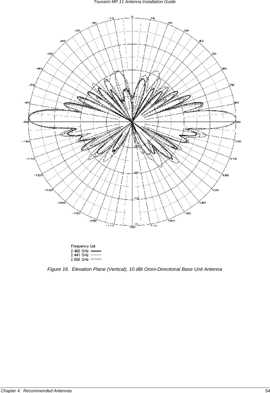
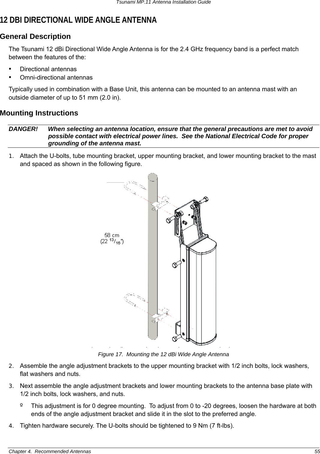
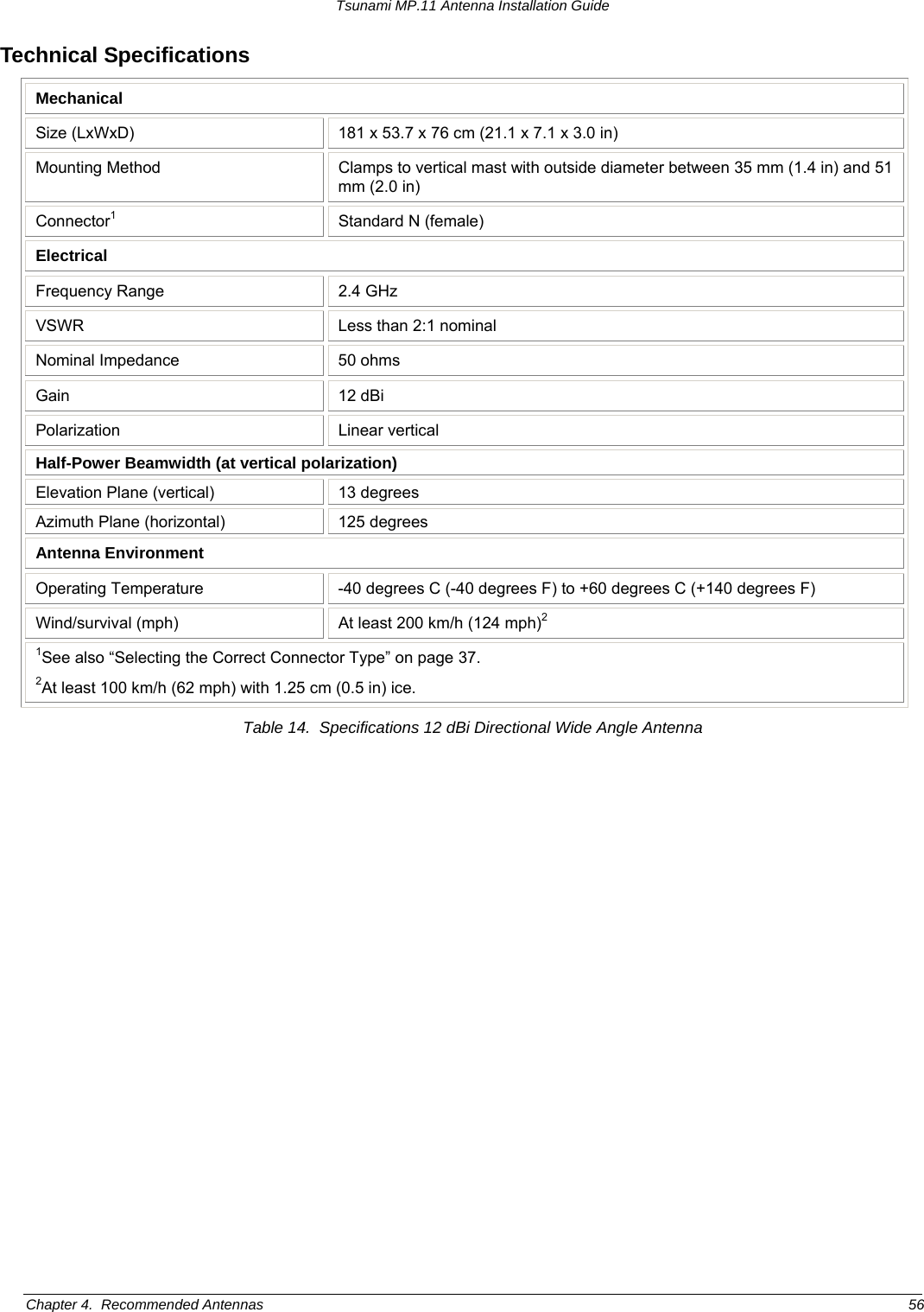
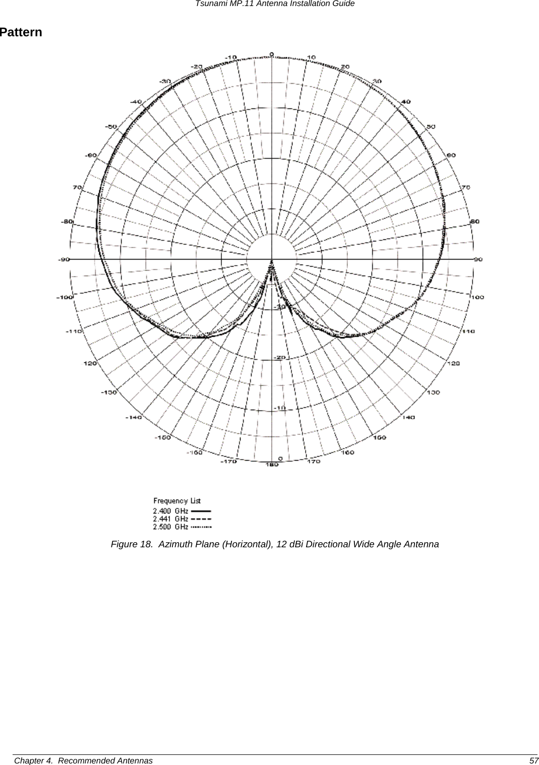
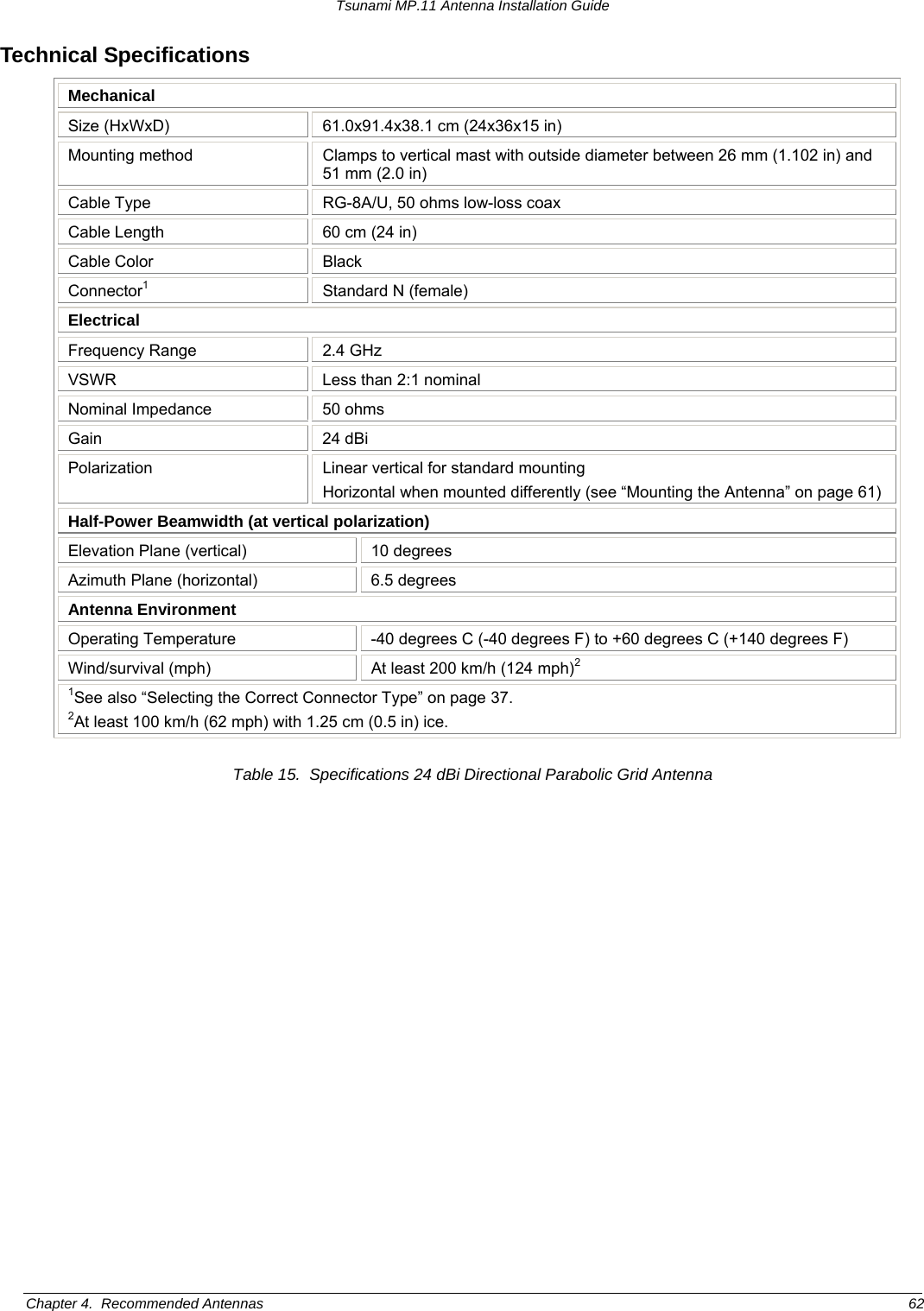
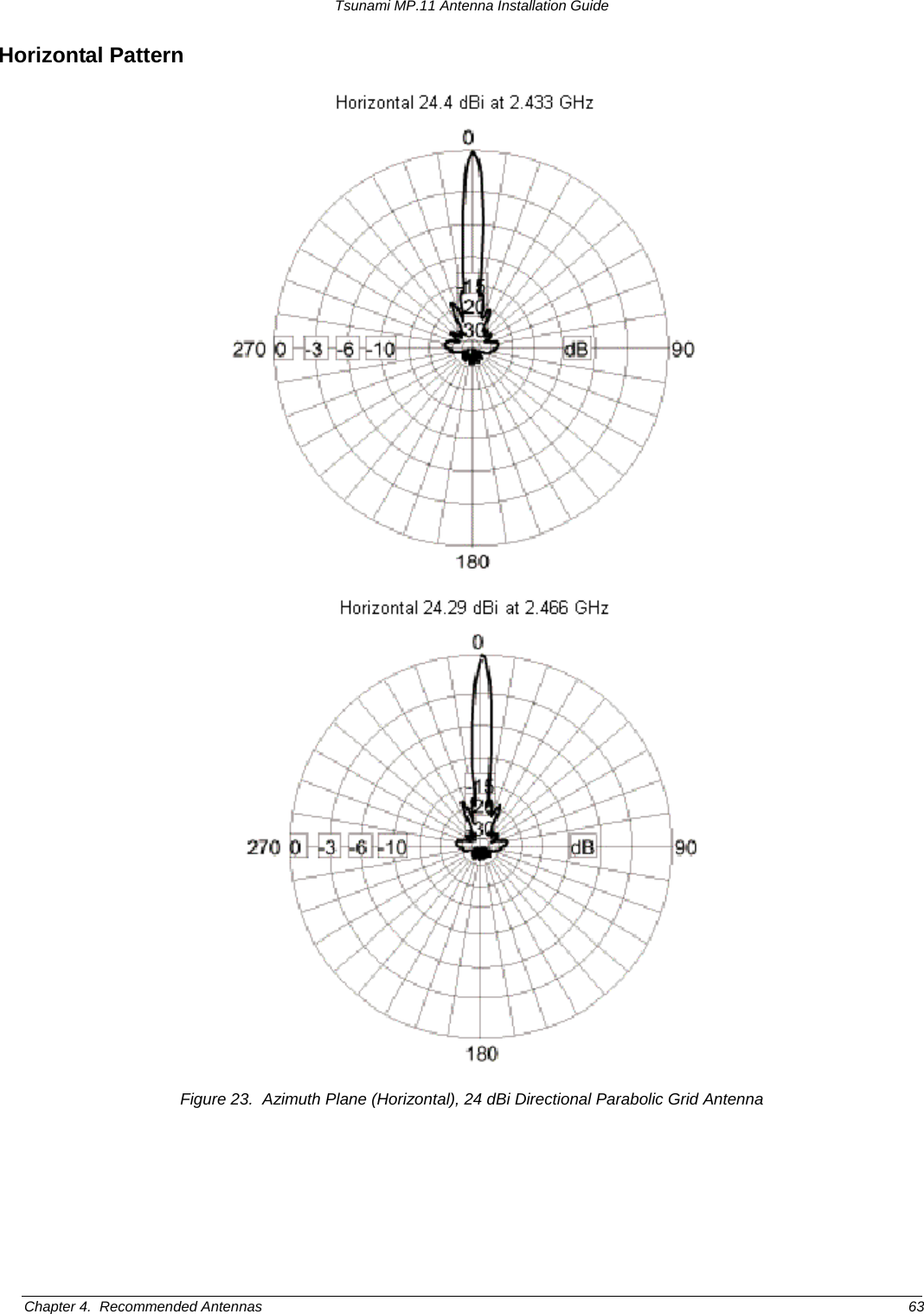
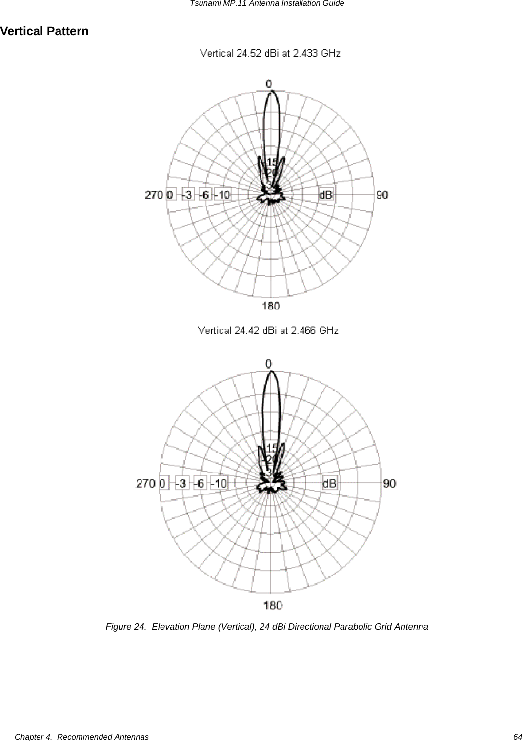
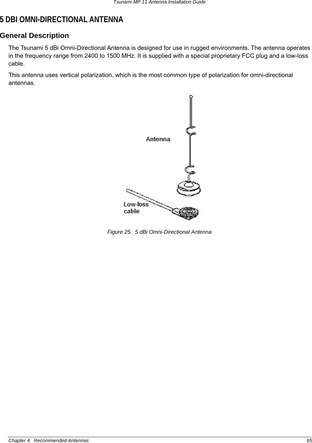
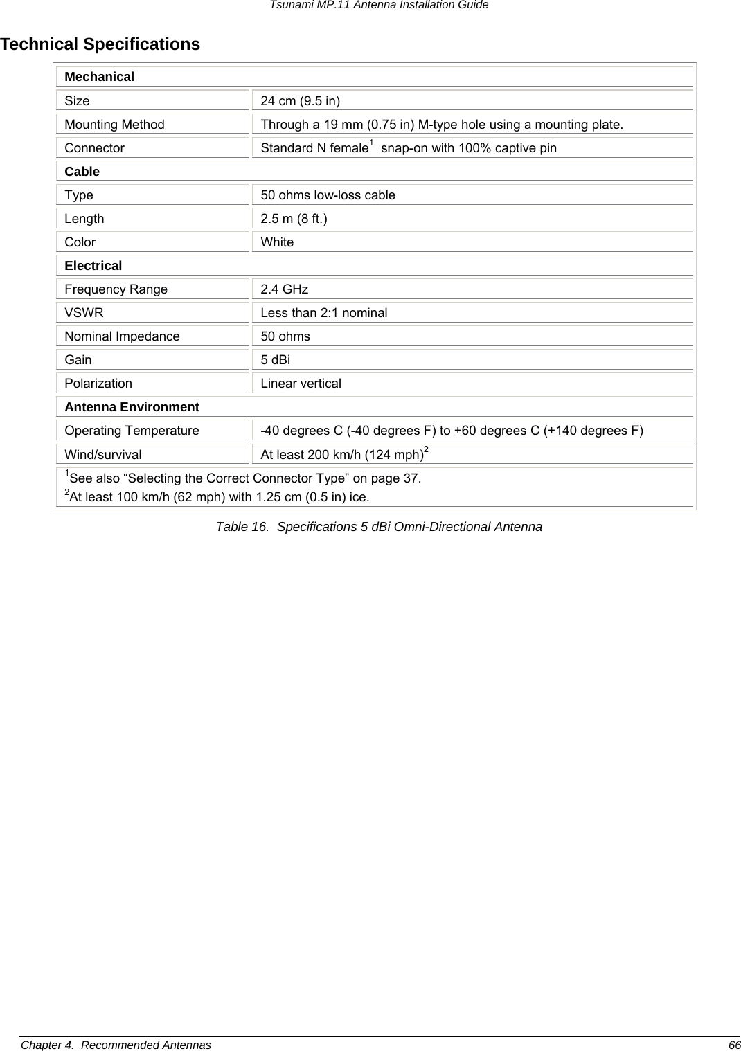
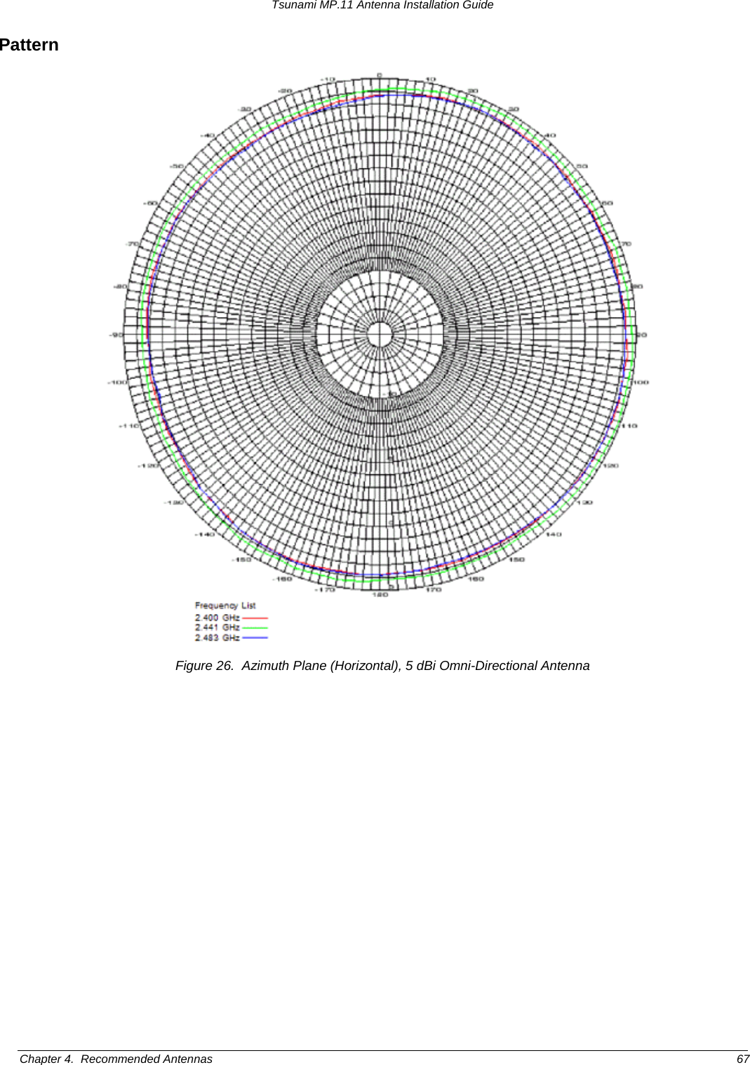
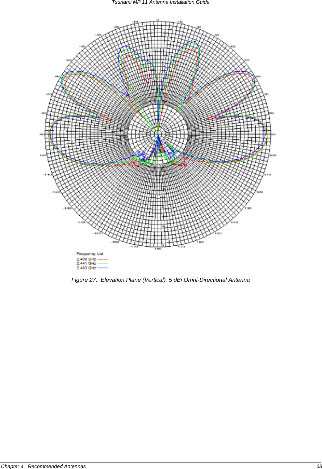
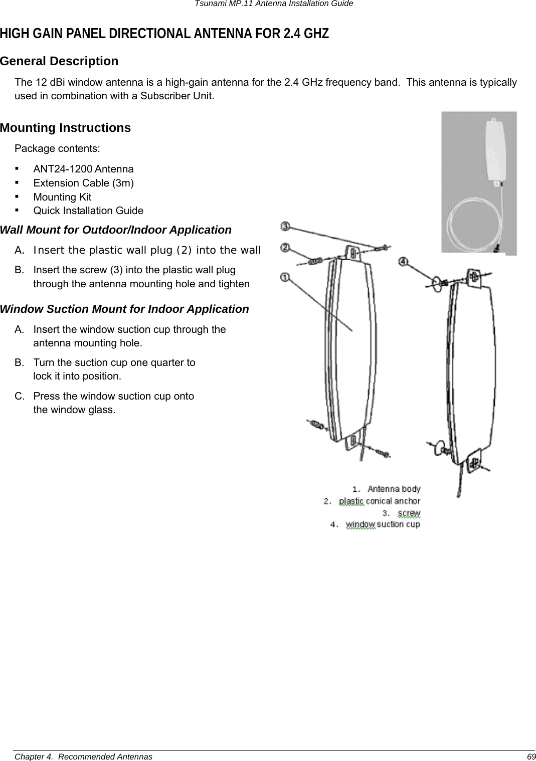
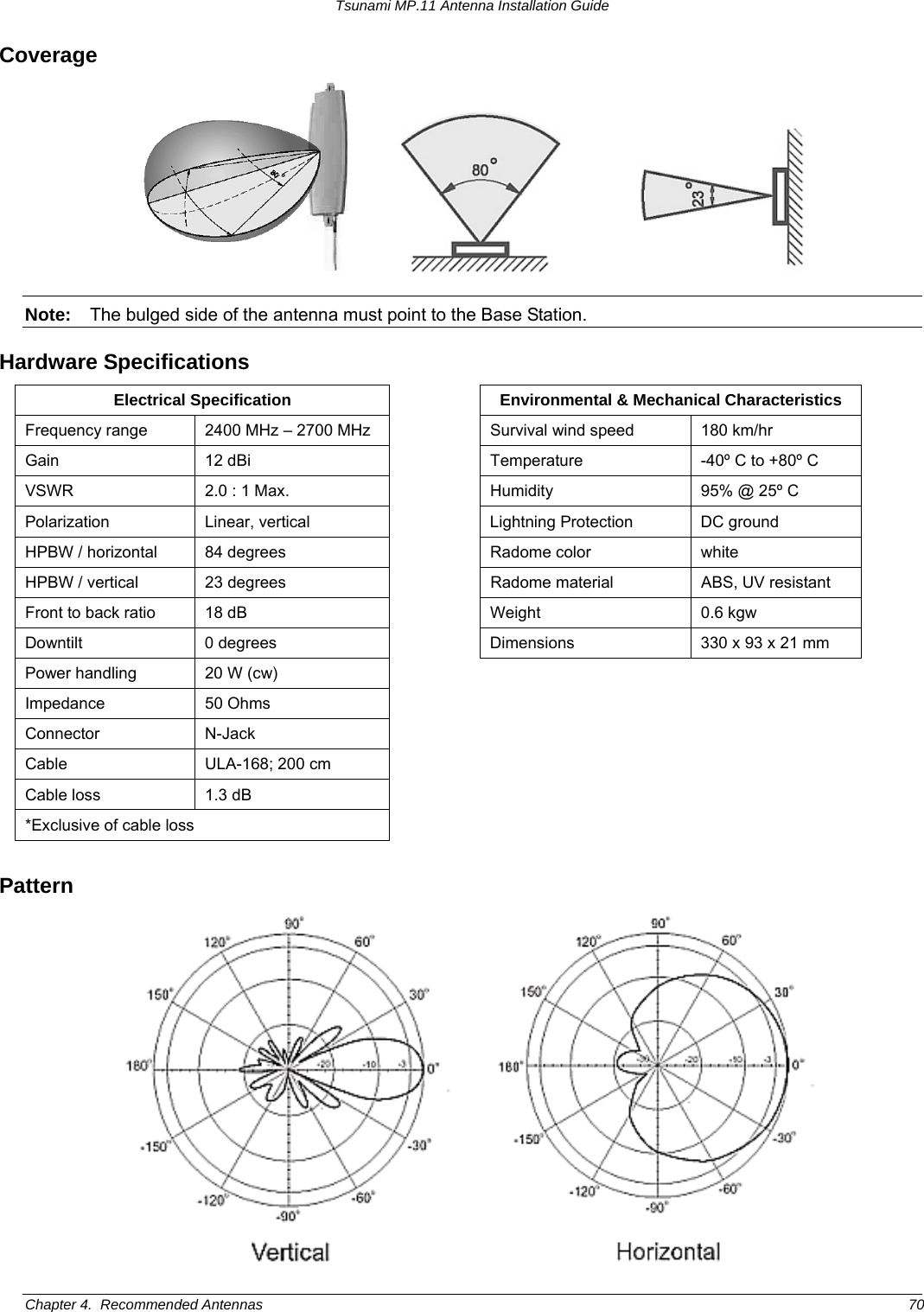
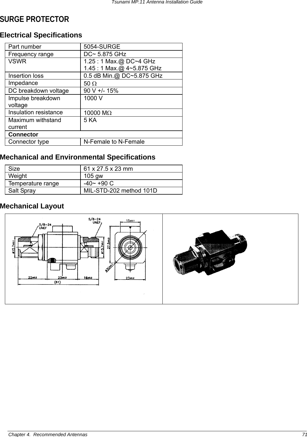
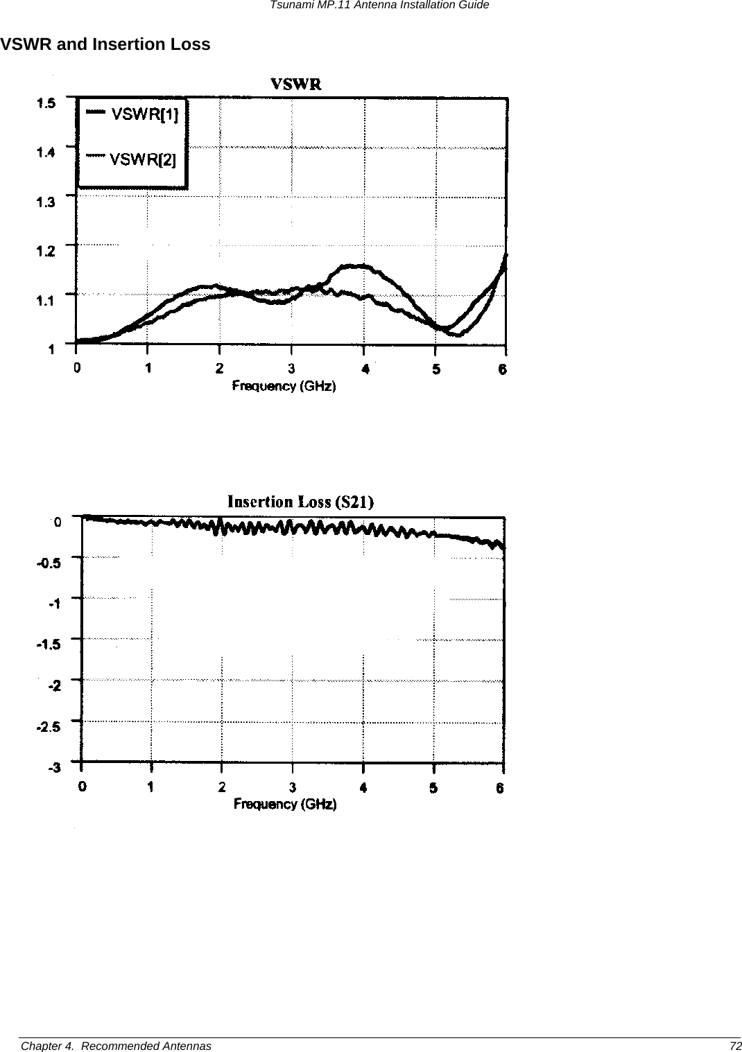
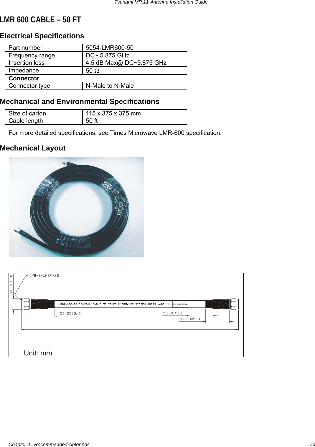
Proxim Wireless MP11R-ABG MP.11x Outdoor Wireless Ethernet System User Manual Tsunami MP 11 Antenna Installation Guide
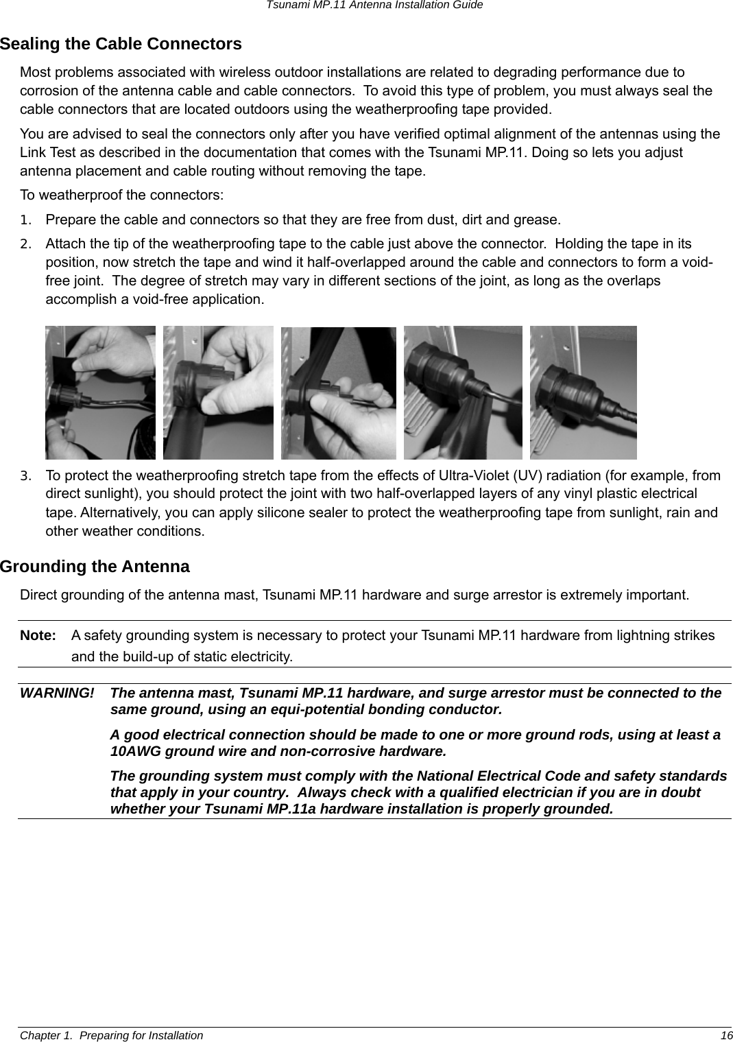
Proxim Wireless Corporation MP.11x Outdoor Wireless Ethernet System Tsunami MP 11 Antenna Installation Guide
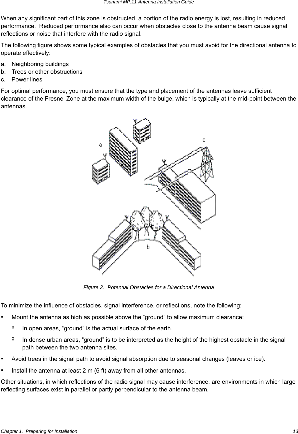
Contents
- 1. Users Manual Part I
- 2. Users Manual Part II
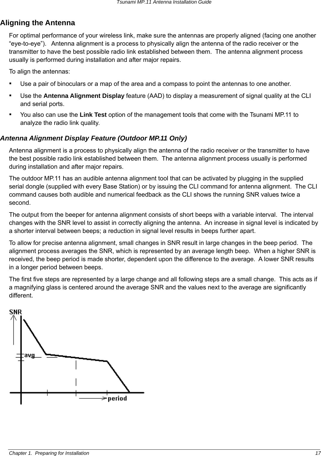
- 3. Professional Installation Guide
- 4. Regulatory Flyer
- 5. manual 1
- 6. manual 2
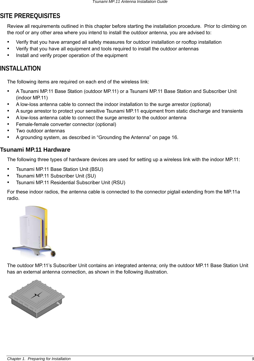
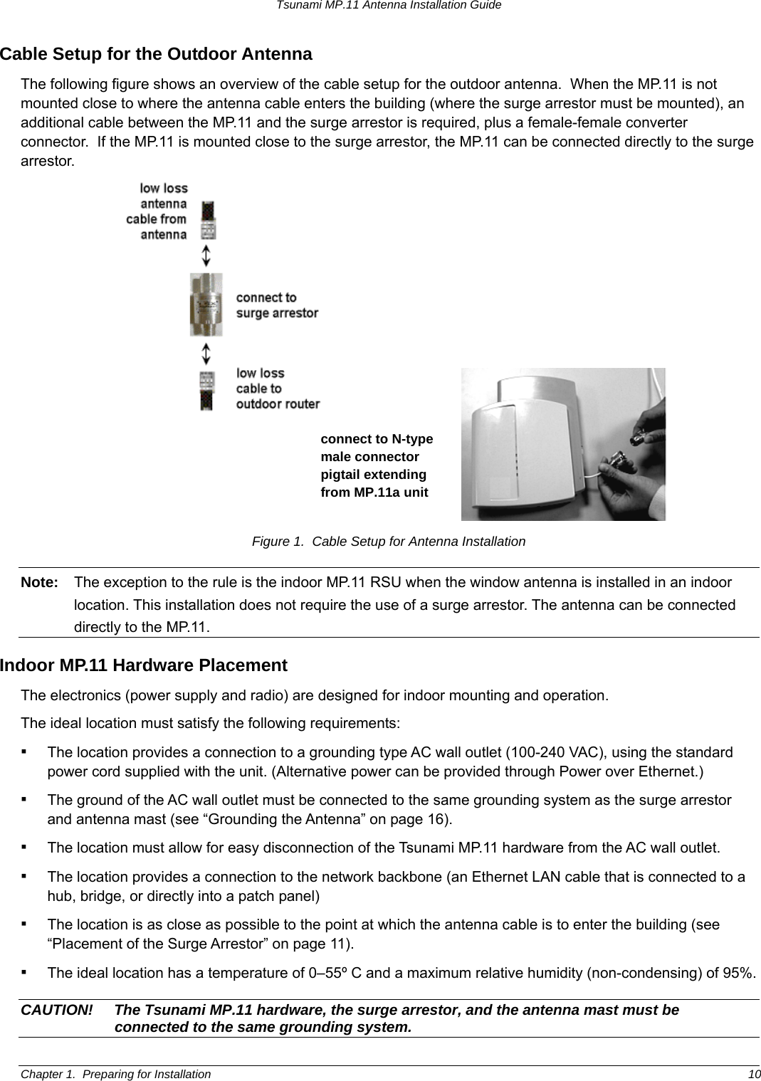
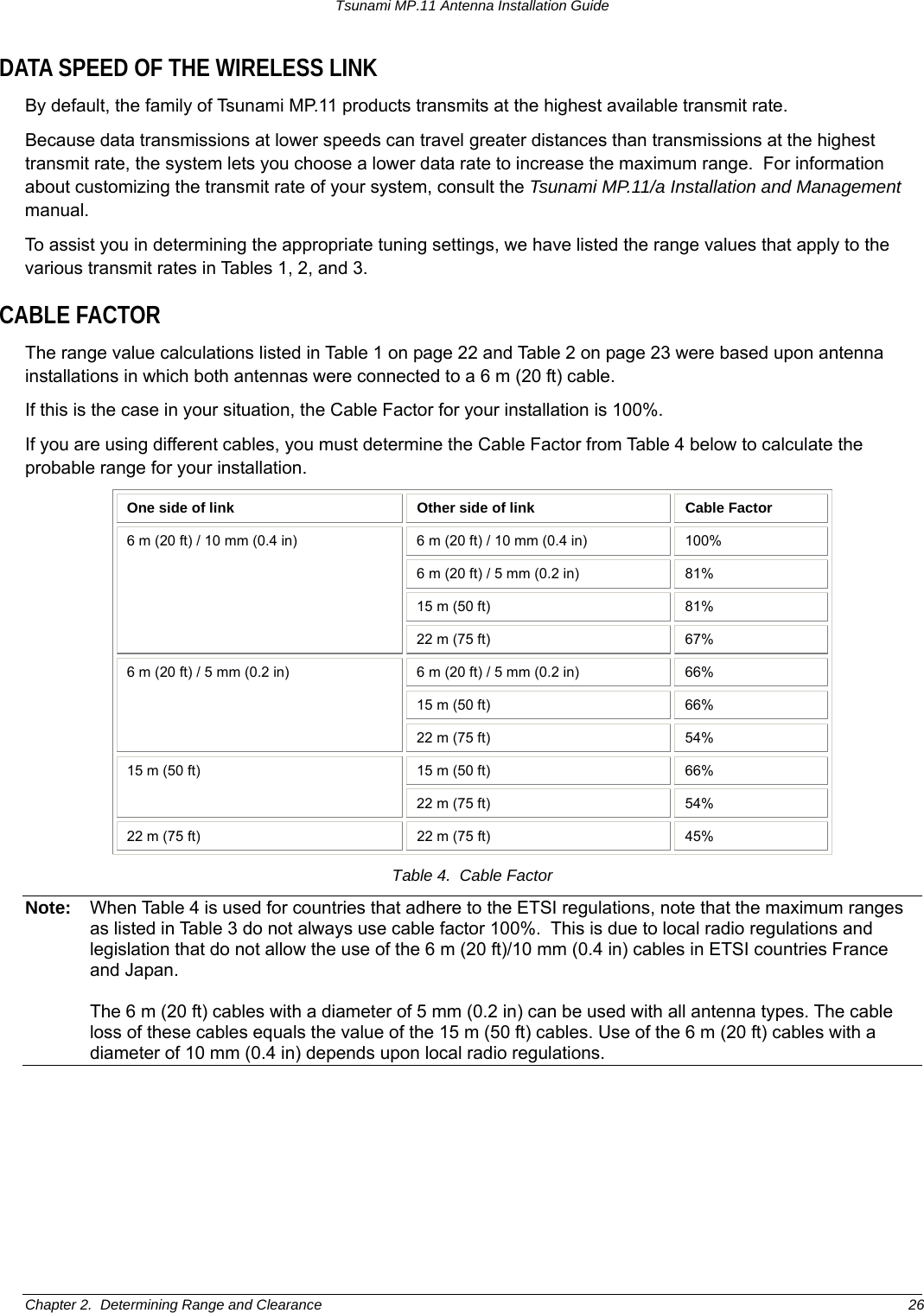
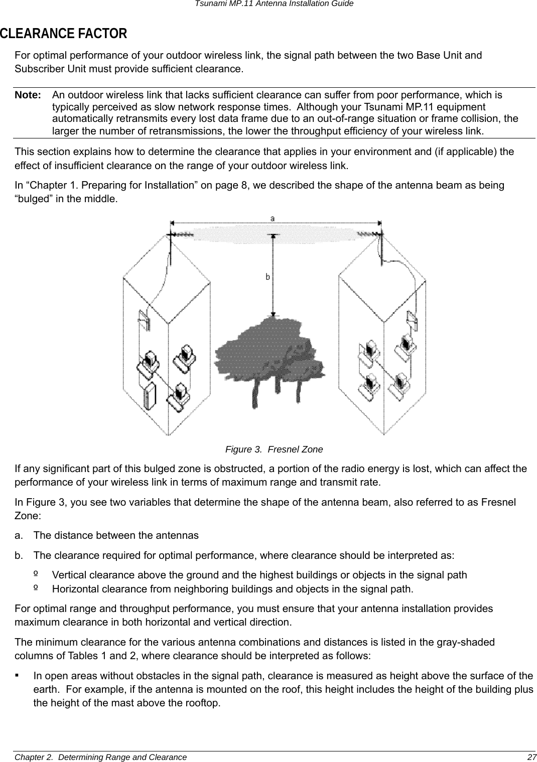
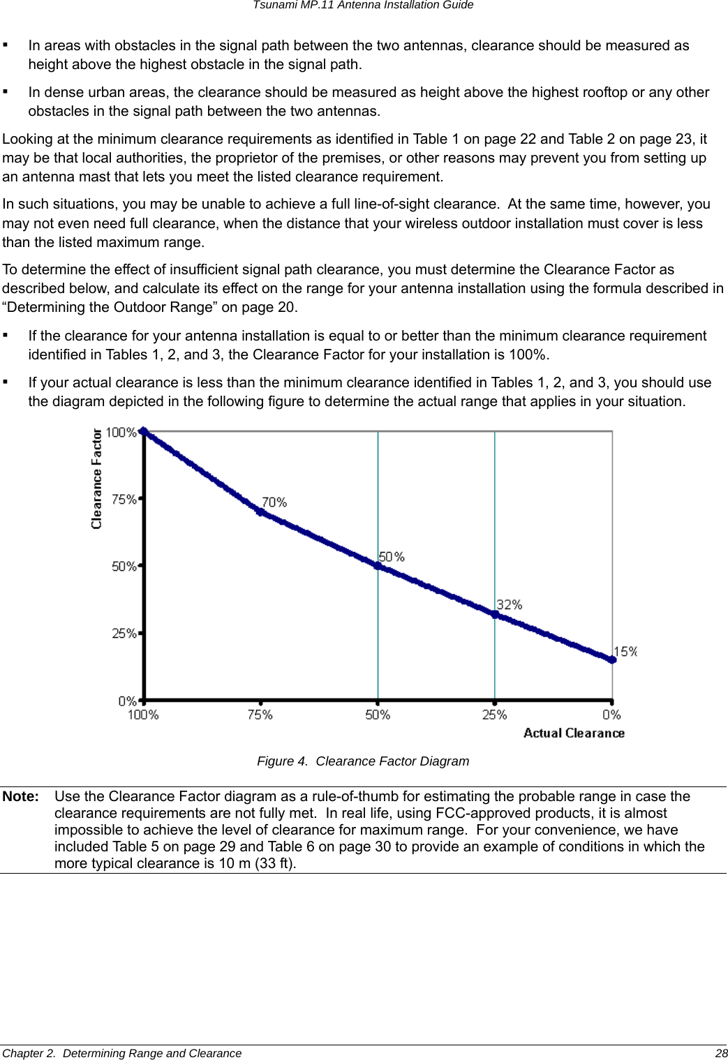
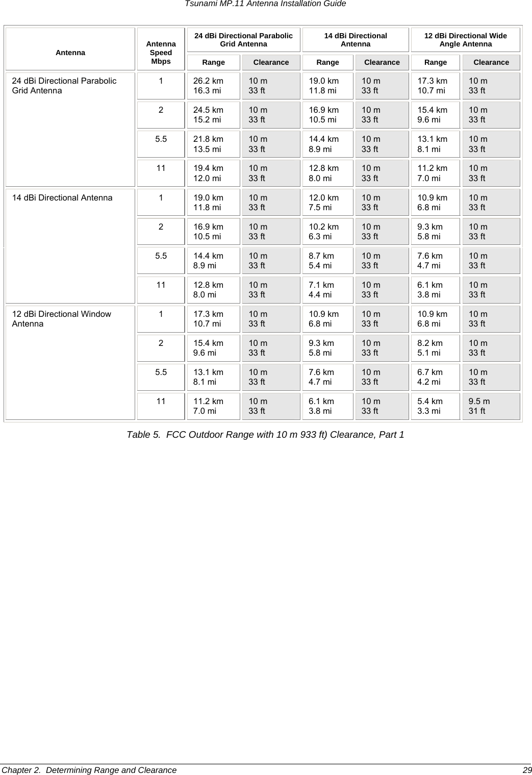
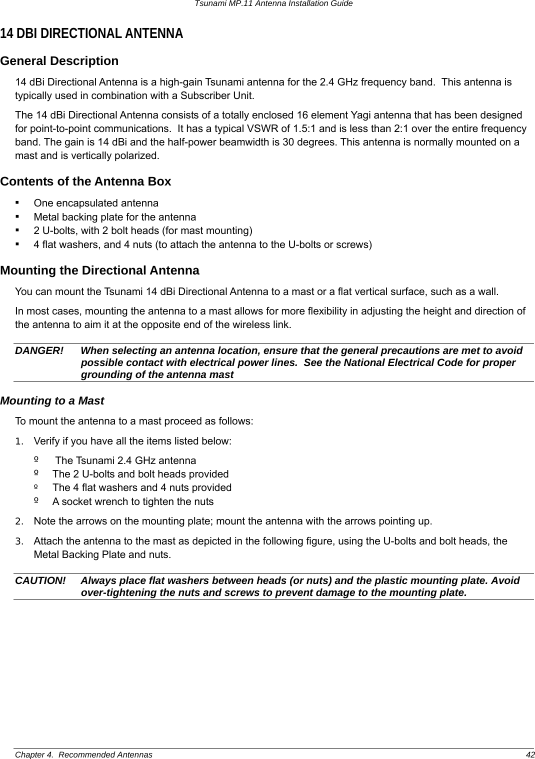
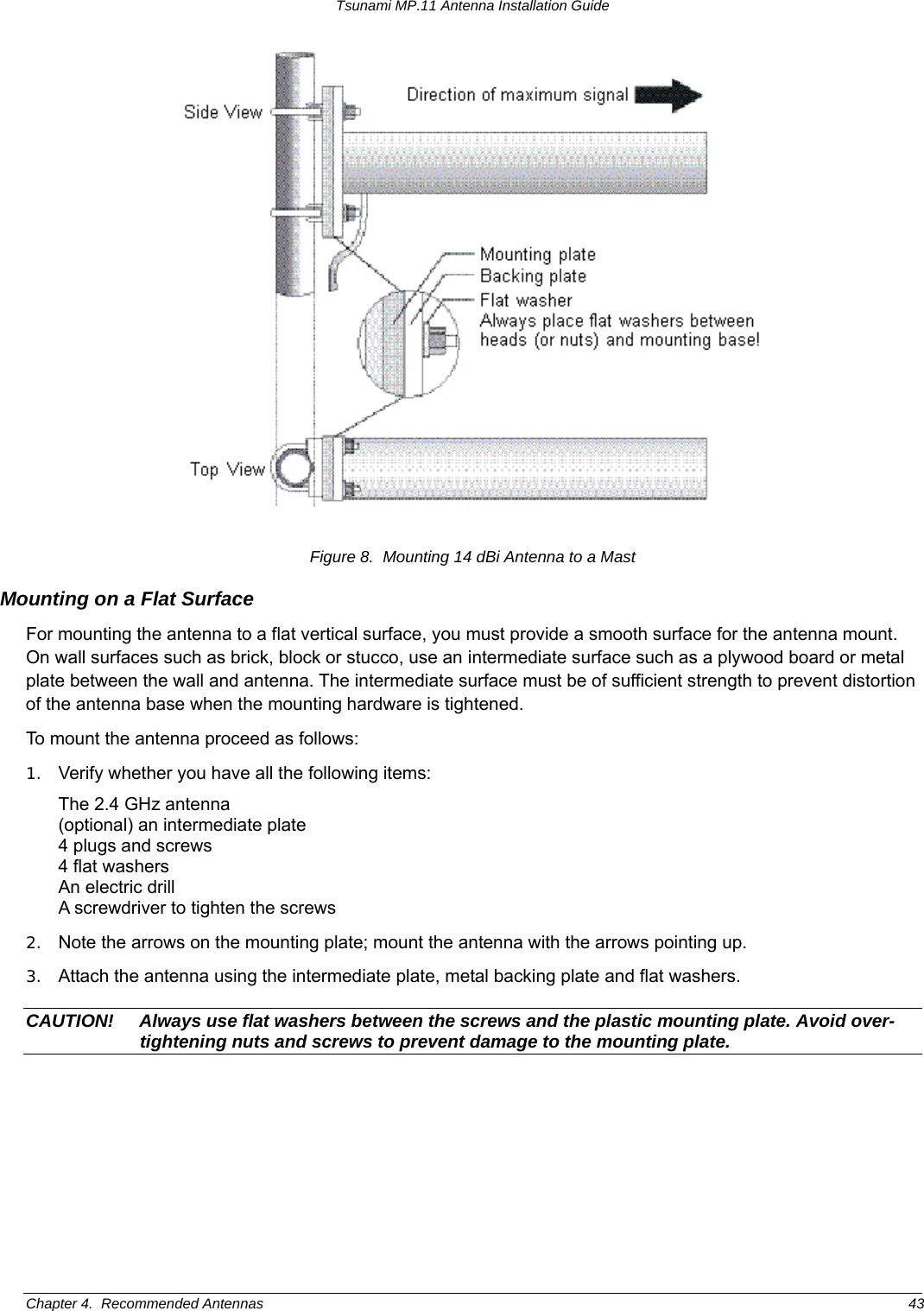
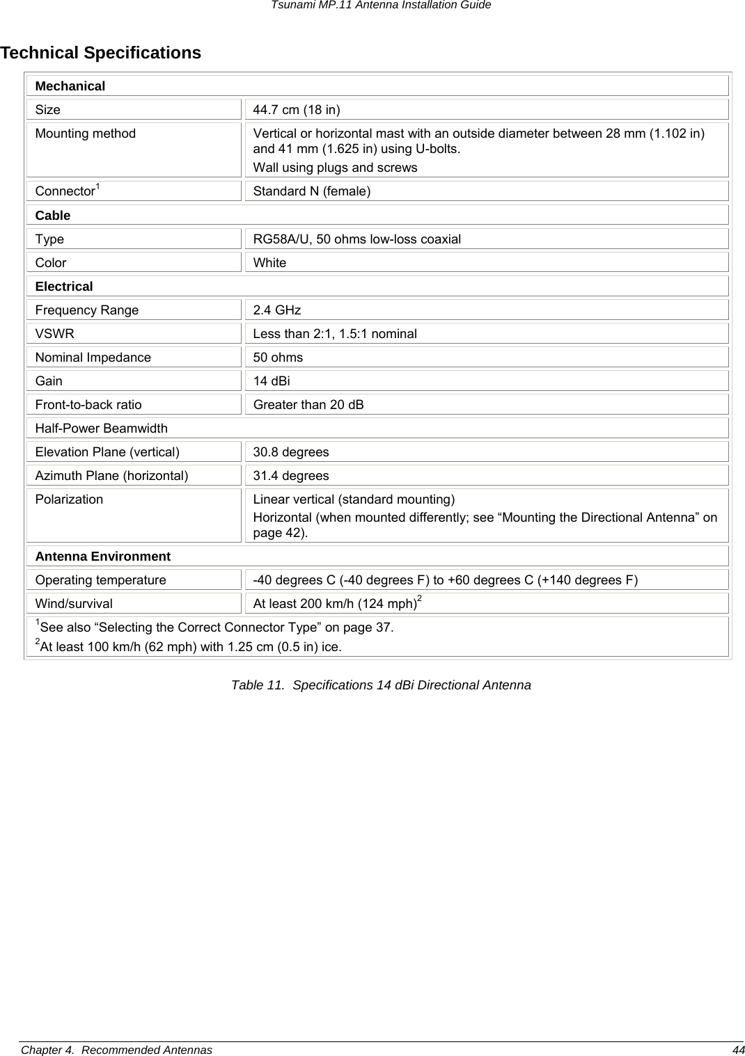
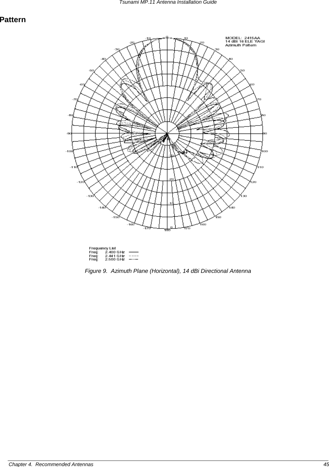
Professional Installation Guide