Proxim Wireless MP11R-ABG MP.11x outdoor wireless Etherenet system User Manual MP 11 R FCC
Proxim Wireless Corporation MP.11x outdoor wireless Etherenet system MP 11 R FCC
UserManual.wiki
>
Proxim Wireless
>
MP11R-ABG User Manual
>
manual 2
Contents
1.
Users Manual Part I
2.
Users Manual Part II
3.
Professional Installation Guide
4.
Regulatory Flyer
5.
manual 1
6.
manual 2
manual 2
Navigation menu
Upload a User Manual
Namespaces
Wiki Guide
HTML
PDF
Info
Views
User Manual
Discussion / Help
Navigation

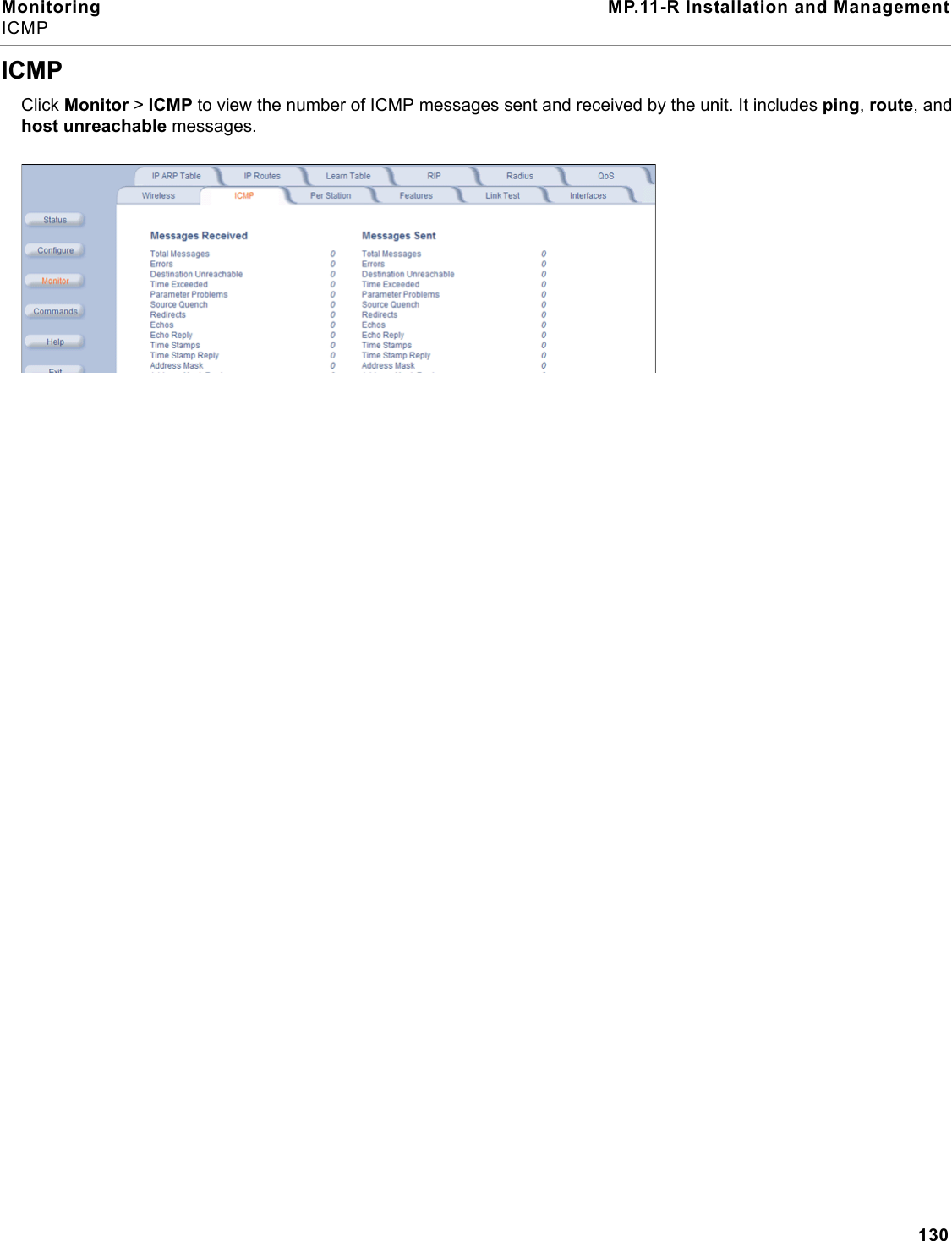
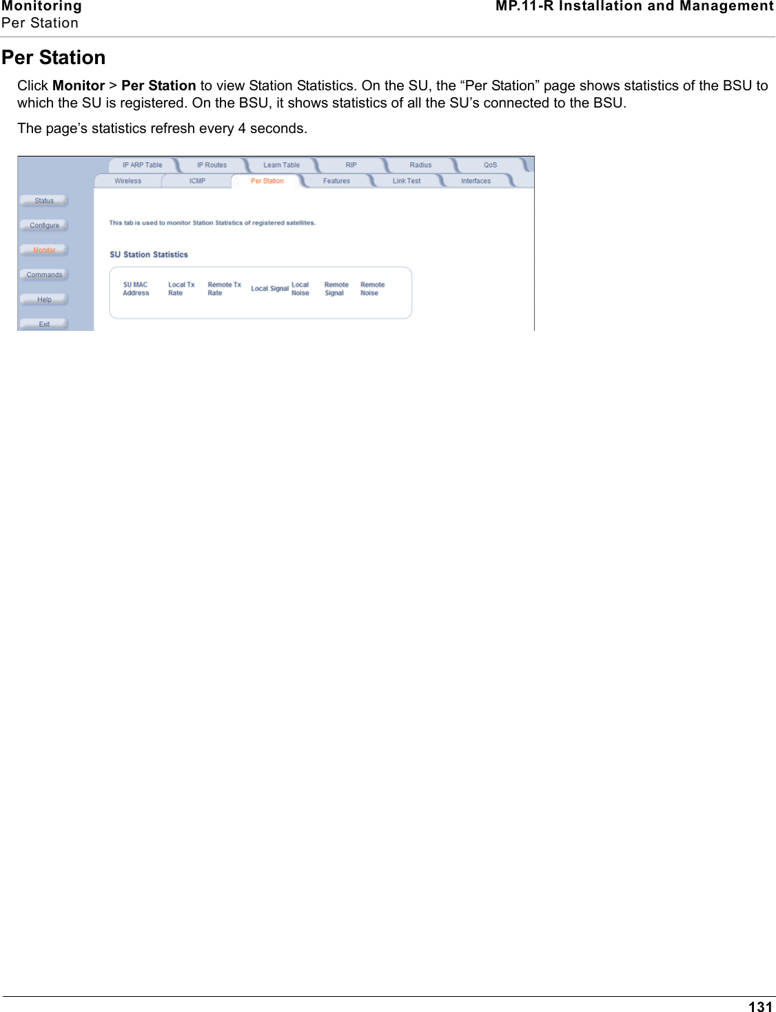
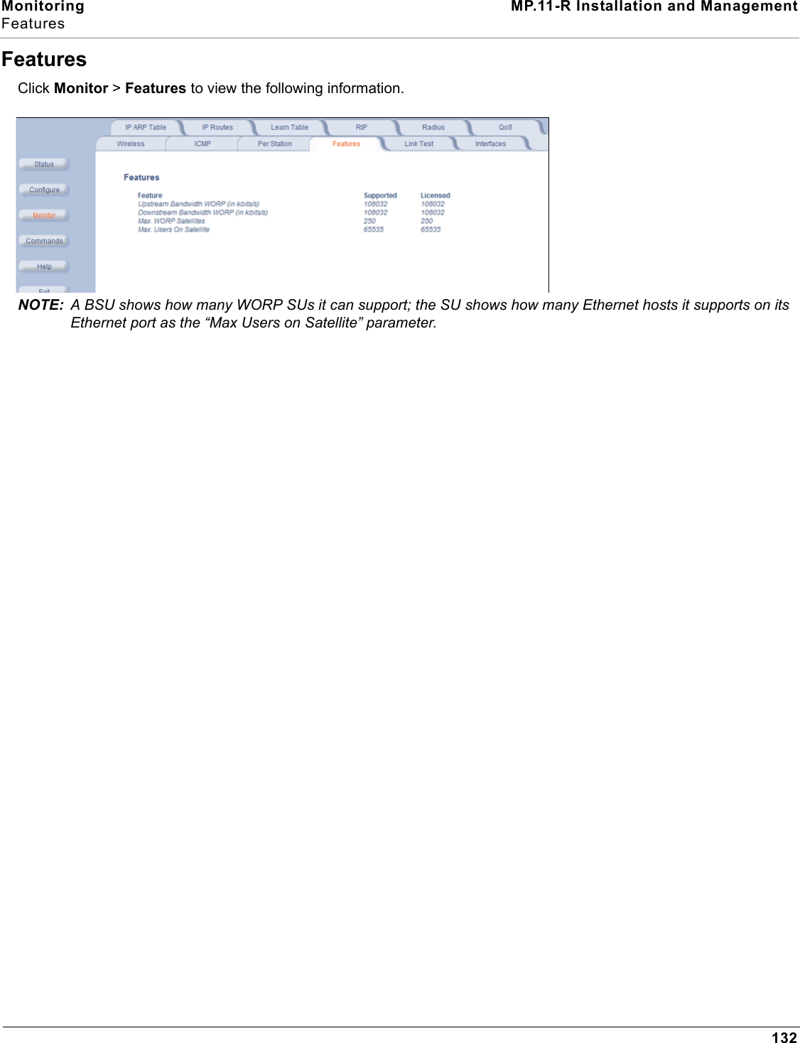
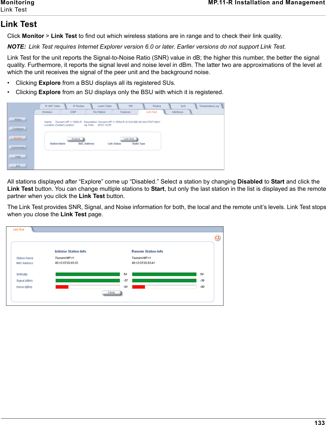
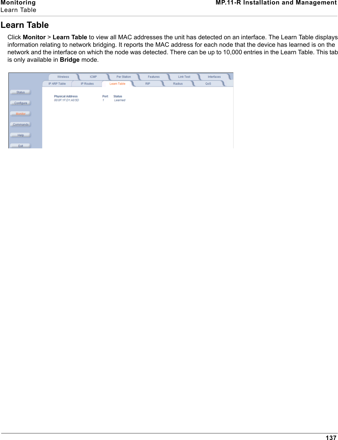

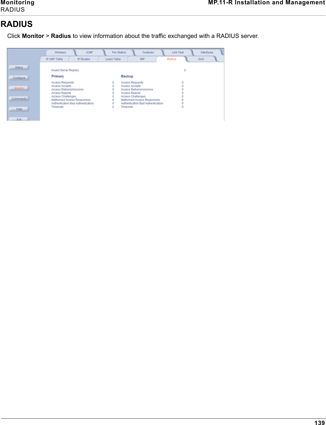
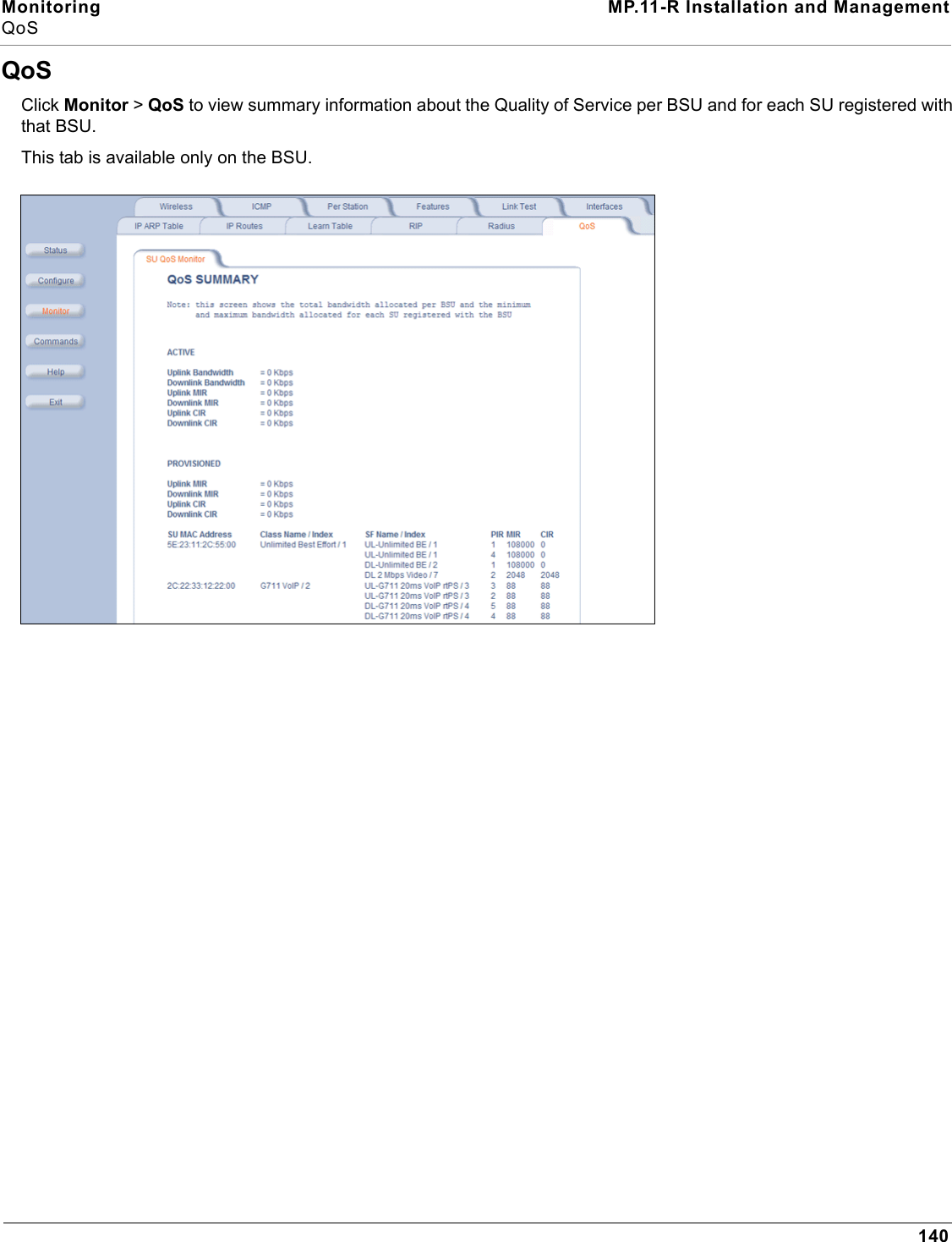
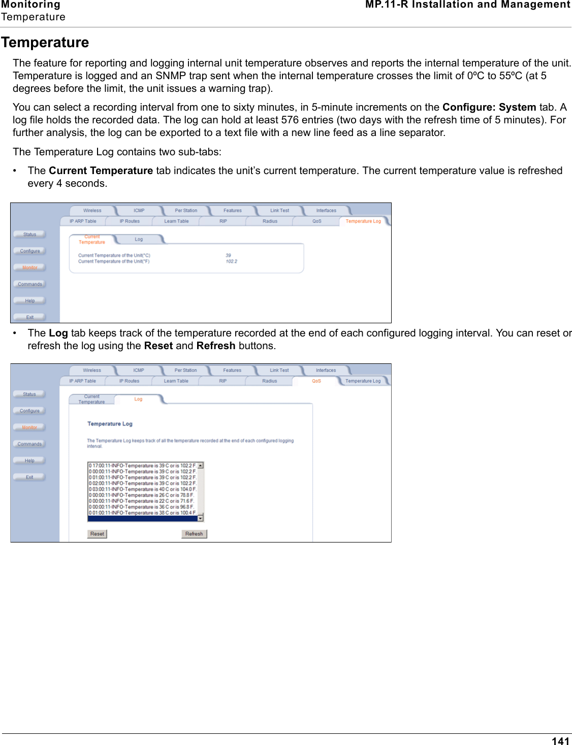
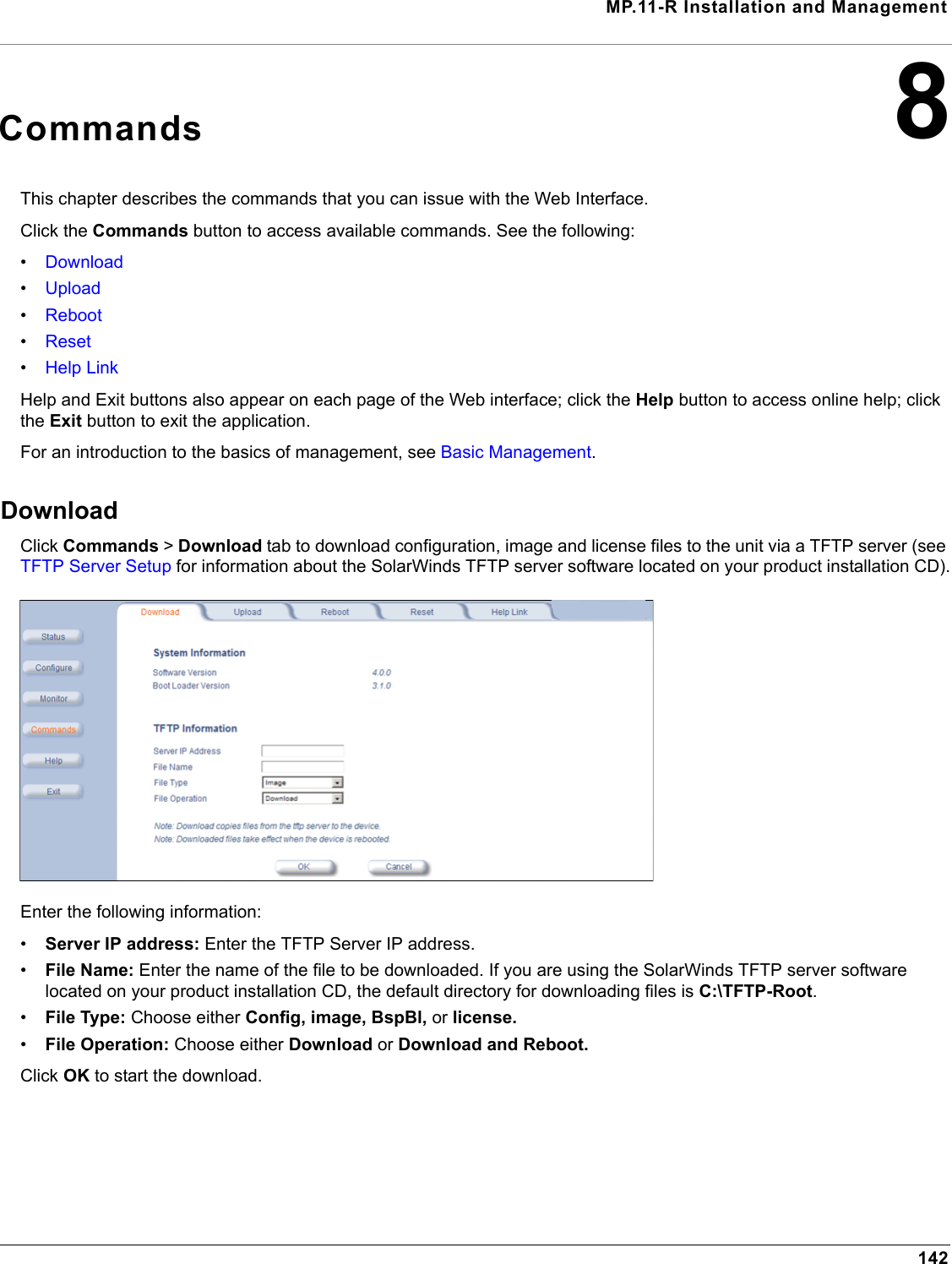
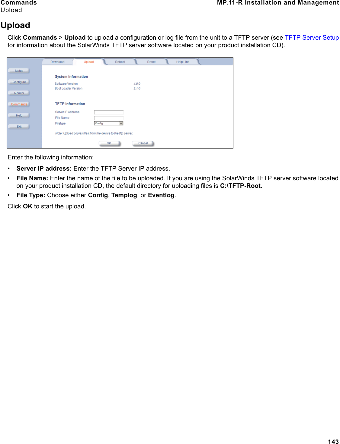
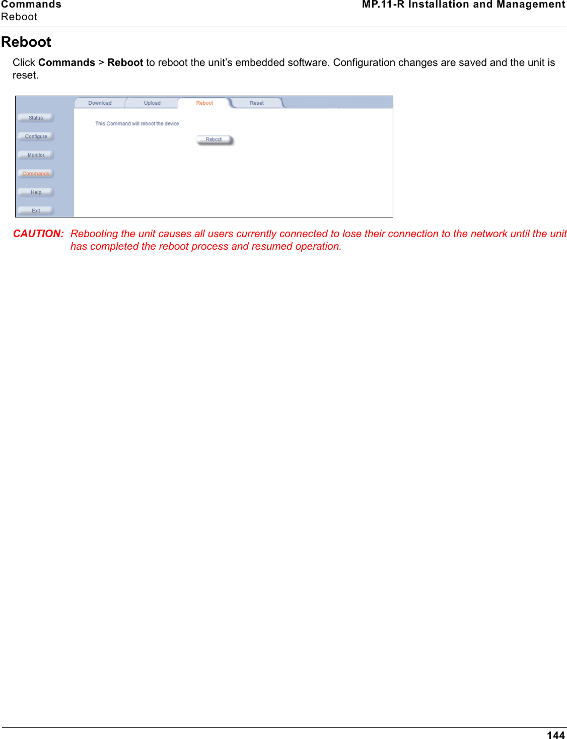
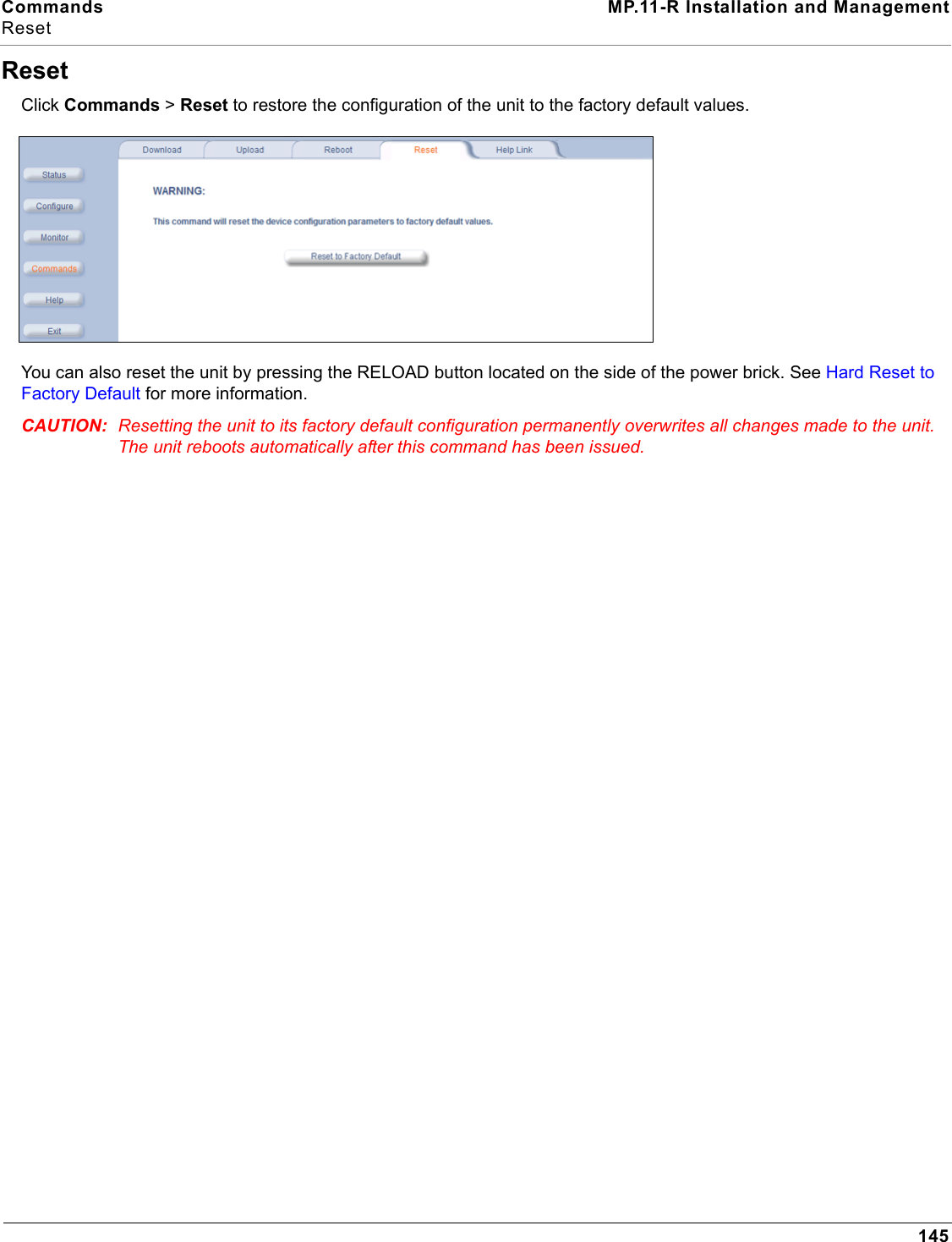
![Commands MP.11-R Installation and ManagementHelp Link146Help LinkClick Commands > Help Link to set the location of the help files of the Web Interface. Upon installation, the help files are installed in the C:\Program Files\Tsunami\MP.11 [Product Name]\Help folder.If you want to place these files on a shared drive, copy the Help folder to the new location and specify the new path in the Help Link box.](https://usermanual.wiki/Proxim-Wireless/MP11R-ABG.manual-2/User-Guide-790135-Page-88.png)