Proxim Wireless MP11R-ABG MP.11x Outdoor Wireless Ethernet System User Manual Tsunami MP 11 Antenna Installation Guide
Proxim Wireless Corporation MP.11x Outdoor Wireless Ethernet System Tsunami MP 11 Antenna Installation Guide
Contents
- 1. Users Manual Part I
- 2. Users Manual Part II
- 3. Professional Installation Guide
- 4. Regulatory Flyer
- 5. manual 1
- 6. manual 2
Professional Installation Guide

Part Number 69143
Tsunami MP.11
Version 2.1
Antenna Installation Guide

NOTICES
Copyright
© 2003, 2004 Proxim Corporation, Sunnyvale, CA. All rights reserved. Covered by one or more of the following U.S.
patents: 5,231,634; 5,875,179; 6,006,090; 5,809,060; 6,075,812; 5,077,753. This manual and the software described
herein are copyrighted with all rights reserved. No part of this publication may be reproduced, transmitted, transcribed,
stored in a retrieval system, or translated into any language in any form by any means without the written permission of
Proxim Corporation.
Trademarks
Tsunami, Proxim, and the Proxim logo are trademarks of Proxim Corporation. All other trademarks mentioned herein are the
property of their respective owners.
REGULATORY INFORMATION
The Tsunami outdoor antenna solution must be installed and used in strict accordance with the instructions as described in
this Antenna Installation Guide.
Note: Radio approvals for the Tsunami outdoor antenna solution are valid only when using the exact combination of
outdoor antenna cabling components and antennas as listed in this Tsunami MP.11a Antenna Installation Guide.
Using other combinations of parts and components in outdoor antenna solutions voids the radio type approval and
may be in violation of local radio regulations.
Proxim Corporation and its authorized resellers or distributors are not liable for any damage or violation of
government regulations that may arise from failing to comply with these guidelines.
This document provides regulatory information for the following wireless products:
▪ Tsunami MP.11a Base Station Unit, Subscriber Unit, Residential Subscriber Unit
This device complies with Part 15 of the FCC Rules. Operation is subject to the following two conditions:
(1) This device may not cause harmful interference
(2) This device must accept any interference received, including interference that may cause undesired operation.
Changes or modifications not expressly approved by Proxim Corporation could void the user's authority to operate the
equipment.
This equipment has been tested and found to comply with the limits for a Class B digital device, pursuant to Part 15 of the
FCC Rules. These limits are designed to provide reasonable protection against harmful interference in a residential
installation.
This equipment generates, uses, and can radiate radio frequency energy and, if not installed and used in accordance with
the instructions, may cause harmful interference to radio communications. However, there is no guarantee that interference
will not occur in a particular installation. If this equipment does cause harmful interference to radio or television reception
(which can be determined by turning the equipment off and on), the user is encouraged to attempt to correct the interference
by one or more of the following measures:
▪ Reorient or relocate the receiving antenna.
▪ Increase the separation between the equipment and receiver.
▪ Connect the equipment into an outlet on a circuit different from that to which the receiver is connected.
▪ Consult the dealer or an experienced radio or television technician for help.
This product must be fixed/mounted on permanent structures with a separation distance of at least two meters from all
persons during normal operation.
Notices 2

Tsunami MP.11 Antenna Installation Guide
Contents
Notices...................................................................................................................................................2
Regulatory Information ..........................................................................................................................2
CONTENTS..................................................................................................................................................3
Figures...................................................................................................................................................3
Tables.....................................................................................................................................................4
ABOUT THIS BOOK....................................................................................................................................5
Who Should Use This Guide .................................................................................................................5
Finding Additional Information ...............................................................................................................6
About the Tsunami MP.11 ......................................................................................................................6
Safety Precautions.................................................................................................................................7
CHAPTER 1. PREPARING FOR INSTALLATION.....................................................................................8
Planning Antenna Installation ................................................................................................................8
Installation Process Overview................................................................................................................8
Site Prerequisites...................................................................................................................................9
Installation..............................................................................................................................................9
Outdoor Installation..............................................................................................................................12
Before Climbing the Roof... .................................................................................................................19
CHAPTER 2. DETERMINING RANGE AND CLEARANCE....................................................................20
Determining the Outdoor Range..........................................................................................................20
Distance Assumptions and Expectations.............................................................................................24
Data Speed of the Wireless Link .........................................................................................................26
Cable Factor ........................................................................................................................................26
Clearance Factor .................................................................................................................................27
Examples .............................................................................................................................................31
CHAPTER 3. ANTENNA CABLING SYSTEM .........................................................................................35
Selecting the Correct Cables...............................................................................................................35
Regulatory Information ........................................................................................................................36
Selecting the Correct Connector Type.................................................................................................37
Outdoor Cabling Components .............................................................................................................39
CHAPTER 4. RECOMMENDED ANTENNAS..........................................................................................41
Type of Outdoor Antenna Equipment ..................................................................................................41
14 dBi Directional Antenna ..................................................................................................................42
7 dBi Omni-Directional Base Unit Antenna..........................................................................................47
10 dBi Omni-Directional Base Unit Antenna........................................................................................51
12 dBi Directional Wide Angle Antenna...............................................................................................55
24 dBi Directional Parabolic Grid Antenna ..........................................................................................59
5 dBi Omni-Directional Antenna ..........................................................................................................65
High Gain Panel Directional Antenna for 2.4 GHz...............................................................................69
Surge Protector....................................................................................................................................71
LMR 600 cable – 50 ft..........................................................................................................................73
SUPPORT AND WARRANTY ...................................................................................................................75
Technical Support ................................................................................................................................75
Warranty and Repair............................................................................................................................75
FIGURES
Figure 1. Cable Setup for Antenna Installation .........................................................................................10
Figure 2. Potential Obstacles for a Directional Antenna ...........................................................................13
Figure 3. Fresnel Zone..............................................................................................................................27
Figure 4. Clearance Factor Diagram.........................................................................................................28
Figure 5. Calculating Point-to-Point Range...............................................................................................31
Figure 6. Calculating Point-to-Multipoint Range .......................................................................................33
Figure 7. Surge Arrestor............................................................................................................................39
Figure 8. Mounting 14 dBi Antenna to a Mast...........................................................................................43
Contents 3

Tsunami MP.11 Antenna Installation Guide
Figure 9. Azimuth Plane (Horizontal), 14 dBi Directional Antenna............................................................45
Figure 10. Elevation Plane (Vertical), 14 dBi Directional Antenna ............................................................46
Figure 11. Mounting the 7 dBi Antenna to a Mast .....................................................................................48
Figure 12. Azimuth Plane (Horizontal), 7 dBi Omni-Directional Base Unit Antenna .................................49
Figure 13. Elevation Plane (Vertical), 7 dBi Omni-Directional Base Unit Antenna ...................................50
Figure 14. Mounting the 10 dBi Antenna...................................................................................................51
Figure 15. Azimuth Plane (Horizontal), 10 dBi Omni-Directional Base Unit Antenna ...............................53
Figure 16. Elevation Plane (Vertical), 10 dBi Omni-Directional Base Unit Antenna .................................54
Figure 17. Mounting the 12 dBi Wide Angle Antenna ...............................................................................55
Figure 18. Azimuth Plane (Horizontal), 12 dBi Directional Wide Angle Antenna ......................................57
Figure 19. Elevation Plane (Vertical), 12 dBi Directional Wide Angle Antenna.........................................58
Figure 20. Assemble the Reflector............................................................................................................60
Figure 21. Determine Polarization.............................................................................................................60
Figure 22. Attach Mounting Bracket ..........................................................................................................61
Figure 23. Azimuth Plane (Horizontal), 24 dBi Directional Parabolic Grid Antenna..................................63
Figure 24. Elevation Plane (Vertical), 24 dBi Directional Parabolic Grid Antenna ....................................64
Figure 25. 5 dBi Omni-Directional Antenna...............................................................................................65
Figure 26. Azimuth Plane (Horizontal), 5 dBi Omni-Directional Antenna..................................................67
Figure 27. Elevation Plane (Vertical), 5 dBi Omni-Directional Antenna ....................................................68
TABLES
Table 1. Maximum Outdoor Range for FCC Products, Part 1...................................................................22
Table 2. Maximum Outdoor Range for FCC Products, Part 2...................................................................23
Table 3. Maximum Range for ETSI/FR/JP Products.................................................................................24
Table 4. Cable Factor ................................................................................................................................26
Table 5. FCC Outdoor Range with 10 m 933 ft) Clearance, Part 1...........................................................29
Table 6. FCC Outdoor Range with 10 m 933 ft) Clearance, Part 2...........................................................30
Table 7. Certified Cable and Antenna Combinations FCC ........................................................................35
Table 8. Certified Channel and Antenna Combinations FCC....................................................................36
Table 9. Standard N-Type Connector Diagram .........................................................................................37
Table 10. Reverse Polarity-N Cabling Diagram ........................................................................................37
Table 11. Specifications 14 dBi Directional Antenna .................................................................................44
Table 12. Specifications 7 dBi Omni-Directional Base Unit Antenna ........................................................48
Table 13. Specifications 10 dBi Omni-Directional Base Unit Antenna ......................................................52
Table 14. Specifications 12 dBi Directional Wide Angle Antenna..............................................................56
Table 15. Specifications 24 dBi Directional Parabolic Grid Antenna .........................................................62
Table 16. Specifications 5 dBi Omni-Directional Antenna .........................................................................66
Contents 4

Tsunami MP.11 Antenna Installation Guide
About This Book
This Tsunami MP.11 Antenna Installation Guide explains how to install and set up an outdoor antenna with the
Tsunami MP.11 hardware.
This guide does not explain how to erect antenna masts or how to install a safety grounding system. These
prerequisites must be in place before installing the directional antenna.
WHO SHOULD USE THIS GUIDE
The installation of outdoor wireless links requires technical expertise. At the very least, you should be able to:
▪ Install and configure the network components, such as the Tsunami MP.11 hardware
▪ Understand, or have a working knowledge of, installation procedures for network operating systems using
Microsoft Windows
▪ Mount the outdoor antenna and surge arrestor. Proxim Corporation recommends the installation is
performed by a qualified antenna installation service
WARNING!
The Tsunami outdoor antennas are intended for mounting on an antenna tower, a roof, or on the side of a
building. Anyone not trained or experienced in this type of work must not attempt this installation. The antenna
must be installed by a suitably trained professional installation technician or by a qualified antenna installation
service. A person familiar with the national electrical code and other regulations governing this type of
installation must check the site prerequisites.
As radio regulations differ between the various worldwide countries, it may be that not all of the outdoor
solutions described in this Tsunami Outdoor Antenna Installation Guide are allowed in the country in which you
plan to install this equipment.
Local radio regulations or legislation may impose restrictions on the use of specific combinations of:
▪ Low-loss antenna cables and outdoor antennas
▪ Radio channels selected at the radios that are connected to specific outdoor antennas
Note: A basic rule for selecting a combination of cables and antennas is that no combination is allowed unless
explicitly approved in this Tsunami Antenna Installation Guide. Therefore, always use this Appendix in
combination with “Chapter 2. Determining Range and Clearance” on page 20 of this document to select
the correct type of antenna equipment and to inform your antenna installer and LAN administrator about
the impact of regulatory constraints on their job or activities.
CAUTION At all times, it is the customer’s responsibility to ensure that an outdoor antenna
installation complies with local radio regulations.1 The customer must verify that:
The antenna installer is aware of these regulations
The correct cable type and surge arrestor have been used, according to the
instructions described in this document
Proxim Corporation and its resellers or distributors are not liable for any damage or
violation of government regulations that may arise from failing to comply with these
guidelines.
1In case you are not certain about the regulations that apply in your country, consult your local Proxim Corporation Sales Office.
About this Book 5

Tsunami MP.11 Antenna Installation Guide
FINDING ADDITIONAL INFORMATION
Installing Tsunami MP.11 Hardware
Tsunami outdoor antennas typically are used in combination with Tsunami MP.11 systems. The hardware
installation of these devices is described in the installation guide included with each product.
Configuration and Management
Configuration and management of outdoor wireless links is accomplished with management tools that come
with the Tsunami MP.11 systems. Some examples of management tools are:
º Web-based management
º Telnet
º Wireless Network Manager
Hardware Specifications
Tsunami MP.11 hardware and radio frequency specifications are described in the documentation that comes
with the product. Hardware specifications for the outdoor antennas, the cabling system, and the surge
arrestor are listed in Chapter 4 of this guide.
Additional Files on Your Software CD-ROM
All software CD-ROMs that come with your Tsunami products, include a readme.txt file. This file contains
information about the software version and drivers. You are advised to print and read the readme.txt file
prior to installing your Tsunami products, as it may contain additional information that was not available
when this document was printed.
Other Sources of Information
All documentation listed above can be downloaded from the Proxim support website:
http://support.proxim.com. Visit the website regularly for the latest available information and documentation,
software updates and other Proxim news.
ABOUT THE TSUNAMI MP.11
The Tsunami MP.11 lets you set up a wireless system based upon two basic topologies:
A point-to-point link lets you set up a connection between two locations as an alternative to:
▪ Leased lines in building-to-building connections
▪ Wired Ethernet backbones between wireless access points in difficult-to-wire environments
If you want to connect more than two buildings, you can set up a single point-to-multipoint network with a single
Base station and multiple Subscriber Units
A link between two locations always consists of a Base Unit and a Subscriber Unit. A Base Unit can, depending
upon its configuration, connect to one or more Subscriber Units; a Subscriber Unit, however, can connect to only
one Base Unit.
Note: Depending upon local radio regulations and legislation, the outdoor antenna solutions described in this
document may not be available in all parts of the world.
About this Book 6

Tsunami MP.11 Antenna Installation Guide
SAFETY PRECAUTIONS
Read this section carefully before beginning the installation. All of the following requirements should be satisfied
prior to starting installation of your outdoor antennas.
DANGER!
The Tsunami outdoor antennas are intended for mounting on a roof or on the side of a building. Any person not
trained or experienced in this type of work should not attempt this installation. A suitably trained professional
installation technician must install the antenna. The site prerequisites must be checked by a person familiar with
the national electrical code, and with other regulations governing this type of installation.
Outdoor antennas and antenna cables are electrical conductors. Transients or electrostatic discharges that may
occur at the antenna (for example a lightning strike during thunderstorms) may damage your electronic
equipment and cause personal injury or death to persons touching the exposed metal connectors of the antenna
cable.
When installing, disconnecting or replacing one of the cabling components, you must ensure at all times that
each exposed metal connectors of the antenna cabling system are grounded locally during the work.
Do not install this antenna where there is any possibility of contact with high-voltage arc-over from power cables
or service drops to buildings. The antenna, supporting mast or tower must not be close to any power lines
during installation, removal or in the event of part of the system should accidentally fail. Apply a ‘Danger’ label to
a plainly visible area of the antenna support structure.
Do not climb rooftops in wet or windy conditions, during a thunderstorm or when the area at which the
equipment is to be installed is covered with ice or snow.
Do not touch antennas, surge arrestors and antenna cables during a thunderstorm.
The antenna installation location must be at a safe distance from power lines or telephone lines. The safe
distance should be at least twice the height of the antenna mast plus the height of the antenna.
Antennas shall be mounted in such a manner as to minimize the potential for human contact during normal
operation. To avoid the possibility of exceeding the FCC radio frequency exposure limits, human proximity to
the antenna shall not be less than 1.12 meters during normal operation.
The low-loss antenna cable that is to connect the antenna with the surge arrestor must be at least 1 m (3 ft)
away from any high voltage or high current cable.
Check whether the antenna mast and its guy wires or wall bracket are positioned correctly and secured properly
to the roof or walls.
Check whether the grounding system for the antenna mast, the Tsunami MP.11a hardware, and the surge
arrestor have been installed. The grounding system must comply with the requirements as described in
“Grounding the Antenna.”
Always consult a qualified electrician if you are in doubt as to whether the antenna mast, the surge arrestor, and
Tsunami MP.11a hardware are properly grounded.
The antenna cable between the antenna and the surge arrestor must be grounded at all times. If the cable is
disconnected at one end for some reason (for example, to replace the surge arrestor), you must ensure that the
exposed metal connector of the cable is grounded locally during the work.
About this Book 7

Tsunami MP.11 Antenna Installation Guide
Chapter 1. Preparing for Installation
PLANNING ANTENNA INSTALLATION
Plan the day for your outdoor antenna installation carefully. Do not install the antenna in wet or windy
conditions, during a thunderstorm, or when the area in which the equipment is to be installed is covered with ice
or snow.
The grounding system for the antenna mast, Tsunami MP.11 hardware, and surge arrestor should be installed
before the cable from the antenna is connected to the surge arrestor. This protects your system against
lightning strikes during installation.
Familiarize yourself with the antenna and the antenna-specific mounting instructions prior to climbing any roof or
ladder. Installing and testing all equipment before beginning the actual rooftop installation helps you determine
whether all required equipment and items are available and are functioning properly.
To verify the equipment prior to installation, first follow the guidelines described in the documentation that comes
with the Tsunami MP.11a.
INSTALLATION PROCESS OVERVIEW
The installation process can be summarized in the following steps:
1. Verify that the support structure for the antenna has been connected to the grounding system. If this is not
the case, you should do so now.
2. Connect the exposed metal connectors of the low-loss antenna cable to the grounding system.
3. Mount the antenna to the support structure, following the guidelines as described for your antenna.
4. Connect the antenna cable to the antenna.
5. Route the antenna cable to the surge arrestor that has been installed indoors.
6. Connect the antenna cable to the surge arrestor.
7. Attach the surge arrestor to the N-type male connector pigtail hanging from the cable opening in the
Tsunami MP.11. For the outdoor MP.11, connect the surge arrestor to the external antenna connection of
the BSU.
8. Run the Link Test diagnostics of the management tools that come with the Tsunami MP.11 to aim the
antenna and verify optimal placement.
Note: For the outdoor MP.11, you can use the Antenna Alignment Display utility. See “Aligning the
Antenna” on page 17.
9. Once the antenna is correctly positioned, and you have verified the installation works properly, secure all
cables and use weatherproofing tape to seal all outdoor connectors.
Note: When you must remove or relocate the antenna, follow the Safety Precautions at the beginning of
this chapter and follow the steps listed above in exactly the reverse order.
Chapter 1. Preparing for Installation 8
Tsunami MP.11 Antenna Installation Guide
SITE PREREQUISITES
Review all requirements outlined in this chapter before starting the installation procedure. Prior to climbing on
the roof or any other area where you intend to install the outdoor antenna, you are advised to:
▪ Verify that you have arranged all safety measures for outdoor installation or rooftop installation
▪ Verify that you have all equipment and tools required to install the outdoor antennas
▪ Install and verify proper operation of the equipment
INSTALLATION
The following items are required on each end of the wireless link:
▪ A Tsunami MP.11 Base Station (outdoor MP.11) or a Tsunami MP.11 Base Station and Subscriber Unit
(indoor MP.11)
▪ A low-loss antenna cable to connect the indoor installation to the surge arrestor (optional)
▪ A surge arrestor to protect your sensitive Tsunami MP.11 equipment from static discharge and transients
▪ A low-loss antenna cable to connect the surge arrestor to the outdoor antenna
▪ Female-female converter connector (optional)
▪ Two outdoor antennas
▪ A grounding system, as described in “Grounding the Antenna” on page 16.
Tsunami MP.11 Hardware
The following three types of hardware devices are used for setting up a wireless link with the indoor MP.11:
▪ Tsunami MP.11 Base Station Unit (BSU)
▪ Tsunami MP.11 Subscriber Unit (SU)
▪ Tsunami MP.11 Residential Subscriber Unit (RSU)
For these indoor radios, the antenna cable is connected to the connector pigtail extending from the MP.11a
radio.
The outdoor MP.11’s Subscriber Unit contains an integrated antenna; only the outdoor MP.11 Base Station Unit
has an external antenna connection, as shown in the following illustration.
Chapter 1. Preparing for Installation 9

Tsunami MP.11 Antenna Installation Guide
Cable Setup for the Outdoor Antenna
The following figure shows an overview of the cable setup for the outdoor antenna. When the MP.11 is not
mounted close to where the antenna cable enters the building (where the surge arrestor must be mounted), an
additional cable between the MP.11 and the surge arrestor is required, plus a female-female converter
connector. If the MP.11 is mounted close to the surge arrestor, the MP.11 can be connected directly to the surge
arrestor.
connect to N-type
male connector
pigtail extending
from MP.11a unit
Figure 1. Cable Setup for Antenna Installation
Note: The exception to the rule is the indoor MP.11 RSU when the window antenna is installed in an indoor
location. This installation does not require the use of a surge arrestor. The antenna can be connected
directly to the MP.11.
Indoor MP.11 Hardware Placement
The electronics (power supply and radio) are designed for indoor mounting and operation.
The ideal location must satisfy the following requirements:
▪ The location provides a connection to a grounding type AC wall outlet (100-240 VAC), using the standard
power cord supplied with the unit. (Alternative power can be provided through Power over Ethernet.)
▪ The ground of the AC wall outlet must be connected to the same grounding system as the surge arrestor
and antenna mast (see “Grounding the Antenna” on page 16).
▪ The location must allow for easy disconnection of the Tsunami MP.11 hardware from the AC wall outlet.
▪ The location provides a connection to the network backbone (an Ethernet LAN cable that is connected to a
hub, bridge, or directly into a patch panel)
▪ The location is as close as possible to the point at which the antenna cable is to enter the building (see
“Placement of the Surge Arrestor” on page 11).
▪ The ideal location has a temperature of 0–55º C and a maximum relative humidity (non-condensing) of 95%.
CAUTION! The Tsunami MP.11 hardware, the surge arrestor, and the antenna mast must be
connected to the same grounding system.
Chapter 1. Preparing for Installation 10

Tsunami MP.11 Antenna Installation Guide
Cable System
CAUTION! The location of the indoor Tsunami MP.11 radio and power supply must be indoors at all
times to protect the unit from extreme weather conditions, excessive heat and humidity,
and to keep the unit free from vibration and dust. The antenna and surge arrestor can be
placed outdoors.
Prior to mounting the Tsunami MP.11, you are advised to calculate carefully:
▪ The distance between the intended location of your Tsunami MP.11 and the location of the antenna mast
▪ The height of the antenna on the mast
If the low-loss antenna cable is not long enough to cover this distance you can select either another cable length
from the Proxim Systems low-loss cable offering, or another location that satisfies the requirements listed
previously to mount your Tsunami MP.11.
Because the length of the antenna cable can affect the actual range of your outdoor antenna installation, Proxim
recommends selecting another location.
WARNING! You must not change the length of the low-loss antenna cable to a length shorter than
allowed by the radio’s certifications. Shortening the cable voids the Proxim Corporation
warranty and can conflict with radio certifications or approvals.
Installing the Tsunami MP.11 hardware is described in Tsunami MP.11/a Installation and Management manual as
well as the Tsunami MP.11/a Quick Install Guide, which come on the Tsunami MP.11 product CD.
Surge Arrestor Placement
The surge arrestor is an indispensable part of your outdoor antenna installation. It protects your sensitive
electronic equipment from transients or electro-static discharges at the antenna.
For optimal protection, the surge arrestor must be installed at a location that satisfies the following requirements:
▪ A location as close to the location where the antenna cable will enter the building (see “Hardware
Placement” on page 10).
▪ The location allows for easy disconnection of the surge arrestor from the cable connected to the unit.
▪ The location provides a connection to the same grounding system as the Tsunami MP.11 hardware and the
outdoor antenna mast (as described in “Grounding the Antenna” on page 16).
Antenna Cable Route
The antenna cable must be connected from the antenna through the surge arrestor to the pigtail connector of
the MP.11 unit or to the external antenna connection of the outdoor MP.11 Base Station. To plan the route of the
antenna cable, consider the following:
▪ Does the cable route require drilling through a wall or ceiling?
▪ Do you have a building plan of the desired location showing other cabling routes like electricity, telephone or
networking?
▪ Does the type of building materials require special drilling tools?
The cable should not be installed into tight positions, as bending or applying excessive force to the connectors
can damage the antenna cable. Always allow the cable to bend naturally around corners. The recommended
bend radius is at least 100 mm (4 in) or more for the low-loss cable of 10 mm (0.4 in) and
15 mm (0.6 in) diameter.
The cable must be secured along the complete distance between attachment points. No part of the antenna
cable should be allowed to hang free. This is particularly important for outdoor cable parts.
Chapter 1. Preparing for Installation 11

Tsunami MP.11 Antenna Installation Guide
CAUTION!
▪ The antenna cable and cable connectors are not designed to withstand excessive force:
º Do not use the connectors as ‘cable grips’ to pull cable through raceways or conduits.
º Do not use the cable connector to support the weight of the cable during or after installation.
º Do not use any tool to tighten the connectors.
▪ Always seal the connectors using weatherproofing tape.
▪ Avoid any water or moisture entering the cable as that impacts the performance of the wireless link.
▪ Prior to sealing the outdoor connectors and permanently securing the cable to the wall with cable
ties and wall hooks, you may want to verify whether the installation and all components functions
properly.
OUTDOOR INSTALLATION
The outdoor installation of the link (point-to-point or point-to-multipoint) requires the following:
▪ An antenna
▪ A low-loss antenna cable (available in three lengths)
▪ Antenna mast or wall bracket for the antenna
▪ A grounding system that meets the requirements described in “Grounding the Antenna” on page 16
▪ Waterproofing of all connections
Note: All outdoor cable connectors must be sealed with weatherproofing stretch tape to make the coax
connectors permanently waterproof. See “Sealing the Cable Connectors” on page 16.
DANGER! For your own safety, the antenna mast and the grounding system should be installed only
by experienced installation professionals who are familiar with local building and safety
codes and with the national electrical codes.
Read carefully the instructions described in “Grounding the Antenna” and verify that your
installation complies with the appropriate regulations and codes before installing the
antenna.
Placing the Antenna
To achieve maximum performance of your wireless outdoor link, the outdoor antenna must have clear line-of-
sight to the antenna of the other Tsunami MP.11 unit. Although the radio signal can work well without line-of-sight
in urban environments, in which the signal is transported by reflection instead of being direct, the best results
are achieved in line-of-sight conditions.
Line-of-sight can be defined as:
▪ No obstacles in the direct path between the antennas (antenna beam)
▪ No obstacles within a defined zone around the antenna beam
You should be aware that the shape of an antenna beam is not straight and narrow like a laser beam. The
antenna beam, also known as Fresnel2 Zone, is rather “bulged” in the middle, such as, for example, a rugby ball.
The exact shape and width of the Fresnel Zone is determined by the path length and frequency of the radio
signal. The width as distance from the direct antenna beam is approximately 6 m (21 ft) in the middle of the
wireless link for a distance of 6.5 Km (4 mi) and a frequency of 5.8 GHz. This width also is the required
clearance of the antenna beam from obstacles in its path, to avoid loss of radio signal.
2Pronounced as ‘Fray-Nell’
Chapter 1. Preparing for Installation 12
Tsunami MP.11 Antenna Installation Guide
When any significant part of this zone is obstructed, a portion of the radio energy is lost, resulting in reduced
performance. Reduced performance also can occur when obstacles close to the antenna beam cause signal
reflections or noise that interfere with the radio signal.
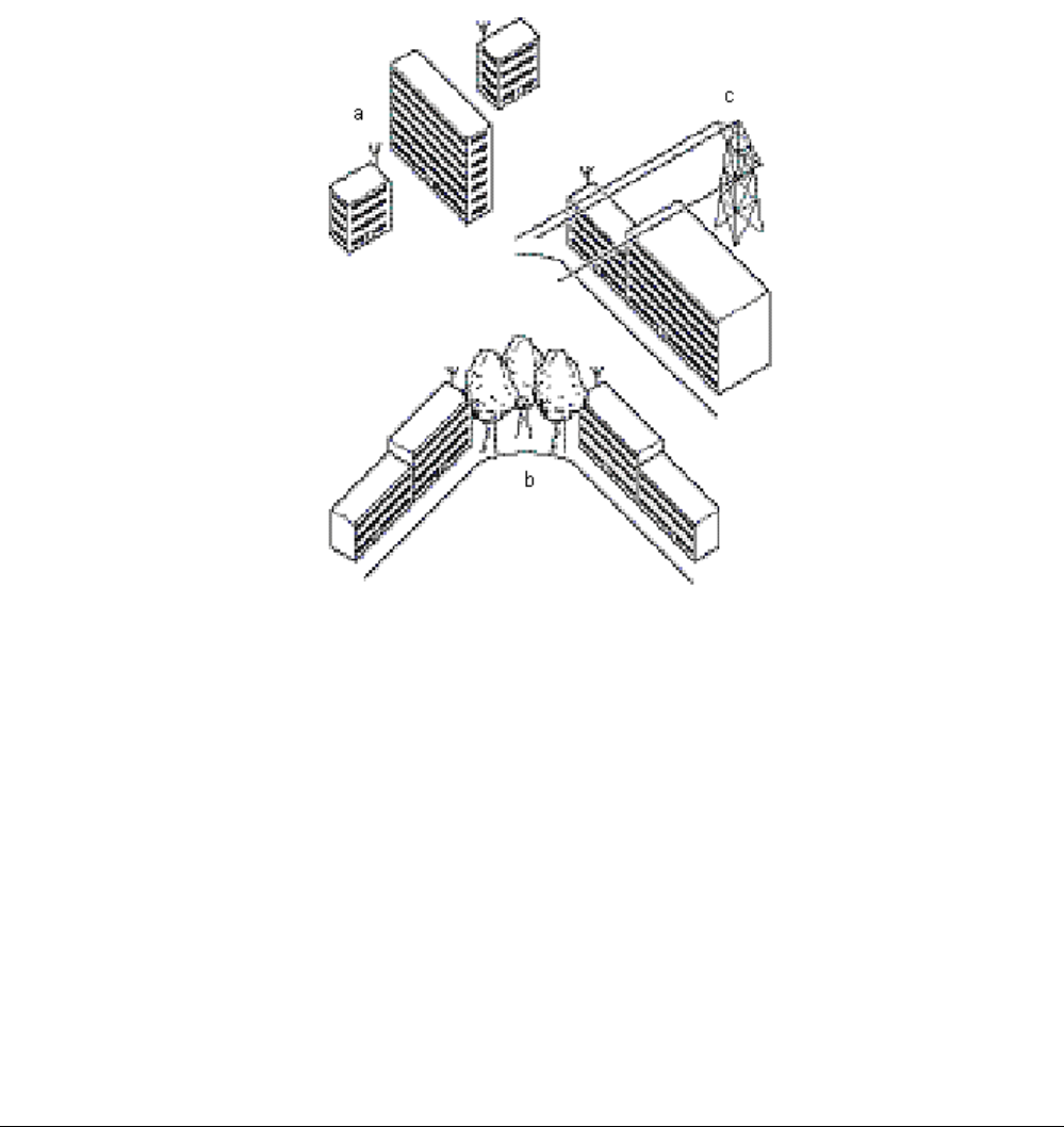
The following figure shows some typical examples of obstacles that you must avoid for the directional antenna to
operate effectively:
a. Neighboring buildings
b. Trees or other obstructions
c. Power lines
For optimal performance, you must ensure that the type and placement of the antennas leave sufficient
clearance of the Fresnel Zone at the maximum width of the bulge, which is typically at the mid-point between the
antennas.
Figure 2. Potential Obstacles for a Directional Antenna
To minimize the influence of obstacles, signal interference, or reflections, note the following:
▪ Mount the antenna as high as possible above the “ground” to allow maximum clearance:
º In open areas, “ground” is the actual surface of the earth.
º In dense urban areas, “ground” is to be interpreted as the height of the highest obstacle in the signal
path between the two antenna sites.
▪ Avoid trees in the signal path to avoid signal absorption due to seasonal changes (leaves or ice).
▪ Install the antenna at least 2 m (6 ft) away from all other antennas.
Other situations, in which reflections of the radio signal may cause interference, are environments in which large
reflecting surfaces exist in parallel or partly perpendicular to the antenna beam.
Chapter 1. Preparing for Installation 13

Tsunami MP.11 Antenna Installation Guide
Environments with large reflective surfaces include:
▪ Mirror-glass buildings
▪ Crowded parking lots
▪ Water surface or moist earth and moist vegetation
▪ Above ground power and telephone lines
Note: The use of reflective surfaces can be used to improve a link, especially if the direct line-of-sight is
impaired or absent.
Weather conditions such as rain or snow usually do not have much impact on the performance of your Tsunami
MP.11 product, provided you have sealed all cable connectors with weatherproofing tape.
Seasonal influence on signal propagation can occur in the following situations:
▪ A marginal communications quality in late fall (with no leaves on the trees in the signal path) might fail in the
summer
▪ In winter, a wireless link can fail when the antenna is exposed to ice buildup, or when the antenna elements
are covered with snow
Radio paths over water or extremely flat ground may require optimization of antenna height at one end. This is
due to in-phase or out-of-phase reflections. Adjustment of antenna height by 1 to 3 meters may move the signal
from a null to a peak.
Long distance links may be obstructed by earth curvature, so the antenna height requirements must not only
take the height of obstructions and Fresnel Zone into account, but also earth bulge. The earth bulge is
approximately 5 m (16.4 ft) at a link distance of 16 Km (10 mi).
In these cases consult your supplier to take appropriate steps to maintain or optimize wireless link performance.
Mounting the Antenna
As the mounting procedures for the various antennas differ from one another, consult the documentation you
received from the antenna manufacturer for mounting procedures.
Proxim Corporation offers multiple antennas to set up a wireless link.
When mounting multiple antennas on a single mast, use the following methods to minimize the influence of
cross-talk interference between the antennas:
▪ Place your antennas as far apart as you can
▪ Alternate the mounting of directional antennas for vertical and horizontal polarization
There are two frequently used methods to erect an antenna mast:
Tripod Mount
The tripod mount is used primarily on peaked and flat roofs. The antenna mast must be secured to the roof
using 3 or 4 guy wires equally spaced around the mast. When the height of the antenna mast is more than 3
meters (10 ft), you should use at least three guy wires for each 3-meter (10-foot) section of the mast.
Wall (Side) Mount
A wall (side) mount allows for mounting an antenna (mast) on the side of a building or on the side of an
elevator penthouse. This provides a convenient mounting location when the roof overhang is not excessive
or when the location is high enough to provide a clear line-of-sight.
Chapter 1. Preparing for Installation 14

Tsunami MP.11 Antenna Installation Guide
In most situations mounting an antenna directly to the wall does not let you align the antenna properly with
the corresponding antenna at the opposite end of your wireless link. As poor alignment typically results in
poor performance, Proxim recommends always mounting the antennas to a mast. An exception to this rule
is the wide-angle window antenna that can be mounted on a window or wall facing the nearest Base Station
with line of sight.
Antenna Mast Requirements
To accommodate the antennas, the antenna mast must satisfy the following requirements:
▪ The construction of the mast must consist of sturdy, weatherproof, and non-corrosive material (for example,
galvanized or stainless steel construction pipe).
▪ Typical diameter of the mast should be between 35 mm (1.4 in) and 41 mm (1.6 in). Depending upon the
type of antenna you intend to install, other diameters also may be possible.
▪ The height of the antenna mast must be sufficient to allow the antenna to be installed at least 1.5 m (5 ft)
above the peak of the roof. If the roof is of metal, the height of the antenna should be at least 3 m (10 ft)
above the roof.
▪ The mast or wall bracket must be free from any substance that may prevent a good electrical connection
with the antenna (for example, paint).
Connecting the Antenna Cable
Once the antenna is properly installed, you can connect the antenna to the MP.11 by way of the surge arrestor:
1. Connect the antenna cable to the antenna.
2. Secure the antenna cable to the mast so that the cable connectors do not support the full weight of the
cable.
3. Connect the opposite end of the antenna cable to the surge arrestor.
CAUTION! To avoid damage to the antenna cable and connectors, refrain from using tools to
tighten the cable connectors.
4. Prior to securing the cable along its complete length, run the Link Test diagnostics of the management tools
that comes with Tsunami MP.11 to analyze wireless performance and optimal placement of the outdoor
antenna. Using this tool is described in the documentation that comes with the Tsunami MP.11 and also can
be downloaded from the Proxim support website at http://support.proxim.com .
5. If required, adjust the direction of the antenna.
6. Once the installation has been fully tested, tighten the nuts of the antenna to “lock” the antenna into its
position.
CAUTION! Avoid over-tightening of the connector, and nuts and screws used to mount the
antenna, to prevent damage to your antenna and Tsunami MP.11 hardware.
7. Secure the cable along its complete length with cable ties or electrical tape to relieve strain on the antenna
connector properly. No part of the cable should be allowed to hang free. This is especially important for
those parts that are routed outside the building.
8. Proceed as described in the next section to weatherproof all outdoor coax connectors.
Chapter 1. Preparing for Installation 15
Tsunami MP.11 Antenna Installation Guide
Sealing the Cable Connectors
Most problems associated with wireless outdoor installations are related to degrading performance due to
corrosion of the antenna cable and cable connectors. To avoid this type of problem, you must always seal the
cable connectors that are located outdoors using the weatherproofing tape provided.
You are advised to seal the connectors only after you have verified optimal alignment of the antennas using the
Link Test as described in the documentation that comes with the Tsunami MP.11. Doing so lets you adjust
antenna placement and cable routing without removing the tape.
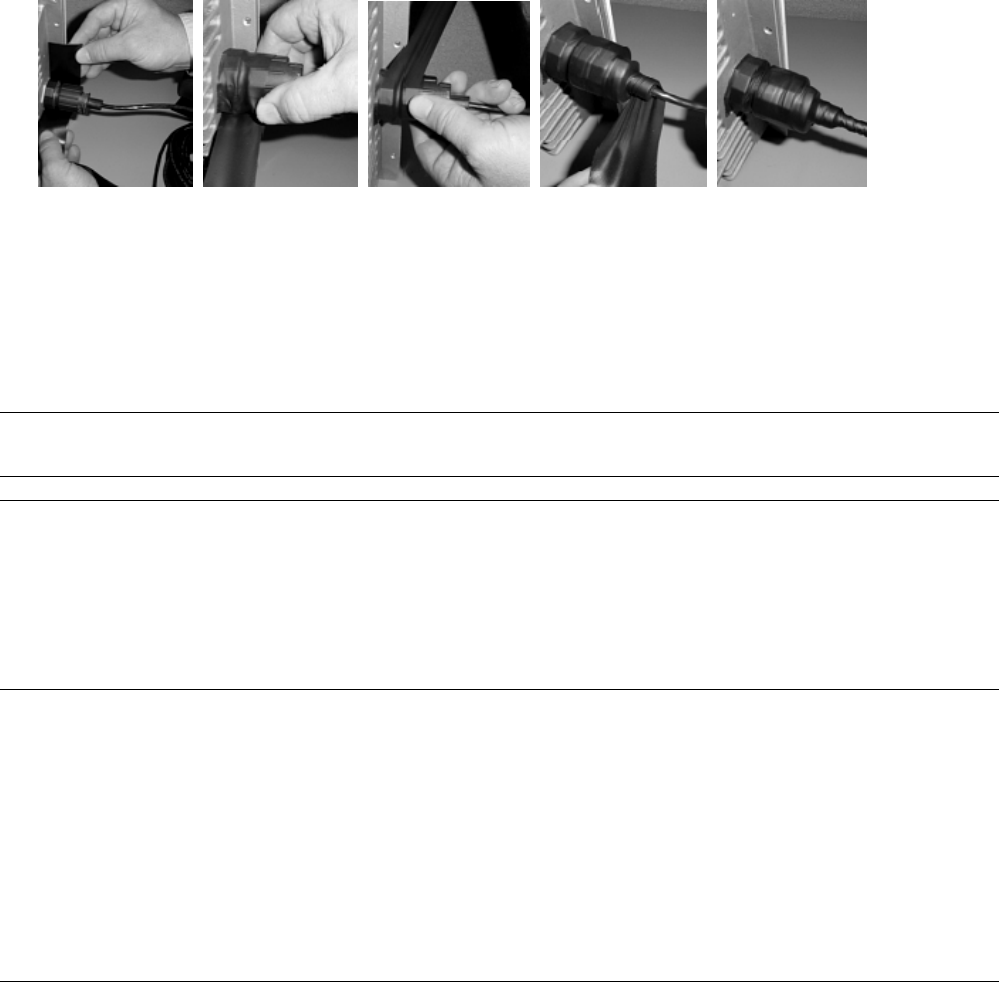
To weatherproof the connectors:
1. Prepare the cable and connectors so that they are free from dust, dirt and grease.
2. Attach the tip of the weatherproofing tape to the cable just above the connector. Holding the tape in its
position, now stretch the tape and wind it half-overlapped around the cable and connectors to form a void-
free joint. The degree of stretch may vary in different sections of the joint, as long as the overlaps
accomplish a void-free application.
3. To protect the weatherproofing stretch tape from the effects of Ultra-Violet (UV) radiation (for example, from
direct sunlight), you should protect the joint with two half-overlapped layers of any vinyl plastic electrical
tape. Alternatively, you can apply silicone sealer to protect the weatherproofing tape from sunlight, rain and
other weather conditions.
Grounding the Antenna
Direct grounding of the antenna mast, Tsunami MP.11 hardware and surge arrestor is extremely important.
Note: A safety grounding system is necessary to protect your Tsunami MP.11 hardware from lightning strikes
and the build-up of static electricity.
WARNING! The antenna mast, Tsunami MP.11 hardware, and surge arrestor must be connected to the
same ground, using an equi-potential bonding conductor.
A good electrical connection should be made to one or more ground rods, using at least a
10AWG ground wire and non-corrosive hardware.
The grounding system must comply with the National Electrical Code and safety standards
that apply in your country. Always check with a qualified electrician if you are in doubt
whether your Tsunami MP.11a hardware installation is properly grounded.
Chapter 1. Preparing for Installation 16
Tsunami MP.11 Antenna Installation Guide
Aligning the Antenna
For optimal performance of your wireless link, make sure the antennas are properly aligned (facing one another
“eye-to-eye”). Antenna alignment is a process to physically align the antenna of the radio receiver or the
transmitter to have the best possible radio link established between them. The antenna alignment process
usually is performed during installation and after major repairs.
To align the antennas:
▪ Use a pair of binoculars or a map of the area and a compass to point the antennas to one another.
▪ Use the Antenna Alignment Display feature (AAD) to display a measurement of signal quality at the CLI
and serial ports.
▪ You also can use the Link Test option of the management tools that come with the Tsunami MP.11 to
analyze the radio link quality.
Antenna Alignment Display Feature (Outdoor MP.11 Only)
Antenna alignment is a process to physically align the antenna of the radio receiver or the transmitter to have
the best possible radio link established between them. The antenna alignment process usually is performed
during installation and after major repairs.
The outdoor MP.11 has an audible antenna alignment tool that can be activated by plugging in the supplied
serial dongle (supplied with every Base Station) or by issuing the CLI command for antenna alignment. The CLI
command causes both audible and numerical feedback as the CLI shows the running SNR values twice a
second.
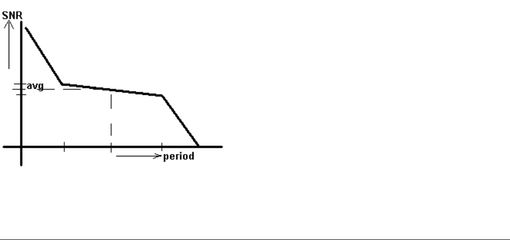
The output from the beeper for antenna alignment consists of short beeps with a variable interval. The interval
changes with the SNR level to assist in correctly aligning the antenna. An increase in signal level is indicated by
a shorter interval between beeps; a reduction in signal level results in beeps further apart.
To allow for precise antenna alignment, small changes in SNR result in large changes in the beep period. The
alignment process averages the SNR, which is represented by an average length beep. When a higher SNR is
received, the beep period is made shorter, dependent upon the difference to the average. A lower SNR results
in a longer period between beeps.
The first five steps are represented by a large change and all following steps are a small change. This acts as if
a magnifying glass is centered around the average SNR and the values next to the average are significantly
different.
Chapter 1. Preparing for Installation 17

Tsunami MP.11 Antenna Installation Guide
When the antenna is aimed, the beep can easily be heard if the SNR is rising (shorter period, higher frequency)
or falling (longer period). When the position of the antenna has been changed, the SNR averaging settles at the
new value and the beeping returns to the average length so the antenna can again be aimed towards rising
SNR.
Aiming is complete if moving in any direction results in a falling SNR value, which can be heard as longer
periods between beeps.
Notes:
▪ Antenna alignment for the Base Station is useful only for a point-to-point link.
▪ The range of the average SNR must be limited to values from 0 to 48. Anything over 48 is capped at 48.
▪ AAD is automatically disabled 30 minutes after it is enabled to remove the load of extra messages on the
wireless interface. The default telnet timeout is 900 seconds (15 minutes). If AAD must run for the entire 30
minutes, change the default telnet timeout value greater than 30 minutes (greater than 1800 seconds). This
restriction is for telnet connections only and not for the serial interface. The serial interface never times out.
Antenna Alignment Commands
set aad enable local
Enables display of the local SNR. Local SNR is the SNR measured by the receiver at the near end.
set aad enable remote
Enables display of the remote SNR. Remote SNR is the SNR as measured by the receiver at the far end.
set aad enable average
Enables display of the average SNR. The average SNR is the average of the local and remote SNR.
set aad disable
Disables Antenna Alignment Display (Ctrl-C also disables AAD).
Link Test
You also can use the Link Test option of the management tools that come with the Tsunami MP.11 to analyze
the radio link quality. The Link Test option lets you display the radio signal strength in relation to the noise in the
signal path. If required, you can interactively optimize the antenna alignment with the Link Test, by making small
modifications in the antenna orientation.
The “AudioTune” tool can be used to read out loud the Link Test values, allowing direct feedback when aligning
the antenna. Run the Link Test diagnostics of the management tools that come with the Tsunami MP.11 with the
Signal and Noise fields selected.
You can download AudioTune from http://www.computron-usa.com/wireless_utilities.htm.
Alternatively, consult a professional Antenna Installation Service to optimize the antenna alignment.
Antenna Polarization
Tsunami outdoor antennas are standard mounted for vertical polarization.
In some cases, you might consider mounting the antenna for horizontal polarization. For example, to minimize
the influence of cross-talk between antennas when:
▪ You plan to mount multiple directional antennas to the same mast.
▪ Your wireless link receives interference from a vertically polarized neighboring installation.
Mounting for horizontal polarization is not supported for omni-directional grid antennas.
Chapter 1. Preparing for Installation 18

Tsunami MP.11 Antenna Installation Guide
Note: For optimal wireless link performance, you must always verify that the antenna polarization on both
ends of the wireless link is the same. Consult the corresponding instruction appendixes for changing
the antenna polarization.
Antenna Cable Routing
The antenna cable must be routed and fixed in such a way that installation technicians have a clear passage
area.
All connectors that are located outdoors must have a weatherproof seal. You are advised to seal connectors
only after you have completed the final radio tests.
BEFORE CLIMBING THE ROOF...
Before you start the installation, check whether you have all the required components to set up an outdoor
wireless link.
For each side of a wireless outdoor wireless link you need:
▪ One or two low-loss antenna cables
▪ A female-female converter N-connector in case you want to use two antenna cables
▪ Tools and material to mount the antenna
▪ Tape or wraps to attach the antenna cable, for example to the mast
▪ Grounding material such as cable and connector
If an item is missing or damaged during shipment, inform your supplier.
Chapter 1. Preparing for Installation 19

Tsunami MP.11 Antenna Installation Guide
Chapter 2. Determining Range and Clearance
When you read about wireless outdoor products, you often encounter the terms output power of the radio and
gain of the antenna equipment as measures for the strength of the transmitted signal.
▪ Output power of radio equipment often depends upon maximum limits defined by local radio regulations;
consequently, output power is, by definition, not the way to enhance wireless performance.
▪ High gain antennas are larger in size than low gain antennas, and are characterized by a narrow focus of
the antenna beam. These two characteristics make it more difficult to aim the antennas and adjust antenna
alignment to optimize the performance of the wireless point-to-point link.
The Tsunami outdoor solution is based upon the following principles:
▪ Output power and antenna gain that comply with the maximum limits defined by local governing bodies
concerning radio transmissions.
▪ Enhanced radio sensitivity for optimal receive quality of radio signals transmitted by remote antennas.
DETERMINING THE OUTDOOR RANGE
The range of your outdoor antenna installation is closely related to a number of different factors. To let you
determine the range of the Tsunami MP.11 antenna system in your situation, we have defined the following
formula:
Range = Maximum Range x Cable Factor x Clearance Factor
where:
Maximum Range Identifies the theoretical maximum that could be achieved under optimal
circumstances using the available Tsunami MP.11 products according to their
specifications and in compliance with local radio regulations. This value can be read
from Table 1 on page 22 or Table 2 on page 23, according to the country in which the
antenna system is to be installed.
Cable Factor Identifies a correction value (in percentage) that compensates for additional cable
losses related to the type of cables used at both ends of the wireless link. The Cable
Factor value can be read from Table 4 on page 26.
Clearance Factor Identifies a correction value (in percentage) that should be used in case the signal
path of your wireless link does not provide the minimum clearance as listed in the
Maximum Range table. The Clearance Factor can be read from Figure 6 on page 28.
Note: You also can use a calculation sheet provided by Proxim to generate an estimate of link distance and
reliability.
An example of using this formula is described in “Examples” on page 31. This formula should be used only as a
rule-of-thumb to assess the possible range that could be achieved in your situation, or to select the type and
height of the antenna installations. Always perform on-site measurements to validate the results from the range
calculation. To perform these measurements, you can use the Link Test option of the management tools that
come with the Tsunami MP.11 product.
Chapter 2. Determining Range and Clearance 20

Tsunami MP.11 Antenna Installation Guide
Maximum Range
The maximum range of your Tsunami MP.11 system is based upon:
▪ The type of outdoor antenna equipment
▪ The data speed of the wireless link
▪ The clearance of the signal path (see “ Clearance Factor” on page 27)
The values in this section are based upon calculations that assume optimal radio conditions. They do not
represent a guarantee that the same maximum distance can be achieved at your location. Differences in
performance figures can result from:
▪ Incorrect alignment of antennas (see “Aligning the Antenna” on page 17)
▪ Polarization mismatch of the antennas
▪ Sources of interference or unexpected reflections in the signal path that affect the communications quality
(see “Antenna Placement” on page 12)
▪ Severe weather conditions such as heavy rain or snow fall, or strong winds
▪ Seasonal influences such as leaves on trees, or icing on the antennas
The length of the antenna cable also has an impact on the maximum range that can be achieved with the
antenna combination (see “Cable Factor” on page 26).
Depending upon local radio regulations in a number of countries that limit the maximum output power, Proxim
Corporation offers different outdoor antenna products in the various countries around the world. Therefore, you
must consult the table that matches the radio regulations as they apply in your country:
▪ Table 1 on page 22 and Table 2 on page 23 for the USA and Canada and any other country that adheres to
the radio regulations as defined by the US Federal Communications Commission (FCC).
▪ Table 3 on page 24 for all European countries, Japan, and any other country that adheres to the radio
regulations as defined by the European Telecommunications Standards Institute (ETSI) and MPT.
▪ Table 5 on page 29 and Table 6 on page 30 show the ranges in case of obstruction, where only 10 meters
(33 feet) of clearance is available in the path of the link.
Chapter 2. Determining Range and Clearance 21

Tsunami MP.11 Antenna Installation Guide
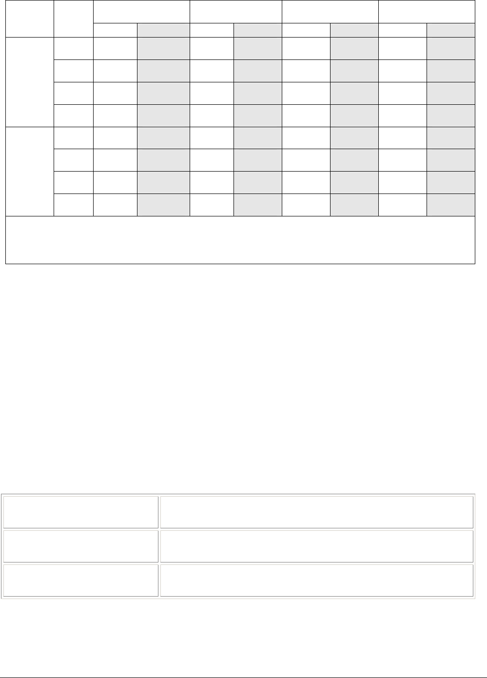
The following tables show calculated ranges with a link budget of 10 dB (fading margin) and unlimited
clearance. The clearance is the average antenna height; it also incorporates earth bulge. Lower link budget
results in longer links, but less reliable communication.
On very short links, the link budget can be lower than 10 dB, while at longer links more fading occurs and a high
fading margin is needed.
24 dBi Directional Parabolic
Grid Antenna* 14 dBi Directional
Antenna 12 dBi Directional Wide
Angle Antenna
Antenna
Antenna
Speed
Mbps Range Clearance Range Clearance Range Clearance
1 112 km
70 mi
285 m
936 ft
35 km
22 mi
47 m
156 ft
28 km
17 mi
36 m
118 ft
2 79 km
49 mi
157 m
515 ft
25 km
16 mi
32 m
104 ft
20 km
12 mi
25 m
82 ft
5.5 50 km
31 mi
76 m
250 ft
16 km
9.8 mi
20 m
67 ft
13 km
7.8 mi
17 m
55 ft
24 dBi Directional
Parabolic Grid Antenna
11 28 km
17 mi
36 m
118 ft
8.9 km
5.5 mi
13 m
43 ft
7.1 km
4.4 mi
11 m
37 ft
1 35 km
22 mi
47 m
156 ft
11 km
7.0 mi
15 m
51 ft
8.9 km
5.5 mi
13 m
43 ft
2 25 km
16 mi
32 m
104 ft
7.9 km
4.9 mi
12 m
40 ft
6.3 km
3.9 mi
10 m
34 ft
5.5 16 km
9.8 mi
20 m
67 ft
5.0 km
3.1 mi
9.2 m
30 ft
4.0 km
2.5 mi
8.0 m
26 ft
14 dBi Directional Antenna
11 8.9 km
5.5 mi
13 m
43 ft
2.8 km
1.8 mi
6.7 m
22 ft
2.2 km
1.4 mi
5.9 m
19 ft
1 29 km
18 mi
38 m
124 ft
9.3 km
5.8 mi
14 m
44 ft
7.4 km
4.6 mi
12 m
38 ft
2 21 km
13 mi
26 m
86 ft
6.6 km
4.1 mi
11 m
35 ft
5.2 km
3.3 mi
9.4 m
31 ft
5.5 13 km
8.2 mi
17 m
57 ft
4.2 km
2.6 mi
8.2 m
27 ft
3.3 km
2.1 mi
7.3 m
24 ft
12 dBi Directional Window
Antenna
11 7.4 km
4.6 mi
12 m
38 ft
2.3 km
1.5 mi
6.0 m
20 ft
1.9 km
1.2 mi
5.3 m
18 ft
*The maximum range for the 24 dBi Grid antennas is a calculated value. Maximum ranges were only tested up to 110 km.
Values in this table are based upon the use of normal power Tsunami MP.11 and 6m (20 ft) low-loss antenna cables with a diameter of 10 mm (0.4 in)
on both ends of the antenna link, except the Window Antenna which is connected by the attached 2m (6 ft) cable.
Table 1. Maximum Outdoor Range for FCC Products, Part 1
Chapter 2. Determining Range and Clearance 22

Tsunami MP.11 Antenna Installation Guide
10 dBi Omni-Directional Base
Station Antenna 7 dBi Omni-Directional
Base Station Antenna
Antenna
Antenna
Speed
Mbps Range Clearance Range Clearance
1 22 km
14 mi
28 m
92 ft
17 km
11 mi
22 m
71 ft
2 16 km
9.8 mi
20 m
67 ft
12 km
7.5 mi
16 m
54 ft
5.5 10 km
6.2 mi
14 m
46 ft
7.7 km
4.8 mi
12 m
40 ft
24 dBi Directional Parabolic Grid
Antenna
11 5.6 km
3.5 mi
9.8 m
32 ft
4.3 km
2.7 mi
8.4 m
28 ft
1 7.1 km
4.4 mi
11 m
37 ft
5.4 km
3.4 mi
9.6 m
31 ft
2 5.0 km
3.1 mi
9.1 m
30 ft
3.8 km
2.4 mi
7.9 m
26 ft
5.5 3.2 km
2.0 mi
7.1 m
23 ft
2.4 km
1.5 mi
6.3 m
20 ft
14 dBi Directional Antenna
11 1.8 km
1.1 mi
5.2 m
17 ft
1.4 km
0.8 mi
4.6 m
15 ft
1 5.9 km
3.6 mi
10 m
33 ft
4.5 km
2.8 mi
8.6 m
28.3 ft
2 4.2 km
2.6 mi
8.2 m
27 ft
3.2 km
2.0 mi
7.1 m
23.3 ft
5.5 2.6 km
1.6 mi
6.4 m
21 ft
2.0 km
1.3 mi
5.6 m
18.3 ft
12 dBi Directional Window
Antenna
11 1.5 km
0.9 mi
4.7 m
16 ft
1.1 km
0.7 mi
4.1 m
13.6 ft
Values in this table are based upon the use of normal power Tsunami MP.11 and 6m (20 ft) low-loss antenna cables with a diameter of 10 mm (0.4
in) on both ends of the antenna link, except the Window Antenna which is connected by the attached 2m (6 ft) cable.
Table 2. Maximum Outdoor Range for FCC Products, Part 2
Chapter 2. Determining Range and Clearance 23
Tsunami MP.11 Antenna Installation Guide
14 dBi Directional
Antenna1 12 dBi Directional
Wide Angle Antenna1 10 dBi Omni-Directional
Base Station Antenna1 7 dBi Omni-Directional
Base Station Antenna2
Antenna
Speed
Mbps Range Clearance Range Clearance Range Clearance Range Clearance
1 5.0 km
3.1 mi
9.1 m
30.0 ft
4.0 km
2.5 mi
8.0 m
26.3 ft
3.2 km
2.0 mi
7.1 m
23.2 ft
2.4 km
1.5 mi
6.1 m
20.1 ft
2 3.5 km
2.2 mi
7.5 m
24.7 ft
2.8 km
1.7 mi
6.6 m
21.8 ft
2.2 km
1.4 mi
5.9 m
19.3 ft
1.7 km
1.1 mi
5.1 m
16.8 ft
5.5 2.2 km
1.4 mi
5.9 m
19.3 ft
1.8 km
1.1 mi
5.2 m
17.1 ft
1.4 km
0.9 mi
4.6 m
15.2 ft
1.1 km
0.7 mi
4.0 m
13.3 ft
14 dBi
Directional
Antenna
11 1.3 km
0.8 mi
4.4 m
14.3 ft
1.0 km
0.6 mi
3.9 m
12.7 ft
0.8 km
0.5 mi
3.5 m
11.3 ft
0.6 km
0.4 mi
3.0 m
9.9 ft
1 4.2 km
2.6 mi
8.2 m
27.0 ft
3.3 km
2.1 mi
7.3 m
23.8 ft
2.6 km
1.6 mi
6.4 m
21.0 ft
2.0 km
1.3 mi
5.6 m
18.3 ft
2 2.9 km
1.8 mi
6.8 m
22.3 ft
2.3 km
1.5 mi
6.0 m
19.8 ft
1.9 km
1.2 mi
5.3 m
17.5 ft
1.4 km
0.9 mi
4.7 m
15.3 ft
5.5 1.9 km
1.2 mi
5.3 m
17.5 ft
1.5 km
0.9 mi
4.7 m
15.6 ft
1.2 km
0.7 mi
4.2 m
13.8 ft
0.9 km
0.6 mi
3.7 m
12.1 ft
12 dBi
Directional
Window
Antenna
11 1.0 km
0.6 mi
4.0 m
13.1 ft
0.8 km
0.5 mi
3.5 m
11.6 ft
0.7 km
0.4 mi
3.2 m
10.3 ft
0.5 km
0.3 mi
2.8 m
9.0 ft
1Values in this table are based upon the use of low power Tsunami MP.11 and 6m (20 ft) low-loss antenna cables with a diameter of 10 mm (0.4 in) on
both ends of the antenna link, except the Window Antenna which is connected by the attached 2m (6 ft) cable.
2Values in the table for the 7 dBi omni antenna are limited by the use of the low power Tsunami MP.11 at the side of the directional antenna. The 6m
(20 ft) low-loss antenna cables with a diameter of 10 mm (0.4 in) are used on both ends of the antenna link, except with the Window Antenna which is
connected by the attached 2m (6 ft) cable.
Table 3. Maximum Range for ETSI/FR/JP Products
DISTANCE ASSUMPTIONS AND EXPECTATIONS
Indoor Tsunami MP.11a
Assumptions
▪ Point-to-multipoint configuration using USA regulations for L and U bands, ETSI regulations for M bands
▪ Clear line-of-sight with no unusual multipath
▪ Sector antenna (17 dBi, 60º) at Base Station with 20 feet LMR-600 cable
▪ Three-foot parabolic dish (31.4 dBi) at Subscriber Unit with 20-foot LMR-600 cable
▪ With a fade margin minimum of 10 dB to 2 miles, and 0.2 dB additional fade margin for every 0.1 miles, to
15 dB, availability is greater than 99.99%.
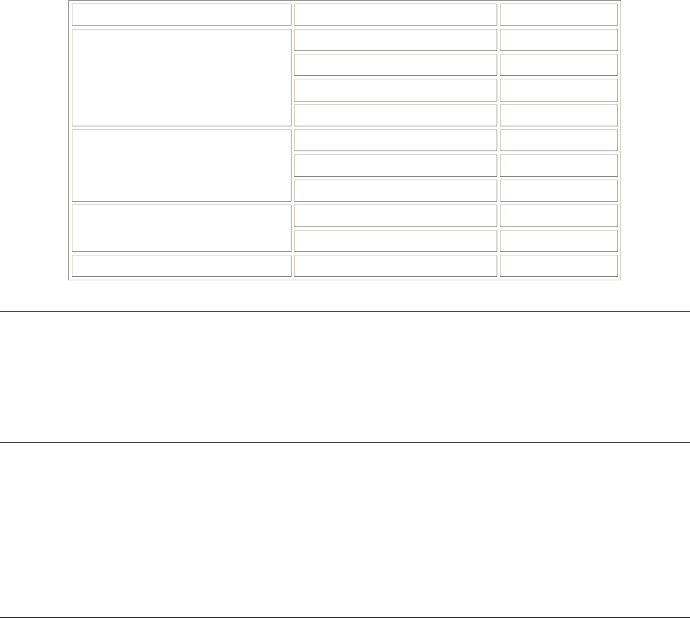
Expectations
5.25 – 5.35 GHz 0.9 miles at peak performance (36 Mbps mode)
Up to 2.8 miles maximum (6 Mbps mode)
5.47 – 5.725 GHz 0.85 miles at peak performance (36 Mbps mode)
Up to 2.65 miles maximum (6 Mbps mode)
5.725 – 5.850 MHz 4.0 miles at peak performance (36 Mbps mode)
Up to 11.2 miles maximum (6 Mbps mode)
Chapter 2. Determining Range and Clearance 24

Tsunami MP.11 Antenna Installation Guide
Outdoor Tsunami MP.11a
Assumptions
▪ Point-to-multipoint configuration using USA regulations for L and U bands, ETSI regulations for M bands
▪ Clear line-of-sight with no unusual multipath
▪ Sector antenna (17 dBi, 60º) at Base Station with short 1 dB jumper cable
▪ Standard integrated antenna for Subscriber Unit
▪ With a fade margin minimum of 10 dB to 2 miles, and 0.2 dB additional fade margin for every 0.1 miles, to
15 dB, availability is greater than 99.99%.
Expectations
5.25 – 5.35 GHz 0.5 miles at peak performance (36 Mbps mode)
Up to 1.7 miles maximum (6 Mbps mode)
5.47 – 5.725 GHz 0.4 miles at peak performance (36 Mbps mode)
Up to 1.6 miles maximum (6 Mbps mode)
5.725 – 5.850 MHz 2.8 miles at peak performance (36 Mbps mode)
Up to 7.6 miles maximum (6 Mbps mode)
MP.11
Assumptions
▪ Point-to-multipoint configuration using USA regulations for L and U bands, ETSI regulations for M bands
▪ Clear line-of-sight with no unusual multipath
▪ Sector antenna (17 dBi, 60º) at Base Station with 20-foot LMR-600 cable
▪ Three-foot parabolic dish (31.4 dBi) at Subscriber Unit with 20-foot LMR-600 cable for USA
▪ 14 dBi panel antenna at Subscriber Unit with 20-foot LMR-600 cable for ETSI
▪ With a fade margin minimum of 10 dB to 2 miles, and 0.2 dB additional fade margin for every 0.1 miles, to
15 dB, availability is greater than 99.99%.
Expectations
6.8 miles at peak performance (11 Mbps) for FCC
0.9 miles at peak performance (11 Mbps) for ETSI
Up to 1.73 miles maximum (1 Mbps) for FCC
Up to 3 miles maximum (1 Mbps) for ETSI
Chapter 2. Determining Range and Clearance 25
Tsunami MP.11 Antenna Installation Guide
DATA SPEED OF THE WIRELESS LINK
By default, the family of Tsunami MP.11 products transmits at the highest available transmit rate.
Because data transmissions at lower speeds can travel greater distances than transmissions at the highest
transmit rate, the system lets you choose a lower data rate to increase the maximum range. For information
about customizing the transmit rate of your system, consult the Tsunami MP.11/a Installation and Management
manual.
To assist you in determining the appropriate tuning settings, we have listed the range values that apply to the
various transmit rates in Tables 1, 2, and 3.
CABLE FACTOR
The range value calculations listed in Table 1 on page 22 and Table 2 on page 23 were based upon antenna
installations in which both antennas were connected to a 6 m (20 ft) cable.
If this is the case in your situation, the Cable Factor for your installation is 100%.
If you are using different cables, you must determine the Cable Factor from Table 4 below to calculate the
probable range for your installation.
One side of link Other side of link Cable Factor
6 m (20 ft) / 10 mm (0.4 in) 100%
6 m (20 ft) / 5 mm (0.2 in) 81%
15 m (50 ft) 81%
6 m (20 ft) / 10 mm (0.4 in)
22 m (75 ft) 67%
6 m (20 ft) / 5 mm (0.2 in) 66%
15 m (50 ft) 66%
6 m (20 ft) / 5 mm (0.2 in)
22 m (75 ft) 54%
15 m (50 ft) 66% 15 m (50 ft)
22 m (75 ft) 54%
22 m (75 ft) 22 m (75 ft) 45%
Table 4. Cable Factor
Note: When Table 4 is used for countries that adhere to the ETSI regulations, note that the maximum ranges
as listed in Table 3 do not always use cable factor 100%. This is due to local radio regulations and
legislation that do not allow the use of the 6 m (20 ft)/10 mm (0.4 in) cables in ETSI countries France
and Japan.
The 6 m (20 ft) cables with a diameter of 5 mm (0.2 in) can be used with all antenna types. The cable
loss of these cables equals the value of the 15 m (50 ft) cables. Use of the 6 m (20 ft) cables with a
diameter of 10 mm (0.4 in) depends upon local radio regulations.
Chapter 2. Determining Range and Clearance 26
Tsunami MP.11 Antenna Installation Guide
CLEARANCE FACTOR
For optimal performance of your outdoor wireless link, the signal path between the two Base Unit and
Subscriber Unit must provide sufficient clearance.
Note: An outdoor wireless link that lacks sufficient clearance can suffer from poor performance, which is
typically perceived as slow network response times. Although your Tsunami MP.11 equipment
automatically retransmits every lost data frame due to an out-of-range situation or frame collision, the
larger the number of retransmissions, the lower the throughput efficiency of your wireless link.
This section explains how to determine the clearance that applies in your environment and (if applicable) the
effect of insufficient clearance on the range of your outdoor wireless link.
In “Chapter 1. Preparing for Installation” on page 8, we described the shape of the antenna beam as being
“bulged” in the middle.
Figure 3. Fresnel Zone
If any significant part of this bulged zone is obstructed, a portion of the radio energy is lost, which can affect the
performance of your wireless link in terms of maximum range and transmit rate.
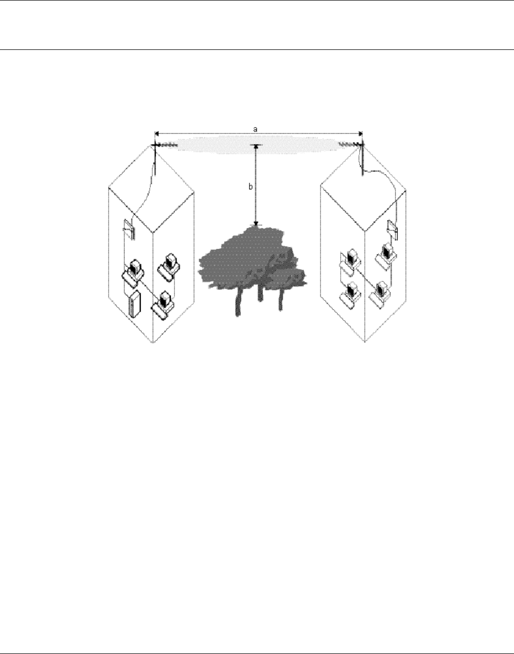
In Figure 3, you see two variables that determine the shape of the antenna beam, also referred to as Fresnel
Zone:
a. The distance between the antennas
b. The clearance required for optimal performance, where clearance should be interpreted as:
º Vertical clearance above the ground and the highest buildings or objects in the signal path
º Horizontal clearance from neighboring buildings and objects in the signal path.
For optimal range and throughput performance, you must ensure that your antenna installation provides
maximum clearance in both horizontal and vertical direction.
The minimum clearance for the various antenna combinations and distances is listed in the gray-shaded
columns of Tables 1 and 2, where clearance should be interpreted as follows:
▪ In open areas without obstacles in the signal path, clearance is measured as height above the surface of the
earth. For example, if the antenna is mounted on the roof, this height includes the height of the building plus
the height of the mast above the rooftop.
Chapter 2. Determining Range and Clearance 27
Tsunami MP.11 Antenna Installation Guide
▪ In areas with obstacles in the signal path between the two antennas, clearance should be measured as
height above the highest obstacle in the signal path.
▪ In dense urban areas, the clearance should be measured as height above the highest rooftop or any other
obstacles in the signal path between the two antennas.
Looking at the minimum clearance requirements as identified in Table 1 on page 22 and Table 2 on page 23, it
may be that local authorities, the proprietor of the premises, or other reasons may prevent you from setting up
an antenna mast that lets you meet the listed clearance requirement.
In such situations, you may be unable to achieve a full line-of-sight clearance. At the same time, however, you
may not even need full clearance, when the distance that your wireless outdoor installation must cover is less
than the listed maximum range.
To determine the effect of insufficient signal path clearance, you must determine the Clearance Factor as
described below, and calculate its effect on the range for your antenna installation using the formula described in
“Determining the Outdoor Range” on page 20.
▪ If the clearance for your antenna installation is equal to or better than the minimum clearance requirement
identified in Tables 1, 2, and 3, the Clearance Factor for your installation is 100%.
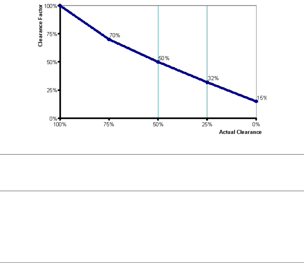
▪ If your actual clearance is less than the minimum clearance identified in Tables 1, 2, and 3, you should use
the diagram depicted in the following figure to determine the actual range that applies in your situation.
Figure 4. Clearance Factor Diagram
Note: Use the Clearance Factor diagram as a rule-of-thumb for estimating the probable range in case the
clearance requirements are not fully met. In real life, using FCC-approved products, it is almost
impossible to achieve the level of clearance for maximum range. For your convenience, we have
included Table 5 on page 29 and Table 6 on page 30 to provide an example of conditions in which the
more typical clearance is 10 m (33 ft).
Chapter 2. Determining Range and Clearance 28

Tsunami MP.11 Antenna Installation Guide
24 dBi Directional Parabolic
Grid Antenna 14 dBi Directional
Antenna 12 dBi Directional Wide
Angle Antenna
Antenna
Antenna
Speed
Mbps Range Clearance Range Clearance Range Clearance
1 26.2 km
16.3 mi
10 m
33 ft
19.0 km
11.8 mi
10 m
33 ft
17.3 km
10.7 mi
10 m
33 ft
2 24.5 km
15.2 mi
10 m
33 ft
16.9 km
10.5 mi
10 m
33 ft
15.4 km
9.6 mi
10 m
33 ft
5.5 21.8 km
13.5 mi
10 m
33 ft
14.4 km
8.9 mi
10 m
33 ft
13.1 km
8.1 mi
10 m
33 ft
24 dBi Directional Parabolic
Grid Antenna
11 19.4 km
12.0 mi
10 m
33 ft
12.8 km
8.0 mi
10 m
33 ft
11.2 km
7.0 mi
10 m
33 ft
1 19.0 km
11.8 mi
10 m
33 ft
12.0 km
7.5 mi
10 m
33 ft
10.9 km
6.8 mi
10 m
33 ft
2 16.9 km
10.5 mi
10 m
33 ft
10.2 km
6.3 mi
10 m
33 ft
9.3 km
5.8 mi
10 m
33 ft
5.5 14.4 km
8.9 mi
10 m
33 ft
8.7 km
5.4 mi
10 m
33 ft
7.6 km
4.7 mi
10 m
33 ft
14 dBi Directional Antenna
11 12.8 km
8.0 mi
10 m
33 ft
7.1 km
4.4 mi
10 m
33 ft
6.1 km
3.8 mi
10 m
33 ft
1 17.3 km
10.7 mi
10 m
33 ft
10.9 km
6.8 mi
10 m
33 ft
10.9 km
6.8 mi
10 m
33 ft
2 15.4 km
9.6 mi
10 m
33 ft
9.3 km
5.8 mi
10 m
33 ft
8.2 km
5.1 mi
10 m
33 ft
5.5 13.1 km
8.1 mi
10 m
33 ft
7.6 km
4.7 mi
10 m
33 ft
6.7 km
4.2 mi
10 m
33 ft
12 dBi Directional Window
Antenna
11 11.2 km
7.0 mi
10 m
33 ft
6.1 km
3.8 mi
10 m
33 ft
5.4 km
3.3 mi
9.5 m
31 ft
Table 5. FCC Outdoor Range with 10 m 933 ft) Clearance, Part 1
Chapter 2. Determining Range and Clearance 29

Tsunami MP.11 Antenna Installation Guide
10 dBi Omni-Directional Base
Station Antenna 7 dBi Omni-Directional
Base Station Antenna
Antenna
Antenna
Speed
Mbps Range Clearance Range Clearance
1 15.8 km
9.8 mi
10 m
33 ft
14.1 km
8.8 mi
10 m
33 ft
2 14.1 km
8.8 mi
10 m
33 ft
12.0 km
7.5 mi
10 m
33 ft
5.5 12.0 km
7.5 mi
10 m
33 ft
10.2 km
6.3 mi
10 m
33 ft
24 dBi Directional Parabolic Grid
Antenna
11 10.2 km
6.3 mi
10 m
33 ft
8.7 km
5.4 mi
10 m
33 ft
1 9.5 km
5.9 mi
10 m
33 ft
8.1 km
5.0 mi
10 m
33 ft
2 8.1 km
5.0 mi
10 m
33 ft
6.6 km
4.1 mi
10 m
33 ft
5.5 6.6 km
4.1 mi
10 m
33 ft
5.5 km
3.4 mi
10 m
33 ft
14 dBi Directional Antenna
11 5.5 km
3.4 mi
10 m
33 ft
4.0 km
2.5 mi
10 m
33 ft
1 km
mi
10 m
33 ft
km
mi
10m
33 ft
2 km
mi
10 m
33 ft
km
mi
10 m
33 ft
5.5 km
mi
10 m
33 ft
km
mi
10 m
33 ft
12 dBi Directional Antenna
11 km
mi
10 m
33 ft
km
mi
10 m
33 ft
Table 6. FCC Outdoor Range with 10 m 933 ft) Clearance, Part 2
Chapter 2. Determining Range and Clearance 30
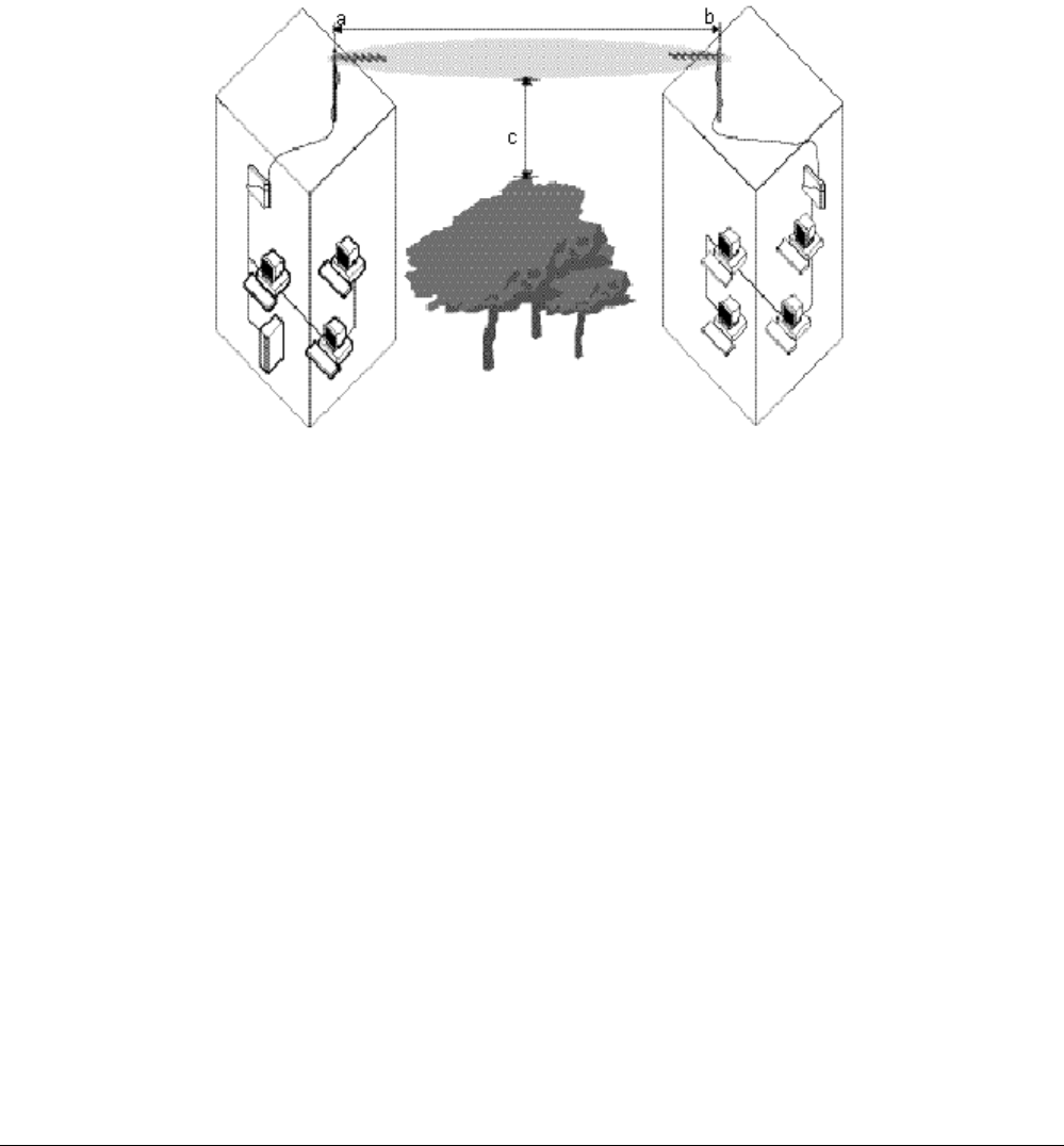
Tsunami MP.11 Antenna Installation Guide
EXAMPLES
In the following sections, you find some examples of range and clearance calculations for point-to-point links
and for a point-to-multipoint network.
Point-to-Point Links
Suppose you are installing a wireless point-to-point link between a Base Unit and a Subscriber Unit, where:
▪ Both sites have been equipped with a 24 dBi Directional Parabolic Grid Antenna, connected via 6 m (20
ft)/10 mm antenna cables.
▪ The distance between site a and site b is 25 km (15.3 mi).
▪ The site is located in the US, which allows the use of FCC approved equipment.
Figure 5. Calculating Point-to-Point Range
Looking at Table 1, we learn that a high speed link between two 24 dBi Directional Grid Antennas may cover a
maximum distance of 85 km (52 mi), provided that the signal path clearance is 180 m (590 ft) or better.
The probable range for this example can be calculated using the introduced formula:
Range = Maximum Range x Cable Factor x Clearance Factor
Calculating the Clearance Affect on Range
In the example depicted in Figure 5, we see a set of trees in the signal path. Suppose that the clearance (c)
between these trees and the signal path is only be 45 m (148 ft).
▪ Using a calculator, we can easily determine that this 45 m (148 ft) is about 25% of the required 180 m (590
ft) clearance for maximum range.
▪ Looking at the “Clearance Factor Diagram,” we can see that 25% actual clearance equals a Clearance
Factor of 32%.
▪ If we apply this Clearance Factor to the range calculation formula, your probable range would become:
Range = 85 km (52 mi) x 32% x 100% = 27.2 km (16.6 mi)
This might satisfy your requirements for high-speed data transmissions between the two units. However, this
range is very close to the required range of 25 km. The margin should be higher to deal with bad weather
conditions.
Chapter 2. Determining Range and Clearance 31

Tsunami MP.11 Antenna Installation Guide
If we base the calculation on transmissions at medium speed, your range calculation would look as follows:
▪ Looking at Table 1, we learn that a medium speed link between two 24 dBi directional parabolic grid
antennas may cover a maximum distance of 120 km (74 mi), provided the signal path clearance is 320 m
(1050 ft).
▪ As mentioned above however, our actual clearance is only 45 m (148 ft); 14% of the required 320 m (1050
ft).
Range = 120 km (74 mi) x 25% x 100% = 30 km (18.6 mi)
This result indicates that you have a better margin and can set the transmit rate of your system to medium
speed for reliable wireless communications.
Optionally, you can run Link Test to determine whether the high-speed option might provide reliable wireless
links as well.
Calculating the Cable Affect on Range
We presumed that the antennas were connected by 6 m (20 ft) cables with a diameter of 10 mm (0.4 in) at both
sites.
If we replaced this cable at building b with a longer 22 m (75 ft) cable, we must look at the Cable Factor effect of
this longer cable.
Table 4 tells us that this new cabling combination would result in a Cable Factor of 67%.
If we apply this Cable Factor to the range calculation formula again, the probable range would become:
Range = 120 km (74 mi) x 25% x 67% = 20.1 km (12.5 mi)
This result indicates that the effect of this cable can prevent your wireless link from operating at both high and
medium speed. In such situations you are advised to:
▪ Relocate the unit to a location that lets you use a shorter cable length.
▪ Increase the height of the antenna on the mast, or install taller antenna masts, to increase the signal path
clearance.
▪ Trade-off data speed versus range and recalculate the ranges that could be achieved at lower transmit
rates.
Alternatively, you can perform on-site diagnostic measurements to validate the results of this calculation.
Consult the Tsunami MP.11/a Installation and Management manual for information about using the Link Test
feature to perform on-site diagnostic measurements.
Chapter 2. Determining Range and Clearance 32
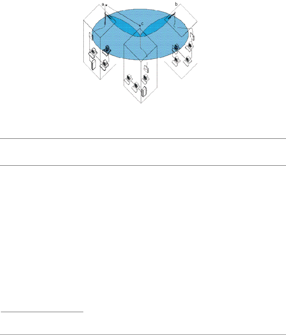
Tsunami MP.11 Antenna Installation Guide
Point-to-Multipoint Network
Suppose you are installing a wireless point-to-multipoint network between one Base Unit and two Subscriber
Units, as shown in the following figure, where:
▪ The Base Unit in building c is connected to a 7 dBi Omni-Directional Base Unit Antenna
▪ The two remote sites a and b have been equipped with a 14 dBi Directional Antenna
▪ All sites have been connected via 15 m (50 ft) antenna cables
▪ The site is located in the Europe, which requires you to use ETSI approved equipment3.
Figure 6. Calculating Point-to-Multipoint Range
For this type of outdoor antenna installation, you must determine the range for each link individually; that is, the
range from building c to building a, and from building c to building b.
Note: In this example we demonstrate only the calculation for the link between building a and c; however, as
different clearance factors may apply for each of these links, you are advised to calculate the actual
range for each link individually when designing a “real” outdoor wireless link.
In this example we assume that:
▪ The antenna installation is to be installed in a dense urban area, where the distance between building a and
building c is 0.5 km (0.3 mi).
▪ The actual clearance is 3 m (9.9 ft), being the height of the antennas on the mast.
The probable range for this example can be calculated using the introduced formula:
Range = Maximum Range x Cable Factor x Clearance Factor
Looking at Table 3, we learn that a high-speed link between a 7 dBi Omni-Directional Base Unit Antenna and a
14 dBi Directional Antenna may cover a maximum distance of 1.4 km (0.9 mi), provided the signal path
clearance is 5.6 m (18 ft) or better.
Using a calculator, we can easily determine that the actual clearance of 3 m (9.9 ft) is about 75% of the required
5.6 m (18 ft), which equals a Clearance Factor of 70% (see Figure 5).
The maximum range calculation in Table 2 was based on the use of:
▪ 6 m (20 ft) cables with a diameter of 5 mm (0.2 in) for the site with the 14 dBi Directional Antenna
▪ 6 m (20 ft) cables with a diameter of 10 mm (0.4 in) for the 7 dBi Omni-Directional Base Unit Antenna.
3In France you may only use equipment based on the FR channel-set.
Chapter 2. Determining Range and Clearance 33

Tsunami MP.11 Antenna Installation Guide
In other words, the Cable Factor for the maximum range calculation, already represents a value of 81%.
However, because the site as depicted in Figure 3 actually is using two 15 m (50 ft) cables, Table 3 identifies the
Cable Factor as being 66%.
Your actual Cable Factor is 66% Cable Factor divided by the maximum range cable factor: 66% ÷ 81% = 81%.
If we import all this information into the range calculation formula, your probable range for high-speed
transmissions would become:
Range = 1.4 km (0.9 mi) x 70% x (66% ÷ 81%) = 0.8 km (0.5 mi)
For campus type environments, this range is probably sufficient to connect multiple buildings; however, if you
must cover a larger distance, you can either:
▪ Relocate the unit to a location that lets you use a shorter cable length.
▪ Increase the height of the antenna on the mast or install taller antenna masts to increase the signal path
clearance.
▪ Trade-off data speed versus range and recalculate the ranges that could be achieved at lower transmit
rates.
Alternatively, you may decide to perform on-site diagnostic measurements to validate the results of this
calculation. Consult the documentation that comes with the Tsunami MP.11 for information about using the Link
Test feature to perform on-site diagnostic measurements.
Chapter 2. Determining Range and Clearance 34

Tsunami MP.11 Antenna Installation Guide
Chapter 3. Antenna Cabling System
SELECTING THE CORRECT CABLES
To comply with local radio regulations, Proxim Corporation offers two types of Base and Subscriber unit that can
be used to connect to an outdoor antenna installation: A 15 dBm Transmit power system and an 8 dBm
Transmit power system
The low-loss antenna cables are also available in various lengths and diameters:
▪ 6 m (15 ft) with a diameter of 5 mm (0.2 in) (The cable-loss of this cable equals the loss of the 15 m (50 ft)
cable.)
▪ 6 m (15 ft) with a diameter of 10 mm (0.4 in)
▪ 15 m (50 ft) with a diameter of 10 mm (0.4 in)
▪ 22 m (75 ft) with a diameter of 10 mm (0.4 in)
When you order the Tsunami MP.11 antenna equipment, make sure that you order cables that comply with the
regulations that apply in your country. In case of doubt, consult the Proxim Corporation Sales office for more
information.
ETSI Regulated Countries
The 24 dBi Directional Parabolic Grid Antenna is not allowed in ETSI countries, such as France.
All other antennas and all channels 1...13 are allowed in ETSI countries, with some exceptions. Check the
regulatory information to find the allowed channels in a specific region.
FCC Regulated Countries
Antenna Cable Type
Antenna 6 m (20 ft)
5 mm (0.2 in) 6 m (20 ft)
10 mm (0.4 in) 15 m (50 ft)
10 mm (0.4 in) 25 m (75 ft)
10 mm (0.4 in)
7 dBi Omni-Directional Base Station Antenna Yes Yes Yes Yes
10 dBi Omni-Directional Base Station Antenna Yes Yes Yes Yes
12 dBi Directional Wide Angle Antenna Yes Yes Yes Yes
14 dBi Directional Antenna Yes Yes Yes Yes
24 dBi Directional Parabolic Grid Antenna* Yes Yes Yes Yes
* consult the following table for restrictions on channel selection
Table 7. Certified Cable and Antenna Combinations FCC
Chapter 3. Antenna Cabling System 35

Tsunami MP.11 Antenna Installation Guide
Frequency Channels
Antenna 1 2 3 4 5 6 7 8 9 10 11
7dBi Omni-Directional Base
Station Antenna
Yes Yes Yes Yes Yes Yes Yes Yes Yes Yes Yes
10 dBi Omni-Directional Base
Station Antenna
Yes Yes Yes Yes Yes Yes Yes Yes Yes Yes Yes
12 dBi Directional Wide Angle
Antenna
Yes Yes Yes Yes Yes Yes Yes Yes Yes Yes Yes
14 dBi Directional Antenna Yes Yes Yes Yes Yes Yes Yes Yes Yes Yes Yes
24 dBi Directional Parabolic Grid
Antenna
No No Yes Yes Yes Yes Yes Yes Yes No No
Table 8. Certified Channel and Antenna Combinations FCC
Japanese Regulated Country
The use of a Directional Antenna is not allowed in channel 14 in Japan.
REGULATORY INFORMATION
The Tsunami outdoor antenna solution must be installed and used in strict accordance with the instructions as
described in this Tsunami Outdoor Antenna Installation Guide.
Note: Radio approvals for the Tsunami outdoor antenna solution are valid only when using the exact
combination of outdoor antenna cabling components and antennas as listed in this Tsunami MP.11
Antenna Installation Guide.
Using other combinations of parts and components in outdoor antenna solutions voids the radio type
approval and may be in violation of local radio regulations.
Proxim Corporation and its authorized resellers or distributors are not liable for any damage or violation of
government regulations that may arise from failing to comply with these guidelines.
Chapter 3. Antenna Cabling System 36
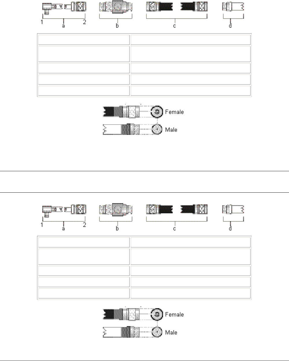
Tsunami MP.11 Antenna Installation Guide
SELECTING THE CORRECT CONNECTOR TYPE
All cabling components of the Tsunami outdoor antenna system come with standard-N type connectors as
depicted in the following table.
Cabling Component Standard-N Cabling Systems
a Pigtail attached to MP.11 1 Proprietary connector
2 Stand-N male
b Surge arrestor Reverse polarity-N female on both ends
c Low-loss cable Reverse Polarity-N male on both ends
d Outdoor antenna Reverse polarity-N female
Table 9. Standard N-Type Connector Diagram
Note that the gender of the connector is not determined by the connector’s thread, but by its center pin; a solid
center pin = male, a hollow pin = female.
Note: Previously marketed Tsunami outdoor antenna systems in FCC regulated countries (such as the USA
and Canada) were shipped with a different cabling system, identified by reverse polarity-N connectors
(depicted in the following table).
Cabling Component Reverse Polarity-N Cabling Systems
a Pigtail attached to MP.11 1 Proprietary connector
2 Reverse polarity-N male
b Surge arrestor Reverse polarity-N female on both ends
c Low-loss cable Reverse Polarity-N male on both ends
d Outdoor antenna Reverse polarity-N female
Table 10. Reverse Polarity-N Cabling Diagram
Chapter 3. Antenna Cabling System 37

Tsunami MP.11 Antenna Installation Guide
Note that the gender of the connector is not determined by the connector’s thread, but by its center pin; a solid
center pin = male, a hollow pin = female.
DANGER!
Outdoor antennas and antenna cables are electrical conductors. Transients or electrostatic discharges
that may occur at the antenna (for example a lightning strike during thunderstorms) may damage your
electronic equipment and cause personal injury or death to persons touching the exposed metal
connectors of the antenna cable.
To avoid damage and personal injury, the entire antenna cabling system must be grounded at all times.
When installing, disconnecting, or replacing one of the cabling components, ensure at all times that
each exposed antenna cabling system metal connector is grounded locally during the work.
For example when mounting or replacing the surge arrestor:
1. First connect each of the connectors of the low-loss antenna cables to the grounding system.
2. Next connect the cable connector to the grounding system.
3. Finally connect the surge arrestor to the grounding system.
Before you proceed, verify that each of the items is properly grounded and that the ground is not interrupted
when disconnecting one of the antenna system components.
Check with a qualified electrician if you are in doubt whether the surge arrestor and cable connectors are
properly grounded.
Only after you have verified that each of the items is properly grounded, replace the surge arrestor and
disconnect the cables from the grounding system in exactly the reverse order of the previous steps.
Chapter 3. Antenna Cabling System 38
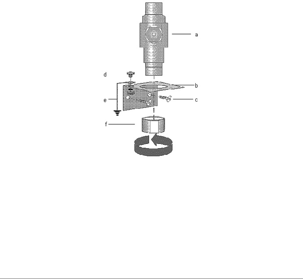
Tsunami MP.11 Antenna Installation Guide
OUTDOOR CABLING COMPONENTS
To connect your Tsunami MP.11 hardware to an outdoor antenna installation, the following cabling components
are required:
▪ Surge arrestor
▪ Low-loss antenna cables
▪ One of the outdoor antennas described “Chapter 4. Recommended Antennas” on page 41.
When purchasing new Tsunami MP.11 products, each of these components is equipped with standard N-type
connectors.
When ordering separate components, for example as a spare part or replacement to previously purchased
Tsunami outdoor antenna equipment, carefully read the note on the following page to ensure that you order
components with an N-type connector that matches the other parts of your outdoor antenna cabling system.
Surge Arrestor
The surge arrestor (sometimes referred to as a lightning protector) can protect your sensitive outdoor router
equipment from high-voltage surges caused by discharges and transients at the antenna.
Figure 7. Surge Arrestor
To mount the surge arrestor:
1. Determine a suitable location for the bracket (item b) as described in “Chapter 1. Preparing for Installation.”
2. Use the screws (item c) to attach the bracket to the wall.
3. Apply a ring-terminal to the ground wire. Use the bolt, lock-washer, and nut (item d) to connect the ground
wire (item e) to the mounting bracket.
Chapter 3. Antenna Cabling System 39

Tsunami MP.11 Antenna Installation Guide
4. The ring-terminal and ground wire are not included, but must be installed by a certified electrician familiar
with national electricity and safety codes, according to the instructions described in “Grounding the Antenna”
on page 16.
5. Insert the surge arrestor (item a) into the bracket as depicted in the preceding figure.
6. Use the hex-nut (item f) to secure the surge arrestor in its position. Ensure that the surge arrestor is
properly connected to the grounding system.
CAUTION!
To avoid damage to electronic equipment and your Tsunami MP.11 equipment always apply the surge
arrestor between the outdoor antenna installation and the Tsunami MP.11 hardware or other computing
device that is connected to the outdoor antennas.
See “Surge Protector“ on page 71 for surge protector specifications.
Low-Loss Antenna Cable
The low-loss antenna cable is available in three standard lengths:
▪ 6 m (20 ft)
▪ 15 m (50 ft)
▪ 22 m (75 ft)
To ensure that you order the right cable length, determine the distance between the intended locations of the
Tsunami MP.11 hardware and outdoor antenna carefully.
See “LMR 600 Cable” on page 73 for cable specifications.
Chapter 3. Antenna Cabling System 40

Tsunami MP.11 Antenna Installation Guide
Chapter 4. Recommended Antennas
TYPE OF OUTDOOR ANTENNA EQUIPMENT
As described previously, Proxim Corporation offers different types of outdoor antennas and cable lengths for
your network design.
The directional antennas provide maximum range, but due to their narrow beamwidth, these antennas require
precise antenna alignment to achieve optimal performance. The higher the antenna gain, the more precise the
alignment should be. Directional antennas are typically used to connect:
▪ A Base Unit and a Subscriber Unit in a point-to-point link
▪ A Subscriber Unit in a point-to-multipoint network
The omni-directional antennas have, by nature, an omni-directional azimuth pattern that makes them easy to
install. There is also a gain beamwidth relation for omni-antennas: The higher the gain of the omni-antenna, the
narrower the vertical beamwidth. In a hilly terrain, a 7dBi omni-directional antenna can be a better solution than
the 10 dBi omni-directional antenna.
The 12 dBi wide-angle antenna is a good Base Station antenna for hilly terrain. It combines a wide opening
angle with relatively high gain. The mounting brackets allow tilting of the antenna. This antenna also is used
when the amount of traffic in a cell is too high for a single Base Station with an omni-directional antenna. The
wide-angle antenna lets you divide the cell into three sectors so that a Base Station can service each sector.
Chapter 4. Recommended Antennas 41

Tsunami MP.11 Antenna Installation Guide
14 DBI DIRECTIONAL ANTENNA
General Description
14 dBi Directional Antenna is a high-gain Tsunami antenna for the 2.4 GHz frequency band. This antenna is
typically used in combination with a Subscriber Unit.
The 14 dBi Directional Antenna consists of a totally enclosed 16 element Yagi antenna that has been designed
for point-to-point communications. It has a typical VSWR of 1.5:1 and is less than 2:1 over the entire frequency
band. The gain is 14 dBi and the half-power beamwidth is 30 degrees. This antenna is normally mounted on a
mast and is vertically polarized.
Contents of the Antenna Box
▪ One encapsulated antenna
▪ Metal backing plate for the antenna
▪ 2 U-bolts, with 2 bolt heads (for mast mounting)
▪ 4 flat washers, and 4 nuts (to attach the antenna to the U-bolts or screws)
Mounting the Directional Antenna
You can mount the Tsunami 14 dBi Directional Antenna to a mast or a flat vertical surface, such as a wall.
In most cases, mounting the antenna to a mast allows for more flexibility in adjusting the height and direction of
the antenna to aim it at the opposite end of the wireless link.
DANGER! When selecting an antenna location, ensure that the general precautions are met to avoid
possible contact with electrical power lines. See the National Electrical Code for proper
grounding of the antenna mast
Mounting to a Mast
To mount the antenna to a mast proceed as follows:
1. Verify if you have all the items listed below:
º The Tsunami 2.4 GHz antenna
º The 2 U-bolts and bolt heads provided
º The 4 flat washers and 4 nuts provided
º A socket wrench to tighten the nuts
2. Note the arrows on the mounting plate; mount the antenna with the arrows pointing up.
3. Attach the antenna to the mast as depicted in the following figure, using the U-bolts and bolt heads, the
Metal Backing Plate and nuts.
CAUTION! Always place flat washers between heads (or nuts) and the plastic mounting plate. Avoid
over-tightening the nuts and screws to prevent damage to the mounting plate.
Chapter 4. Recommended Antennas 42
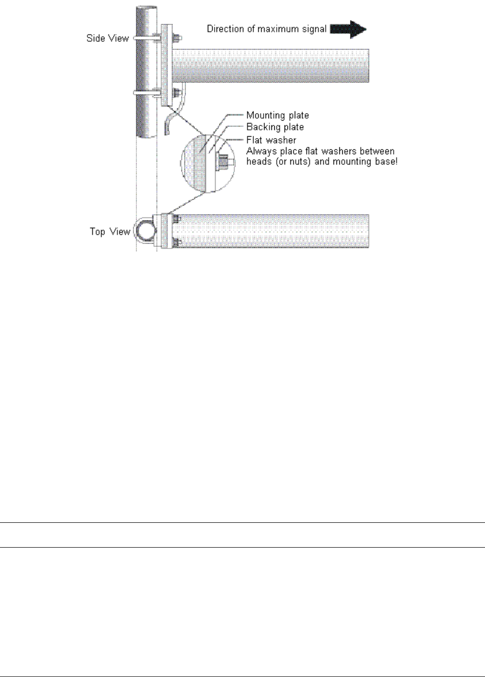
Tsunami MP.11 Antenna Installation Guide
Figure 8. Mounting 14 dBi Antenna to a Mast
Mounting on a Flat Surface
For mounting the antenna to a flat vertical surface, you must provide a smooth surface for the antenna mount.
On wall surfaces such as brick, block or stucco, use an intermediate surface such as a plywood board or metal
plate between the wall and antenna. The intermediate surface must be of sufficient strength to prevent distortion
of the antenna base when the mounting hardware is tightened.
To mount the antenna proceed as follows:
1. Verify whether you have all the following items:
The 2.4 GHz antenna
(optional) an intermediate plate
4 plugs and screws
4 flat washers
An electric drill
A screwdriver to tighten the screws
2. Note the arrows on the mounting plate; mount the antenna with the arrows pointing up.
3. Attach the antenna using the intermediate plate, metal backing plate and flat washers.
CAUTION! Always use flat washers between the screws and the plastic mounting plate. Avoid over-
tightening nuts and screws to prevent damage to the mounting plate.
Chapter 4. Recommended Antennas 43

Tsunami MP.11 Antenna Installation Guide
Technical Specifications
Mechanical
Size 44.7 cm (18 in)
Mounting method Vertical or horizontal mast with an outside diameter between 28 mm (1.102 in)
and 41 mm (1.625 in) using U-bolts.
Wall using plugs and screws
Connector1 Standard N (female)
Cable
Type RG58A/U, 50 ohms low-loss coaxial
Color White
Electrical
Frequency Range 2.4 GHz
VSWR Less than 2:1, 1.5:1 nominal
Nominal Impedance 50 ohms
Gain 14 dBi
Front-to-back ratio Greater than 20 dB
Half-Power Beamwidth
Elevation Plane (vertical) 30.8 degrees
Azimuth Plane (horizontal) 31.4 degrees
Polarization Linear vertical (standard mounting)
Horizontal (when mounted differently; see “Mounting the Directional Antenna” on
page 42).
Antenna Environment
Operating temperature -40 degrees C (-40 degrees F) to +60 degrees C (+140 degrees F)
Wind/survival At least 200 km/h (124 mph)2
1See also “Selecting the Correct Connector Type” on page 37.
2At least 100 km/h (62 mph) with 1.25 cm (0.5 in) ice.
Table 11. Specifications 14 dBi Directional Antenna
Chapter 4. Recommended Antennas 44
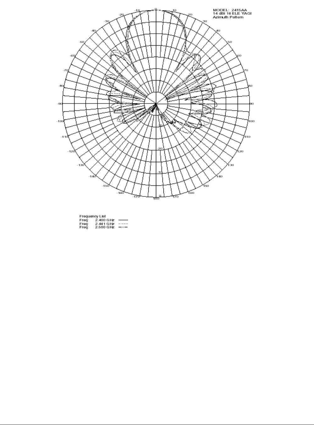
Tsunami MP.11 Antenna Installation Guide
Pattern
Figure 9. Azimuth Plane (Horizontal), 14 dBi Directional Antenna
Chapter 4. Recommended Antennas 45
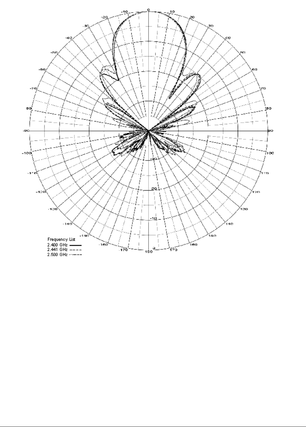
Tsunami MP.11 Antenna Installation Guide
Figure 10. Elevation Plane (Vertical), 14 dBi Directional Antenna
Chapter 4. Recommended Antennas 46

Tsunami MP.11 Antenna Installation Guide
7 DBI OMNI-DIRECTIONAL BASE UNIT ANTENNA
General Description
The Tsunami 7 dBi Omni-Directional Base Unit Antenna is a broadband antenna for the 2.4 GHz frequency band
featuring an omni-directional pattern with a nominal gain of 7 dBi.
The pole-type antenna is enclosed in a weatherproof protective covering (“radome”). This vertically polarized
antenna can be mounted to an antenna mast with an outside diameter of up to 65 mm (2.5 in).
For detailed specifications see the table in this appendix.
DANGER! When selecting an antenna location, ensure that the general precautions are met to avoid
possible contact with electrical power lines. See the National Electrical Code for proper
grounding of the antenna mast
Mounting the Omni-directional Antenna
You can mount the 7 dBi antenna to a mast only. This antenna uses vertical polarization, which is the most
common type of polarization for omni-directional antennas.
Mounting to a Mast
To mount the antenna to a mast proceed as follows:
1. Verify that you have all the items listed below:
º The 7 dBi Pole Antenna
º The O-shaped metal bracket
º The U-bolt, nuts and lock washers
º A small wrench to tighten the nuts
2. Position the bracket (item d in the following figure) to the top of the antenna mast (item b).
3. Place the U-bolt (item c) around the antenna mast, and slide its ends through the corresponding holes of the
bracket.
4. Use the lock-washers (item e) and nuts (item f) to secure the bracket to the mast. Use a wrench to tighten
the nuts.
5. Next, feed the antenna cable of the 7 dBi Omni-Directional Base Unit Antenna (item a) through the hole of
the mounting bracket.
6. As shown in the following figure, slide the antenna down until its metal base is enclosed by the mounting
bracket.
Chapter 4. Recommended Antennas 47
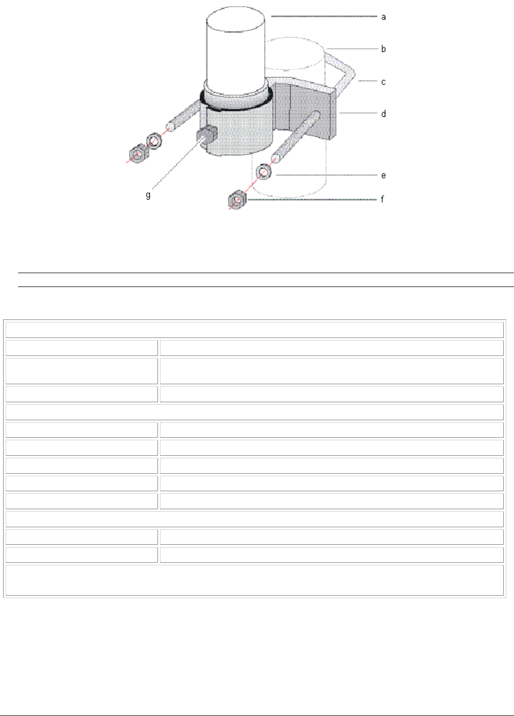
Tsunami MP.11 Antenna Installation Guide
Figure 11. Mounting the 7 dBi Antenna to a Mast
7. Use a wrench to tighten the bracket bolt (item g) to fix the antenna into its position.
CAUTION! Avoid over-tightening the hose-clip nut to avoid damage to the clip and your antenna.
Technical Specifications
Mechanical
Size 43.2 cm (17 in)
Mounting method Clamps to vertical mast with outside diameter between 35 mm (1.4 in) and 65
mm (2.55 in)
Connector1 Standard N (female)
Electrical
Frequency Range 2.4 GHz
VSWR Less than 2:1 nominal
Nominal Impedance 50 ohms
Gain y dBi
Polarization Linear vertical
Antenna Environment
Operating temperature -40 degrees C (-40 degrees F) to +60 degrees C (+140 degrees F)
Wind/survival At least 200 km/h (124 mph)2
1See also “Selecting the Correct Connector Type” on page 37.
2At least 100 km/h (62 mph) with 1.25 cm (0.5 in) ice.
Table 12. Specifications 7 dBi Omni-Directional Base Unit Antenna
Chapter 4. Recommended Antennas 48
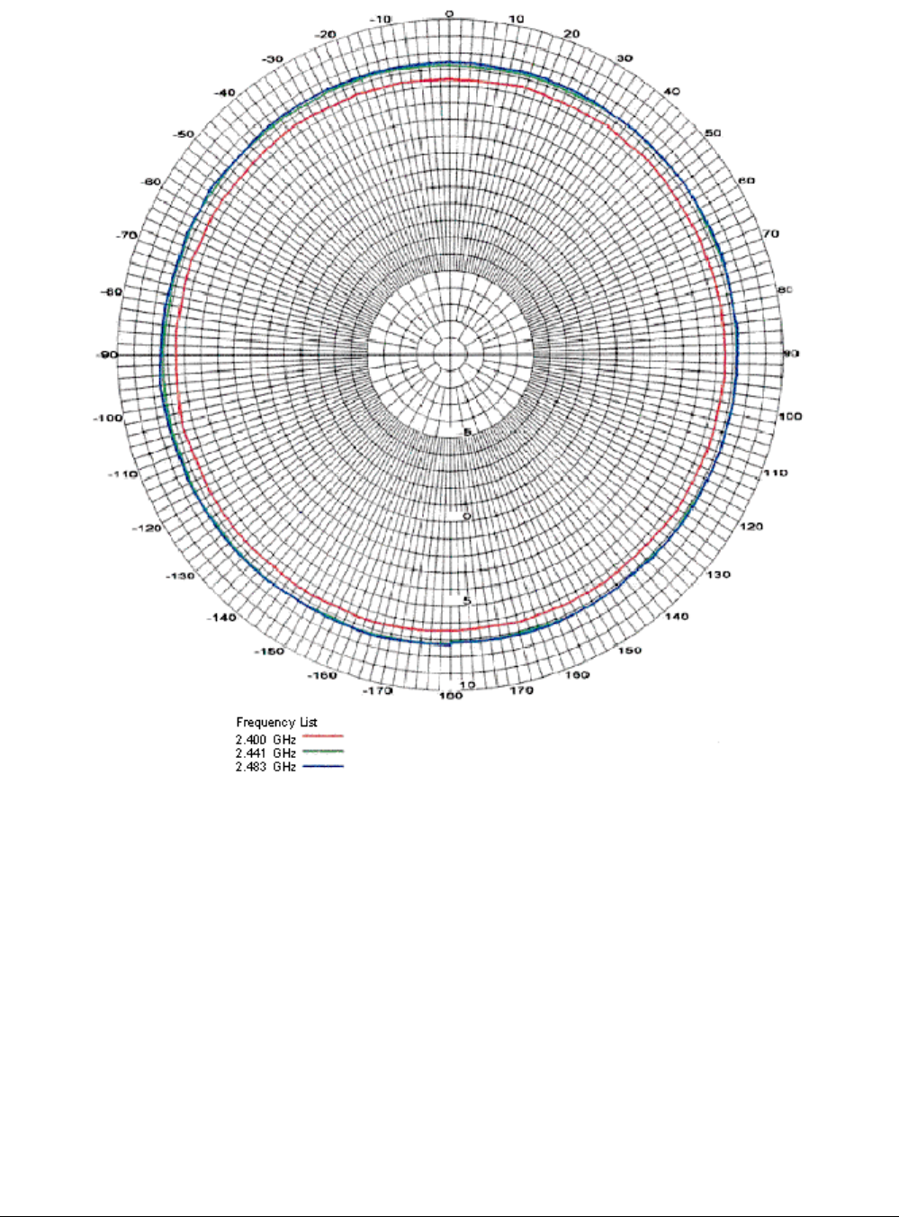
Tsunami MP.11 Antenna Installation Guide
Pattern
Figure 12. Azimuth Plane (Horizontal), 7 dBi Omni-Directional Base Unit Antenna
Chapter 4. Recommended Antennas 49
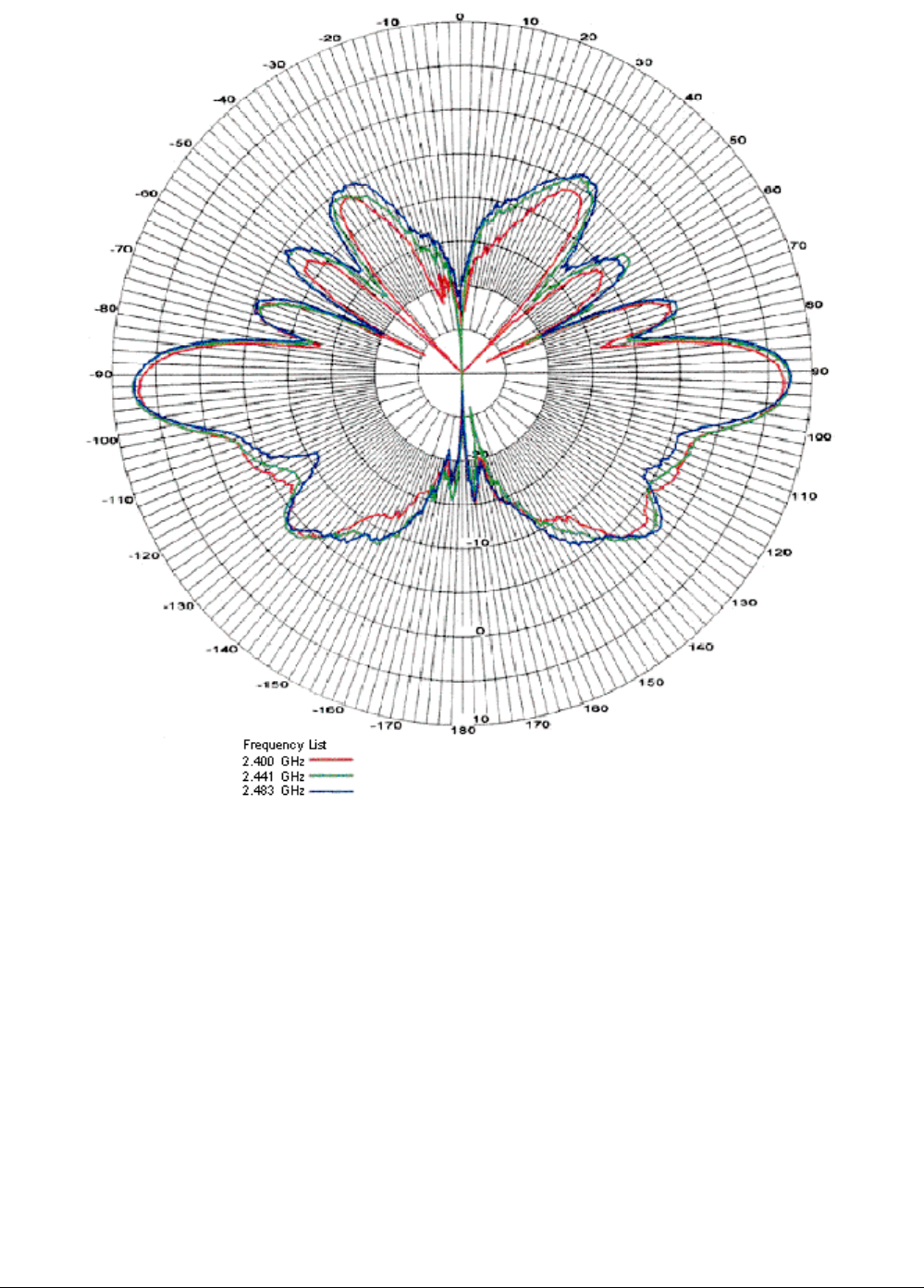
Tsunami MP.11 Antenna Installation Guide
Figure 13. Elevation Plane (Vertical), 7 dBi Omni-Directional Base Unit Antenna
Chapter 4. Recommended Antennas 50
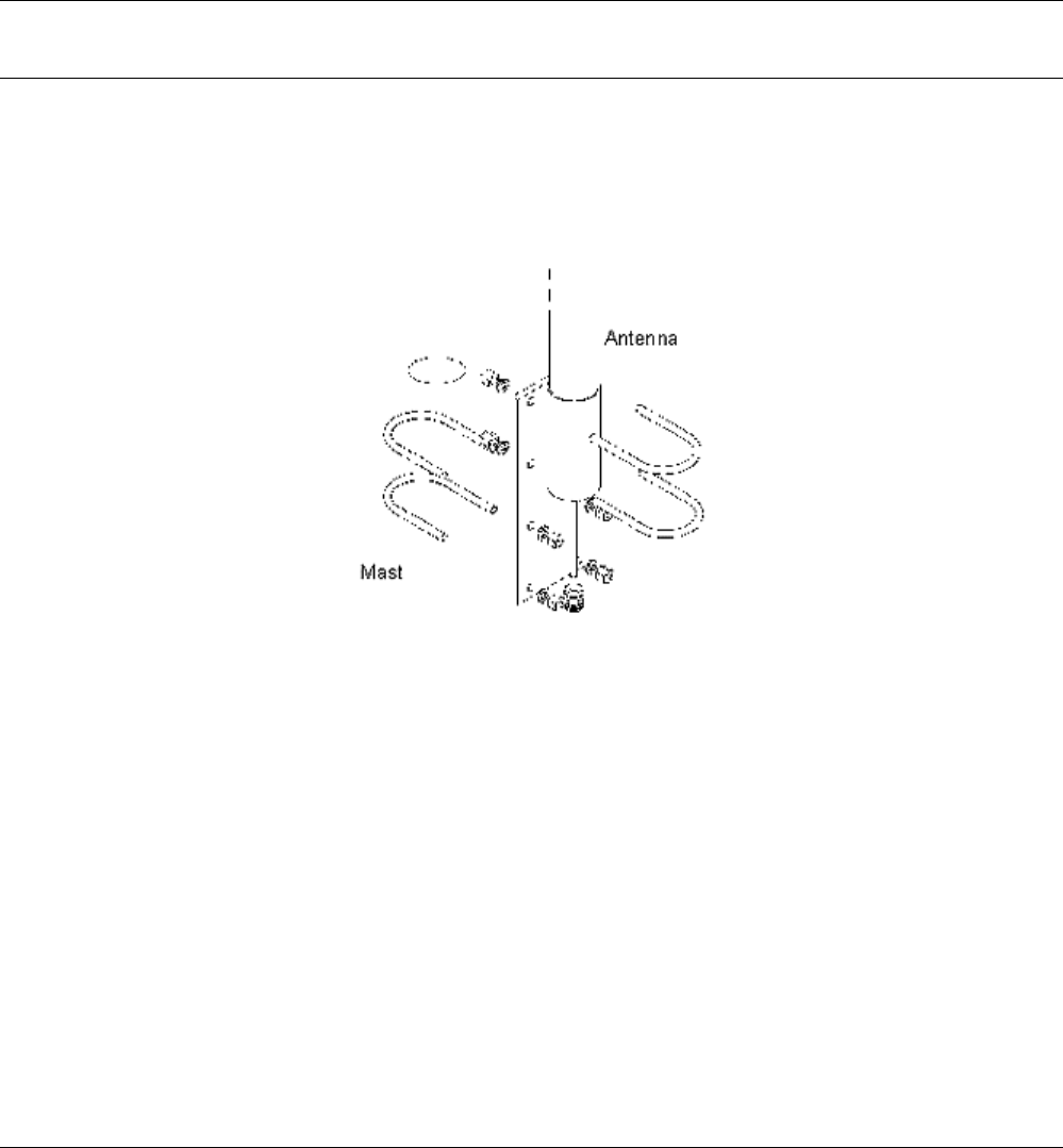
Tsunami MP.11 Antenna Installation Guide
10 DBI OMNI-DIRECTIONAL BASE UNIT ANTENNA
General Description
The Tsunami 10 dBi Omni-Directional Base Unit Antenna is a broadband antenna for the 2.4 GHz frequency
band featuring an omni-directional pattern with a nominal gain of 10 dBi.
This antenna is typically used in combination with a Base Unit.
The pole-type antenna is enclosed in a weatherproof protective covering (“radome”). This vertically polarized
antenna can be mounted to an antenna mast with an outside diameter of up to 51 mm (2.0 in).
For detailed specifications see the table in this appendix.
DANGER! When selecting an antenna location, ensure that the general precautions are met to avoid
possible contact with electrical power lines. See the National Electrical Code for proper
grounding of the antenna mast
Mounting Instructions
1. Attach the ferrule of the antenna to the mounting bracket with two U-bolts as shown in the following figure.
2. Next use the remaining two U-bolts to attach the mounting bracket to the mast. Tighten nuts to 9 Nm (7 ft-
lbs).
Figure 14. Mounting the 10 dBi Antenna
Chapter 4. Recommended Antennas 51

Tsunami MP.11 Antenna Installation Guide
Technical Specifications
Mechanical
Size 91.4 cm (36 in)
Mounting Method Clamps to vertical mast with outside diameter between 35 mm (1.4 in) and 51
mm (2.0 in)
Connector1 Standard N (female)
Cable
Type RG-303, 50 ohms low-loss coaxial
Length 25 cm (10 in)
Color Tan
Electrical
Frequency Range 2.4 GHz
VSWR Less than 2:1 nominal
Nominal Impedance 50 ohms
Gain 20 dBi
Polarization Linear vertical
Antenna Environment
Operating Temperature -40 degrees C (-40 degrees F) to +60 degrees C (+140 degrees F)
Wind/survival (mph) At least 240 km/h (150 mph)2
1See also “Selecting the Correct Connector Type” on page 37.
2At least 200 km/h (124 mph) with 1.25 cm (0.5 in) ice.
Table 13. Specifications 10 dBi Omni-Directional Base Unit Antenna
Chapter 4. Recommended Antennas 52
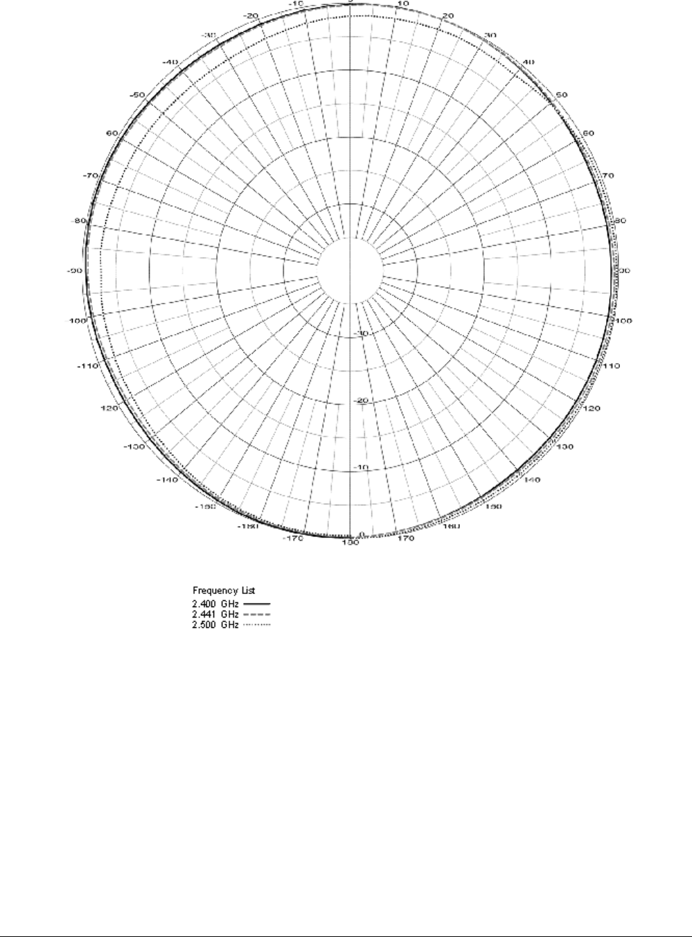
Tsunami MP.11 Antenna Installation Guide
Pattern
Figure 15. Azimuth Plane (Horizontal), 10 dBi Omni-Directional Base Unit Antenna
Chapter 4. Recommended Antennas 53
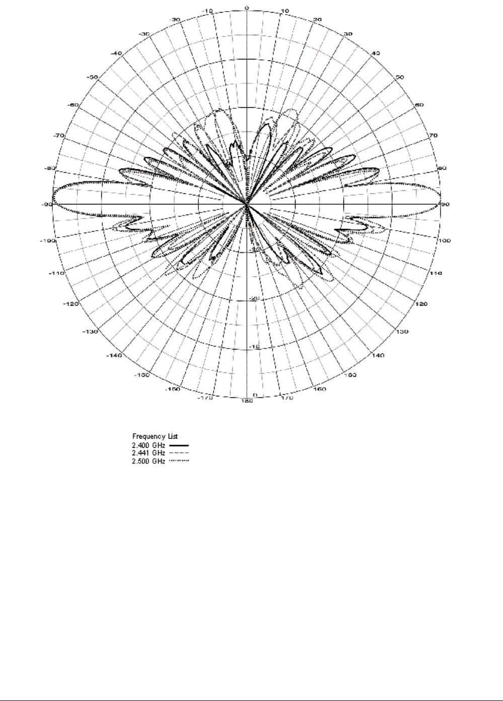
Tsunami MP.11 Antenna Installation Guide
Figure 16. Elevation Plane (Vertical), 10 dBi Omni-Directional Base Unit Antenna
Chapter 4. Recommended Antennas 54
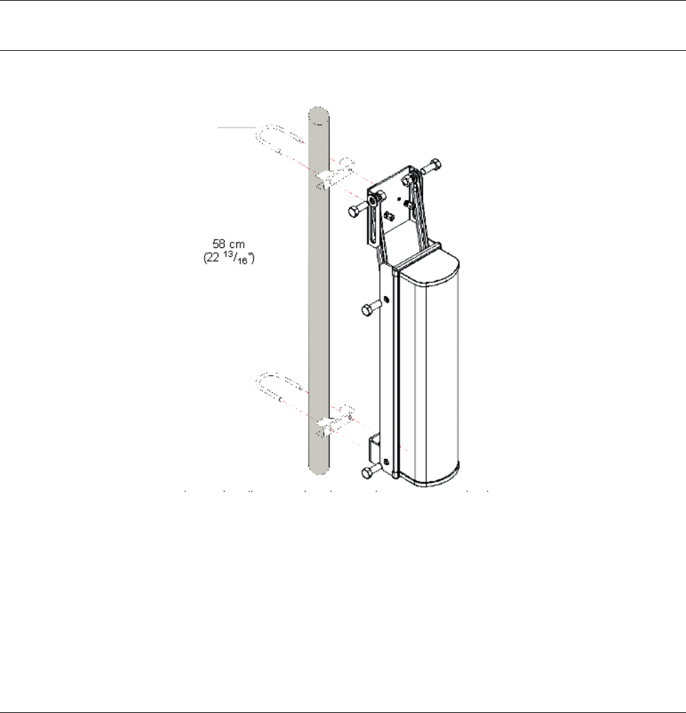
Tsunami MP.11 Antenna Installation Guide
12 DBI DIRECTIONAL WIDE ANGLE ANTENNA
General Description
The Tsunami 12 dBi Directional Wide Angle Antenna is for the 2.4 GHz frequency band is a perfect match
between the features of the:
▪ Directional antennas
▪ Omni-directional antennas
Typically used in combination with a Base Unit, this antenna can be mounted to an antenna mast with an
outside diameter of up to 51 mm (2.0 in).
Mounting Instructions
DANGER! When selecting an antenna location, ensure that the general precautions are met to avoid
possible contact with electrical power lines. See the National Electrical Code for proper
grounding of the antenna mast.
1. Attach the U-bolts, tube mounting bracket, upper mounting bracket, and lower mounting bracket to the mast
and spaced as shown in the following figure.
Figure 17. Mounting the 12 dBi Wide Angle Antenna
2. Assemble the angle adjustment brackets to the upper mounting bracket with 1/2 inch bolts, lock washers,
flat washers and nuts.
3. Next assemble the angle adjustment brackets and lower mounting brackets to the antenna base plate with
1/2 inch bolts, lock washers, and nuts.
º This adjustment is for 0 degree mounting. To adjust from 0 to -20 degrees, loosen the hardware at both
ends of the angle adjustment bracket and slide it in the slot to the preferred angle.
4. Tighten hardware securely. The U-bolts should be tightened to 9 Nm (7 ft-lbs).
Chapter 4. Recommended Antennas 55

Tsunami MP.11 Antenna Installation Guide
Technical Specifications
Mechanical
Size (LxWxD) 181 x 53.7 x 76 cm (21.1 x 7.1 x 3.0 in)
Mounting Method Clamps to vertical mast with outside diameter between 35 mm (1.4 in) and 51
mm (2.0 in)
Connector1 Standard N (female)
Electrical
Frequency Range 2.4 GHz
VSWR Less than 2:1 nominal
Nominal Impedance 50 ohms
Gain 12 dBi
Polarization Linear vertical
Half-Power Beamwidth (at vertical polarization)
Elevation Plane (vertical) 13 degrees
Azimuth Plane (horizontal) 125 degrees
Antenna Environment
Operating Temperature -40 degrees C (-40 degrees F) to +60 degrees C (+140 degrees F)
Wind/survival (mph) At least 200 km/h (124 mph)2
1See also “Selecting the Correct Connector Type” on page 37.
2At least 100 km/h (62 mph) with 1.25 cm (0.5 in) ice.
Table 14. Specifications 12 dBi Directional Wide Angle Antenna
Chapter 4. Recommended Antennas 56
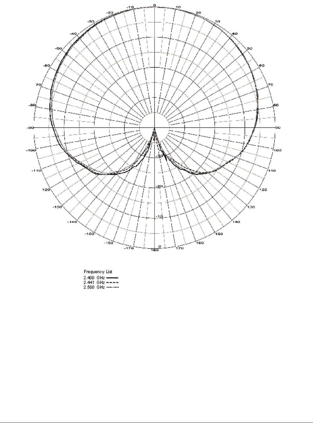
Tsunami MP.11 Antenna Installation Guide
Pattern
Figure 18. Azimuth Plane (Horizontal), 12 dBi Directional Wide Angle Antenna
Chapter 4. Recommended Antennas 57
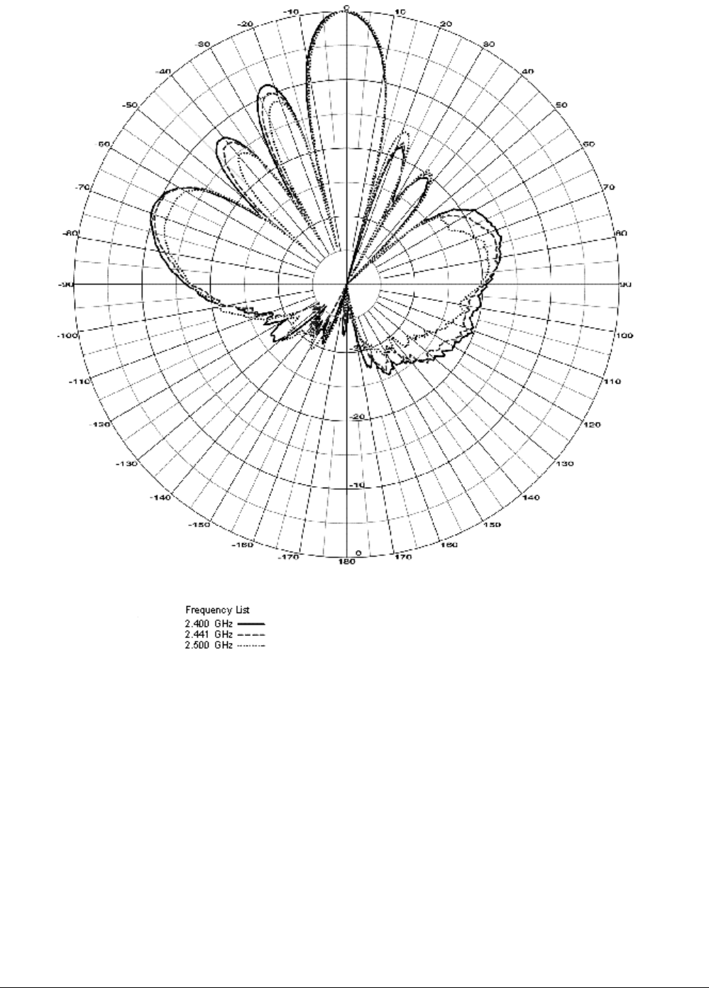
Tsunami MP.11 Antenna Installation Guide
Figure 19. Elevation Plane (Vertical), 12 dBi Directional Wide Angle Antenna
Chapter 4. Recommended Antennas 58

Tsunami MP.11 Antenna Installation Guide
24 DBI DIRECTIONAL PARABOLIC GRID ANTENNA
General Description
The Tsunami 24 dBi Directional Parabolic Grid Antenna is a broadband antenna for the 2.4 GHz frequency band.
The grid-type antenna allows either horizontal or vertical mounting on an antenna mast with an outside diameter
of up to 51 mm (2 in).
This antenna typically is used in combination with a Subscriber Unit.
Note: The 24 dBi Directional Parabolic Grid Antenna is not allowed in countries that adhere to the ETSI radio
regulations (also France).
In countries that adhere to the FCC regulations, use of this antenna is allowed only when operated with
specific radio channels that can be set on the Tsunami MP.11.
Kit Contents
The 24 dBi Directional Parabolic Grid Antenna comes in two boxes with the following contents
Feed Box:
1 Feed assembly
1 Sub-reflector
1 #6 x 1/2 inch stainless screw
2 Stainless 1/4 x 20 hex nuts
2 Stainless lock washers
2 Stainless carriage bolts
Reflector Box:
2 Reflector halves
2 Stainless U-bolts
2 Mast clamps
1 Mounting ‘L’ shaped bracket
4 Keps nuts (4) #8-32 machine screws
6 Stainless 1/4 x 20 hex nuts
6 Stainless lock washers
2 Stainless carriage bolts
1 Stainless flat plate washer
Note: Prior to installation, or climbing the roof, verify if all parts and components are included. If any part is
missing or appears to be damaged, consult your authorized Proxim Tsunami reseller.
Chapter 4. Recommended Antennas 59
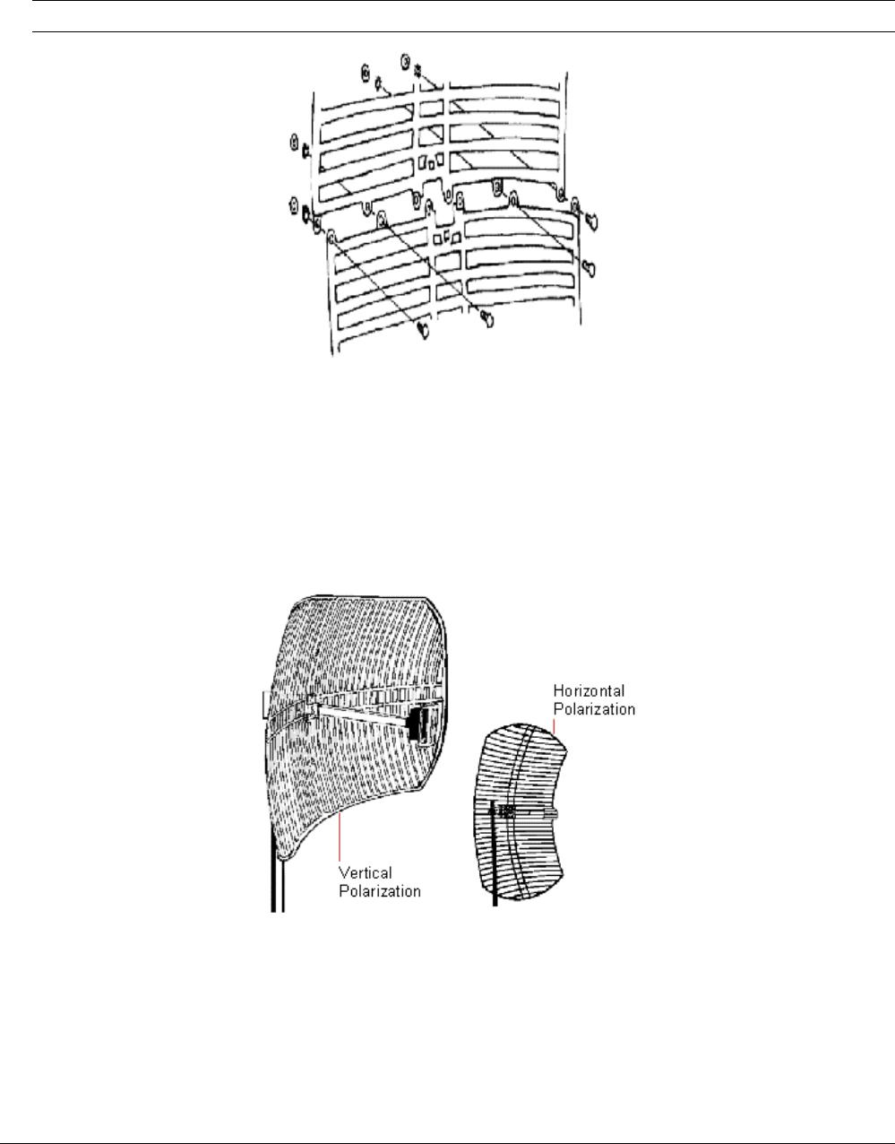
Tsunami MP.11 Antenna Installation Guide
Assembling the Antenna
1. Assemble the two reflector halves inserting the four #8-32 machine screws through the front. Secure with
the keps nuts on the back.
Note: Loosely tighten all hardware until completely assembled and then tighten securely.
Figure 20. Assemble the Reflector
2. Place the sub-reflector on the front of the feed and secure with the #6 x 1/2 inch stainless screw.
3. Determine the polarity of the antenna (see the following figure).
º Horizontal polarity, (the reflector ribs and the sub reflector at the front end of the antenna are aligned
horizontally).
º Vertical polarity: (the reflector ribs and the sub reflector at the front end of the antenna are aligned
vertically).
Figure 21. Determine Polarization
Polarity of the antenna must always be the same as the polarity of the antenna on the opposite side of the
link!
4. Place the ‘L’ bracket on the back of the antenna.
5. Insert two carriage bolts from the front to attach.
Chapter 4. Recommended Antennas 60
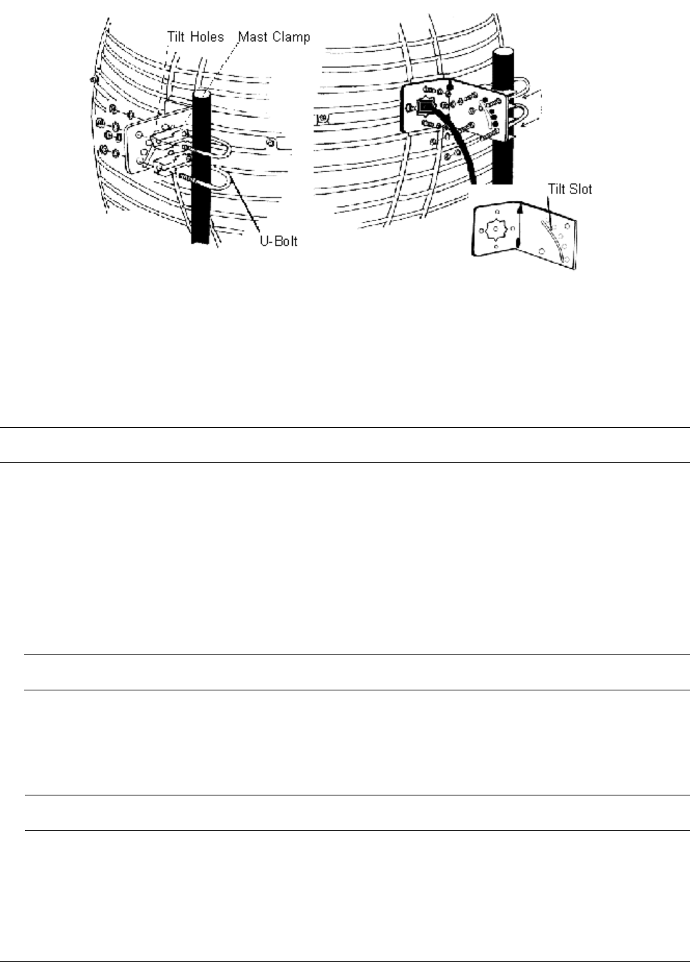
Tsunami MP.11 Antenna Installation Guide
Figure 22. Attach Mounting Bracket
6. Secure on the back with the lock washers and nuts.
7. Recheck the dipole feed assembly for the proper polarity.
8. Attach the feed on the front with 2 carriage bolts. Secure on the back with the lock washers and nuts.
Mounting the Antenna
DANGER! Installation of antenna near power lines is dangerous! Before you proceed, make sure you
have read and understood the safety precautions.
1. Before climbing the roof, make sure you have:
º The assembled antenna.
º The U-bolts and mast clamps to mount the grid antenna to the mast.
2. Determine the desired alignment of the antenna:
º For horizontal alignment you need both U-bolts and the 4 lock washers and nuts.
º For tilted alignment, you use only a single U-bolt and two lock washers and nuts. This mounting method
lets you mount the antenna with an elevation in 10 degrees increments.
CAUTION! Tilted alignment is not suitable for environments where the antenna is subject to high
wind conditions.
3. Place the U-bolt(s) around the mast as depicted in the previous figure.
4. Slide the mast clamps over the U-bolts.
5. Slide the ‘L’ bracket over the U-bolts and fasten the grid antenna to the U-bolts using the lock washers and
nuts.
Note: For tilted elevation mounting, use the flat plate washer on the adjustable tilt slot to mount and
secure the antenna to the desired elevation angle.
Chapter 4. Recommended Antennas 61
Tsunami MP.11 Antenna Installation Guide
Technical Specifications
Mechanical
Size (HxWxD) 61.0x91.4x38.1 cm (24x36x15 in)
Mounting method Clamps to vertical mast with outside diameter between 26 mm (1.102 in) and
51 mm (2.0 in)
Cable Type RG-8A/U, 50 ohms low-loss coax
Cable Length 60 cm (24 in)
Cable Color Black
Connector1 Standard N (female)
Electrical
Frequency Range 2.4 GHz
VSWR Less than 2:1 nominal
Nominal Impedance 50 ohms
Gain 24 dBi
Polarization Linear vertical for standard mounting
Horizontal when mounted differently (see “Mounting the Antenna” on page 61)
Half-Power Beamwidth (at vertical polarization)
Elevation Plane (vertical) 10 degrees
Azimuth Plane (horizontal) 6.5 degrees
Antenna Environment
Operating Temperature -40 degrees C (-40 degrees F) to +60 degrees C (+140 degrees F)
Wind/survival (mph) At least 200 km/h (124 mph)2
1See also “Selecting the Correct Connector Type” on page 37.
2At least 100 km/h (62 mph) with 1.25 cm (0.5 in) ice.
Table 15. Specifications 24 dBi Directional Parabolic Grid Antenna
Chapter 4. Recommended Antennas 62
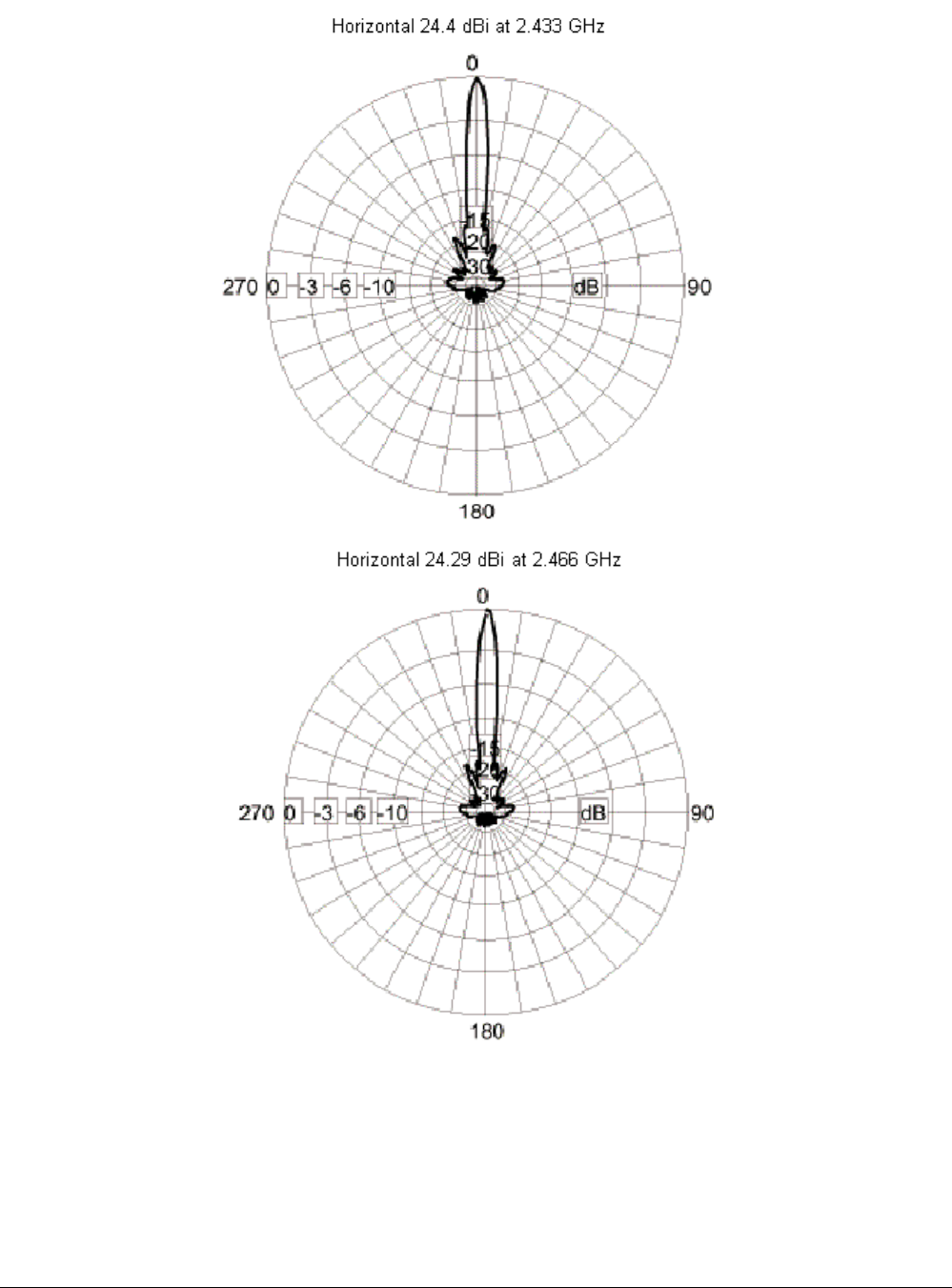
Tsunami MP.11 Antenna Installation Guide
Horizontal Pattern
Figure 23. Azimuth Plane (Horizontal), 24 dBi Directional Parabolic Grid Antenna
Chapter 4. Recommended Antennas 63
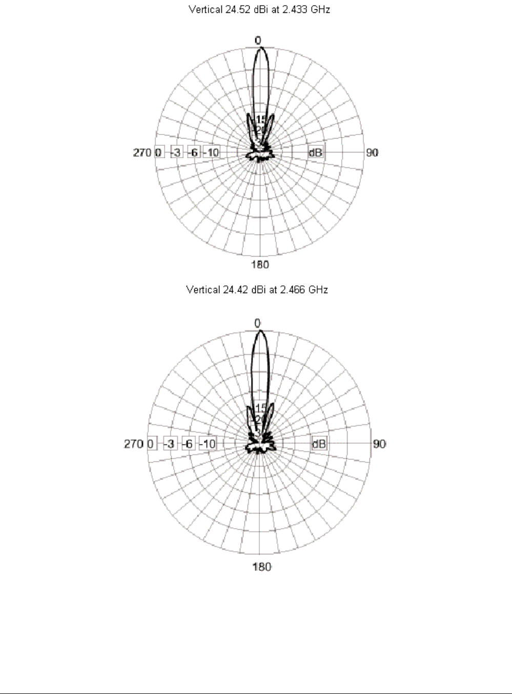
Tsunami MP.11 Antenna Installation Guide
Vertical Pattern
Figure 24. Elevation Plane (Vertical), 24 dBi Directional Parabolic Grid Antenna
Chapter 4. Recommended Antennas 64
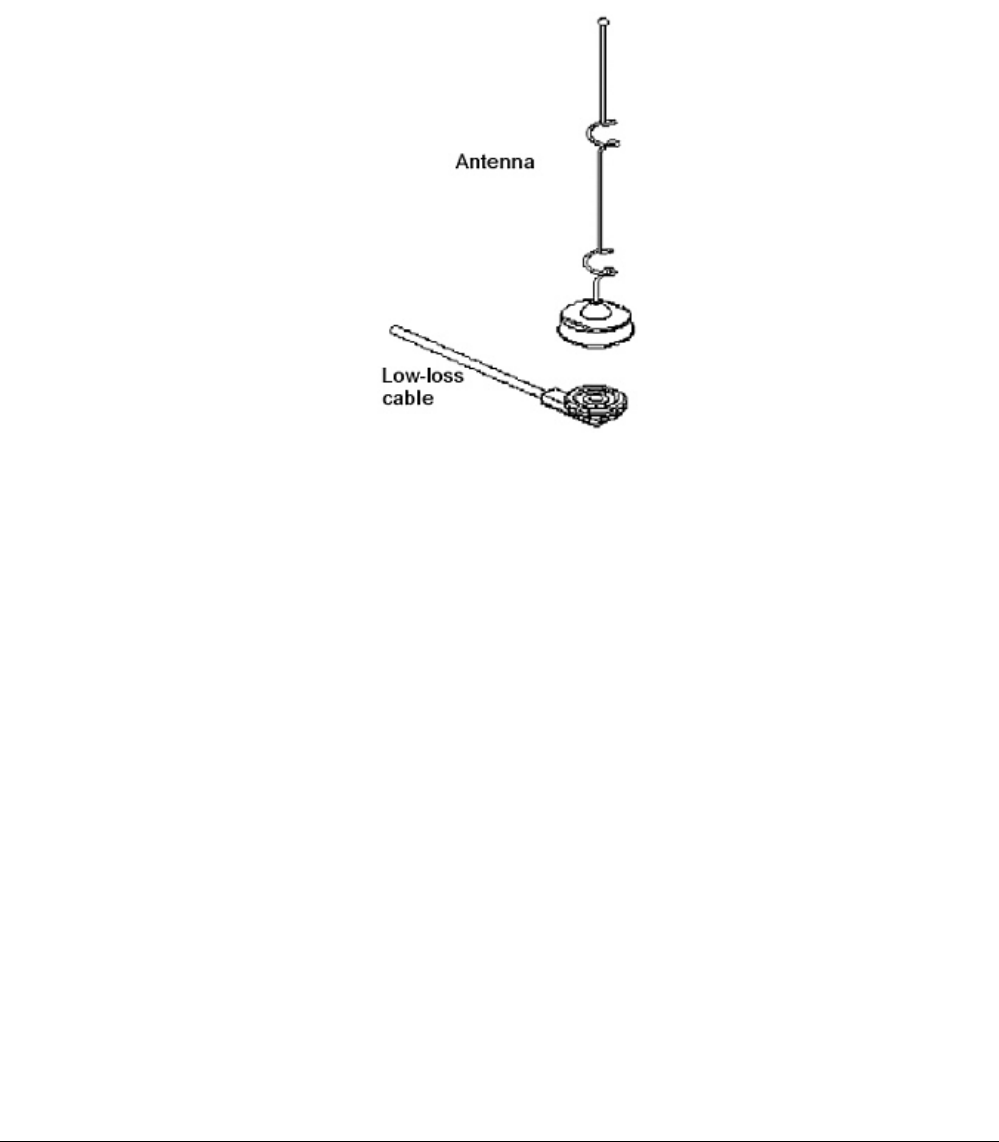
Tsunami MP.11 Antenna Installation Guide
5 DBI OMNI-DIRECTIONAL ANTENNA
General Description
The Tsunami 5 dBi Omni-Directional Antenna is designed for use in rugged environments. The antenna operates
in the frequency range from 2400 to 1500 MHz. It is supplied with a special proprietary FCC plug and a low-loss
cable.
This antenna uses vertical polarization, which is the most common type of polarization for omni-directional
antennas.
Figure 25. 5 dBi Omni-Directional Antenna
Chapter 4. Recommended Antennas 65
Tsunami MP.11 Antenna Installation Guide
Technical Specifications
Mechanical
Size 24 cm (9.5 in)
Mounting Method Through a 19 mm (0.75 in) M-type hole using a mounting plate.
Connector Standard N female1 snap-on with 100% captive pin
Cable
Type 50 ohms low-loss cable
Length 2.5 m (8 ft.)
Color White
Electrical
Frequency Range 2.4 GHz
VSWR Less than 2:1 nominal
Nominal Impedance 50 ohms
Gain 5 dBi
Polarization Linear vertical
Antenna Environment
Operating Temperature -40 degrees C (-40 degrees F) to +60 degrees C (+140 degrees F)
Wind/survival At least 200 km/h (124 mph)2
1See also “Selecting the Correct Connector Type” on page 37.
2At least 100 km/h (62 mph) with 1.25 cm (0.5 in) ice.
Table 16. Specifications 5 dBi Omni-Directional Antenna
Chapter 4. Recommended Antennas 66
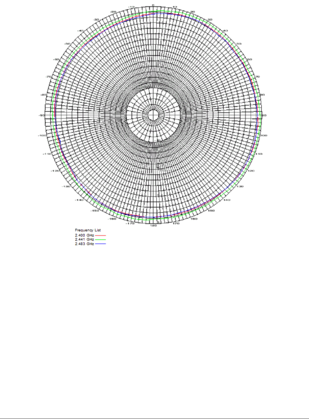
Tsunami MP.11 Antenna Installation Guide
Pattern
Figure 26. Azimuth Plane (Horizontal), 5 dBi Omni-Directional Antenna
Chapter 4. Recommended Antennas 67
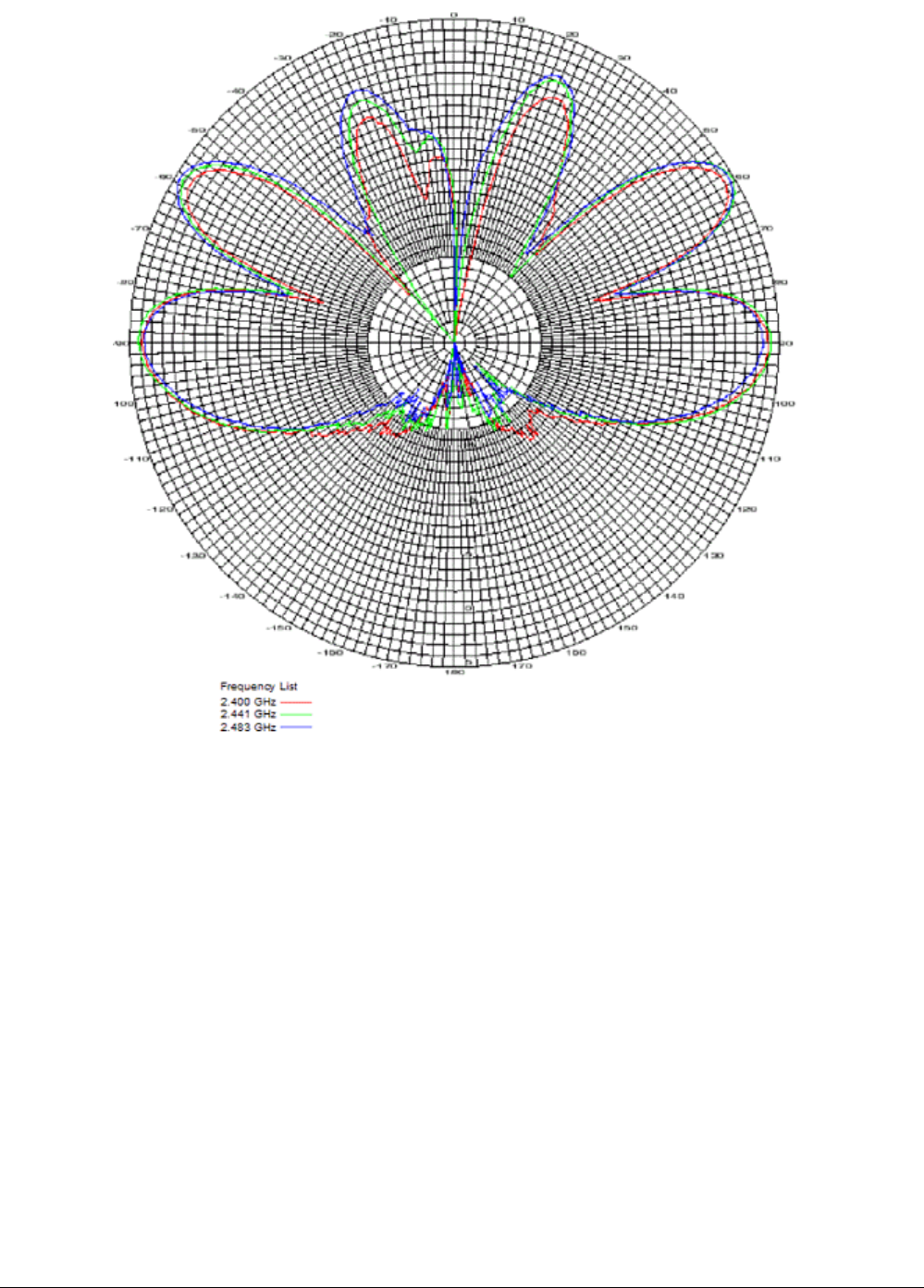
Tsunami MP.11 Antenna Installation Guide
Figure 27. Elevation Plane (Vertical), 5 dBi Omni-Directional Antenna
Chapter 4. Recommended Antennas 68
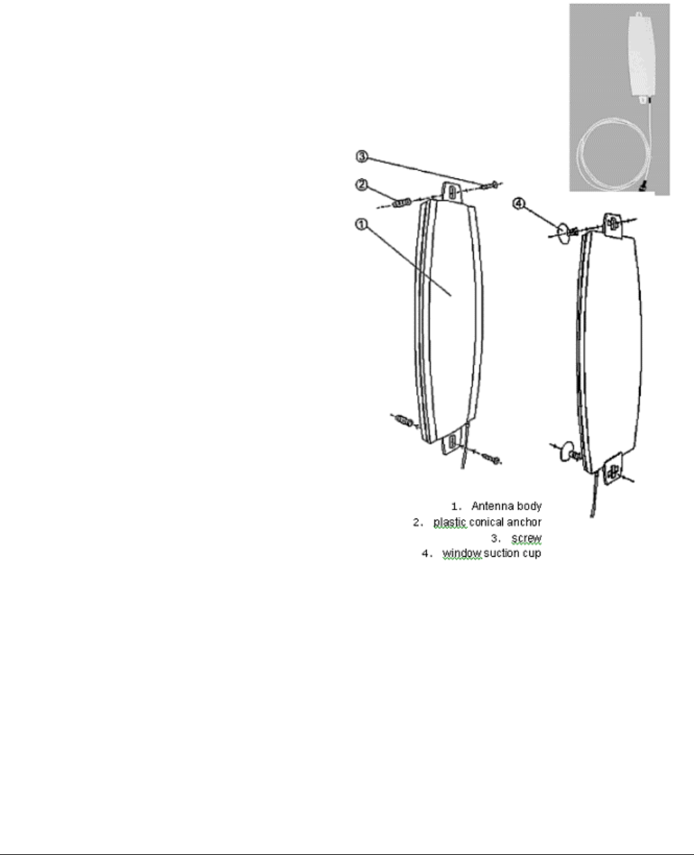
Tsunami MP.11 Antenna Installation Guide
HIGH GAIN PANEL DIRECTIONAL ANTENNA FOR 2.4 GHZ
General Description
The 12 dBi window antenna is a high-gain antenna for the 2.4 GHz frequency band. This antenna is typically
used in combination with a Subscriber Unit.
Mounting Instructions
Package contents:
▪ ANT24-1200 Antenna
▪ Extension Cable (3m)
▪ Mounting Kit
▪ Quick Installation Guide
Wall Mount for Outdoor/Indoor Application
A. Insert the plastic wall plug (2) into the wall
B. Insert the screw (3) into the plastic wall plug
through the antenna mounting hole and tighten
Window Suction Mount for Indoor Application
1.
A
ntenna bod
y
2. plastic conical ancho
r
3. screw
4. window suction cup
A. Insert the window suction cup through the
antenna mounting hole.
B. Turn the suction cup one quarter to
lock it into position.
C. Press the window suction cup onto
the window glass.
Chapter 4. Recommended Antennas 69
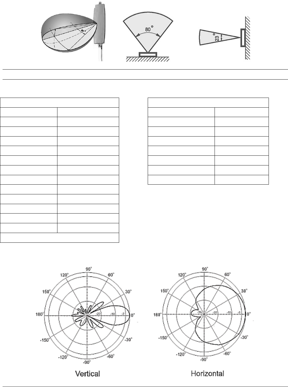
Tsunami MP.11 Antenna Installation Guide
Coverage
Note: The bulged side of the antenna must point to the Base Station.
Hardware Specifications
Electrical Specification Environmental & Mechanical Characteristics
Frequency range 2400 MHz – 2700 MHz Survival wind speed 180 km/hr
Gain 12 dBi Temperature -40º C to +80º C
VSWR 2.0 : 1 Max. Humidity 95% @ 25º C
Polarization Linear, vertical Lightning Protection DC ground
HPBW / horizontal 84 degrees Radome color white
HPBW / vertical 23 degrees Radome material ABS, UV resistant
Front to back ratio 18 dB Weight 0.6 kgw
Downtilt 0 degrees Dimensions 330 x 93 x 21 mm
Power handling 20 W (cw)
Impedance 50 Ohms
Connector N-Jack
Cable ULA-168; 200 cm
Cable loss 1.3 dB
*Exclusive of cable loss
Pattern
Chapter 4. Recommended Antennas 70
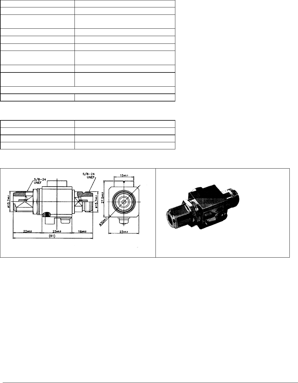
Tsunami MP.11 Antenna Installation Guide
SURGE PROTECTOR
Electrical Specifications
Part number 5054-SURGE
Frequency range DC~ 5.875 GHz
VSWR 1.25 : 1 Max.@ DC~4 GHz
1.45 : 1 Max.@ 4~5.875 GHz
Insertion loss 0.5 dB Min.@ DC~5.875 GHz
Impedance 50 Ω
DC breakdown voltage 90 V +/- 15%
Impulse breakdown
voltage
1000 V
Insulation resistance 10000 MΩ
Maximum withstand
current
5 KA
Connector
Connector type N-Female to N-Female
Mechanical and Environmental Specifications
Size 61 x 27.5 x 23 mm
Weight 105 gw
Temperature range -40~ +90 C
Salt Spray MIL-STD-202 method 101D
Mechanical Layout
Chapter 4. Recommended Antennas 71
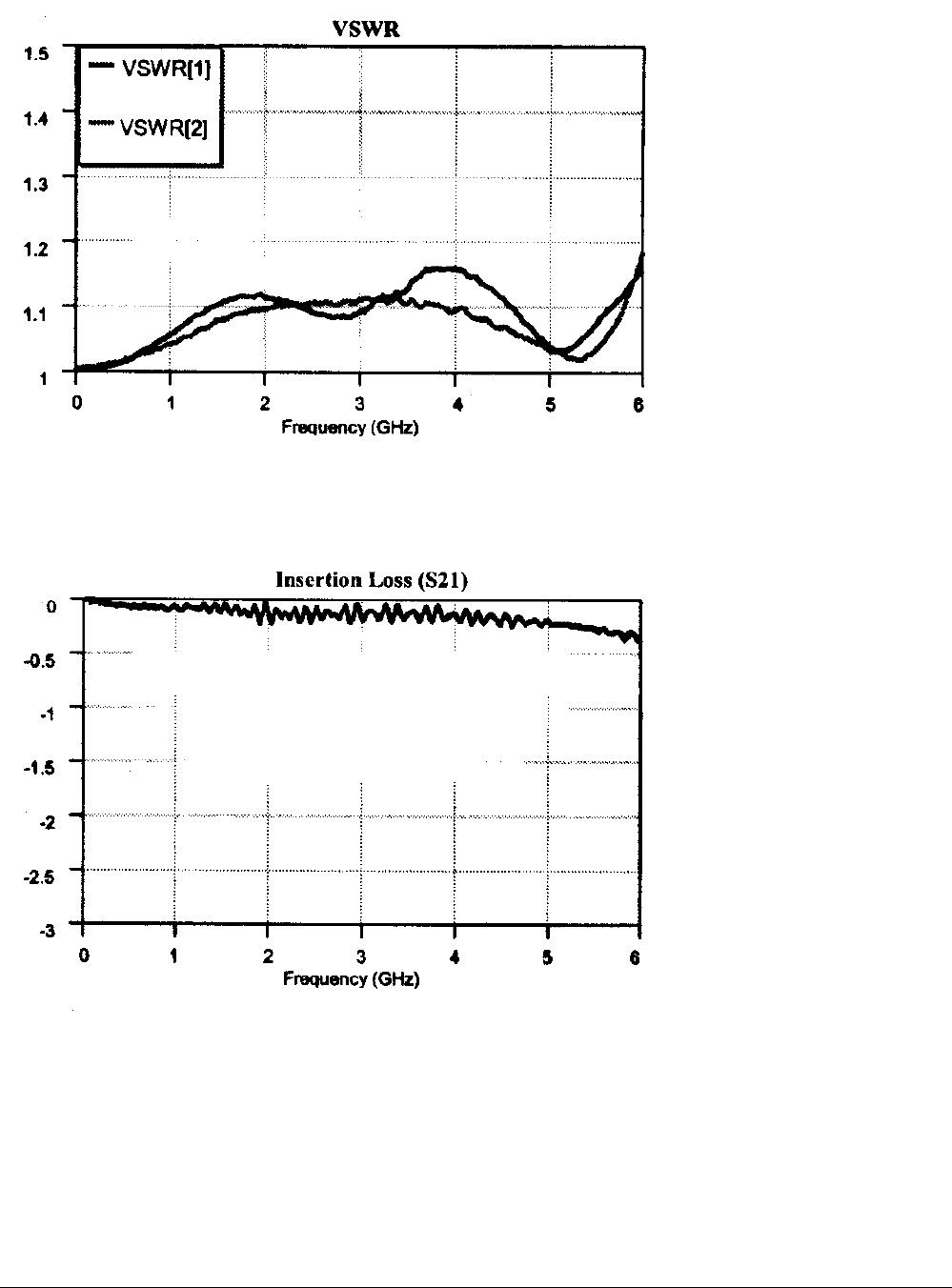
Tsunami MP.11 Antenna Installation Guide
VSWR and Insertion Loss
Chapter 4. Recommended Antennas 72
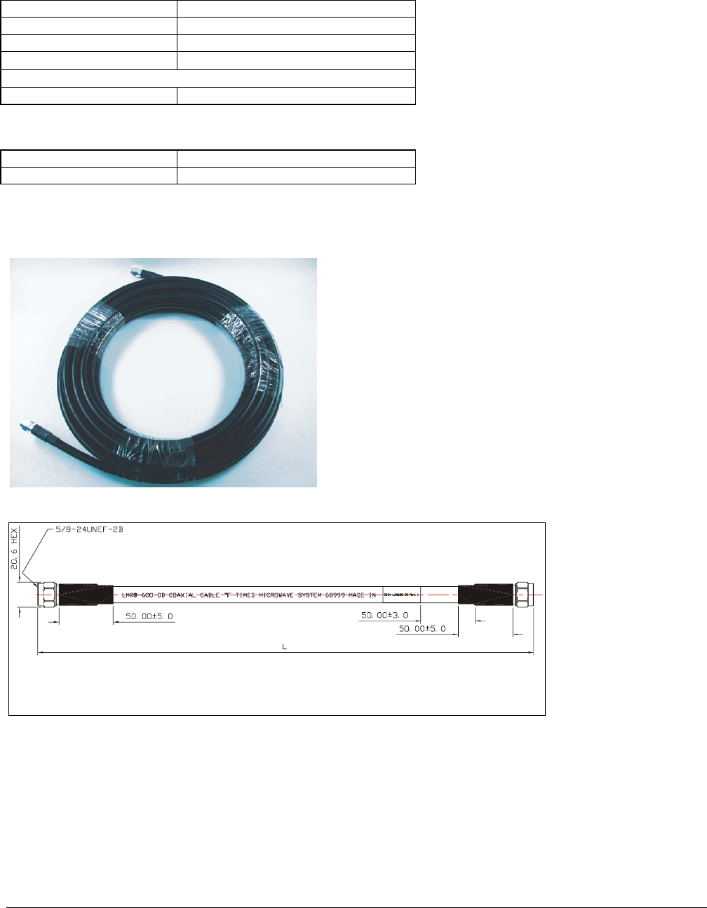
Tsunami MP.11 Antenna Installation Guide
LMR 600 CABLE – 50 FT
Electrical Specifications
Part number 5054-LMR600-50
Frequency range DC~ 5.875 GHz
Insertion loss 4.5 dB Max@ DC~5.875 GHz
Impedance 50 Ω
Connector
Connector type N-Male to N-Male
Mechanical and Environmental Specifications
Size of carton 115 x 375 x 375 mm
Cable length 50 ft
For more detailed specifications, see Times Microwave LMR-600 specification.
Mechanical Layout
Unit: mm
Chapter 4. Recommended Antennas 73
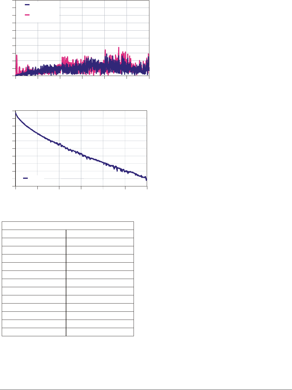
Tsunami MP.11 Antenna Installation Guide
VSWR and Insertion Loss
0
1
2
3
4
5 6
Frequency (GHz)
-5
-4.5
-4
-3.5
-3
-2.5
-2
-1.5
-1
-0.5
0
S21
0
1
2
3
4
5 6
Frequency (GHz)
VSWR
1
1.1
1.2
1.3
1.4
1.5
1.6
1.7
1.8
1.9
2
VSWR #1:1:
#1:
#2:
Insertion Loss (S21)
:
VSWR #2:
Attenuation
50 ft Times LMR-600 Typical Attenuation
Frequency (MHz) Attenuation (dB)
500 1.00
1000 1.49
1500 1.93
2000 2.29
2500 2.61
3000 2.92
3500 3.21
4000 3.45
4500 3.76
5000 4.04
5500 4.22
6000 4.61
Chapter 4. Recommended Antennas 74

Tsunami MP.11 Antenna Installation Guide
Support and Warranty
TECHNICAL SUPPORT
If you encounter problems when installing or using this product, consult the Proxim website:
http://support.Proxim.com/ for:
▪ The latest software, user documentation and product updates
▪ The Frequently Asked Questions (FAQ)
Alternatively, contact your local authorized Tsunami MP.11 reseller for Technical Support.
Help us to help you by completing the problem report form and include it with your e-mail or fax when contacting
Technical Support.
You can find the problem report form (report.txt) on the CD-ROM, and on the support pages of the Proxim
website.
Addresses of authorized Tsunami MP.11 resellers are listed in the “Contact & Ordering” section of the Proxim
website.
WARRANTY AND REPAIR
If it appears that your unit needs a repair or replacement, return the unit to your Dealer or Distributor in its
original packaging.
When returning a defective product for Warranty, always include the following documents:
▪ The Warranty Repair card (last page of this appendix)
▪ A copy of the invoice or proof of purchase
▪ Problem Report Form
Proxim Corporation extends a limited warranty from date of purchase of:
▪ Twelve (12) months for the Tsunami MP.11 hardware
▪ Twelve (12) months for the media on which the software is furnished and the reproduction of the software on
the media.
Upon proof-of-purchase Proxim Corporation shall, at its discretion, repair or replace the defective item at no cost
to the buyer.
Defective items shall be returned to the dealer or distributor:
▪ Freight prepaid.
▪ Accompanied by a copy of proof-of-purchase.
▪ Accompanied by a filled out Warranty and Repair card.
This warranty is contingent upon proper use in the application for which the products are intended and does not
cover products which have been modified without the seller’s approval or which have been subjected to unusual
physical or electrical demands or damaged in any way.
This Warranty constitutes the sole and exclusive remedy of any buyer or seller’s equipment and the sole and
exclusive liability of Proxim Corporation in connection with the products and is in lieu of all other warranties,
express, implied or statutory, including, but not limited to, any implied warranty of merchantability of fitness for a
particular use and all other obligations or liabilities of Proxim Corporation.
In no event is Proxim Corporation or any other party or person to be liable to you or anyone else for any
damages, including lost profits, lost savings or other incidental or consequential damages, or inability to use the
software provided on the software media even if Proxim Corporation or the other party person has been advised
of the possibility of such damages.
Support and Warranty 75

Tsunami MP.11 Antenna Installation Guide
TO BE FILLED OUT BY USER:
Product Description____________________________________________________________________
COMCODE (Product ID)________________________________________________________________
Serial Number________________________________________________________________________
Invoice Date (mm/dd/yyyy):______________________________________________________________
Name:______________________________________________________________________________
Title________________________________________________________________________________
Company ___________________________________________________________________________
Address ____________________________________________________________________________
City/State/Zip Code ___________________________________________________________________
Country ____________________________________________________________________________
Telephone __________________________________________________________________________
Fax ________________________________________________________________________________
TO BE FILLED OUT BY THE DEALER OR DISTRIBUTOR
Dealer Name ________________________________________________________________________
City/State/Zip Code ___________________________________________________________________
Country ____________________________________________________________________________
Telephone __________________________________________________________________________
Fax _______________________________________________________________________________
Warranty (Yes / No) __________________________________________________________________
Comment __________________________________________________________________________
Return Approval Reference ____________________________________________________________
Reported Problem Problem Description
Support and Warranty 76