Proxim Wireless MP11R-ABG MP.11x outdoor wireless Etherenet system User Manual MP 11 R FCC
Proxim Wireless Corporation MP.11x outdoor wireless Etherenet system MP 11 R FCC
Contents
manual 1

Tsunami MP.11-R Installation and Management Guide
Model 2454-R
Model 5054-R
Model 5054-R-LR
Model 4954-R
Model 954-R
Version 4.0.0

MP.11-R Installation and Management
2
Copyright
©2007 Proxim Wireless Corporation, San Jose, CA. All rights reserved. Covered by one or more of the following U.S. patents: 5,231,634;
5,875,179; 6,006,090; 5,809,060; 6,075,812; 5,077,753. This manual and the software described herein are copyrighted with all rights
reserved. No part of this publication may be reproduced, transmitted, transcribed, stored in a retrieval system, or translated into any language
in any form by any means without the written permission of Proxim Wireless Corporation.
Trademarks
Tsunami, Proxim, and the Proxim logo are trademarks of Proxim Wireless Corporation. All other trademarks mentioned herein are the property
of their respective owners.
Tsunami MP.11-R Installation and Management Guide
P/N 73328 May 2007
IMPORTANT!
Before installing and using this product, see the
Safety and Regulatory Compliance Guide located on the product CD.

MP.11-R Installation and Management
3
Contents
1 Introduction . . . . . . . . . . . . . . . . . . . . . . . . . . . . . . . . . . . . . . . . . . . . . . . . . . . . . . . . . . . . . . . . . 10
Products Covered in this Guide . . . . . . . . . . . . . . . . . . . . . . . . . . . . . . . . . . . . . . . . . . . . . . . . . . . . . . . . . 10
About This Book . . . . . . . . . . . . . . . . . . . . . . . . . . . . . . . . . . . . . . . . . . . . . . . . . . . . . . . . . . . . . . . . . . . . . 10
Reference Manual . . . . . . . . . . . . . . . . . . . . . . . . . . . . . . . . . . . . . . . . . . . . . . . . . . . . . . . . . . . . . . . . . . . . . . . . . 11
Wireless Network Topologies . . . . . . . . . . . . . . . . . . . . . . . . . . . . . . . . . . . . . . . . . . . . . . . . . . . . . . . . . . . 12
Point-to-Point Link . . . . . . . . . . . . . . . . . . . . . . . . . . . . . . . . . . . . . . . . . . . . . . . . . . . . . . . . . . . . . . . . . . . . . . . . . 12
Point-to-Multipoint Network . . . . . . . . . . . . . . . . . . . . . . . . . . . . . . . . . . . . . . . . . . . . . . . . . . . . . . . . . . . . . . . . . . 12
Management and Monitoring Capabilities . . . . . . . . . . . . . . . . . . . . . . . . . . . . . . . . . . . . . . . . . . . . . . . . . 13
Web Interface . . . . . . . . . . . . . . . . . . . . . . . . . . . . . . . . . . . . . . . . . . . . . . . . . . . . . . . . . . . . . . . . . . . . . . . . . . . . . 13
Command Line Interface . . . . . . . . . . . . . . . . . . . . . . . . . . . . . . . . . . . . . . . . . . . . . . . . . . . . . . . . . . . . . . . . . . . . 13
SNMP Management . . . . . . . . . . . . . . . . . . . . . . . . . . . . . . . . . . . . . . . . . . . . . . . . . . . . . . . . . . . . . . . . . . . . . . . . 13
2 Installation and Initialization . . . . . . . . . . . . . . . . . . . . . . . . . . . . . . . . . . . . . . . . . . . . . . . . . . . 15
Hardware Overview . . . . . . . . . . . . . . . . . . . . . . . . . . . . . . . . . . . . . . . . . . . . . . . . . . . . . . . . . . . . . . . . . . 16
Power-over-Ethernet . . . . . . . . . . . . . . . . . . . . . . . . . . . . . . . . . . . . . . . . . . . . . . . . . . . . . . . . . . . . . . . . . . . . . . . 16
Serial Connection . . . . . . . . . . . . . . . . . . . . . . . . . . . . . . . . . . . . . . . . . . . . . . . . . . . . . . . . . . . . . . . . . . . . . . . . . . 16
External Antenna Connection. . . . . . . . . . . . . . . . . . . . . . . . . . . . . . . . . . . . . . . . . . . . . . . . . . . . . . . . . . . . . . . . . 17
Product Package . . . . . . . . . . . . . . . . . . . . . . . . . . . . . . . . . . . . . . . . . . . . . . . . . . . . . . . . . . . . . . . . . . . . 18
Hardware Installation . . . . . . . . . . . . . . . . . . . . . . . . . . . . . . . . . . . . . . . . . . . . . . . . . . . . . . . . . . . . . . . . . 20
Step 1: Choose a Location . . . . . . . . . . . . . . . . . . . . . . . . . . . . . . . . . . . . . . . . . . . . . . . . . . . . . . . . . . . . . . . . . . . 22
Step 2: Unpack Shipping Box . . . . . . . . . . . . . . . . . . . . . . . . . . . . . . . . . . . . . . . . . . . . . . . . . . . . . . . . . . . . . . . . . 22
Step 3: Assemble the Cable . . . . . . . . . . . . . . . . . . . . . . . . . . . . . . . . . . . . . . . . . . . . . . . . . . . . . . . . . . . . . . . . . . 23
Step 4: Determine Proper Mounting Orientation. . . . . . . . . . . . . . . . . . . . . . . . . . . . . . . . . . . . . . . . . . . . . . . . . . . 24
Step 5: Assemble Mounting Hardware . . . . . . . . . . . . . . . . . . . . . . . . . . . . . . . . . . . . . . . . . . . . . . . . . . . . . . . . . . 25
Step 6: Mount the Unit . . . . . . . . . . . . . . . . . . . . . . . . . . . . . . . . . . . . . . . . . . . . . . . . . . . . . . . . . . . . . . . . . . . . . . 26
Step 7: Plug in the Cables . . . . . . . . . . . . . . . . . . . . . . . . . . . . . . . . . . . . . . . . . . . . . . . . . . . . . . . . . . . . . . . . . . . 27
Step 8: Power on the Unit. . . . . . . . . . . . . . . . . . . . . . . . . . . . . . . . . . . . . . . . . . . . . . . . . . . . . . . . . . . . . . . . . . . . 28
Step 9: View LEDs . . . . . . . . . . . . . . . . . . . . . . . . . . . . . . . . . . . . . . . . . . . . . . . . . . . . . . . . . . . . . . . . . . . . . . . . . 28
Step 10: Align the Antenna . . . . . . . . . . . . . . . . . . . . . . . . . . . . . . . . . . . . . . . . . . . . . . . . . . . . . . . . . . . . . . . . . . . 29
Step 11: Tighten the Cables . . . . . . . . . . . . . . . . . . . . . . . . . . . . . . . . . . . . . . . . . . . . . . . . . . . . . . . . . . . . . . . . . . 31
Step 12: Weatherproof the Connectors . . . . . . . . . . . . . . . . . . . . . . . . . . . . . . . . . . . . . . . . . . . . . . . . . . . . . . . . . 32
Step 13: Install Documentation and Software. . . . . . . . . . . . . . . . . . . . . . . . . . . . . . . . . . . . . . . . . . . . . . . . . . . . . 33
Initialization . . . . . . . . . . . . . . . . . . . . . . . . . . . . . . . . . . . . . . . . . . . . . . . . . . . . . . . . . . . . . . . . . . . . . . . . . 34
ScanTool. . . . . . . . . . . . . . . . . . . . . . . . . . . . . . . . . . . . . . . . . . . . . . . . . . . . . . . . . . . . . . . . . . . . . . . . . . . . . . . . . 34
Setting the IP Address with ScanTool. . . . . . . . . . . . . . . . . . . . . . . . . . . . . . . . . . . . . . . . . . . . . . . . . . . . . . . . . . . 34
Logging in to the Web Interface . . . . . . . . . . . . . . . . . . . . . . . . . . . . . . . . . . . . . . . . . . . . . . . . . . . . . . . . . 36
3 System Overview . . . . . . . . . . . . . . . . . . . . . . . . . . . . . . . . . . . . . . . . . . . . . . . . . . . . . . . . . . . . 37
Changing Basic Configuration Information . . . . . . . . . . . . . . . . . . . . . . . . . . . . . . . . . . . . . . . . . . . . . . . . . 37
Country and Related Settings. . . . . . . . . . . . . . . . . . . . . . . . . . . . . . . . . . . . . . . . . . . . . . . . . . . . . . . . . . . . . . . . . 37

MP.11-R Installation and Management
4
Dynamic Frequency Selection (DFS). . . . . . . . . . . . . . . . . . . . . . . . . . . . . . . . . . . . . . . . . . . . . . . . . . . . . . . . . . . 38
Transmit Power Control . . . . . . . . . . . . . . . . . . . . . . . . . . . . . . . . . . . . . . . . . . . . . . . . . . . . . . . . . . . . . . . . . . . . . 39
SU Registration . . . . . . . . . . . . . . . . . . . . . . . . . . . . . . . . . . . . . . . . . . . . . . . . . . . . . . . . . . . . . . . . . . . . . 41
Dynamic Data Rate Selection (DDRS) . . . . . . . . . . . . . . . . . . . . . . . . . . . . . . . . . . . . . . . . . . . . . . . . . . . . 42
Virtual Local Area Networks (VLANs) . . . . . . . . . . . . . . . . . . . . . . . . . . . . . . . . . . . . . . . . . . . . . . . . . . . . 43
Quality of Service (QoS) . . . . . . . . . . . . . . . . . . . . . . . . . . . . . . . . . . . . . . . . . . . . . . . . . . . . . . . . . . . . . . 44
Concepts and Definitions . . . . . . . . . . . . . . . . . . . . . . . . . . . . . . . . . . . . . . . . . . . . . . . . . . . . . . . . . . . . . . . . . . . . 44
4 Basic Management . . . . . . . . . . . . . . . . . . . . . . . . . . . . . . . . . . . . . . . . . . . . . . . . . . . . . . . . . . . 48
Navigation . . . . . . . . . . . . . . . . . . . . . . . . . . . . . . . . . . . . . . . . . . . . . . . . . . . . . . . . . . . . . . . . . . . . . . . . . 48
Rebooting and Resetting . . . . . . . . . . . . . . . . . . . . . . . . . . . . . . . . . . . . . . . . . . . . . . . . . . . . . . . . . . . . . . 49
Rebooting. . . . . . . . . . . . . . . . . . . . . . . . . . . . . . . . . . . . . . . . . . . . . . . . . . . . . . . . . . . . . . . . . . . . . . . . . . . . . . . . 49
Resetting Hardware . . . . . . . . . . . . . . . . . . . . . . . . . . . . . . . . . . . . . . . . . . . . . . . . . . . . . . . . . . . . . . . . . . . . . . . . 49
Soft Reset to Factory Default . . . . . . . . . . . . . . . . . . . . . . . . . . . . . . . . . . . . . . . . . . . . . . . . . . . . . . . . . . . . . . . . . 49
General Configuration Settings . . . . . . . . . . . . . . . . . . . . . . . . . . . . . . . . . . . . . . . . . . . . . . . . . . . . . . . . . 51
Monitoring Settings . . . . . . . . . . . . . . . . . . . . . . . . . . . . . . . . . . . . . . . . . . . . . . . . . . . . . . . . . . . . . . . . . . 52
Security Settings . . . . . . . . . . . . . . . . . . . . . . . . . . . . . . . . . . . . . . . . . . . . . . . . . . . . . . . . . . . . . . . . . . . . 53
Encryption . . . . . . . . . . . . . . . . . . . . . . . . . . . . . . . . . . . . . . . . . . . . . . . . . . . . . . . . . . . . . . . . . . . . . . . . . . . . . . . 53
Passwords . . . . . . . . . . . . . . . . . . . . . . . . . . . . . . . . . . . . . . . . . . . . . . . . . . . . . . . . . . . . . . . . . . . . . . . . . . . . . . . 53
Default Settings . . . . . . . . . . . . . . . . . . . . . . . . . . . . . . . . . . . . . . . . . . . . . . . . . . . . . . . . . . . . . . . . . . . . . 54
Upgrading the Unit . . . . . . . . . . . . . . . . . . . . . . . . . . . . . . . . . . . . . . . . . . . . . . . . . . . . . . . . . . . . . . . . . . . 56
5 System Status. . . . . . . . . . . . . . . . . . . . . . . . . . . . . . . . . . . . . . . . . . . . . . . . . . . . . . . . . . . . . . . 57
Status . . . . . . . . . . . . . . . . . . . . . . . . . . . . . . . . . . . . . . . . . . . . . . . . . . . . . . . . . . . . . . . . . . . . . . . . . . . . . 57
System Status . . . . . . . . . . . . . . . . . . . . . . . . . . . . . . . . . . . . . . . . . . . . . . . . . . . . . . . . . . . . . . . . . . . . . . . . . . . . 57
Systems Traps . . . . . . . . . . . . . . . . . . . . . . . . . . . . . . . . . . . . . . . . . . . . . . . . . . . . . . . . . . . . . . . . . . . . . . . . . . . . 57
Event Log . . . . . . . . . . . . . . . . . . . . . . . . . . . . . . . . . . . . . . . . . . . . . . . . . . . . . . . . . . . . . . . . . . . . . . . . . . 58
6 Configuration . . . . . . . . . . . . . . . . . . . . . . . . . . . . . . . . . . . . . . . . . . . . . . . . . . . . . . . . . . . . . . . 59
System Parameters . . . . . . . . . . . . . . . . . . . . . . . . . . . . . . . . . . . . . . . . . . . . . . . . . . . . . . . . . . . . . . . . . . 59
Bridge and Routing Modes. . . . . . . . . . . . . . . . . . . . . . . . . . . . . . . . . . . . . . . . . . . . . . . . . . . . . . . . . . . . . . . . . . . 61
Network Parameters . . . . . . . . . . . . . . . . . . . . . . . . . . . . . . . . . . . . . . . . . . . . . . . . . . . . . . . . . . . . . . . . . 64
IP Configuration . . . . . . . . . . . . . . . . . . . . . . . . . . . . . . . . . . . . . . . . . . . . . . . . . . . . . . . . . . . . . . . . . . . . . . . . . . . 64
Roaming. . . . . . . . . . . . . . . . . . . . . . . . . . . . . . . . . . . . . . . . . . . . . . . . . . . . . . . . . . . . . . . . . . . . . . . . . . . . . . . . . 65
DHCP Server . . . . . . . . . . . . . . . . . . . . . . . . . . . . . . . . . . . . . . . . . . . . . . . . . . . . . . . . . . . . . . . . . . . . . . . . . . . . . 68
Spanning Tree (Bridge Mode Only) . . . . . . . . . . . . . . . . . . . . . . . . . . . . . . . . . . . . . . . . . . . . . . . . . . . . . . . . . . . . 70
IP Routes (Routing Mode only) . . . . . . . . . . . . . . . . . . . . . . . . . . . . . . . . . . . . . . . . . . . . . . . . . . . . . . . . . . . . . . . 71
DHCP Relay Agent (Routing Mode Only) . . . . . . . . . . . . . . . . . . . . . . . . . . . . . . . . . . . . . . . . . . . . . . . . . . . . . . . 73
Interface Parameters . . . . . . . . . . . . . . . . . . . . . . . . . . . . . . . . . . . . . . . . . . . . . . . . . . . . . . . . . . . . . . . . . 75
Wireless Interface . . . . . . . . . . . . . . . . . . . . . . . . . . . . . . . . . . . . . . . . . . . . . . . . . . . . . . . . . . . . . . . . . . . . . . . . . 75
Ethernet . . . . . . . . . . . . . . . . . . . . . . . . . . . . . . . . . . . . . . . . . . . . . . . . . . . . . . . . . . . . . . . . . . . . . . . . . . . . . . . . . 86

MP.11-R Installation and Management
5
SNMP Parameters . . . . . . . . . . . . . . . . . . . . . . . . . . . . . . . . . . . . . . . . . . . . . . . . . . . . . . . . . . . . . . . . . . . 87
Trap Host Table . . . . . . . . . . . . . . . . . . . . . . . . . . . . . . . . . . . . . . . . . . . . . . . . . . . . . . . . . . . . . . . . . . . . . . . . . . . 87
RIP Parameters (Routing Mode Only) . . . . . . . . . . . . . . . . . . . . . . . . . . . . . . . . . . . . . . . . . . . . . . . . . . . . 89
RIP Example . . . . . . . . . . . . . . . . . . . . . . . . . . . . . . . . . . . . . . . . . . . . . . . . . . . . . . . . . . . . . . . . . . . . . . . . . . . . . 90
RIP Notes. . . . . . . . . . . . . . . . . . . . . . . . . . . . . . . . . . . . . . . . . . . . . . . . . . . . . . . . . . . . . . . . . . . . . . . . . . . . . . . . 90
Management Parameters . . . . . . . . . . . . . . . . . . . . . . . . . . . . . . . . . . . . . . . . . . . . . . . . . . . . . . . . . . . . . . 91
Passwords . . . . . . . . . . . . . . . . . . . . . . . . . . . . . . . . . . . . . . . . . . . . . . . . . . . . . . . . . . . . . . . . . . . . . . . . . . . . . . . 91
Services . . . . . . . . . . . . . . . . . . . . . . . . . . . . . . . . . . . . . . . . . . . . . . . . . . . . . . . . . . . . . . . . . . . . . . . . . . . . . . . . . 91
Security Parameters . . . . . . . . . . . . . . . . . . . . . . . . . . . . . . . . . . . . . . . . . . . . . . . . . . . . . . . . . . . . . . . . . . 94
MAC Authentication (BSU Only) . . . . . . . . . . . . . . . . . . . . . . . . . . . . . . . . . . . . . . . . . . . . . . . . . . . . . . . . . . . . . . 94
Encryption . . . . . . . . . . . . . . . . . . . . . . . . . . . . . . . . . . . . . . . . . . . . . . . . . . . . . . . . . . . . . . . . . . . . . . . . . . . . . . . 95
RADIUS Authentication (BSU Only). . . . . . . . . . . . . . . . . . . . . . . . . . . . . . . . . . . . . . . . . . . . . . . . . . . . . . . . . . . . 95
Filtering Parameters . . . . . . . . . . . . . . . . . . . . . . . . . . . . . . . . . . . . . . . . . . . . . . . . . . . . . . . . . . . . . . . . . . 97
Overview . . . . . . . . . . . . . . . . . . . . . . . . . . . . . . . . . . . . . . . . . . . . . . . . . . . . . . . . . . . . . . . . . . . . . . . . . . . . . . . . 97
Ethernet Protocol . . . . . . . . . . . . . . . . . . . . . . . . . . . . . . . . . . . . . . . . . . . . . . . . . . . . . . . . . . . . . . . . . . . . . . . . . . 98
Static MAC Address Filtering . . . . . . . . . . . . . . . . . . . . . . . . . . . . . . . . . . . . . . . . . . . . . . . . . . . . . . . . . . . . . . . . . 99
Storm Threshold. . . . . . . . . . . . . . . . . . . . . . . . . . . . . . . . . . . . . . . . . . . . . . . . . . . . . . . . . . . . . . . . . . . . . . . . . . 102
Broadcast Protocol Filtering . . . . . . . . . . . . . . . . . . . . . . . . . . . . . . . . . . . . . . . . . . . . . . . . . . . . . . . . . . . . . . . . . 102
IP Access Table Filtering . . . . . . . . . . . . . . . . . . . . . . . . . . . . . . . . . . . . . . . . . . . . . . . . . . . . . . . . . . . . . . . . . . . 103
Intra-Cell Blocking (BSU Only; Bridge Mode Only) . . . . . . . . . . . . . . . . . . . . . . . . . . . . . . . . . . . . . . . . . 105
Overview . . . . . . . . . . . . . . . . . . . . . . . . . . . . . . . . . . . . . . . . . . . . . . . . . . . . . . . . . . . . . . . . . . . . . . . . . . . . . . . 105
Intra-Cell Blocking Group Table . . . . . . . . . . . . . . . . . . . . . . . . . . . . . . . . . . . . . . . . . . . . . . . . . . . . . . . . . . . . . . 105
MAC Table . . . . . . . . . . . . . . . . . . . . . . . . . . . . . . . . . . . . . . . . . . . . . . . . . . . . . . . . . . . . . . . . . . . . . . . . . . . . . . 107
Security Gateway . . . . . . . . . . . . . . . . . . . . . . . . . . . . . . . . . . . . . . . . . . . . . . . . . . . . . . . . . . . . . . . . . . . . . . . . . 108
VLAN Parameters (BSU Only; Bridge Mode Only) . . . . . . . . . . . . . . . . . . . . . . . . . . . . . . . . . . . . . . . . . 109
Overview . . . . . . . . . . . . . . . . . . . . . . . . . . . . . . . . . . . . . . . . . . . . . . . . . . . . . . . . . . . . . . . . . . . . . . . . . . . . . . . 109
BSU VLAN Configuration . . . . . . . . . . . . . . . . . . . . . . . . . . . . . . . . . . . . . . . . . . . . . . . . . . . . . . . . . . . . . . . . . . . . 111
SU VLAN Configuration . . . . . . . . . . . . . . . . . . . . . . . . . . . . . . . . . . . . . . . . . . . . . . . . . . . . . . . . . . . . . . . . . . . . .113
QoS (Quality of Service) Parameters (BSU Only) . . . . . . . . . . . . . . . . . . . . . . . . . . . . . . . . . . . . . . . . . . 115
QoS PIR Configuration. . . . . . . . . . . . . . . . . . . . . . . . . . . . . . . . . . . . . . . . . . . . . . . . . . . . . . . . . . . . . . . . . . . . . .115
QoS SFC Configuration . . . . . . . . . . . . . . . . . . . . . . . . . . . . . . . . . . . . . . . . . . . . . . . . . . . . . . . . . . . . . . . . . . . . .116
QoS Class Configuration . . . . . . . . . . . . . . . . . . . . . . . . . . . . . . . . . . . . . . . . . . . . . . . . . . . . . . . . . . . . . . . . . . . .118
QoS SU Configuration . . . . . . . . . . . . . . . . . . . . . . . . . . . . . . . . . . . . . . . . . . . . . . . . . . . . . . . . . . . . . . . . . . . . . 122
NAT (SU Only; Routing Mode Only) . . . . . . . . . . . . . . . . . . . . . . . . . . . . . . . . . . . . . . . . . . . . . . . . . . . . . 124
NAT Static Port Mapping Table . . . . . . . . . . . . . . . . . . . . . . . . . . . . . . . . . . . . . . . . . . . . . . . . . . . . . . . . . . . . . . 124
Supported Session Protocols. . . . . . . . . . . . . . . . . . . . . . . . . . . . . . . . . . . . . . . . . . . . . . . . . . . . . . . . . . . . . . . . 125
7 Monitoring . . . . . . . . . . . . . . . . . . . . . . . . . . . . . . . . . . . . . . . . . . . . . . . . . . . . . . . . . . . . . . . . . 127
Wireless . . . . . . . . . . . . . . . . . . . . . . . . . . . . . . . . . . . . . . . . . . . . . . . . . . . . . . . . . . . . . . . . . . . . . . . . . . 128
General Performance. . . . . . . . . . . . . . . . . . . . . . . . . . . . . . . . . . . . . . . . . . . . . . . . . . . . . . . . . . . . . . . . . . . . . . 128
WORP Interface Performance . . . . . . . . . . . . . . . . . . . . . . . . . . . . . . . . . . . . . . . . . . . . . . . . . . . . . . . . . . . . . . . 128

MP.11-R Installation and Management
6
ICMP . . . . . . . . . . . . . . . . . . . . . . . . . . . . . . . . . . . . . . . . . . . . . . . . . . . . . . . . . . . . . . . . . . . . . . . . . . . . 130
Per Station . . . . . . . . . . . . . . . . . . . . . . . . . . . . . . . . . . . . . . . . . . . . . . . . . . . . . . . . . . . . . . . . . . . . . . . . 131
Features . . . . . . . . . . . . . . . . . . . . . . . . . . . . . . . . . . . . . . . . . . . . . . . . . . . . . . . . . . . . . . . . . . . . . . . . . . 132
Link Test . . . . . . . . . . . . . . . . . . . . . . . . . . . . . . . . . . . . . . . . . . . . . . . . . . . . . . . . . . . . . . . . . . . . . . . . . . 133
Interfaces . . . . . . . . . . . . . . . . . . . . . . . . . . . . . . . . . . . . . . . . . . . . . . . . . . . . . . . . . . . . . . . . . . . . . . . . . 134
IP ARP Table . . . . . . . . . . . . . . . . . . . . . . . . . . . . . . . . . . . . . . . . . . . . . . . . . . . . . . . . . . . . . . . . . . . . . . 135
IP Routes . . . . . . . . . . . . . . . . . . . . . . . . . . . . . . . . . . . . . . . . . . . . . . . . . . . . . . . . . . . . . . . . . . . . . . . . . 136
Learn Table . . . . . . . . . . . . . . . . . . . . . . . . . . . . . . . . . . . . . . . . . . . . . . . . . . . . . . . . . . . . . . . . . . . . . . . 137
RIP . . . . . . . . . . . . . . . . . . . . . . . . . . . . . . . . . . . . . . . . . . . . . . . . . . . . . . . . . . . . . . . . . . . . . . . . . . . . . . 138
RADIUS . . . . . . . . . . . . . . . . . . . . . . . . . . . . . . . . . . . . . . . . . . . . . . . . . . . . . . . . . . . . . . . . . . . . . . . . . . 139
QoS . . . . . . . . . . . . . . . . . . . . . . . . . . . . . . . . . . . . . . . . . . . . . . . . . . . . . . . . . . . . . . . . . . . . . . . . . . . . . 140
Temperature . . . . . . . . . . . . . . . . . . . . . . . . . . . . . . . . . . . . . . . . . . . . . . . . . . . . . . . . . . . . . . . . . . . . . . . 141
8 Commands . . . . . . . . . . . . . . . . . . . . . . . . . . . . . . . . . . . . . . . . . . . . . . . . . . . . . . . . . . . . . . . . 142
Download . . . . . . . . . . . . . . . . . . . . . . . . . . . . . . . . . . . . . . . . . . . . . . . . . . . . . . . . . . . . . . . . . . . . . . . . . 142
Upload . . . . . . . . . . . . . . . . . . . . . . . . . . . . . . . . . . . . . . . . . . . . . . . . . . . . . . . . . . . . . . . . . . . . . . . . . . . 143
Reboot . . . . . . . . . . . . . . . . . . . . . . . . . . . . . . . . . . . . . . . . . . . . . . . . . . . . . . . . . . . . . . . . . . . . . . . . . . . 144
Reset . . . . . . . . . . . . . . . . . . . . . . . . . . . . . . . . . . . . . . . . . . . . . . . . . . . . . . . . . . . . . . . . . . . . . . . . . . . . 145
Help Link . . . . . . . . . . . . . . . . . . . . . . . . . . . . . . . . . . . . . . . . . . . . . . . . . . . . . . . . . . . . . . . . . . . . . . . . . 146
9 Procedures . . . . . . . . . . . . . . . . . . . . . . . . . . . . . . . . . . . . . . . . . . . . . . . . . . . . . . . . . . . . . . . . 147
TFTP Server Setup . . . . . . . . . . . . . . . . . . . . . . . . . . . . . . . . . . . . . . . . . . . . . . . . . . . . . . . . . . . . . . . . . 148
Web Interface Image File Download . . . . . . . . . . . . . . . . . . . . . . . . . . . . . . . . . . . . . . . . . . . . . . . . . . . . 149
Configuration Backup . . . . . . . . . . . . . . . . . . . . . . . . . . . . . . . . . . . . . . . . . . . . . . . . . . . . . . . . . . . . . . . . 150
Configuration Restore . . . . . . . . . . . . . . . . . . . . . . . . . . . . . . . . . . . . . . . . . . . . . . . . . . . . . . . . . . . . . . . 151
Soft Reset to Factory Default . . . . . . . . . . . . . . . . . . . . . . . . . . . . . . . . . . . . . . . . . . . . . . . . . . . . . . . . . . 152
Hard Reset to Factory Default . . . . . . . . . . . . . . . . . . . . . . . . . . . . . . . . . . . . . . . . . . . . . . . . . . . . . . . . . 153
Forced Reload . . . . . . . . . . . . . . . . . . . . . . . . . . . . . . . . . . . . . . . . . . . . . . . . . . . . . . . . . . . . . . . . . . . . . 154
Image File Download with the Bootloader . . . . . . . . . . . . . . . . . . . . . . . . . . . . . . . . . . . . . . . . . . . . . . . . 155
Download with ScanTool . . . . . . . . . . . . . . . . . . . . . . . . . . . . . . . . . . . . . . . . . . . . . . . . . . . . . . . . . . . . . . . . . . . 155
Download with CLI . . . . . . . . . . . . . . . . . . . . . . . . . . . . . . . . . . . . . . . . . . . . . . . . . . . . . . . . . . . . . . . . . . . . . . . . 155
10 Troubleshooting . . . . . . . . . . . . . . . . . . . . . . . . . . . . . . . . . . . . . . . . . . . . . . . . . . . . . . . . . . . . 157
Connectivity Issues . . . . . . . . . . . . . . . . . . . . . . . . . . . . . . . . . . . . . . . . . . . . . . . . . . . . . . . . . . . . . . . . . 157
Unit Does Not Boot . . . . . . . . . . . . . . . . . . . . . . . . . . . . . . . . . . . . . . . . . . . . . . . . . . . . . . . . . . . . . . . . . . . . . . . 157
Serial Link Does Not Work . . . . . . . . . . . . . . . . . . . . . . . . . . . . . . . . . . . . . . . . . . . . . . . . . . . . . . . . . . . . . . . . . . 157
HyperTerminal Connection Problems. . . . . . . . . . . . . . . . . . . . . . . . . . . . . . . . . . . . . . . . . . . . . . . . . . . . . . . . . . 158
Ethernet Link Does Not Work. . . . . . . . . . . . . . . . . . . . . . . . . . . . . . . . . . . . . . . . . . . . . . . . . . . . . . . . . . . . . . . . 158
Cannot Use the Web Interface. . . . . . . . . . . . . . . . . . . . . . . . . . . . . . . . . . . . . . . . . . . . . . . . . . . . . . . . . . . . . . . 158

MP.11-R Installation and Management
7
Communication Issues . . . . . . . . . . . . . . . . . . . . . . . . . . . . . . . . . . . . . . . . . . . . . . . . . . . . . . . . . . . . . . . 159
Two Units Are Unable to Communicate Wirelessly . . . . . . . . . . . . . . . . . . . . . . . . . . . . . . . . . . . . . . . . . . . . . . . 159
Setup and Configuration Issues . . . . . . . . . . . . . . . . . . . . . . . . . . . . . . . . . . . . . . . . . . . . . . . . . . . . . . . . 160
Lost Password . . . . . . . . . . . . . . . . . . . . . . . . . . . . . . . . . . . . . . . . . . . . . . . . . . . . . . . . . . . . . . . . . . . . . . . . . . . 160
The Unit Responds Slowly . . . . . . . . . . . . . . . . . . . . . . . . . . . . . . . . . . . . . . . . . . . . . . . . . . . . . . . . . . . . . . . . . . 160
Web Interface Does Not Work . . . . . . . . . . . . . . . . . . . . . . . . . . . . . . . . . . . . . . . . . . . . . . . . . . . . . . . . . . . . . . . 160
Command Line Interface Does Not Work . . . . . . . . . . . . . . . . . . . . . . . . . . . . . . . . . . . . . . . . . . . . . . . . . . . . . . 160
TFTP Server Does Not Work . . . . . . . . . . . . . . . . . . . . . . . . . . . . . . . . . . . . . . . . . . . . . . . . . . . . . . . . . . . . . . . . 160
Online Help Is Not Available . . . . . . . . . . . . . . . . . . . . . . . . . . . . . . . . . . . . . . . . . . . . . . . . . . . . . . . . . . . . . . . . 161
Changes Do Not Take Effect . . . . . . . . . . . . . . . . . . . . . . . . . . . . . . . . . . . . . . . . . . . . . . . . . . . . . . . . . . . . . . . . 161
VLAN Operation Issues . . . . . . . . . . . . . . . . . . . . . . . . . . . . . . . . . . . . . . . . . . . . . . . . . . . . . . . . . . . . . . 162
Link Problems . . . . . . . . . . . . . . . . . . . . . . . . . . . . . . . . . . . . . . . . . . . . . . . . . . . . . . . . . . . . . . . . . . . . . 163
General Check . . . . . . . . . . . . . . . . . . . . . . . . . . . . . . . . . . . . . . . . . . . . . . . . . . . . . . . . . . . . . . . . . . . . . . . . . . . 163
Statistics Check . . . . . . . . . . . . . . . . . . . . . . . . . . . . . . . . . . . . . . . . . . . . . . . . . . . . . . . . . . . . . . . . . . . . . . . . . . 163
Analyzing the Spectrum . . . . . . . . . . . . . . . . . . . . . . . . . . . . . . . . . . . . . . . . . . . . . . . . . . . . . . . . . . . . . . . . . . . . 164
A Country Codes and Channels . . . . . . . . . . . . . . . . . . . . . . . . . . . . . . . . . . . . . . . . . . . . . . . . . 165
2.4 GHz Channels/Frequencies by Country . . . . . . . . . . . . . . . . . . . . . . . . . . . . . . . . . . . . . . . . . . . . . . . 165
5 GHz Channels/Frequencies by Country . . . . . . . . . . . . . . . . . . . . . . . . . . . . . . . . . . . . . . . . . . . . . . . . 170
4.9 GHz Channels/Frequencies . . . . . . . . . . . . . . . . . . . . . . . . . . . . . . . . . . . . . . . . . . . . . . . . . . . . . . . . 187
B Technical Specifications . . . . . . . . . . . . . . . . . . . . . . . . . . . . . . . . . . . . . . . . . . . . . . . . . . . . . 188
Part Numbers . . . . . . . . . . . . . . . . . . . . . . . . . . . . . . . . . . . . . . . . . . . . . . . . . . . . . . . . . . . . . . . . . . . . . . 189
Radio Units. . . . . . . . . . . . . . . . . . . . . . . . . . . . . . . . . . . . . . . . . . . . . . . . . . . . . . . . . . . . . . . . . . . . . . . . . . . . . . 189
Accessories . . . . . . . . . . . . . . . . . . . . . . . . . . . . . . . . . . . . . . . . . . . . . . . . . . . . . . . . . . . . . . . . . . . . . . . . . . . . . 193
194
Regulatory Approvals and Frequency Ranges . . . . . . . . . . . . . . . . . . . . . . . . . . . . . . . . . . . . . . . . . . . . 195
Model 2454-R Regulatory Approval and Frequency Ranges. . . . . . . . . . . . . . . . . . . . . . . . . . . . . . . . . . . . . . . . 195
Model 5054-R Regulatory Approval and Frequency Ranges. . . . . . . . . . . . . . . . . . . . . . . . . . . . . . . . . . . . . . . . 197
Model 5054-R-LR Regulatory Approval and Frequency Ranges. . . . . . . . . . . . . . . . . . . . . . . . . . . . . . . . . . . . . 198
Model 4954-R Regulatory Approval and Frequency Ranges. . . . . . . . . . . . . . . . . . . . . . . . . . . . . . . . . . . . . . . . 198
Integrated Antenna Specifications . . . . . . . . . . . . . . . . . . . . . . . . . . . . . . . . . . . . . . . . . . . . . . . . . . . . . . 198
Model 2454-R Subscriber Unit with Integrated 16-dBi Antenna. . . . . . . . . . . . . . . . . . . . . . . . . . . . . . . . . . . . . . 198
Model 5054-R/5054-R-LR Subscriber Unit with Integrated 23-dBi Antenna . . . . . . . . . . . . . . . . . . . . . . . . . . . . 199
4954-R Subscriber Unit with Integrated 21-dBi Antenna . . . . . . . . . . . . . . . . . . . . . . . . . . . . . . . . . . . . . . . . . . . 199
OFDM Modulation Rates . . . . . . . . . . . . . . . . . . . . . . . . . . . . . . . . . . . . . . . . . . . . . . . . . . . . . . . . . . . . . 200
Wireless Protocol . . . . . . . . . . . . . . . . . . . . . . . . . . . . . . . . . . . . . . . . . . . . . . . . . . . . . . . . . . . . . . . . . . . 200
Interfaces . . . . . . . . . . . . . . . . . . . . . . . . . . . . . . . . . . . . . . . . . . . . . . . . . . . . . . . . . . . . . . . . . . . . . . . . . 200
Receive Sensitivity . . . . . . . . . . . . . . . . . . . . . . . . . . . . . . . . . . . . . . . . . . . . . . . . . . . . . . . . . . . . . . . . . . 200
Model 2454-R. . . . . . . . . . . . . . . . . . . . . . . . . . . . . . . . . . . . . . . . . . . . . . . . . . . . . . . . . . . . . . . . . . . . . . . . . . . . 200
Model 5054-R. . . . . . . . . . . . . . . . . . . . . . . . . . . . . . . . . . . . . . . . . . . . . . . . . . . . . . . . . . . . . . . . . . . . . . . . . . . . 200

MP.11-R Installation and Management
8
Model 5054-R-LR. . . . . . . . . . . . . . . . . . . . . . . . . . . . . . . . . . . . . . . . . . . . . . . . . . . . . . . . . . . . . . . . . . . . . . . . . 201
Model 4954-R. . . . . . . . . . . . . . . . . . . . . . . . . . . . . . . . . . . . . . . . . . . . . . . . . . . . . . . . . . . . . . . . . . . . . . . . . . . . 201
Maximum Throughput . . . . . . . . . . . . . . . . . . . . . . . . . . . . . . . . . . . . . . . . . . . . . . . . . . . . . . . . . . . . . . . 201
Model 2454-R. . . . . . . . . . . . . . . . . . . . . . . . . . . . . . . . . . . . . . . . . . . . . . . . . . . . . . . . . . . . . . . . . . . . . . . . . . . . 201
Model 5054-R/5054-R-LR . . . . . . . . . . . . . . . . . . . . . . . . . . . . . . . . . . . . . . . . . . . . . . . . . . . . . . . . . . . . . . . . . . 202
Model 4954-R. . . . . . . . . . . . . . . . . . . . . . . . . . . . . . . . . . . . . . . . . . . . . . . . . . . . . . . . . . . . . . . . . . . . . . . . . . . . 202
Latency . . . . . . . . . . . . . . . . . . . . . . . . . . . . . . . . . . . . . . . . . . . . . . . . . . . . . . . . . . . . . . . . . . . . . . . . . . 203
Transmit Power Settings . . . . . . . . . . . . . . . . . . . . . . . . . . . . . . . . . . . . . . . . . . . . . . . . . . . . . . . . . . . . . 203
Model 2454-R. . . . . . . . . . . . . . . . . . . . . . . . . . . . . . . . . . . . . . . . . . . . . . . . . . . . . . . . . . . . . . . . . . . . . . . . . . . . 203
Model 5054-R. . . . . . . . . . . . . . . . . . . . . . . . . . . . . . . . . . . . . . . . . . . . . . . . . . . . . . . . . . . . . . . . . . . . . . . . . . . . 203
Model 5054-R-LR. . . . . . . . . . . . . . . . . . . . . . . . . . . . . . . . . . . . . . . . . . . . . . . . . . . . . . . . . . . . . . . . . . . . . . . . . 203
Model 4954-R. . . . . . . . . . . . . . . . . . . . . . . . . . . . . . . . . . . . . . . . . . . . . . . . . . . . . . . . . . . . . . . . . . . . . . . . . . . . 204
Range Information . . . . . . . . . . . . . . . . . . . . . . . . . . . . . . . . . . . . . . . . . . . . . . . . . . . . . . . . . . . . . . . . . . 204
Model 2454-R. . . . . . . . . . . . . . . . . . . . . . . . . . . . . . . . . . . . . . . . . . . . . . . . . . . . . . . . . . . . . . . . . . . . . . . . . . . . 204
Model 5054-R. . . . . . . . . . . . . . . . . . . . . . . . . . . . . . . . . . . . . . . . . . . . . . . . . . . . . . . . . . . . . . . . . . . . . . . . . . . . 204
Model 5054-R-LR. . . . . . . . . . . . . . . . . . . . . . . . . . . . . . . . . . . . . . . . . . . . . . . . . . . . . . . . . . . . . . . . . . . . . . . . . 204
Model 4954-R. . . . . . . . . . . . . . . . . . . . . . . . . . . . . . . . . . . . . . . . . . . . . . . . . . . . . . . . . . . . . . . . . . . . . . . . . . . . 204
Hardware Specifications . . . . . . . . . . . . . . . . . . . . . . . . . . . . . . . . . . . . . . . . . . . . . . . . . . . . . . . . . . . . . 204
Software Features . . . . . . . . . . . . . . . . . . . . . . . . . . . . . . . . . . . . . . . . . . . . . . . . . . . . . . . . . . . . . . . . . . 205
Management . . . . . . . . . . . . . . . . . . . . . . . . . . . . . . . . . . . . . . . . . . . . . . . . . . . . . . . . . . . . . . . . . . . . . . 205
LEDs . . . . . . . . . . . . . . . . . . . . . . . . . . . . . . . . . . . . . . . . . . . . . . . . . . . . . . . . . . . . . . . . . . . . . . . . . . . . 206
Power Requirements . . . . . . . . . . . . . . . . . . . . . . . . . . . . . . . . . . . . . . . . . . . . . . . . . . . . . . . . . . . . . . . . 206
Physical and Environmental Specifications . . . . . . . . . . . . . . . . . . . . . . . . . . . . . . . . . . . . . . . . . . . . . . . 206
MTBF and Warranty . . . . . . . . . . . . . . . . . . . . . . . . . . . . . . . . . . . . . . . . . . . . . . . . . . . . . . . . . . . . . . . . . 207
C Lightning Protection . . . . . . . . . . . . . . . . . . . . . . . . . . . . . . . . . . . . . . . . . . . . . . . . . . . . . . . . 208
D Technical Services and Support . . . . . . . . . . . . . . . . . . . . . . . . . . . . . . . . . . . . . . . . . . . . . . . 209
Obtaining Technical Services and Support . . . . . . . . . . . . . . . . . . . . . . . . . . . . . . . . . . . . . . . . . . . . . . . 209
Support Options . . . . . . . . . . . . . . . . . . . . . . . . . . . . . . . . . . . . . . . . . . . . . . . . . . . . . . . . . . . . . . . . . . . . 210
Proxim eService Web Site Support . . . . . . . . . . . . . . . . . . . . . . . . . . . . . . . . . . . . . . . . . . . . . . . . . . . . . . . . . . . 210
Telephone Support . . . . . . . . . . . . . . . . . . . . . . . . . . . . . . . . . . . . . . . . . . . . . . . . . . . . . . . . . . . . . . . . . . . . . . . . 210
ServPak Support . . . . . . . . . . . . . . . . . . . . . . . . . . . . . . . . . . . . . . . . . . . . . . . . . . . . . . . . . . . . . . . . . . . . . . . . . 210
E Statement of Warranty . . . . . . . . . . . . . . . . . . . . . . . . . . . . . . . . . . . . . . . . . . . . . . . . . . . . . . . 211
Warranty Coverage . . . . . . . . . . . . . . . . . . . . . . . . . . . . . . . . . . . . . . . . . . . . . . . . . . . . . . . . . . . . . . . . . 211
Repair or Replacement . . . . . . . . . . . . . . . . . . . . . . . . . . . . . . . . . . . . . . . . . . . . . . . . . . . . . . . . . . . . . . 211
Limitations of Warranty. . . . . . . . . . . . . . . . . . . . . . . . . . . . . . . . . . . . . . . . . . . . . . . . . . . . . . . . . . . . . . . . . . . . . .211
Support Procedures . . . . . . . . . . . . . . . . . . . . . . . . . . . . . . . . . . . . . . . . . . . . . . . . . . . . . . . . . . . . . . . . . . . . . . . .211
Other Information . . . . . . . . . . . . . . . . . . . . . . . . . . . . . . . . . . . . . . . . . . . . . . . . . . . . . . . . . . . . . . . . . . . 212
Search Knowledgebase . . . . . . . . . . . . . . . . . . . . . . . . . . . . . . . . . . . . . . . . . . . . . . . . . . . . . . . . . . . . . . . . . . . . 212

MP.11-R Installation and Management
9
Ask a Question or Open an Issue . . . . . . . . . . . . . . . . . . . . . . . . . . . . . . . . . . . . . . . . . . . . . . . . . . . . . . . . . . . . 212
Other Adapter Cards . . . . . . . . . . . . . . . . . . . . . . . . . . . . . . . . . . . . . . . . . . . . . . . . . . . . . . . . . . . . . . . . . . . . . . 212

MP.11-R Installation and Management
10
1
Introduction
The Tsunami MP.11 Model 2454-R, 5054-R, and 4954-R Base Station and Subscriber Units (BSUs and SUs) are flexible
wireless outdoor routers that let you design solutions for point-to-point links and point-to-multipoint networks.
The 2454-R, 5054-R, and 4954-R are part of the Tsunami MP.11 product family, which is comprised of several additional
products, including:
• The 5054 Base Station (BSU), the 5054 Subscriber Unit (SU), and the 5012-SUI Subscriber Unit for indoor
installation.
• 5012-SUR Subscriber Unit for outdoor installation
Some of the key features of the MP.11 product family are:
• The use of a highly optimized protocol for outdoor applications
• Routing and bridging capability
• Asymmetric bandwidth management
• Management through a Web Interface, a Command Line Interface (CLI), or Simple Network Management Protocol
(SNMP)
• Software and configuration upgrade through file transfer (TFTP)
• Outdoor placement, close to the antenna, for significantly improved range and ease of installation
• Optional integrated antenna
• VLAN support
Products Covered in this Guide
This User Guide details functionality of the following products. Collectively, these products are referenced as “MP.11-R”.
NOTE: Unless otherwise noted, screen captures in this User Guide are from the 5054-R.
About This Book
Before installing and using the unit, Proxim recommends you review the following chapters of this manual:
•Chapter 1 “Introduction” (this chapter): Provides an overview of the content of this manual as well as wireless
network topologies and combinations that can be built with the unit.
•Chapter 2 “Installation and Initialization”: Provides detailed installation instructions and explains how to access
the unit for configuration and maintenance.
•Chapter 3 “System Overview”: Provides a high-level overview of configuration processes and features.
•Chapter 4 “Basic Management”: Explains the most common settings used to manage the unit.
•Chapter 5 “System Status”: Depicts the Web Interface’s “Status” options, including System Status and Event Logs.
Product Description
Tsunami MP.11 2454-R Wireless outdoor Base Station and/or subscriber unit operating in the 2.4 GHz band.
Tsunami MP.11 5054-R Wireless outdoor Base Station and/or subscriber unit operating in the 5 GHz band.
Tsunami MP.11 4954-R Wireless outdoor Base Station and/or subscriber unit operating in the 4.9 GHz Public
Safety band.
Tsunami MP.11 954-R Wireless outdoor Base Station and/or subsciber unit operating in the 900 MHz band.

Introduction MP.11-R Installation and Management
About This Book
11
•Chapter 6 “Configuration”: Depicts the Web Interface’s “Configure” options in a hierarchical manner, so you can
easily find details about each item.
•Chapter 7 “Monitoring”: Depicts the Web Interface’s “Monitor” options in a hierarchical manner, so you can easily
find details about each item
•Chapter 8 “Commands”: Depicts the Web Interface’s “Commands” options in a hierarchical manner, so you can
easily find details about each item
•Chapter 9 “Procedures”: Provides a set of procedures, including TFTP Server Setup, Configuration Backup,
Restore, and Download, Forced Reload, and Reset to Factory Defaults.
•Chapter 10 “Troubleshooting”: Helps you to isolate and solve problems with your radio unit.
The appendixes contain supplementary information you may not need immediately, including Country Code Tables and
Technical Support information.
NOTE: If you are already familiar with this type of product, you can use the Quick Install Guide to install the unit.
Reference Manual
As a companion to the Installation and Management manual, the Tsunami MP.11/QB.11 Reference Manual provides the
following supplemental information:
•Command Line Interface: Documents the text-based configuration utility’s keyboard commands and parameters.
•Event Log Error Messages: Documents the error messages that you may see in your Event Log.
•Alarm Traps: Documents the alarm traps that can be set.
•Microsoft Windows IAS Radius Server Configuration: Provides information to assist you in setting up the IAS
Radius Server.
•Addition of Units to a Routed Network: Describes how to add more units to your routed network.
•Glossary: Describes terms used in the Tsunami MP.11 documentation and in the wireless industry.
Introduction MP.11-R Installation and Management
Wireless Network Topologies
12
Wireless Network Topologies
The unit can be used in various network topologies and combinations. The required equipment depends upon the
wireless network topology you want to build. Make sure all required equipment is available before installing the unit.
The unit is designed for outdoor placement. One model of the SU is equipped with an integrated antenna. For all other
models, you can connect the unit to an outdoor antenna. See the Tsunami MP.11 Antenna Installation Guide for details.
WARNING: To connect the unit to an outdoor antenna, consult the appropriate manufacturers’ documentation
for additional regulatory information, safety instructions, and installation requirements.
You can set up the following types of topologies:
• Point-to-Point Link
• Point-to-Multipoint Network
Each unit is set up as either a Base Station Unit (BSU) or a Subscriber Unit (SU). A link between two locations always
consists of a BSU and an SU. A BSU can, depending upon its configuration, connect to one or more SUs. An SU,
however, can connect only to one BSU.
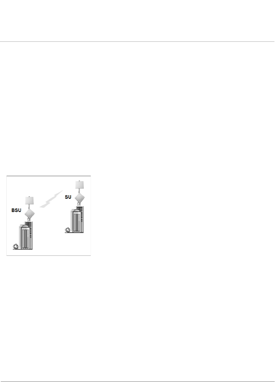
Point-to-Point Link
With a BSU and an SU, it is easy to set up a wireless point-to-point link as depicted in the following figure.
A point-to-point link lets you set up a connection between two locations as an alternative to:
• Leased lines in building-to-building connections
• Wired Ethernet backbones between wireless access points in difficult-to-wire environments
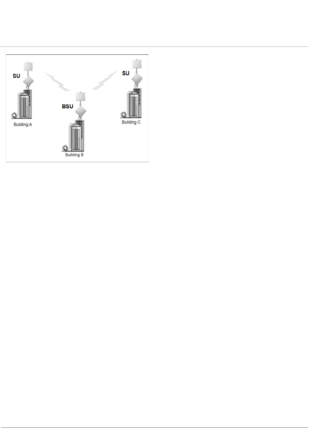
Point-to-Multipoint Network
If you want to connect more than two buildings, you can set up a single point-to-multipoint network with a single BSU and
multiple SUs, as depicted in the following figure.
Introduction MP.11-R Installation and Management
Management and Monitoring Capabilities
13
Up to 250 SUs can be connected to a BSU. If a BSU already has 250 SU, a new SU cannot be connected to the BSU. In
this figure, the system is designed as follows:
• The central building B is equipped with a BSU, connected to either an omni-directional, or a wide angle antenna.
• The two other buildings A and C are both equipped with an SU connected to a directional antenna.
Management and Monitoring Capabilities
There are several management and monitoring interfaces available to the network administrator to configure and
manage the unit:
•Web Interface
•Command Line Interface
•SNMP Management
Web Interface
The Web interface (HTTP) provides easy access to configuration settings and network statistics from any computer on
the network. You can access the Web interface over your network, over the Internet, or with a crossover Ethernet cable
connected directly to your computer’s Ethernet port. See Logging in to the Web Interface.
Command Line Interface
The Command Line Interface (CLI) is a text-based configuration utility that supports a set of keyboard commands and
parameters to configure and manage the unit. You enter command statements, composed of CLI commands and their
associated parameters. You can issue commands from the keyboard for real-time control or from scripts that automate
configuration. See the Tsunami MP.11/QB.11 Reference Manual for more information about the Command Line Interface.
SNMP Management
In addition to the Web interface and the CLI, you also can manage and configure your unit using the Simple Network
Management Protocol (SNMP). Note that this requires an SNMP manager program (sometimes called MIB browser) or a
Network Manager program using SNMP, such as HP OpenView or Castelrock’s SNMPc. The units support several
Management Information Base (MIB) files that describe the parameters that can be viewed and configured using SNMP:
• mib802.mib
•orinoco.mib

Introduction MP.11-R Installation and Management
Management and Monitoring Capabilities
14
• rfc1213.mib
• rfc1493.mib
• rfc1643.mib
Proxim provides these MIB files on the CD included with your unit. You must compile one or more of these MIB files into
your SNMP program’s database before you can manage your unit using SNMP. See the documentation that came with
your SNMP manager for instructions about how to compile MIBs.
NOTE: When you update the software in the unit, you must also update the MIBs to the same release. Because the
parameters in the MIB may have changed, you will not otherwise have full control over the features in the new
release.
The enterprise MIB (orinoco.mib) defines the read and read/write objects you can view or configure using SNMP. These
objects correspond to most of the settings and statistics that are available with the other management interfaces. See the
enterprise MIB for more information; the MIB can be opened with any text editor, such as Microsoft Word, Notepad, and
WordPad. See SNMP Parameters.
IMPORTANT!
Using a serial connection, you can access the unit through a terminal emulation program such as
HyperTerminal. (See “HyperTerminal Connection Properties” in the Tsunami MP.11/QB.11 Reference Manual.)
For all other modes of connection, you will need the IP address of the unit in order to use the Web Interface,
SNMP, or the CLI. See Setting the IP Address with ScanTool for more information.
IMPORTANT!
The remainder of this User Guide discusses installing the unit and managing it using the Web interface only.
For information on managing the unit via the CLI, see the Tsunami MP.11/QB.11 Reference Manual.

MP.11-R Installation and Management
15
2
Installation and Initialization
This chapter describes the steps required to install and mount the unit, and to align the antenna. An antenna cable is
required only when you use the external antenna option. Note that the unit must have either the integrated antenna or
must be connected to an external antenna for its operation. The installation procedure does not include the mounting
and connection of antennas. See the Tsunami MP.11 Antenna Installation Guide for this information.
If you are already familiar with this type of product, you can use the Quick Install Guide for streamlined installation
procedures.
See the following sections:
•Hardware Overview
•Product Package
•Hardware Installation
–Step 1: Choose a Location
–Step 2: Unpack Shipping Box
–Step 3: Assemble the Cable
–Step 4: Determine Proper Mounting Orientation
–Step 5: Assemble Mounting Hardware
–Step 6: Mount the Unit
–Step 7: Plug in the Cables
–Step 8: Power on the Unit
–Step 9: View LEDs
–Step 10: Align the Antenna
–Step 11: Tighten the Cables
–Step 12: Weatherproof the Connectors
–Step 13: Install Documentation and Software
•Initialization
–ScanTool
–Setting the IP Address with ScanTool
•Logging in to the Web Interface

Installation and Initialization MP.11-R Installation and Management
Hardware Overview
16
Hardware Overview
The unit contains a state-of-the-art wireless radio, an optional high-gain performance flat-panel antenna, and Power-
over-Ethernet (the sole means of power for the unit). For further protection, the unit has internal, built-in surge protection.
Power-over-Ethernet
The unit is equipped with a Power-over-Ethernet (PoE) module. Using PoE, you can provide electricity and wired
connectivity to the unit over a single Category 5 cable. Although the power injector that is supplied with the unit is
802.3af-compatible, standard 802.3af-compliant power modules will not properly power the units. Always use the
supplied power injector.
• The PoE integrated module provides –48 VDC over a standard Cat5 Ethernet cable.
• Maximum power supplied to the unit is 20 Watts (when the unit is heating or cooling); the units typically draw less than
7.5 Watts.
• The unit only accepts power on the “extra pairs”, not on the data pairs according the configuration for “midshipman”
power injection, see the IEEE 802.3af standard.
Between 0 and 55° Celsius internal temperature, the unit does not need to regulate its temperature, so the power draw is
generally lower in this temperature range. When the internal temperature gets close to the limits, the unit starts to heat/
cool itself and the power draw increases. Powering while cold triggers a special self-heat mode where the unit is
inoperable until the temperature is above 0° deg Celsius. This is signaled by a solid red LED on the Ethernet connector.
Once the internal temperature is above 0 degrees Celsius, the unit boots normally.
Serial Connection
The serial connection is made with an RJ11 to DB9 connector (also referred to as a “dongle”). Connect the RJ11 end to
the unit and connect the serial (DB9) end to your PC to assist you in aligning the antenna and to issue CLI commands.
See the following figure:
\
Recommended Cable
Function Power (DC) and Ethernet connection
Type Cat5, UV-shielded and outdoor-rated
Impedance 100 ohms
Recommended cables 4 UTP, 24 AWG, UL rated
Maximum Distance 330 feet / 100 meters
Connector type, unit end RJ45 female, weatherized using weatherproof connector
Connector type, power & Ethernet adapter
end
RJ45

Installation and Initialization MP.11-R Installation and Management
Hardware Overview
17
The connections are as follows:
External Antenna Connection
One model of the SU has an integrated antenna; all other models have an external antenna connector (N-type) and no
integrated antenna. For more information about external antennas, see the Antenna Installation Guide.
D-Shell RJ11
1NC
22
34
4NC
5 1 + 3 + 5
66
7NC
8NC
9NC
Installation and Initialization MP.11-R Installation and Management
Product Package
18
Product Package
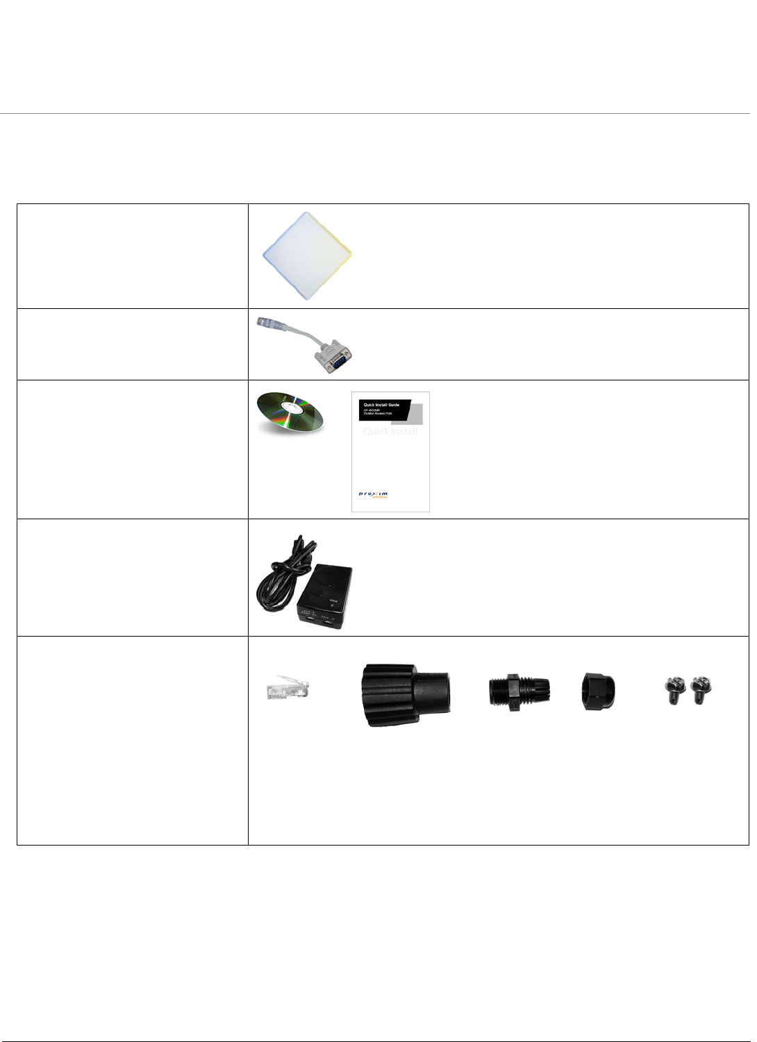
Each shipment includes the items in the following table. Verify that you have received all parts of the shipment.
NOTE: Unless noted in this table, cables are not supplied with the unit.
BS / SS with external antenna
connector
RJ45 to DB9 serial connector
(supplied with BS only) (1 ea.)
Installation CD and Quick Installation
Guide
Power Injector and Cord
Cable Termination Kit Kit includes the following:
a. RJ45 connectors (2)
b. Sealing caps (2)
c. Sealing nut
d. Lock nut
e. Grounding screws
abbecd
Installation and Initialization MP.11-R Installation and Management
Product Package
19
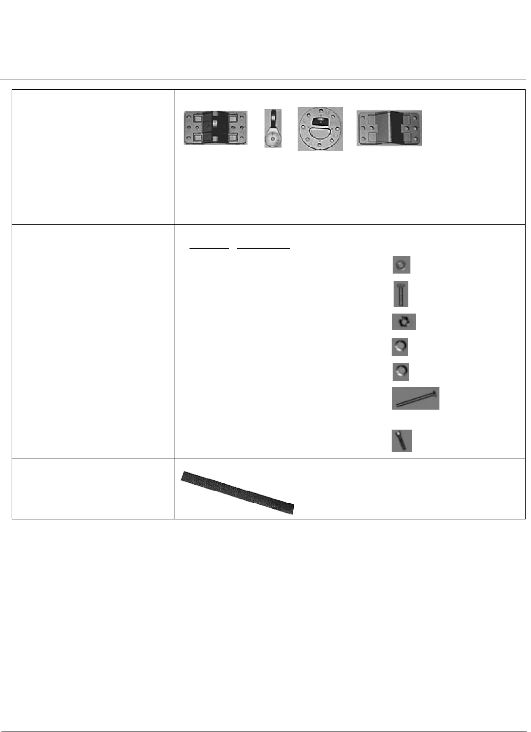
Mounting Kit Kit includes the following:
a. Mounting clamp for wall/pole
b. Extension arm
c. Mounting plate to enclosure
d. Mounting clamp for pole mounting
Mounting Hardware The following mounting hardware, included with the mounting kit:
Rubber Tape Strip
abc d
Quantity Description
6 ea. Plain washer #5/16
2 ea. Hex Cap Screw NC 5/16-18 x 35
2 ea. Nut NC 5/16-18
4 ea. Helical Spring Lock Washer #1/4
4 ea. Helical Spring Lock Washer #1/16
2 ea. Hex Cap Screw NC 5/16-18 x 80
4 ea. 68764, Screw, Machine, Pan,
Philips, 1/4"-20, 5/8"L

Installation and Initialization MP.11-R Installation and Management
Hardware Installation
20
Hardware Installation
This section describes the steps required to install and mount the unit, and to align the antenna. The installation
procedure does not include the mounting and connection of antennas. See the documentation that accompanies the
antenna and the Tsunami MP.11 Antenna Installation Guide for this information.
NOTE:
•The Configure System window provides a selectable Country field that automatically provides the allowed
bandwidth and frequencies for the selected country as well as, where applicable, Dynamic Frequency Selection
(DFS) and Transmit Power Control (TPC).
•Non-US installers should not add an antenna system until the Country is selected, the unit is rebooted, and the
proper power level is configured. The output power level of the final channel selected by DFS scan can be
found in the Event Log.
•Be sure to read the Release Notes file on the product CD as it contains software version and driver information
that may not have been available when this document was produced.
•Equipment is to be used with, and powered by, the power injector provided or by a power injector that meets
these requirements:
–UL-Listed/ITE (NWGQ)
–Limited Power Source Output per UL/IEC 60950
–CE-marked
–Approved for Power-over-Ethernet
–Rated output, 48 Vdc/0.42 A
–Pinout follows 802.3af standard for mid-span devices
See the following sections for installation instructions:
•Step 1: Choose a Location
•Step 2: Unpack Shipping Box
•Step 3: Assemble the Cable
IMPORTANT:
Before installing and using this product, see Safety and Regulatory Compliance Information on the
product CD.
IMPORTANT:
All units must be installed by a suitably trained professional installation technician or by a qualified
installation service.
WARNING:
To ensure proper grounding, use the hole at the bottom point on the back of each unit and the provided
grounding screws to attach a ground wire of at least 10 AWG stranded to each unit. Use proper wire
grounding techniques in accordance with local electric codes.

Installation and Initialization MP.11-R Installation and Management
Hardware Installation
21
•Step 4: Determine Proper Mounting Orientation
•Step 5: Assemble Mounting Hardware
•Step 6: Mount the Unit
•Step 7: Plug in the Cables
•Step 8: Power on the Unit
•Step 9: View LEDs
•Step 10: Align the Antenna
•Step 11: Tighten the Cables
•Step 12: Weatherproof the Connectors
•Step 13: Install Documentation and Software

Installation and Initialization MP.11-R Installation and Management
Hardware Installation
22
Step 1: Choose a Location
To make optimal use of the unit, you must find a suitable location for the hardware. The range of the radio unit largely
depends upon the position of the antenna. Proxim recommends you do a site survey, observing the following
requirements, before mounting the hardware.
• The location must allow easy disconnection of power to the radio if necessary.
• Air must be able to flow freely around the hardware.
• The radio unit must be kept away from vibration and excessive heat.
• The installation must conform to local regulations at all times.
The units are designed to directly mount to a pole. Using the supplied brackets and hardware, you can mount them to a
1.25 inch to 4.5-inch pole (outside diameter). Using just one of the pole mounting brackets, you can mount the units to a
wall or other flat surface.
CAUTION: Proxim recommends the use of a lightning arrestor at the building ingress point. You can purchase the
Proxim Lightning Protector; see the documentation that comes with the unit for more information and
installation instructions.
Step 2: Unpack Shipping Box
1. Unpack the unit and accessories from the shipping box.
2. Note the Ethernet and MAC addresses of the unit, as well as the serial number; these addresses may be used when
configuring the unit.
NOTE: The serial number is required to obtain support from Proxim. Keep this information in a safe place.
Installation and Initialization MP.11-R Installation and Management
Hardware Installation
23
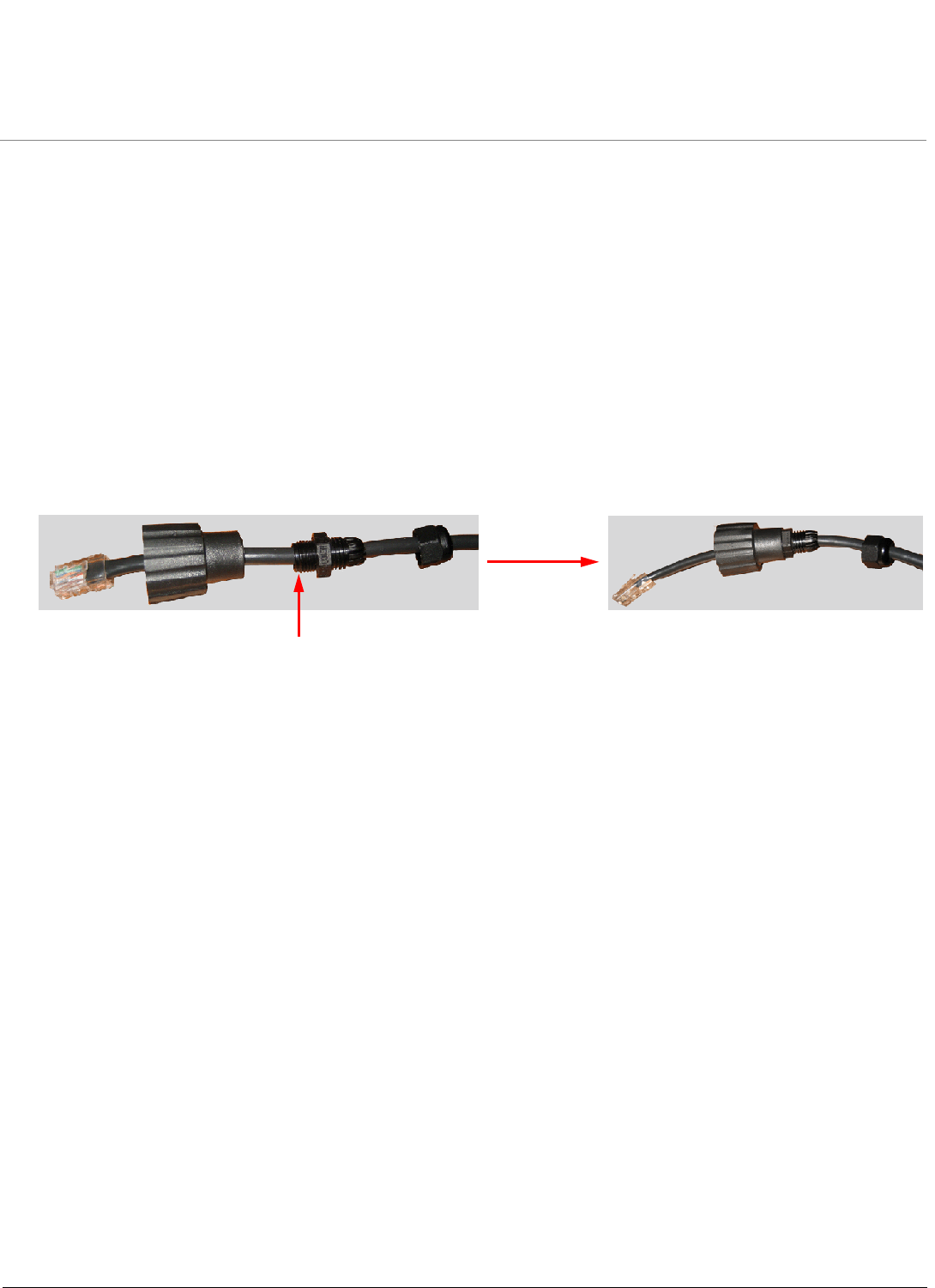
Step 3: Assemble the Cable
You will be attaching an outdoor-rated 24 AWG CAT5 cable (diameter.114 to .250 inches/2.9 to 6.4 mm) (not provided) to
the Power-over-Ethernet port on the back of the unit and waterproofing the assembly later in the installation procedure.
First, you must construct the cable and assemble the waterproofing cable covers as described in the following steps.
Proxim greatly simplifies this assembly process by offering pre-assembled CAT5 cable kits in 25m, 50m, and 75m lengths
(part numbers 69819, 69820, and 69821, respectively).
1. Slide the sealing nut (A) over the bare end of the CAT5 cable.
2. Slide the lock nut (B) over the bare end of the CAT5 cable.
3. Slide the sealing cap (C) over the bare end of the CAT5 cable. Make sure the red rubber gasket is inside the cap.
4. Apply two wraps of 0.5” wide Teflon tape (not supplied with unit) around the threads of the lock nut (B) that will go
inside the sealing cap.
5. Thread the lock nut (B) onto the sealing cap (C), and hand tighten.
6. Terminate the RJ45 connectors (D) to both ends of the CAT5 cable; test for proper wiring (cable should be a straight-
through cable).
NOTE:
•The cable must feed through all parts of the weatherproof cap before the RJ45 is crimped on the outdoor
Ethernet cable.
•The cable between the power injector and the unit must be a straight-through Ethernet cable (without
crossover).
•Due to variance in CAT5 cable diameter, termination techniques of the installer, and the application of proper
tightness of the connectors, it is strongly recommended that all cable connectors are secured by external
weatherproofing. This process will be described in Step 12: Weatherproof the Connectors.
BAC
Apply Teflon
tape here
D
Installation and Initialization MP.11-R Installation and Management
Hardware Installation
24
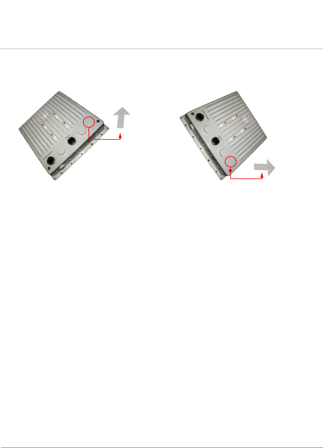
Step 4: Determine Proper Mounting Orientation
1. Locate the arrow on the back of the unit and determine your desired mounting orientation. For vertical polarization
using the integrated antenna, the arrow should be pointing up (perpendicular to the ground). For horizontal
polarization using the integrated antenna, the arrow should be horizontal (parallel to the ground).
Vertical Polarization Horizontal Polarization

Installation and Initialization MP.11-R Installation and Management
Hardware Installation
25
Step 5: Assemble Mounting Hardware
1. Attach the mounting plate (A) using the provided screws and washers (Torque 9 N.m/75 in-lbs), such that the unit’s
antenna will be vertically or horizontally polarized when mounted.
2. Attach the extension arm (B) to mounting piece (A) with the screw, nut, and washers provided, as shown below. The
extension arm gives the unit more possible tilt, letting you adjust for azimuth or elevation over a larger angle.
3. Attach the mounting bracket (C) to extension arm (B) with the screw, nut, and washers provided.
4. Tighten assembly (Torque 15 N.m/130 in-lbs).
A
Torque 9 N.m/75 in-lbs
B
A
B
C
Torque 15 N.m/130 in-lbs
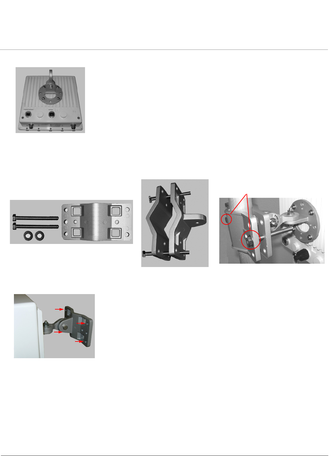
Installation and Initialization MP.11-R Installation and Management
Hardware Installation
26
The following figure shows the full assembly attached to the unit:
Step 6: Mount the Unit
1. To pole-mount, insert screws through bracket F and fasten around the pole to bracket E and secure (Torque 11 N.m/
100 in-lbs).
2. To wall-mount the unit, mount bracket E to a wall using 4 screws (not provided), as shown:
F
FE
FTorque 11 N.m/100 in-lbs
2 screws
Installation and Initialization MP.11-R Installation and Management
Hardware Installation
27
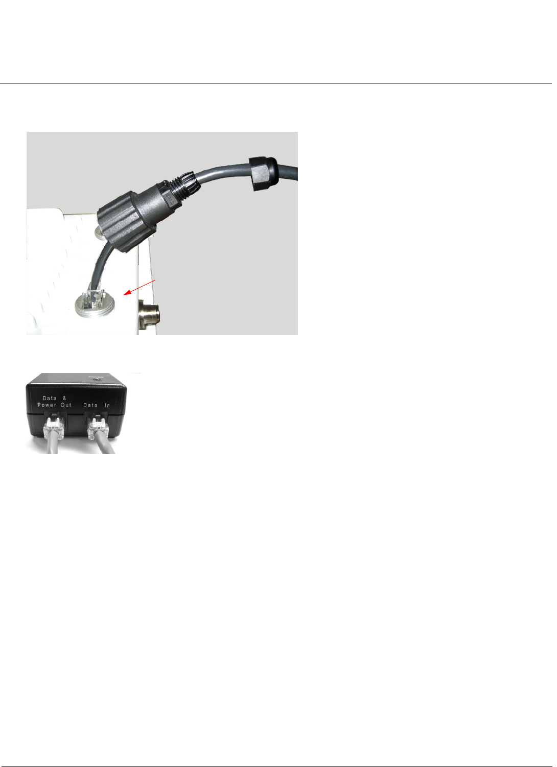
Step 7: Plug in the Cables
1. Plug one end of the CAT5 cable (A) into the RJ45 jack of the unit (B).
2. Connect the free end of the CAT5 cable to the “Data and Power Out” port on the power injector.
3. To connect the unit through a hub or a switch to a PC, connect a straight-through Ethernet cable between the
network interface card in the PC and the hub, and between the hub and the RJ45 “Data In” port on the PoE adapter.
To connect the unit directly to a PC, connect a cross-over Ethernet cable between the network interface card in the
PC and the RJ45 “Data In” port on the power injector.
A
B
Installation and Initialization MP.11-R Installation and Management
Hardware Installation
28
Step 8: Power on the Unit
Once you have connected the power injector to the Ethernet cabling and plugged the power injector cord into an AC
outlet, the unit is powered on. There is no ON/OFF switch on the unit. To remove power, unplug the AC cord from the AC
outlet or disconnect the RJ45 connector from the “Data and Power Out” port on the power injector.
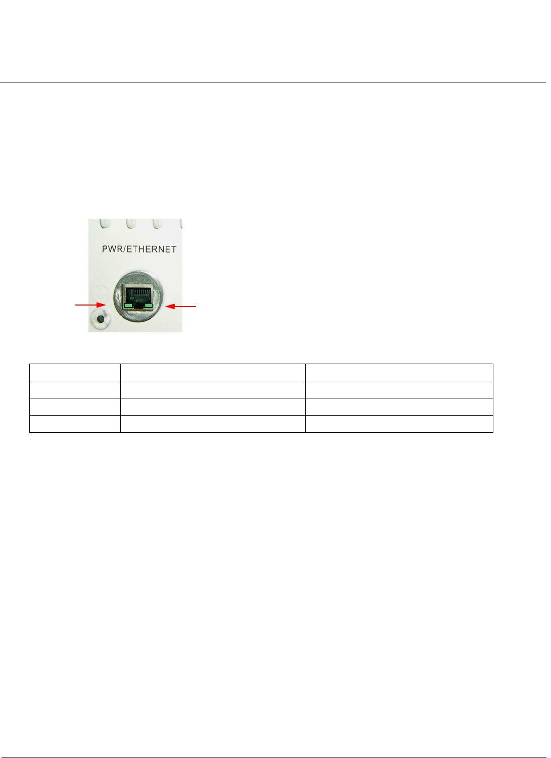
Step 9: View LEDs
When the unit is powered on, it performs startup diagnostics. When startup is complete, the LEDs show the unit’s
operational state. The LEDs are present at the unit’s Ethernet connector.
LEDs exhibit the following behavior:
LED State Radio LED Power/Ethernet LED
Red Power is on; unit is self-heating. —
Flashing Green Wireless link is being established. Power is on, Ethernet link is down.
Solid Green Wireless link has been established. Power is on, Ethernet link is up.
Ethernet
LED
RF
LED
Installation and Initialization MP.11-R Installation and Management
Hardware Installation
29
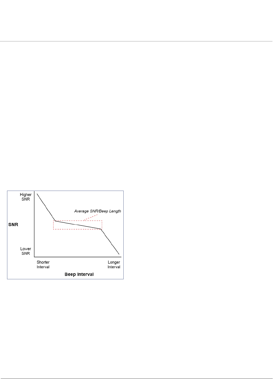
Step 10: Align the Antenna
Antenna alignment is the process of physically aligning the antenna of the radio receiver and transmitter to have the best
possible link established between them. The antenna alignment process is usually performed during installation and after
major repairs.
If you are installing external antennas, consult the documentation that accompanies the antenna for installation
instructions. Note that you must weatherproof the antenna connectors as described in Step 12: Weatherproof the
Connectors.
The unit has an audible antenna alignment tool that can be activated by plugging in the supplied serial dongle (supplied
with the BSU) or by issuing the CLI command for antenna alignment. The CLI command causes both audible and
numerical feedback as the CLI shows the running Signal-to-Noise Ratio (SNR) values twice a second.
The output from the beeper for antenna alignment consists of short beeps with a variable interval. The interval changes
with the SNR level to assist in correctly aligning the antenna. An increase in signal level is indicated by a shorter interval
between beeps; a reduction in signal level results in beeps longer apart.
To allow for precise antenna alignment, small changes in SNR result in large changes in the beep period. The alignment
process averages the SNR, which is represented by an average length beep. When a higher SNR is received, the beep
period is made shorter, dependent upon the difference to the average. A lower SNR results in a longer period between
beeps.
The first five steps around the average are represented by a large change and all following steps are a small change.
This acts as if a magnifying glass is centered around the average SNR and the values next to the average are
significantly different.
When the antenna is aimed, the beep intuitively represents whether the SNR is rising or falling: the higher the SNR rises,
the shorter the period the beep is heard and the higher the frequency of the beep.
After the position of the antenna has been changed, SNR averaging settles at the new value and the beeping returns to
the average length so the antenna can again be aimed for rising SNR.
Aiming is complete if moving in any direction results in a falling SNR value (which can be heard as longer periods
between beeps).
NOTES:
•Antenna alignment for the Base Station is useful only for a point-to-point link.
•The range of the average SNR has been limited to values from 5 to 43; therefore, anything over 43 always
results in a short period between beeps and values below 5 always have a long period.

Installation and Initialization MP.11-R Installation and Management
Hardware Installation
30
•The Antenna Alignment Display (AAD) CLI command is disabled automatically 30 minutes after it is enabled to
remove the load of extra messages on the wireless interface. The default telnet timeout is 900 seconds (15
minutes). If AAD must run for the entire 30 minutes, change the default telnet timeout value to a value greater
than 30 minutes (greater than 1800 seconds). This restriction is for telnet connections only and not for the serial
interface. The serial interface never times out; however, the AAD command does still time out.
Antenna Alignment Commands
•set aad enable local: Enables display of the local SNR. Local SNR is the SNR measured by the receiver at the
near end.
•set aad enable remote: Enables display of the remote SNR. Remote SNR is the SNR as measured by the
receiver at the far end.
•set aad enable average: Enables display of the average SNR. The average SNR is the average of the local and
remote SNR.
•set aad disable: Disables Antenna Alignment Display (Ctrl-C also disables AAD).
Installation and Initialization MP.11-R Installation and Management
Hardware Installation
31
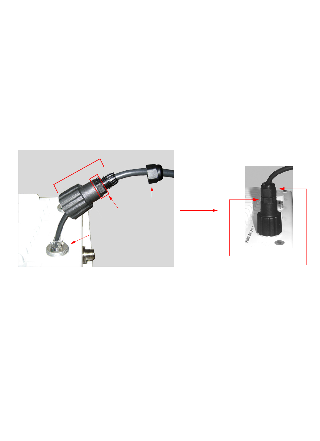
Step 11: Tighten the Cables
1. Apply two wraps of Teflon tape around the threads of the unit’s RJ45 jack (A) in a clockwise direction.
2. Make sure that the red rubber gasket is still seated in the sealing cap of the sealing cap/lock nut assembly (B);
3. Slide the sealing cap/lock nut assembly (B) over the RJ45 jack (A) and thread onto enclosure. Hand tighten first, then
use a pipe wrench or similar tool to tighten one more quarter turn.
CAUTION: Do not over-tighten!
4. Tighten the lock nut (C) (Torque 4 N.m/35 in-lbs).
5. Thread the sealing nut (D) onto the sealing cap/lock nut assembly (B) and tighten (Torque 3 N.m/25 in-lbs).
CAUTION: The lock nut (C) on the sealing cap/lock nut assembly (B) must be fully tightened over the RJ45 connector
before the sealing nut (D) is fully tightened. Otherwise, the Ethernet cable may twist and damage.
D
B
A (Apply Teflon
C
Torque 3 N.m/25 in-lbs
Torque 4 N.m/35 in-lbs
tape here)
Installation and Initialization MP.11-R Installation and Management
Hardware Installation
32
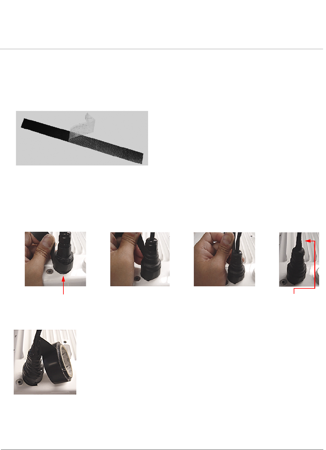
Step 12: Weatherproof the Connectors
After you have fully assembled and tightened the cable, use the provided self-fusing, rubber-based tape strip and
electrical tape (not provided; Proxim recommends Scotch™ Super 33+ Vinyl Electrical Tape) to seal the connection, as
follows.
1. Remove the film liner from the rubber-based tape strip, and stretch the tape until it is approximately half of its original
width. This activates the self-fusing action of the tape, which will set up over time to create a single, waterproof mass.
2. Stretch and wrap the tape around the connector tightly, starting below the connector cap and against the unit and
wrapping in a clockwise direction. Wrap the tape once around the base of the connector cap (A). Continue to wrap the
tape spirally around the connector in a clockwise direction, maintaining a 50% width overlap (B). Continue wrapping
the tape spirally upward (C) until the tape extends onto the cable and you have used the entire length of tape. Seal the
tape tightly against the connector and the cable (D).
NOTE: Be sure to wrap the tape in a clockwise direction; wrapping the tape in a counterclockwise direction may
loosen up the connector.
3. In the same manner as described in Step 2 above, apply a layer of black electrical tape (not provided) over the rubber-
based tape for further protection. Make sure the electrical tape also extends beyond the rubber-based tape to seal it.
4. Repeat the weatherproofing procedure for other connectors as appropriate.
ABCD
Start below connector cap Continue onto cable

Installation and Initialization MP.11-R Installation and Management
Hardware Installation
33
Step 13: Install Documentation and Software
To install the documentation and software on a computer or network:
1. Place the CD in a CD-ROM drive. The installer normally starts automatically. (If the installation program does not start
automatically, click setup.exe on the installation CD.)
2. Click the Install Software and Documentation button and follow the instructions displayed on the installer windows.
The following documentation and software products are installed:
– Available from Start > All Programs > Tsunami > MP.11 [Model Name]:
• Documentation (in Docs subdirectory):
– Installation and Management Guide
– Quick Installation Guide
– Reference Manual
– Safety and Regulatory Guide
– Recommended Antenna Guide
– Antenna Installation Guide
• Online Help
• Scan Tool (in Scan Tool subdirectory)
• TFTP Server (in TFTP Server subdirectory)
NOTE: All of these items are also available from C:\Program Files\Tsunami\MP.11 [Model Name].
– Available from C:\Program Files\Tsunami\MP.11 [Model Name]:
• Documentation (in Docs folder): See list above
• Help files (in Help folder; click on index.htm to access)
• TFTP Server and Scan Tool program (in Extras folder)
•MIBs (in MIBs folder)
Installation and Initialization MP.11-R Installation and Management
Initialization
34
Initialization
Connecting to the unit requires either:
• A direct physical connection with an Ethernet cross-over cable or with a serial RS232C cable
• A network connection
Connecting with a serial connection, allows you to configure and manage the unit with the CLI. Connecting with the other
connections allows you to use of the Web Interface and SNMP in addition to the CLI.
Using a serial connection, you can access the unit through a terminal emulation program such as HyperTerminal. (See
“HyperTerminal Connection Properties” in the Tsunami MP.11/QB.11 Reference Manual.)
For all other modes of connection, you will need the IP address of the unit in order to use the Web Interface, SNMP, or the
CLI. Because each network is different, an IP address suitable for your network must be assigned to the unit. You must
know this IP address to configure and manage the unit through its Web Interface, SNMP, or the CLI. The unit can use
either a static or dynamic IP address. The unit either obtains its IP address automatically through DHCP (dynamic IP
address) or it must be set manually (static IP address).
ScanTool
With ScanTool (a software utility that is included on the product installation CD), you can find out the current IP address of
the unit and, if necessary, change it so that is appropriate for your network. The units are shipped with the static IP
address 10.0.0.1 configured.
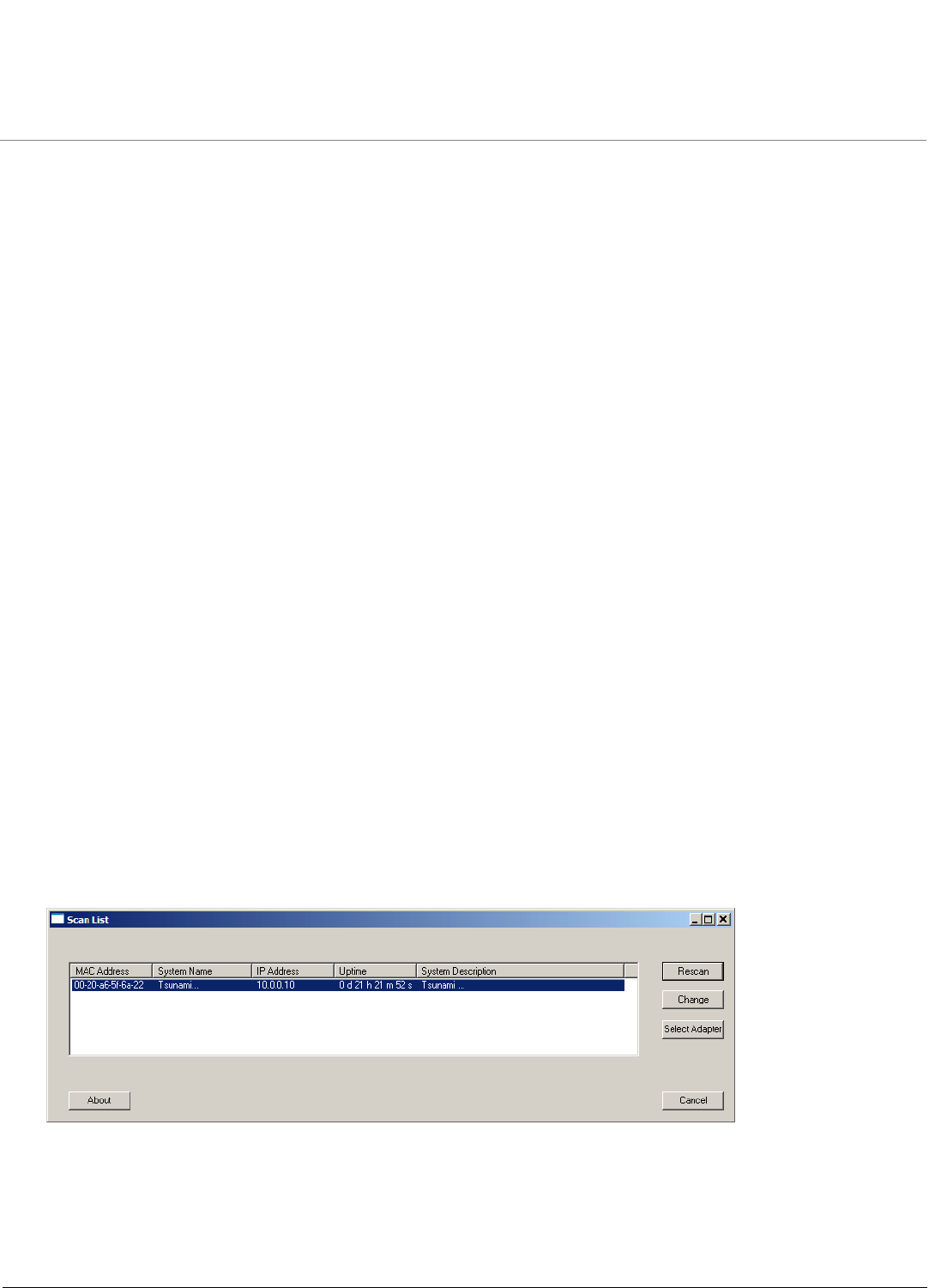
ScanTool lets you find the IP address of a Tsunami MP.11-R product by referencing the MAC address in a Scan List, or to
assign an IP address if the correct one has not been assigned. The tool automatically detects the units installed on your
network segment, regardless of IP address, and lets you configure each unit’s IP settings. In addition, you can use
ScanTool to download new software to a unit that does not have a valid software image installed.
Setting the IP Address with ScanTool
To discover and set/change the IP address of the unit:
1. Run ScanTool on a computer connected to the same LAN subnet as the unit, or a computer directly connected to the
unit with a cross-over Ethernet cable. Double-click the ScanTool icon on the Windows desktop to launch the program.
If the icon is not on your desktop, click Start > All Programs > Tsunami > MP.11 [Model Name]> Scan Tool.
ScanTool scans the subnet for MP.11-R units and displays a list of the units it finds in the Scan List window (shown
below). If necessary, click Rescan to re-scan the subnet and update the display.
You can assign a new IP address to one unit, even if more than one unit has the same (default) IP address 10.0.0.1,
but the new IP address must be unique to allow use of the management interfaces.
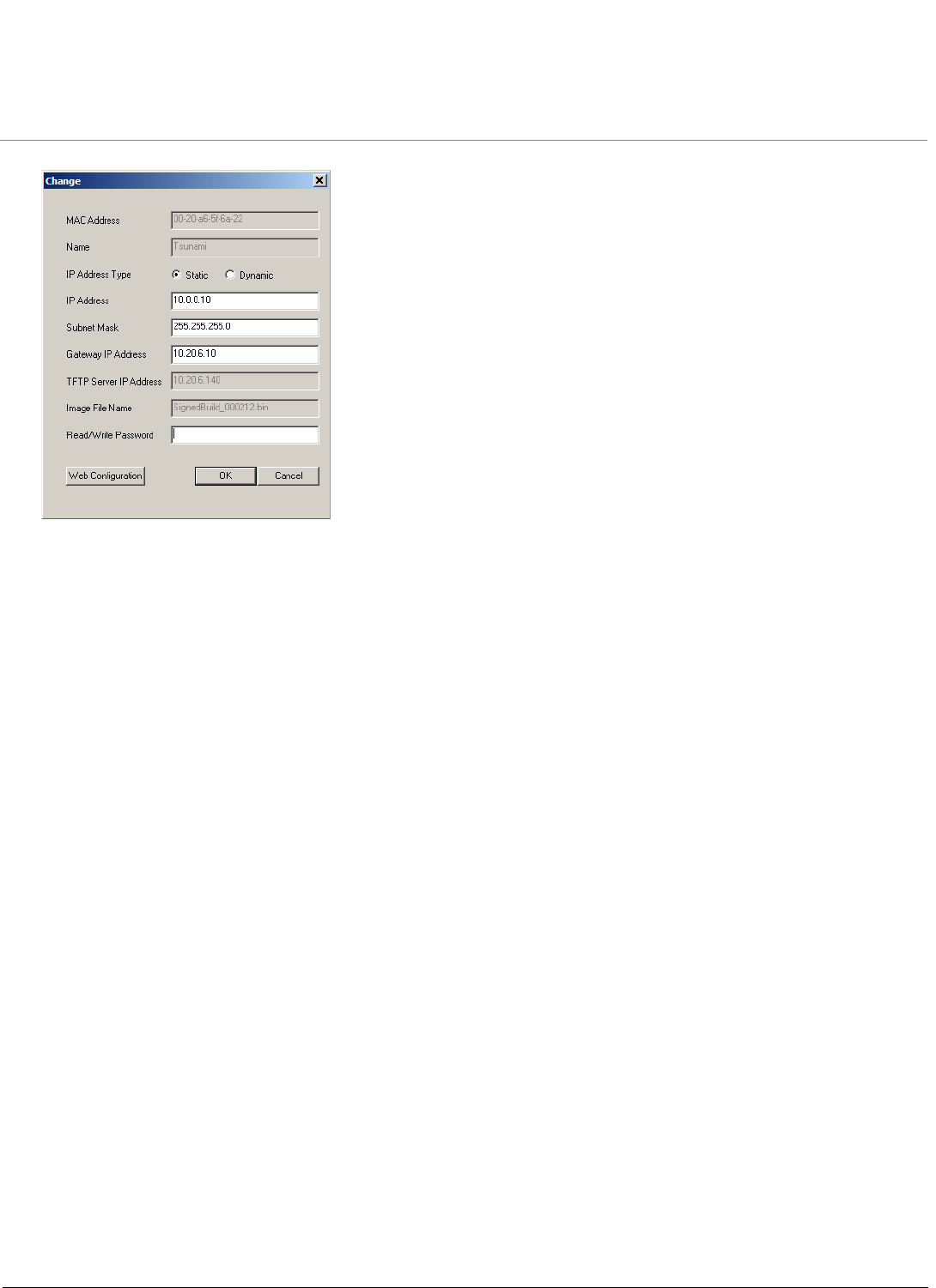
2. Select the unit for which you want to set the IP address and click Change. The Change dialog window is displayed,
as shown below.
Installation and Initialization MP.11-R Installation and Management
Initialization
35
3. To set the IP address manually, ensure that Static is selected as the IP Address Type and fill in the IP Address and
Subnet Mask suitable for the LAN subnet to which the unit is connected.
To set the IP address dynamically, ensure that Dynamic is selected as the IP Address Type. The unit will request its
IP address from a DHCP server on your network.
4. Enter the Read/Write Password (the default value is public) and click OK to confirm your changes. The respective
unit reboots to make the changes effective.
Installation and Initialization MP.11-R Installation and Management
Logging in to the Web Interface
36
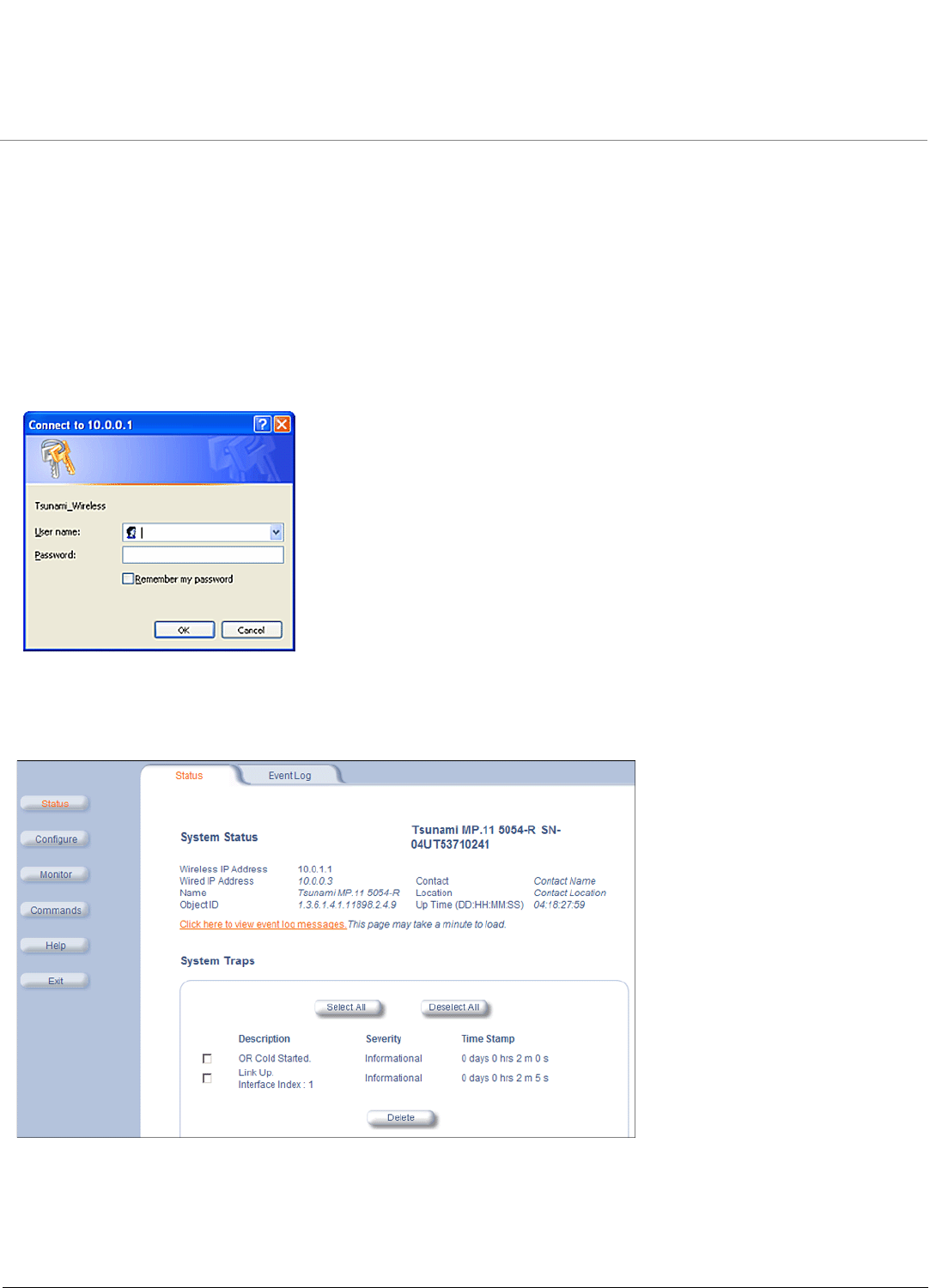
Logging in to the Web Interface
The Web Interface provides a graphical user interface through which you can easily configure and manage the unit. This
section describes only how to access the Web Interface.
To use the Web Interface, you need only the IP address of the unit. (See Setting the IP Address with ScanTool for
details).
NOTE: If the connection is slow or you are not able to connect, use the Internet Explorer Tools option to ensure you are
not using a proxy server for the connection with your Web browser.
To access the unit with a Web browser, start your Web browser and enter the IP address of the unit. The Web address
must appear as http://<ip address> (for example, http://10.0.0.1). A window such as the following is displayed.
Do not fill in the User Name, enter only the password and click OK. The default password is public.
The System Status window is displayed. To find out more about the information presented in this window, see the Status
chapter.
You now have access to the unit’s Web Interface. The remainder of this manual describes configuring and monitoring the
unit using this interface.
MP.11-R Installation and Management
37
3
System Overview
This chapter provides an overview of the system. See the following sections:
•Changing Basic Configuration Information
–Country and Related Settings
–Dynamic Frequency Selection (DFS)
–Transmit Power Control
•SU Registration
•Dynamic Data Rate Selection (DDRS)
•Virtual Local Area Networks (VLANs)
•Quality of Service (QoS)
–Concepts and Definitions
Changing Basic Configuration Information
To view or change basic system information, click the Configure button on the left side of the Web interface window,
then click the System tab. See System Parameters for detailed information about the fields and selections in this
window.
NOTE: System Name by default contains the actual model number. The following screenshot is for information only.
Country and Related Settings
The unit’s Configure System window provides a selectable Country field that automatically provides the allowed
bandwidth and frequencies for the selected country.
Units sold only in the United States are pre-configured to scan and display only the outdoor frequencies permitted by the
FCC. No other Country can be configured. Units sold outside of the United States support the selection of a Country by
the professional installer.

System Overview MP.11-R Installation and Management
Changing Basic Configuration Information
38
NOTE: Non-US installers should not add an antenna system until the Country is selected, the unit is rebooted, and the
proper power level is configured. The output power level of the final channel selected by DFS scan can be found
in the Event Log.
The Dynamic Frequency Selection (DFS) feature is enabled automatically when you choose a country with a regulatory
domain that requires it. The Transmit Power Control (TPC) feature is always available.
Click Configure > System; then select the appropriate country for your regulatory domain from the Country drop-down
box.
Continue configuring settings as desired; then click Commands > Reboot to save and activate the settings. Alternatively,
if you want to save the configuration settings to the flash memory but not activate the settings, use the save config CLI
command.
Dynamic Frequency Selection (DFS)
NOTE: Dynamic Frequency Selection (DFS) only applies to the Tsunami MP.11 5054-R.
The Tsunami MP.11-R supports Dynamic Frequency Selection (DFS) for FCC, IC, and ETSI regulatory domains per FCC
Part 15 Rules for U-NII devices, IC RSS-210, and ETSI EN 301-893 and 302-502 regulations, respectively. These rules
and regulations require that 802.11a devices use DFS to prevent interference with radar systems and other devices that
already occupy the 5 GHz band.
During boot-up, the unit scans the available frequency and selects a channel that is quiet and free of radar interference. If
the unit subsequently detects radar interference on its channel, it rescans to find a better channel. Upon finding a new
channel, the unit waits 60 seconds to detect radar interference; if it finds no interference, it commences normal operation.
(In Canada, if radar was previously detected on the selected channel, the unit waits 600 seconds before commencing
normal operation if the selected channel frequency is in the 5600 - 5650 MHz range)
If you are using the unit in a country and band that require DFS, keep in mind the following:
• DFS is not a configurable parameter; it is always enabled and cannot be disabled.
• You cannot manually select the device’s operating channel; you must let the unit select the channel. You may make
channels unavailable by manually “blacklisting” them and preventing those channels being selected, in accordance
with local regulations or interference. You can also display the Channel Blacklist Table to view the channels that have
been blacklisted by the AP due to radar detection.
• In compliance with FCC regulations, the unit uses ATPC (Automatic Transmit Power Control) to automatically adapt
transmit power when the quality of the link is more than sufficient to maintain a good communication with reduced
transmit power. See Transmit Power Control for more information.
Dynamic Frequency Selection (DFS) is enabled automatically based upon the country and band you select. You can tell
DFS is in use because the frequency selection field displays only the DFS-selected frequency. DFS scans all available
frequencies, starting with the DFS preferred channel (when configured) and skipping blacklisted channels, to select the
operating frequency automatically.
A country selection with DFS enabled causes the Base Station to come up in scan mode. It scans the available
frequencies and channels to avoid radar and selects a channel with the least interference.
NOTE: Scanning is performed only on the frequencies allowed in the regulatory domain of the country selected when it is
required for radar detection and avoidance.
The SU also comes up in scan mode to scan all available frequencies to find a BSU with which it can register. Scanning
may take several minutes. After establishing a wireless link, the wireless LED stops flashing and continues to shine
green.
NOTE: Because DFS may need to scan for radar on multiple channels, you must allow a sufficient amount of time for the
units to start up. This is considerably longer than when the unit is not using DFS. This is expected behavior.
Startup time is within four minutes if no radar is detected, but up to one minute is added for every selected
channel that results in radar detection.

System Overview MP.11-R Installation and Management
Changing Basic Configuration Information
39
DFS is required for three purposes:
1. Radar avoidance both at startup and while operational. To meet these requirements, the BSU scans available
frequencies at startup for the presence of a radar signal on all available frequencies. If a radar signal is detected on
any DFS enabled channel, the system will blacklist the channel for a period of 30 minutes in accordance with FCC, IC,
and ETSI regulations. Once fully operational on a frequency, the BSU actively monitors the occupied frequency for
radar interference. If radar interference is detected, the BSU blacklists the channel, logs a message and rescans to
find a new frequency free of radar interference.
Radar detection is performed only by the BSU and not by the SU. When an SU is set to a country in which DFS is
used, it scans all available channels upon startup looking for a BSU that best matches its connection criteria (such as
Base Station System Name, Network Name, and Shared Secret). The SU connects to the BSU automatically on
whatever frequency the BSU has selected. Because of this procedure, it is best to set up the BSU and have it fully
operational before installing the SU, although this is not required. If a BSU rescans because of radar interference, the
SU loses its wireless link. The SU waits 30 seconds (when the Mobility feature is enabled, the SU starts scanning for
a BSU instantly rather than waiting 30 seconds); if it finds that it could not receive the BSU in this amount of time, it
rescans the available frequencies for an active BSU.
2. Guarantee the efficient use of available frequencies by all devices in a certain area. To meet this requirement, the
BSU scans each available frequency upon startup and selects a frequency based upon the least amount of noise and
interference detected. This lets multiple devices operate in the same area with limited interference. This procedure is
done only at startup; if another non-radar device comes up on the same frequency, the BSU does not detect this or
rescan because of it. It is expected that other devices using these frequencies also are in compliance with country
regulations, so this should not happen.
3. Uniform Channel Spreading. To meet this requirement, the MP.11-R randomly selects operating channel from the
channels with least interference. If the DFS Preferred Channel is configured, the unit begins by scanning that channel
for radar. If no radar is detected, the unit makes this channel operational. If radar is detected, the unit blacklists that
channel and scans other available channels for the one with least interference. This implements the Uniform Channel
Spreading requirement by either automatically selecting the channel with least interference or allowing the installer to
manually select a channel with least interference from a channel plan.
Transmit Power Control
Transmit Power Control is a manual configuration selection to reduce the unit’s output power. The maximum output
power level for the operating frequency can be found in the event log of the unit’s embedded software.
ATPC (Automatic Transmit Power Control) is a feature to automatically adapt transmit power when the quality of the link
is more than sufficient to maintain a good communication with reduced transmit power. This feature is required for FCC
DFS. It works by monitoring the quality of the link and reducing the output power of the radio by up to 6 dB when good link
quality can still be achieved. When link quality reduces, the output power is automatically increased up to the original
power level to maintain a good link. For a full discussion of DFS, see Dynamic Frequency Selection (DFS) abvoe.
By default, the unit lets you transmit at the maximum output power that the radio can sustain for data rate and frequency
selected. However, with Transmit Power Control (TPC), you can adjust the output power of the unit to a lower level in
order to reduce interference to neighboring devices or to use a higher gain antenna without violating the maximum
radiated output power allowed for your country. Also, some countries that require DFS also require the transmit power to
be set to a 6 dB lower value than the maximum allowed EIRP when link quality permits, as part of the DFS requirements.
NOTE: When the system is set to transmit at the maximum power, professional installers must ensure that the maximum
EIRP limit is not exceeded. To achieve this, they may have to add attenuation between the device and the
antenna when a high gain antenna is used.
For 4954-R models: to comply with FCC Part 90 regulations when using an external antenna, a TPC value of -3
dB is required regardless of antenna size, and a larger TPC value may be required to limit the total EIRP to 29
dBm or less. For 4954-R models that have an integrated flat-panel antenna, a TPC of -9 dB must be used to
comply with FCC Part 90 regulations.
CAUTION: To insure proper operation on 4954-R models, TPC values greater than -9 dB should be avoided.

System Overview MP.11-R Installation and Management
Changing Basic Configuration Information
40
You can see your unit’s current output power for the selected frequency in the event log. The event log shows the
selected power for all data rates, so you must look up the relevant data rate to determine the actual power level.
NOTE: This feature only lets you decrease your output power; you cannot increase your output power beyond the
maximum the radio allows for your frequency and data rate.
See System Parameters to configure Country. See Interface Parameters to configure Transmit Power Control.

System Overview MP.11-R Installation and Management
SU Registration
41
SU Registration
The list of parameters you must configure for registration of the SU on a BSU are:
• Network Name
• Base Station System Name (when used; otherwise, leave blank)
•Network Secret
• Encryption (when used)
• Frequency Channel (when available)
See System Parameters to see the description of these fields and to configure them.
NOTES:
•The frequency channel must be the same for the BSU and the SU in order to register the SU when roaming is
not enabled and DFS is not required.
•Channel Bandwidth and Turbo mode (when available) must be the same for the BSU and SU in order to register
the SU.
•Roaming will automatically select a channel on the SU corresponding to the BSU channel. Roaming is the
procedure in which an SU terminates the session with the current BSU and starts the registration procedure with
another BSU when it finds the quality of the other BSU to be better.

System Overview MP.11-R Installation and Management
Dynamic Data Rate Selection (DDRS)
42
Dynamic Data Rate Selection (DDRS)
The WORP Dynamic Data Rate Selection (DDRS) lets the BSU and SUs monitor and calculate the remote average
signal-to-noise ratio (SNR) and adjust the transmission data rate to an optimal value to provide the best possible
throughput according to the current communication conditions and link quality during run-time.
Each frame received in the WORP protocol reports the signal and noise level in dBm at which the sender received the
previous frame from the receiver, and provides the values to calculate the SNR in dB. SNR is calculated according to this
formula then averaged:
SNR [dB] = signal level [dBm] – noise level [dBm]
Both the BSU and the SUs monitor the remote SNR. The BSU monitors and calculates the average remote SNR for each
SU that is registered. An SU monitors and calculates the average remote SNR for the BSU.
DDRS is enabled or disabled on the BSU only. This operation requires the BSU to be rebooted. After rebooting, the BSU
sends a multicast announcement to all SUs to begin the registration process. During registration, an SU is informed by
the BSU whether DDRS is enabled or disabled and it sets its DDRS status accordingly.
There are two DDRS data rates that need to be configured when DDRS is enabled:
•Default DDRS Data Rate (ddrsdefdatarate): The data rate at which the BSU starts communication with all SUs to
begin the registration process (the default is 6 Mbps).
•Maximum DDRS Data Rate (ddrsmaxdatarate): The maximum data rate at which the device (BSU or SU) can
operate (the default is 54 Mbps).
NOTE: The default (BSU only) and maximum (BSU and SU) DDRS data rate values must be configured in the BSU and
SUs separately through the CLI or the SNMP interface.
See Interface Parameters to configure DDRS.

System Overview MP.11-R Installation and Management
Virtual Local Area Networks (VLANs)
43
Virtual Local Area Networks (VLANs)
Virtual Local Area Networks (VLANs) are logical groupings of network hosts. Defined by software settings, other VLAN
members or resources appear (to connected hosts) to be on the same physical segment, no matter where they are
attached on the logical LAN or WAN segment. They simplify allowing traffic to flow between hosts and their frequently-
used or restricted resources according to the VLAN configuration.
Tsunami MP.11-R units are fully VLAN-ready; however, by default, VLAN support is disabled. Before enabling VLAN
support (by assigning a VLAN Management ID), certain network settings should be configured and network resources
such as VLAN-aware switches should be available, dependent upon the type of configuration.
VLANs are used to conveniently, efficiently, and easily manage your network in the following ways:
• Manage VLAN configuration from a single window
• Define groups
• Reduce broadcast and multicast traffic to unnecessary destinations
– Improve network performance and reduce latency
• Increase security
– Secure network restricts members to resources on their own VLAN
VLAN tagged data is collected and distributed through a unit’s Ethernet interface. The units can communicate across a
VLAN-capable switch that analyzes VLAN-tagged packet headers and directs traffic to the appropriate ports when the
units are working in their Transparent mode.
VLAN features can be managed via:
• The BSU’s Web interface
• The Command Line Interface (see “Command Line Interface” in the Tsunami MP.11/QB.11 Reference Manual)
• SNMP (see the MIBs provided on the product CD)
For more information about VLAN configuration, see VLAN Parameters (BSU Only; Bridge Mode Only).

System Overview MP.11-R Installation and Management
Quality of Service (QoS)
44
Quality of Service (QoS)
The Quality of Service (QoS) feature is based on the 802.16 standard and defines the classes, service flows, and packet
identification rules for specific types of traffic. QoS main priority is to guarantee a reliable and adequate transmission
quality for all types of traffic under conditions of high congestion and bandwidth over-subscription.
Concepts and Definitions
The software supports QoS provisioning from the BSU only. You may define different classes of service on a BSU that
can then be assigned to the SUs that are associated, or that may get associated, with that BSU.
The software provides the ability to create, edit, and delete classes of service that are specified by the following hierarchy
of parameters:
• Packet Identification Rule (PIR) – up to 64 rules, including 17 predefined rules
• Service Flow class (SFC) – up to 32 SFs, including 7 predefined SFCs; up to 8 PIRs may be associated per SFC
• Priority for each rule within each SF class – 0 to 255, with 0 being lowest priority
• QoS class – up to 8 QoS classes, including 4 predefined classes; up to 4 SFCs may be associated per QoS class
Packet Identification Rule (PIR)
A Packet Identification Rule is a combination of parameters that specifies what type of traffic is allowed or disallowed.
The software allows to create up to 64 different PIRs, including 17 predefined PIRs. It provides the ability to create, edit,
and delete PIRs that contain none, one, or more of the following classification fields:
• Rule Name
• IP ToS (Layer 3 QoS identification)
• IP Protocol List containing up to 4 IP protocols
• 802.1p tag (layer 2 QoS identification)
• Up to 4 pairs of Source IP address + Mask
• Up to 4 pairs of Destination IP address + Mask
• Up to 4 source TCP/UDP port ranges
• Up to 4 destination TCP/UDP port ranges
• Up to 4 source MAC addresses
• Up to 4 destination MAC addresses
•VLAN ID
• Ether type (Ethernet protocol identification)
A good example is provided by the 17 predefined PIRs. Note that these rules help to identify specific traffic types:
1. All – No classification fields, all traffic matches
2. Cisco VoIP UL
a. Protocol Source Port Range (16,000-32,000)
b. IP Protocol List (17 = UDP)
3. Vonage VoIP UL
a. Protocol Source Port Range (8000-8001, 10000-20000)
b. IP Protocol List (17 = UDP)
4. Cisco VoIP DL
a. Protocol Destination Port Range (16,000-32,000)
b. IP Protocol List (17 = UDP)
5. Vonage VoIP DL

System Overview MP.11-R Installation and Management
Quality of Service (QoS)
45
a. Protocol Destination Port Range (8000-8001, 10000-20000)
b. IP Protocol List (17 = UDP)
6. TCP
a. IP Protocol List (6)
7. UDP
a. IP Protocol List (17)
8. PPPoE Control
a. Ethertype (type 1, 0x8863)
9. PPPoE Data
a. Ethertype (type 1, 0x8864)
10.IP
a. Ethertype (type 1, 0x800)
11. ARP
a. Ethertype (type 1, 0x806)
12.Expedited Forwarding
a. IP TOS/DSCP (low=0x2D, high=0x2D, mask = 0x3F)
13.Streaming Video (IP/TV)
a. IP TOS/DSCP (low=0x0D, high=0x0D, mask = 0x3F)
14.802.1p BE
a. Ethernet Priority (low=0, high=0) (this is the equivalent of the User Priority value in the TCI (Tag Control
Information) field of a VLAN tag)
15.802.1p Voice
a. Ethernet Priority (low=6, high=6) (this is the equivalent of the User Priority value in the TCI (Tag Control
Information) field of a VLAN tag)
16.802.1p Video
a. Ethernet Priority (low=5, high=5) (this is the equivalent of the User Priority value in the TCI (Tag Control
Information) field of a VLAN tag)
17.L2 Broadcast/Multicast
a. Ethernet Destination (dest = 0x80000000, mask = 0x80000000)
Note that two different VoIP rule names have been defined for each direction of traffic, Uplink (UL) and Downlink (DL),
(index numbers 2 to 5). This has been done to distinguish the proprietary nature of the Cisco VoIP implementation as
opposed to the more standard Session Initiation Protocol (SIP) signaling found, for example, in the Vonage-type VoIP
service.
Service Flow Class (SFC)
A Service Flow class defines a set of parameters that determines how a stream of application data that matches a certain
classification profile will be handled. The software allows to create up to 32 different SFs, including seven predefined
SFs. The software provides the ability to create, edit, and delete SFs that contain the following parameters and values:
• Service flow name
• Scheduling type – Best Effort (BE); Real-Time Polling Service (RtPS)
• Service Flow Direction – Downlink (DL: traffic from BSU to SU); Uplink (UL: traffic from SU to BSU)
• Maximum sustained data rate (or Maximum Information Rate, MIR) – specified in units of 1 Kbps from 8 Kbps up to he
maximum rate of 108000 Kbps per SU
• Minimum reserved traffic rate (or Committed Information Rate, CIR) – specified in units of 1 Kbps from 0 Kbps up to
the maximum rate of 10000 Kbps per SU

System Overview MP.11-R Installation and Management
Quality of Service (QoS)
46
• Maximum Latency – specified in increments of 5 ms steps from a minimum of 5 ms up to a maximum of 100 ms
• Tolerable Jitter – specified in increments of 5 ms steps from a minimum of 0 ms up to the Maximum Latency (in ms)
• Traffic priority – zero (0) to seven (7), 0 being the lowest, 7 being the highest
• Maximum number of data messages in a burst – one (1) to four (4), which affects the percentage of the maximum
throughput of the system
• Activation state – Active; Inactive
Note that traffic priority refers to the prioritization of this specific Service Flow.
The software tries to deliver the packets within the specified latency and jitter requirements, relative to the moment of
receiving the packets in the unit. For delay-sensitive traffic the jitter must be equal to or less than the latency. A packet is
buffered until an interval of time equal to the difference between Latency and Jitter (Latency – Jitter) has elapsed. The
software will attempt to deliver the packet within a time window starting at (Latency – Jitter) until the maximum Latency
time is reached. If the SFC’s scheduling type is real-time polling (rtPS), and the packet is not delivered by that time, it will
be discarded. This can lead to loss of packets without reaching the maximum throughput of the wireless link. For
example, when the packets arrive in bursts on the Ethernet interface and the wireless interface is momentarily maxed
out, then the packets at the “end” of the burst may be timed out before they can be sent.
Users are able to set up their own traffic characteristics (MIR, CIR, latency, jitter, etc.) per service flow class to meet their
unique requirements. A good example is provided by the seven predefined SFCs:
1. UL-Unlimited BE
a. Scheduling Type = Best Effort
b. Service Flow Direction = Uplink
c. Initialization State = Active
d. Maximum Sustained Data Rate = 20 Mbps
e. Traffic Priority = 0
2. DL-Unlimited BE (same as UL-Unlimited BE, except Service Flow Direction = Downlink)
3. UL-G711 20 ms VoIP rtPS
a. Schedule type = Real time Polling
b. Service Flow Direction = Uplink
c. Initialization State = Active
d. Maximum Sustained Data Rate = 88 Kbps
e. Minimum Reserved Traffic Rate = 88 Kbps
f. Maximum Latency = 20 milliseconds
g. Traffic Priority = 1
4. DL-G711 20 ms VoIP rtPS (same as UL-G711 20ms VoIP rtPS, except Service Flow Direction = Downlink)
5. UL-G729 20 ms VoIP rtPS (same as UL-G711 20ms VoIP rtPS, except Maximum Sustained Data Rate and Maximum
Reserved Traffic Rate = 64 Kbps)
6. DL-G729 20 ms VoIP rtPS (same as UL-G729 20ms VoIP rtPS, except Service Flow Direction = Downlink)
7. DL-2Mbps Video
a. Schedule type = Real time Polling
b. Service Flow Direction = Downlink
c. Initialization State = Active
d. Maximum Sustained Data Rate = 2 Mbps
e. Minimum Reserved Traffic Rate = 2 Mbps
f. Maximum Latency = 20 milliseconds
g. Traffic Priority = 1

System Overview MP.11-R Installation and Management
Quality of Service (QoS)
47
Note that two different VoIP Service Flow classes for each direction of traffic have been defined (index numbers 3 to 6)
which follow the ITU-T standard nomenclatures: G.711 refers to a type of audio companding and encoding that produces
a 64 Kbps bitstream, suitable for all types of audio signals. G.729 is appropriate for voice and VoIP applications, but
cannot transport music or fax tones reliably. This type of companding and encoding produces a bitstream between 6.4
and 11.8 Kbps (typically 8 Kbps) according to the quality of voice transport that is desired.
QoS Class
A QoS class is defined by a set of parameters that includes the PIRs and SFCs that were previously configured. The
software allows creating up to eight different QoS classes, including four predefined QoS classes. Up to four SF classes
can be associated to each QoS class, and up to eight PIRs can be associated to each SF class. For example, a QoS
class called “G711 VoIP” may include the following SFCs: “UL-G711 20 ms VoIP rtPS” and “DL-G711 20 ms VoIP rtPS”.
In turn, the SFC named “UL-G711 20 ms VoIP rtPS” may include the following rules: “Cisco VoIP UL” and “Vonage VoIP
UL”.
The software provides the ability to create, edit, and delete QoS classes that contain the following parameters:
• QoS class name
• Service Flow (SF) class name list per QoS class (up to four SF classes can be associated to each QoS class)
• Packet Identification Rule (PIR) list per SF class (up to eight PIRs can be associated to each SF class)
• Priority per rule which defines the order of execution of PIRs during packet identification process. The PIR priority is a
number in the range 0-63, with priority 63 being executed first, and priority 0 being executed last. The PIR priority is
defined within a QoS class, and can be different for the same PIR in some other QoS class. If all PIRs within one QoS
class have the same priority, the order of execution of PIR rules will be defined by the order of definition of SFCs, and
by the order of definition of PIRs in each SFC, within that QoS class.
A good example of this hierarchy is provided by the four predefined QoS classes:
1. Unlimited Best Effort
a. SF class: UL-Unlimited BE
PIR: All; PIR Priority: 0
b. SF class: DL-Unlimited BE
PIR: All; PIR Priority: 0
2. G711 VoIP
a. SF class: UL-G711 20 ms VoIP rtPS
PIR: Vonage VoIP UL; PIR Priority: 1
PIR: Cisco VoIP UL; PIR Priority: 1
b. SF class: DL-G711 20 ms VoIP rtPS
PIR: Vonage VoIP DL; PIR Priority: 1
PIR: Cisco VoIP DL; PIR Priority: 1
3. G729 VoIP
a. SF class: UL-G729 20 ms VoIP rtPS
PIR: Vonage VoIP UL; PIR Priority: 1
PIR: Cisco VoIP UL; PIR Priority: 1
b. SF class: DL-G729 20 ms VoIP rtPS
PIR: Vonage VoIP DL; PIR Priority: 1
PIR: Cisco VoIP DL; PIR Priority: 1
4. 2Mbps Video
a. SF class: DL-2Mbps Video
PIR: Streaming Video (IP/TV); PIR Priority: 1
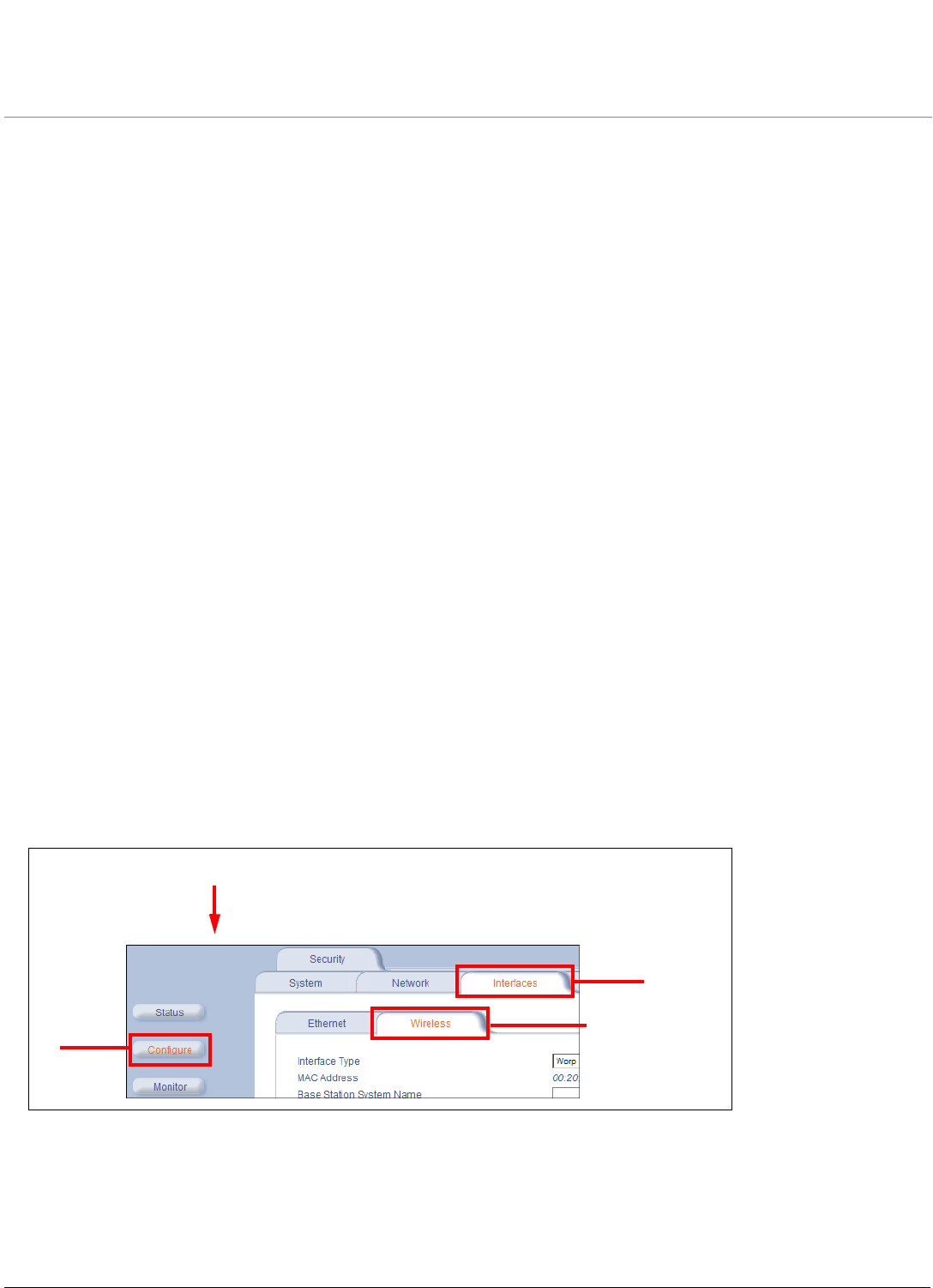
MP.11-R Installation and Management
48
4
Basic Management
This chapter describes basic features and functionality of the unit. In most cases, configuring these basic features is
sufficient. The “Glossary” in the Tsunami MP.11/QB.11 Reference Manual provides a brief explanation of the terms used.
For CLI commands you can use for basic management, see “Command Line Interface” in the Tsunami MP.11/QB.11
Reference Manual.
The following topics are discussed in this chapter:
•Navigation
•Rebooting and Resetting
•General Configuration Settings
•Monitoring Settings
•Security Settings
•Default Settings
•Upgrading the Unit
Navigation
To use the Web Interface for configuration and management, you must access the unit. With ScanTool you can
determine the unit’s current IP address. Then enter http://<ip address> in your Web browser (for example http://
10.0.0.1). See Setting the IP Address with ScanTool for details.
NOTE: If you have your Security Internet Options set to High, you may not be able to access the Web interface
successfully; a high security setting disables JavaScript, which is required for running Proxim’s Web browser
interface. Adding the radio’s IP address as a Trusted site should fix this problem.
The Web Interface consists of Web page buttons and tabs. A tab can also contain sub-tabs. The following figure shows
the convention used to guide you to the correct tab or sub-tab.
The Web Interface also provides online help, which is stored on your computer (see Step 13: Install Documentation and
Software for details).
2
3
1
Click Configure > Interfaces > Wireless:
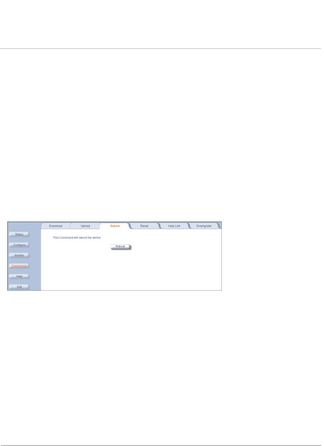
Basic Management MP.11-R Installation and Management
Rebooting and Resetting
49
Rebooting and Resetting
All configuration changes require a restart unless otherwise stated. You can restart the unit with the Reboot command;
see Rebooting, below).
Most changes you make become effective only when the unit is rebooted. A reboot stores configuration information in
non-volatile memory and then restarts the unit with the new values (see Soft Reset to Factory Default).
In some cases, the unit reminds you that a reboot is required for a change to take effect. You need not reboot
immediately; you can reboot after you have made all your changes.
NOTE: Saving of the unit’s configuration occurs only during a controlled reboot or by specifically issuing the CLI Save
command. If you make changes to settings without a controlled reboot (command) and you have not issued the
Save command, a power outage would wipe out all changes since the last reboot. For example, entering static
routes takes effect immediately; however, the routes are not saved until the unit has gone through a controlled
reboot. Proxim strongly recommends saving your settings immediately when you finish making changes.
Rebooting
When you reboot, the changes you have made become effective and the unit is restarted. The changes are saved
automatically in non-volatile memory before the actual reboot takes place.
To reboot, click Commands > Reboot > Reboot. The unit restarts the embedded software. During reboot, you are
redirected to a page showing a countdown timer, and you are redirected to the Status page after the timer counts down
to 0 (zero). The CLI is disconnected during reboot. This means that a new telnet session must be started.
Resetting Hardware
If the unit does not respond for some reason and you are not able to reboot, you can restart by means of a hardware
reset. This restarts the hardware and embedded software. The last saved configuration is used. Any changes that you
have made since then are lost.
To reset the hardware, unplug the unit’s power supply and then reconnect power to the unit.
Soft Reset to Factory Default
If necessary, you can reset the unit to the factory default settings. This should be done only when you are experiencing
problems. Resetting to the default settings requires you to reconfigure the unit.
To reset to factory default settings:
1. Click Commands > Reset.
2. Click the Reset to Factory Default button. The device configuration parameter values are reset to their factory default
values.
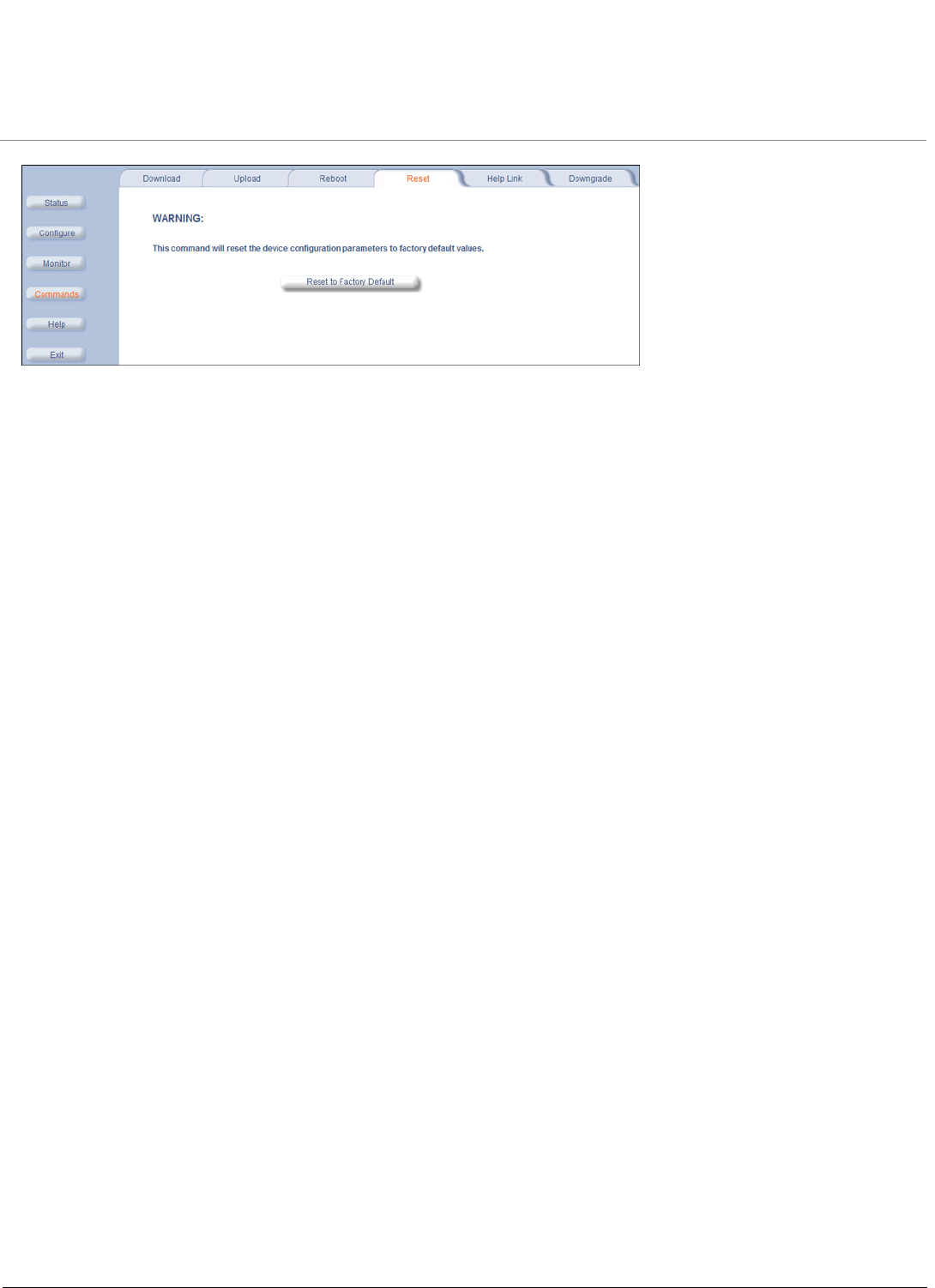
Basic Management MP.11-R Installation and Management
Rebooting and Resetting
50
If you do not have access to the unit, you can use the procedure described in Hard Reset to Factory Default as an
alternative.

Basic Management MP.11-R Installation and Management
General Configuration Settings
51
General Configuration Settings
•System Status: The Status tab showing the system status is displayed automatically when you log into the Web
interface. It is also the default window displayed when you click the Status button on the left side of the window. See
System Status.
•System Configuration: The System Configuration window lets you change the unit’s country, system name, location
name, and so on (see the window to the right). The Country selection is required to enable the correct radio
parameters. The other details help distinguish this unit from other routers, and let you know whom to contact in case
of problems. See System Parameters for more information.
•IP Configuration: The IP Configuration window lets you change the unit’s IP parameters. These settings differ
between Routing and Bridge mode. See Network Parameters for more information.
•Interface Configuration: The Interface configuration pages let you change the Ethernet and Wireless parameters.
The Wireless tab is displayed by default when you click the Interfaces tab.
–Ethernet: To configure the Ethernet interface, click Configure > Interfaces > Ethernet. You can set the
Configuration parameter from this tab for the type of Ethernet transmission. The recommended setting is
auto-speed auto-duplex. See Interface Parameters for more information.
–Wireless: To configure the wireless interface, click Configure > Interfaces > Wireless. For BSUs, the wireless
interface can be placed in either WORP Base or WORP Satellite mode (selected from the Interface Type drop-
down box). SUs can be placed only in WORP Satellite mode. (See Interface Parameters for more information.)
•VLAN Configuration: To configure BSU VLAN parameters, click the Configure button followed by the VLAN tab; the
BSU Table tab is displayed. Click the SUs’ Table tab to configure SU VLAN parameters. Virtual LAN (VLAN)
implementation in the Tsunami MP.11 products lets the BSU and SU be used in a VLAN-aware network and processes
IEEE 802.1Q VLAN-tagged packets. Network resources behind the BSU and SU can be assigned to logical groups.
See VLAN Parameters (BSU Only; Bridge Mode Only) for more information.

Basic Management MP.11-R Installation and Management
Monitoring Settings
52
Monitoring Settings
The unit offers various facilities to monitor its operation and interfaces. Only the most significant monitoring categories
are mentioned here.
•Wireless: To monitor the wireless interfaces, click Monitor > Wireless. This tab lets you monitor the general
performance of the radio and the performance of the WORP Base or WORP Satellite interfaces.
•Interfaces: To monitor transmission details, click Monitor > Interfaces. The Interfaces tab provides detailed
information about the MAC-layer performance of the wireless network and Ethernet interfaces.
•Per Station: Click Monitor > Per Station to view Station Statistics. On the SU, the Per Station page shows
statistics of the BSU to which the SU is registered. On the BSU, it shows statistics of all the SU’s connected to the
BSU. The page’s statistics refresh every 4 seconds.

Basic Management MP.11-R Installation and Management
Security Settings
53
Security Settings
To prevent misuse, the units provide wireless data encryption and password-protected access. Be sure to set the
encryption parameters and change the default passwords.
In addition to Wired Equivalent Privacy (WEP), the units support Advanced Encryption Standard (AES) 128-bit
encryption. Two types of the AES encryption are available. Previous releases supported only the AEC-OCB; the AES
CCM protocol is now also supported.
Proxim highly recommends you change the Network Name, Encryption Key, and Shared Secret as soon as possible.
To do so, click Configure > Interfaces > Wireless. The encryption key is set using the Security tab. For systems that
will use roaming features, the Network Name, Encryption Key, and the Shared Secret should each be the same for all
SUs that are allowed to roam as well as for all BSUs to which these SUs are allowed to roam.
Encryption
You can protect the wireless data link by using encryption. Encryption keys can be 5 (64-bit), 13 (WEP 128-bit), or 16
(AES 128-bit) characters in length. Both ends of the wireless data link must use the same parameter values. In addition to
Wired Equivalent Privacy (WEP), the unit supports Advanced Encryption Standard (AES) 128-bit encryption.
To set the encryption parameters, click Configure > Security > Encryption. See Encryption.
Passwords
Access to the units are protected with passwords. The default password is public. For better security it is recommended
to change the default passwords to a value (6-32 characters) known only to you.
To change the unit’s HTTP, Telnet, or SNMP passwords, click Configure > Management > Password. See Passwords.

Basic Management MP.11-R Installation and Management
Default Settings
54
Default Settings
Feature Model
5054-R 2454-R 4954-R
System Name Tsunami MP.11 5054-R Tsunami MP.11 2454-R Tsunami MP.11 4954-R
Mode of Operation Bridge Bridge Bridge
Routing Disabled Disabled Disabled
IP Address Assignment Type Static Static Static
IP Address 10.0.0.1 10.0.0.1 10.0.0.1
Subnet Mask 255.255.255.0 255.255.255.0 255.255.255.0
Default Router IP Address 10.0.0.1 10.0.0.1 10.0.0.1
Default TTL 64 64 64
RIPv2 Enabled when in Routing
Mode
Enabled when in Routing
Mode
Enabled when in Routing
Mode
Base Station System Name <blank> <blank> <blank>
Network Name OR_WORP OR_WORP OR_WORP
Frequency Channel Channel 149, Frequency
5.745 GHz (FCC Only
devices)
DFS Enabled (World
Mode devices)
Channel 10 (2.412 –
2.462 GHz)
Channel 20, Frequency
4.900 GHz (FCC Only
devices)
Transmit Power Control 0 dB 0 dB 0 dB
Data Rate 36 Mbps 36 Mbps 36 Mbps
Registration Timeout 555
Network Secret public public public
Turbo Mode Disabled Not applicable Not applicable
Channel Bandwidth 20 MHz 20 MHz 20 MHz
Input bandwidth limit
(in Kbps)
36032 36032 36032
Output bandwidth limit
(in Kbps)
36032 36032 36032
Ethernet Configuration Auto-Speed Auto-Duplex Auto-Speed Auto-Duplex Auto-Speed Auto-Duplex
Serial port Baud Rate 9600 9600 9600
SNMP Management Interface Enabled Enabled Enabled
Telnet Management Interface Enabled Enabled Enabled
HTTP Management Interface Enabled Enabled Enabled
HTTP Port 80 80 80
Telnet Port 23 23 23
Telnet Login Timeout 30 30 30
Telnet Session Timeout 900 900 900
Password public public public
Maximum Satellites (per BSU) 250 250 250
MAC Authentication Disabled Disabled Disabled
Radius Authentication Disabled Disabled Disabled
Encryption Disabled Disabled Disabled
Static MAC Address Filter Disabled / No Entries Disabled / No Entries Disabled / No Entries
Ethernet Protocol Filtering All Filters Disabled All Filters Disabled All Filters Disabled

Basic Management MP.11-R Installation and Management
Default Settings
55
DFS Priority Frequency Channel Disabled N/A N/A
Announcement Period (when
roaming enabled)
100 ms 100 ms 100 ms
Multi-Frame Bursting Enabled Enabled Enabled
Storm Threshold Broadcast/Multicast
Unlimited
Broadcast/Multicast
Unlimited
Broadcast/Multicast
Unlimited
Broadcast Protocol Filtering All Protocols Allowed All Protocols Allowed All Protocols Allowed
Dynamic Data Rate Selection Disabled Disabled Disabled
Roaming Disabled Disabled Disabled
NAT Disabled Disabled Disabled
Intra-Cell Blocking Disabled Disabled Disabled
Antenna Alignment Disabled Disabled Disabled
Country Selection US-only device – US
World device – GB
US-only device – US
World device – GB
United States (Public
Safety)
DHCP Server Disabled Disabled Disabled
DHCP Relay Disabled Disabled Disabled
Spanning Tree Protocol Disabled Disabled Disabled
Antenna Gain (For DFS
Threshold compensation)
0 0 Not applicable
Satellite Density Large Large Large
Temperature Logging Enabled Enabled Enabled
Temperature Logging Interval 60 minutes 60 minutes 60 minutes
VLAN Mode BSU: Transparent Mode
SU: Transparent mode when BSU in transparent mode; Trunk mode when BSU
in Trunk mode
Access VLAN ID BSU: N/A; SU: 1
Access VLAN Priority BSU: N/A; SU: 0
Management VLAN ID BSU: -1; SU: -1
Management VLAN Priority BSU: 0; SU: 0
VLAN ID in Trunk VLAN Table BSU: N/A; SU: 1
Feature Model
5054-R 2454-R 4954-R

Basic Management MP.11-R Installation and Management
Upgrading the Unit
56
Upgrading the Unit
The units are equipped with embedded software that can be updated when new versions are released. Updating the
embedded software is described in Web Interface Image File Download. A TFTP server is provided on the
Documentation and Software CD; the server is required to transfer the downloaded file to the unit. See TFTP Server
Setup.
To access all resolved problems in our solution database, or to search by product, category, keywords, or phrases, go to
http://support.proxim.com. You can also find links to drivers, documentation, and downloads at this link.
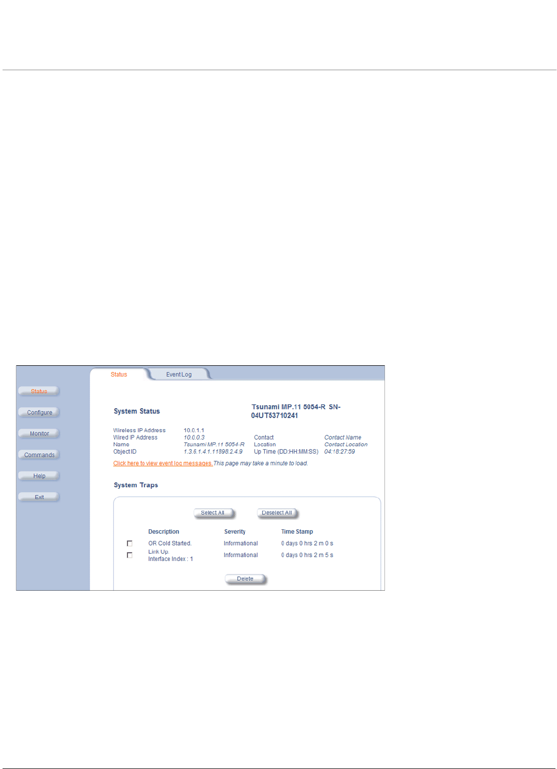
MP.11-R Installation and Management
57
5
System Status
This chapter describes viewing system status and event log information from the unit’s Web Interface.
Click on the Status button to access system and event log information. See the following sections:
•Status
•Event Log
Help and Exit buttons also appear on each page of the Web interface; click the Help button to access online help; click
the Exit button to exit the application.
For an introduction to the basics of management, see Basic Management.
Status
The Status tab showing the system status is displayed automatically when you log into the Web Interface. It also is the
default window displayed when you click the Status button on the left side of the window.
The Status tab shows the System Status and the System Traps.
System Status
The basic system status is shown in this section, including the version number of the embedded software.
Systems Traps
The status of system traps is shown in this section. System traps occur when the unit encounters irregularities. Deleting
system traps has no effect on the operation of the unit. System traps also are sent to an SNMP manager station (if so
configured). See “Alarm Traps” in the Tsunami MP.11/QB.11 Reference Manual for a list and description of the traps.
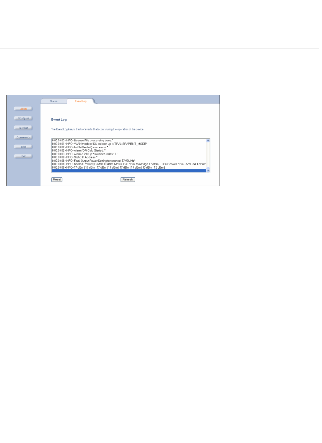
System Status MP.11-R Installation and Management
Event Log
58
Event Log
Click Status > Event Log to view the contents of your Event Log. The Event Log keeps track of events that occur during
the operation of the unit. The Event Log displays messages that may not be captured by System Traps, such as the
Transmit Power for the Frequency Channel selected.
See “Event Log Error Messages” in the Tsunami MP.11/QB.11 Reference Manual for an explanation of messages that
can appear in the Event Log.