Proxim Wireless MP11R-ABG MP.11x Outdoor Wireless Ethernet System User Manual Part I
Proxim Wireless Corporation MP.11x Outdoor Wireless Ethernet System Users Manual Part I
Contents
Users Manual Part I

Part Number 68568r1
Tsunami MP.11 and MP.11a
Version 2.1
Installation and Management
Outdoor: BSU Indoor Outdoor: SU

Notices 2
COPYRIGHT
©2004 Proxim Corporation, Sunnyvale, CA. All rights reserved. Covered by one or more of the following U.S.
patents: 5,231,634; 5,875,179; 6,006,090; 5,809,060; 6,075,812; 5,077,753. This manual and the software
described herein are copyrighted with all rights reserved. No part of this publication may be reproduced,
transmitted, transcribed, stored in a retrieval system, or translated into any language in any form by any means
without the written permission of Proxim Corporation.
TRADEMARKS
Tsunami, Proxim, and the Proxim logo are trademarks of Proxim Corporation. All other trademarks mentioned
herein are the property of their respective owners.
FCC COMPLIANCE
This document provides regulatory information for the following wireless outdoor products:
• Tsunami MP.11 2411 BSU, Tsunami MP.11 2411 SU, Tsunami MP.11 2411 RSU
• Tsunami 2411 QuickBridge 11
• Tsunami MP.11a BSU, Tsunami MP.11a SU, Tsunami MP.11a RSU
• Tsunami MP.11/a Ruggedized BSU, Tsunami MP.11/a Ruggedized SU
This device complies with Part 15 of the FCC Rules. Operation is subject to the following two conditions:
(1) This device may not cause harmful interference
(2) This device must accept any interference received, including interference that may cause undesired
operation.
This device must be professionally installed.
Changes or modifications not expressly approved by Proxim Corporation could void the your authority to operate
the equipment.
This equipment has been tested and found to comply with the limits for a Class B digital device, pursuant to Part
15 of the FCC Rules. These limits are designed to provide reasonable protection against harmful interference in a
residential installation.
This equipment generates, uses, and can radiate radio frequency energy and, if not installed and used in
accordance with the instructions, may cause harmful interference to radio communications. However, there is no
guarantee that interference will not occur in a particular installation. If this equipment does cause harmful
interference to radio or television reception (which can be determined by turning the equipment off and on), you
are encouraged to attempt to correct the interference by one or more of the following measures:
• Reorient or relocate the receiving antenna.
• Increase the separation between the equipment and receiver.
• Connect the equipment into an outlet on a circuit different from that to which the receiver is connected.
• Consult the dealer or an experienced radio or television technician for help.
This device must be professionally installed. Antennas used for the MP.11a product must be fix-mounted on
permanent structures with a separation distance of at least 1.12 meters from all persons during normal operation.

MP.11 and MP.11a Installation and Management
Contents 3
Contents
Copyright ..............................................................................................................................................................2
Trademarks ..........................................................................................................................................................2
FCC COMPLIANCE .............................................................................................................................................2
CHAPTER 1. OVERVIEW.........................................................................................................................................5
In This Release ....................................................................................................................................................6
Wireless Network Topologies...............................................................................................................................6
Active Ethernet .....................................................................................................................................................7
Identifying Network Topology and Equipment .....................................................................................................8
Finding a Suitable Location..................................................................................................................................8
CHAPTER 2. INSTALLATION..................................................................................................................................9
Installing the Indoor MP.11/a ...............................................................................................................................9
Installing the Outdoor MP.11/a...........................................................................................................................16
Installing Documentation and Software .............................................................................................................21
Aligning the Antenna ..........................................................................................................................................21
CHAPTER 3. MANAGEMENT OVERVIEW............................................................................................................23
MP.11/a IP Address ...........................................................................................................................................23
Web Interface Overview.....................................................................................................................................25
MP.11a Country Options....................................................................................................................................27
Command Line Interface Overview....................................................................................................................29
CHAPTER 4. BASIC MANAGEMENT....................................................................................................................32
Rebooting and Resetting....................................................................................................................................33
General Settings.................................................................................................................................................34
Monitoring Settings ............................................................................................................................................39
Security Settings ................................................................................................................................................41
Upgrading the MP.11/a ......................................................................................................................................42
Downgrading the MP.11/a..................................................................................................................................42
CHAPTER 5. WEB INTERFACE ............................................................................................................................43
Status .................................................................................................................................................................43
Configure............................................................................................................................................................45
Additional Interface Information .........................................................................................................................82
Monitor ...............................................................................................................................................................84
Commands .........................................................................................................................................................91
CHAPTER 6. COMMAND LINE INTERFACE ........................................................................................................94
Boot Loader CLI .................................................................................................................................................94
CLI Terminology .................................................................................................................................................95
Navigation and Special Keys .............................................................................................................................96
Commands .........................................................................................................................................................96
CLI Basic Management Commands ................................................................................................................102
Show and Set Parameters ...............................................................................................................................103
Show and Set Parameter Examples ................................................................................................................114
Tables...............................................................................................................................................................114
Country Code Table .........................................................................................................................................119
CHAPTER 7. PROCEDURES...............................................................................................................................122
TFTP Server Setup ..........................................................................................................................................122
Web Interface Image File Download................................................................................................................123
Configuration Backup.......................................................................................................................................123
Configuration Restore ......................................................................................................................................124
Soft Reset to Factory Default ...........................................................................................................................124
Hard Reset to Factory Default..........................................................................................................................125
Forced Reload..................................................................................................................................................125
Image File Download with the Bootloader .......................................................................................................126
APPENDIX A. SPECIFICATIONS ........................................................................................................................128
MP.11/a Hardware ...........................................................................................................................................128
Ruggedized MP.11/a........................................................................................................................................128
Broadband Subscriber Antenna.......................................................................................................................129

MP.11 and MP.11/a Quick Install Guide
Contents 4
Radio Specifications.........................................................................................................................................130
APPENDIX B. TROUBLESHOOTING..................................................................................................................132
MP.11/a Connectivity Issues............................................................................................................................132
Setup and Configuration Issues .......................................................................................................................134
APPENDIX C. SUPPORT AND CONTACTS .......................................................................................................136
GLOSSARY............................................................................................................................................................137

MP.11 and MP.11a Installation and Management
Chapter 1. Overview 5
Chapter 1. Overview
The Tsunami MP.11 and MP.11a are flexible wireless outdoor routers that let you design solutions for point-to-
point links and point-to-multipoint networks.
The Tsunami MP.11 and MP.11a are product families comprising several products (such as the MP.11 2411 Base
Station and the MP.11 2411 Residential Subscriber Unit).
For simplification:
• All products that are part of the MP.11 Product Family are referred to as MP.11.
• All products that are part of the MP.11a Product Family are referred to as MP.11a.
• MP.11/a is used in this book when referring to both the Tsunami MP.11 and MP.11a product families.
Some of the key features of the MP.11/a are:
• The use of a highly optimized protocol for outdoor situations
• Routing and bridging capability
• Asymmetric bandwidth management
• Management through a Web Interface, a Command Line Interface (CLI), or Simple Network Management
Protocol (SNMP)
• A “ruggedized” version that can be placed outside, close to the antenna, to significantly improve range and
ease of installation
Before installing and using the MP.11/a, Proxim recommends you review the following chapters of this manual:
Chapter 1 “Overview” (this chapter)
Provides an overview of the content of this manual as well as wireless network topologies and combinations
that can be built with the MP.11/a.
Chapter 2 “Installation” on page 9
Provides detailed installation instructions for the MP.11/a.
Chapter 3 “Management Overview” on page 23
Explains how to access the MP.11/a for configuration and maintenance.
Chapter 4 “Basic Management” on page 32
Explains the most common settings used to manage the MP.11/a.
Chapter 5 “Web Interface” on page 43
Depicts the Web Interface in a hierarchical manner, so you can easily find details about each item.
Chapter 6 “Command Line Interface” on page 94
An alternative to the Web Interface. This chapter tells you how to obtain help about commands and how to
handle strings, tables, and so on.
The remaining chapters contain supplementary information you may not need immediately.
If you are already familiar with this type of product, you can use the Quick Install Guide to install the MP.11/a.
MP.11 and MP.11/a Quick Install Guide
Chapter 1. Overview 6
IN THIS RELEASE
• Ruggedized, outdoor version of Tsunami MP.11/a
• Antenna alignment tool with audio support
• Reporting and logging of internal unit temperature
• Transmit Power Control support enhanced:
Tsunami MP.11 Version 2.0 Tsunami MP.11 Version 2.1
Full (-0 dB)
Half (-3 dB)
Quarter (-6 dB)
Eighth (-9 dB)
Minimum (-10 dB)
-0 dB
-3 dB
-6 dB
-9 dB
-12 dB
-15 dB
-18 dB (minimum TPC level)
WIRELESS NETWORK TOPOLOGIES
You can use the MP.11/a to set up the following types of topologies:
• Point-to-Point Link (below)
• Point-to-Multipoint Network (on page 7)
A station is a radio set up as either a Base Station, a Subscriber Unit, or a Residential Subscriber Unit. A Base
station can, depending upon its configuration, connect to one or more Subscriber Units. A Subscriber Unit,
however, can connect only to one Base station. A link between two locations always consists of a Base and a
Subscriber Unit.
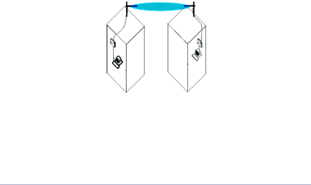
Point-to-Point Link
With a Base and a Subscriber Unit (or a QuickBridge 11 kit), it is easy to set up a wireless point-to-point link as
depicted in the following figure.
A point-to-point link lets you set up a connection between two locations as an alternative to:
• Leased lines in building-to-building connections
• Wired Ethernet backbones between wireless access points in difficult-to-wire environments
Base Station
Unit Subscriber
Unit
MP.11 and MP.11/a Quick Install Guide
Chapter 1. Overview 7
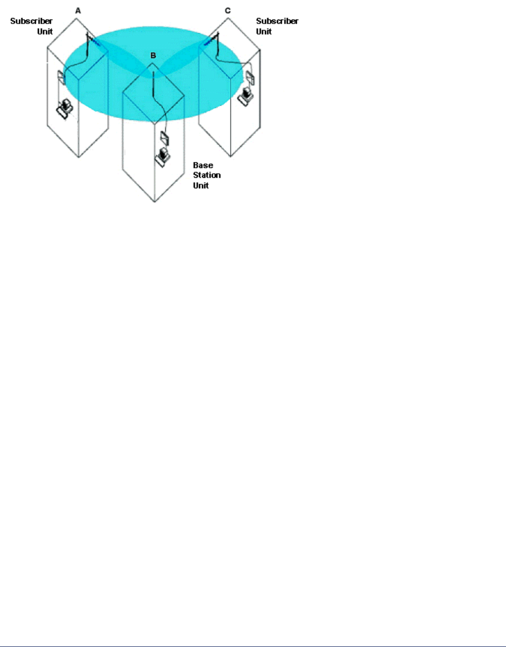
Point-to-Multipoint Network
If you want to connect more than two buildings, you can set up a single point-to-multipoint network with a single
Base station and multiple Subscriber Units, as depicted in the following figure.
Up to 250 Subscriber Units (SUs) can be connected to a Base Station. If a Base Station already has 250 SUs or
RSUs, a new SU cannot be connected to the Base. In this figure, the system is designed as follows:
• The central building B is equipped with a Base Station, connected to either an omni-directional, or a wide
angle antenna.
• The two other buildings A and C are both equipped with a Subscriber Unit connected to a directional antenna.
ACTIVE ETHERNET
The MP.11/a is equipped with an 802.3a/f-compliant Active Ethernet module. Active Ethernet delivers both data
and power to the radio over a single Ethernet cable. If you use Active Ethernet, there is no difference in
operation; the only difference is the power source. The ruggedized (or outdoor) unit has only an Active Ethernet
connection with an integrated power injector.
• The Active Ethernet integrated module receives –48 VDC over a standard Cat 5 Ethernet cable.
• Maximum power supplied to an MP.11 is 11 Watts; maximum power supplied to an MP.11a is 36 Watts.
The units typically draw less than 7.5 Watts.
• For the indoor MP.11/a:
º You must have an Active Ethernet hub (also known as a power injector) connected to the network to use
Active Ethernet,. The Active Ethernet hub is not a repeater and does not amplify the Ethernet data signal.
º The cable length between the Active Ethernet hub and the radio should not exceed 100 meters
(approximately 325 feet).
º If connected to an Active Ethernet hub and an AC power supply simultaneously, the radio draws power
from Active Ethernet.

MP.11 and MP.11/a Quick Install Guide
Chapter 1. Overview 8
IDENTIFYING NETWORK TOPOLOGY AND EQUIPMENT
The MP.11/a can be used in various network topologies and combinations. The required equipment depends
upon the wireless network topology you want to build. Make sure all required equipment is available before
installing the MP.11/a.
The “ruggedized” MP.11/a is designed for outdoor placement. You can connect the MP.11/a to an outdoor
antenna installation with an optional antenna kit. See the appropriate Antenna Installation Guide for details.
WARNING! If you want to connect the MP.11/a to an outdoor antenna system, consult the appropriate
manufacturers’ documentation for additional regulatory information, safety instructions,
and installation requirements.
FINDING A SUITABLE LOCATION
To make optimal use of the MP.11/a, you must find a suitable location for the hardware. The radio range of the
MP.11/a largely depends upon the position of the antenna. Proxim recommends you do a site survey, observing
the following requirements, before mounting the MP.11/a hardware.
• The location must allow easy disconnection of the unit from the power outlet if necessary.
• The unit must not be covered and the air must be able to flow freely around the unit.
• The unit must be kept away from vibration, excessive heat, and humidity, and kept free from dust.
• The installation must conform to local regulations at all times.
Note: The Tsunami MP.11/a Configure System window provides a selectable Country field that
automatically provides the allowed bandwidth and frequencies for the selected country as well as,
where applicable, Dynamic Frequency Selection (DFS) and Transmit Power Control (TPC).
European installers should not add an antenna or an amplifier until the MP.11a Country is selected and
the unit is rebooted. The output power level of the final channel selected by DFS scan can be found
in the Event Log (see “Event Log” on page 44).

MP.11 and MP.11a Installation and Management
Chapter 2. Installation 9
Chapter 2. Installation
This chapter describes the steps required to install and mount the MP.11/a, such as:
• Installing the Indoor MP.11/a below
• Installing the Ruggedized MP.11/a on page 16
• Installing Documentation and Software on page 21
Note: The installation does not cover the mounting and connection of antennas. See the applicable Antenna
Installation Guide (MP.11 or MP.11a).
If you are already familiar with this type of product, you can use the Quick Install Guide for streamlined installation
procedures.
INSTALLING THE INDOOR MP.11/a
The indoor MP.11/a supports two power methods⎯an AC power outlet and Active Ethernet. The power supply
accepts an input AC voltage in the range of 100-240 VAC.
The following installation procedure provides instructions for attaching both the power and Ethernet connectors.
In situations without an external antenna (for example, during a desk tryout), the antenna cable is not required.
WARNING!
For your own safety, use only the power cord supplied with the unit. The metal case of the MP.11/a must
be grounded through the ground connection that is provided on the metal case. The antenna grounding,
the surge arrestor, and the MP.11/a housing must be bonded together and grounded in one location to
avoid ground current loops.
The Indoor MP.11/a Product Package
Each indoor MP.11/a comes with the following:
• One metal base for ceiling or desktop mounting (includes two screws)
• Mounting hardware
º Four 3.5 mm x 40 mm screws
º Four 6 mm x 35 mm plugs
• One power supply
• One Tsunami MP.11/a Installation CD-ROM containing:
º Software Installation Package (starts automatically when CD is inserted in CD-ROM drive; can be started
by double-clicking SETUP.EXE).
º Online Help
º Documentation (Quick Install Guide, Installation and Management manual, Antenna Installation Guides)
º ScanTool (a utility with which you can obtain or set the IP address of the MP.11/a for access; see
“ScanTool” for more information).
º TFTP Server (which lets you transfer files across the network).
Note: All software CD-ROMs that come with your Tsunami products include a readme.txt or readme.html file.
This file contains information about the software version and drivers. You are advised to print and read
the readme file prior to installing your Tsunami products, as it may contain additional information that was
not available when this document was printed.
MP.11 and MP.11/a Quick Install Guide
Chapter 3. Management Overview 10
Indoor Installation Procedure
To install the indoor MP.11/a:
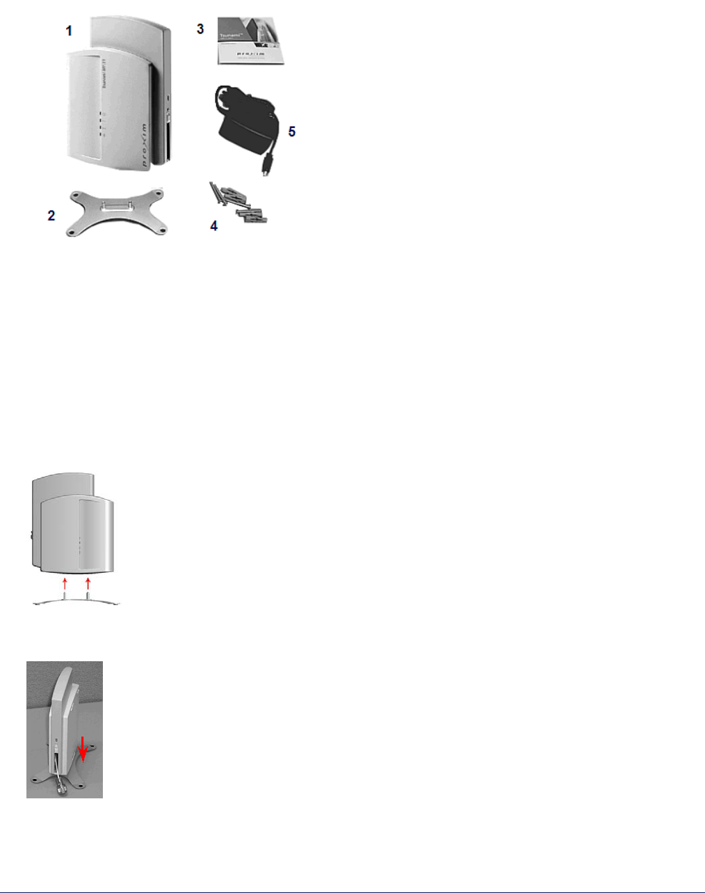
1. Unpack the unit and accessories from the shipping box. The MP.11/a kit contains the following items:
Shown in picture:
1 Tsunami MP.11/a unit
2 Mounting stand
3 Documentation and software CD-ROM
4 Wall mounting hardware
5 Power supply with power cord
The shipment also includes the Tsunami MP.11/a Quick Install Guide.
2. If you intend to install the unit free-standing, or if you intend to mount it to the ceiling, use a Phillips
screwdriver to attach the metal base to the underside of the unit. The metal base and screws are provided
(see “Mounting the Indoor MP.11/a” on page 12 for more information).
3. Unlock the unit’s cable cover. To release the cable cover, press down on the cable cover lock located in the
front center of the unit.
MP.11 and MP.11/a Quick Install Guide
Chapter 3. Management Overview 11
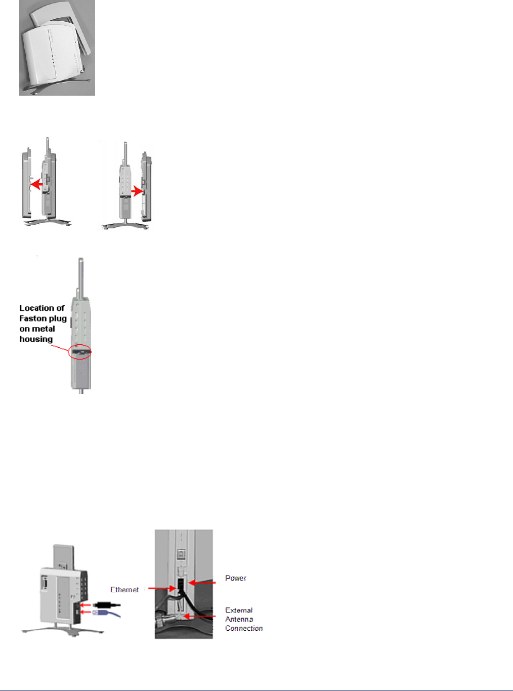
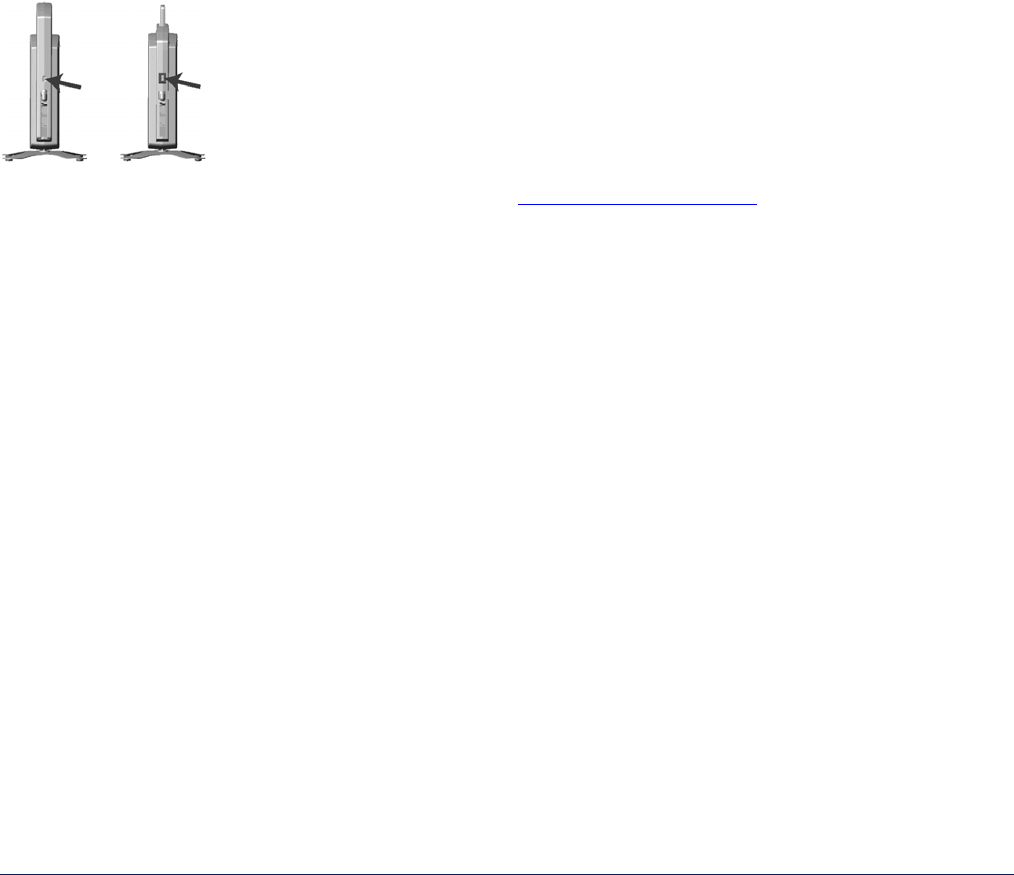
4. Remove the cable cover.
5. Remove the front cover from the unit (the side with the LED indicators, shown in the figure on left); then
remove the back cover (figure on right).
6. Connect the grounding wire to the MP.11/a using the Faston plug on the metal case, next to the power plug.
7. Connect one end of an Ethernet cable (not supplied) to the Ethernet port. The other end of the cable should
not be connected to another device until after installation is complete.
º Use a straight-through Ethernet cable if you intend to connect the MP.11/a to a hub, switch, patch panel,
or Active Ethernet power injector.
º Use a cross-over Ethernet cable if you intend to connect the MP.11/a to a single computer.
8. If you are not using Active Ethernet, or you want to connect the MP.11/a to Active Ethernet and AC power
simultaneously, attach the AC power cable to the MP.11/a’s power port.
To disconnect the power cable, slide back the black plastic fitting and gently pull the cable from the connector.
MP.11 and MP.11/a Quick Install Guide
Chapter 3. Management Overview 12
9. Connect the free end of the Ethernet cable to a hub, switch, patch panel, Active Ethernet power injector, or an
Ethernet port on a computer.
10. If using AC power, connect the power cord to a power source (such as a wall outlet) to turn on the unit.
11. Place the unit in the final installation location (see “Mounting the Indoor MP.11/a” below for details).
12. Replace the back cover, front cover, and cable cover. Be careful to avoid trapping the antenna, power, and
Ethernet cables when replacing the cable cover.
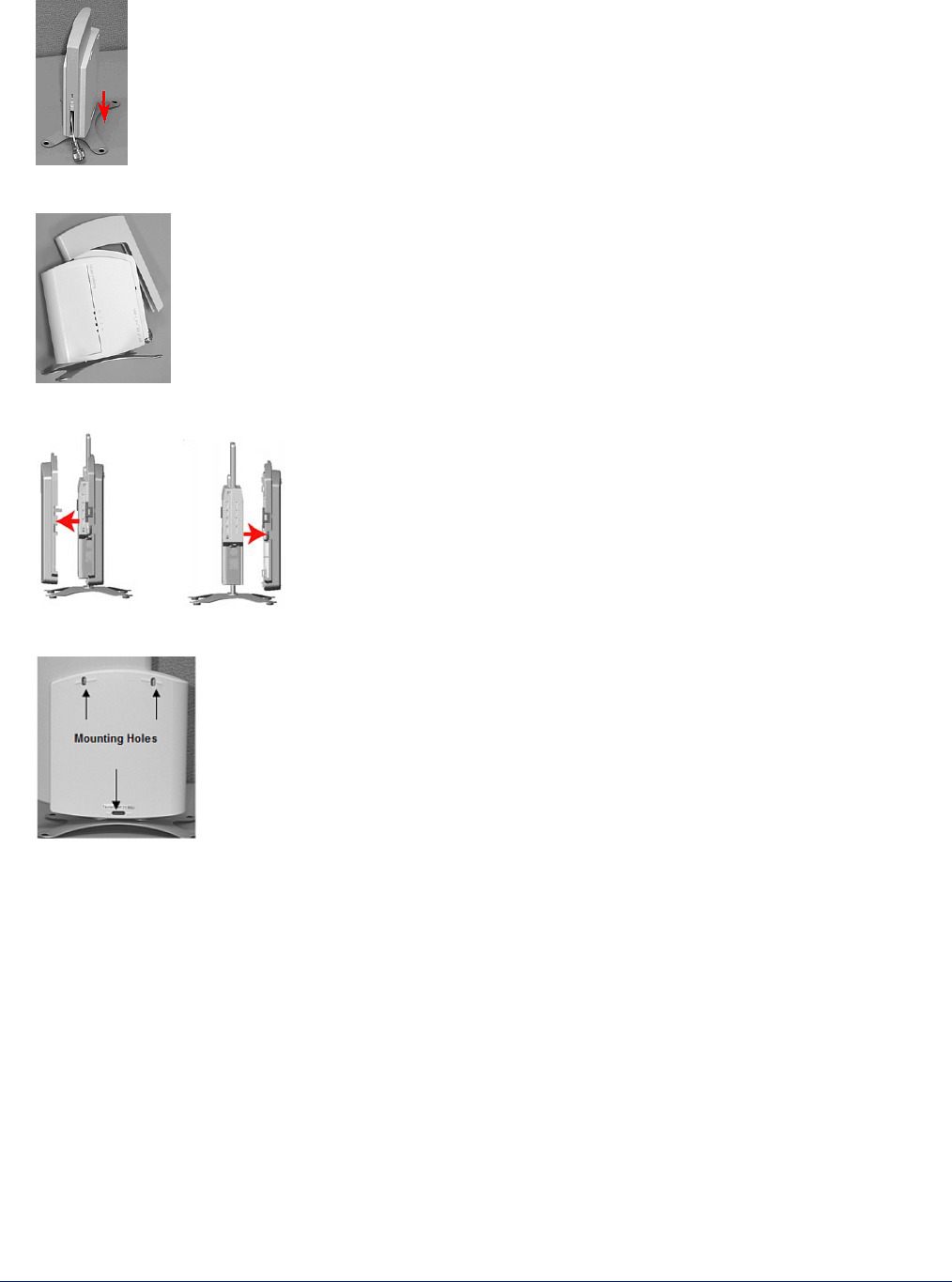
Attaching a Kensington Security Lock (Optional)
If so desired, you can attach a Kensington lock to secure the cable cover into place. This protects the unit from
unauthorized tampering.
The MP.11/a enclosure includes a Kensington Security Slot for use with a Kensington locking mechanism. When
properly installed, a Kensington lock can prevent unauthorized personnel from stealing the MP.11/a. In addition,
the Kensington lock secures the cable cover in place, which prevents tampering with the Ethernet and power
cables.
The Kensington Security Slot is shown in the following figures (the figure on the left shows the slot with the cable
cover attached; the figure on the right shows the slot with the cable cover removed).
For information about Kensington security solutions, go to http://www.kensington.com .
Mounting the Indoor MP.11/a
The following are the mounting options for the MP.11/a:
• Desktop Mount
• Wall Mount
• Ceiling Mount
Desktop Mounting
This procedure consists of attaching the metal base to the MP.11/a unit. See “Indoor Installation Procedure” on
page 10.
Wall Mounting
Follow these steps to mount the MP.11/a on a wall:
1. Identify the location at which you intend to mount the unit.
2. If the MP.11/a’s power supply is plugged in, unplug it,
3. Use a Phillips screwdriver to remove the metal base from the underside of the MP.11/a (if you have not
already done so).
MP.11 and MP.11/a Quick Install Guide
Chapter 3. Management Overview 13
4. Press down on the cable cover lock to release the cable cover .
5. Remove the cable cover from the unit.
6. Remove the front and back covers from the unit.
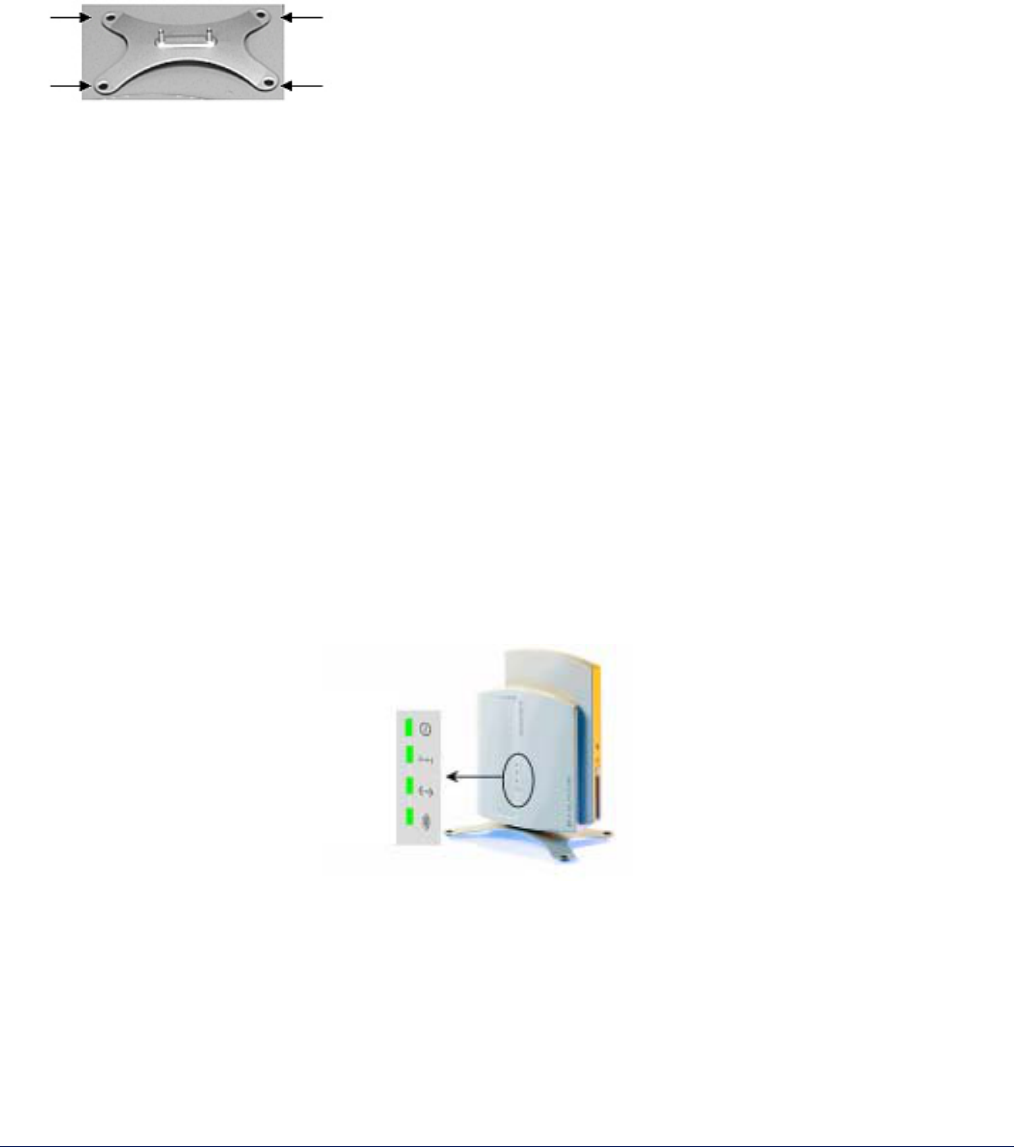
7. Place the back cover on the mounting location and mark the center of the three mounting holes.
8. Remove the cover from the wall and drill a hole at each of the locations you marked. Each hole should be
wide enough to hold a mounting plug (6 mm x 35 mm).
9. Insert a plug into each hole.
(Four 6 mm x 35 mm plugs are provided; you need to use only three of these for wall mounting.)
10. Insert a screw into each of the mounting holes molded into the back cover.
(Four 3.5 mm x 40 mm pan-head screws are provided; you need to use only three of these for wall mounting.)
11. Insert the screws into the wall plugs; use a screwdriver to tighten the screws and attach the back cover to the
wall.
12. Attach Ethernet and power cables to the MP.11/a unit, as necessary.
13. Snap the unit into the back cover, replace the front cover, and replace the cable cover.
14. Turn on the MP.11/a (see “Switching On the Indoor MP.11/a” on page 14).
MP.11 and MP.11/a Quick Install Guide
Chapter 3. Management Overview 14
Ceiling Mounting
Follow these steps to mount the MP.11/a to a ceiling:
1. If the MP.11/a’s power supply is plugged in, unplug it.
2. Use a Phillips screwdriver to attach the metal base to the underside of the MP.11/a, if you have not already
done so. See “Indoor Installation Procedure” on page 10 for an illustration.
3. Feed a mounting screw through each of the four rubber feet. The MP.11/a comes with four 3.5 mm x 40 mm
pan-head screws.
4. Remove the screws from the rubber feet.
5. Turn the MP.11/a upside down and position the base against the ceiling where you want to mount the unit.
6. Mark the center of the four mounting holes in the rubber feet.
7. Set the MP.11/a aside and drill a hole at each of the locations you marked above. Each hole should be wide
enough to hold a mounting plug (6 mm x 35 mm).
8. Insert a plug into each hole. The MP.11/a comes with four 6 mm x 35 mm plugs.
9. Insert the screws into the holes you made previously in the rubber feet.
10. Insert the screws into the mounting plugs. Use a screwdriver to tighten the screws and attach the MP.11/a’s
metal base to the ceiling.
Switching On the Indoor MP.11/a
The MP.11/a can be powered by a power supply (just plug the power cord of the power supply into an AC power
outlet), or by Active Ethernet (connect an Active Ethernet splitter to the Ethernet cabling).
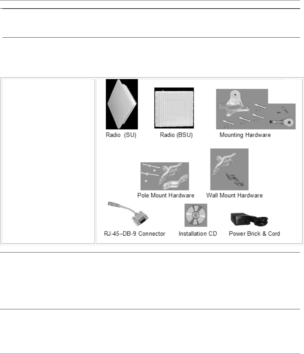
When the power is switched on, the MP.11/a performs startup diagnostics. When startup is completed, the LEDs
show the operational state of the MP.11/a (see the following figure).
The following table shows the status of the LEDs when the MP.11/a is operational (the fourth LED is only
used during Dynamic Frequency Selection on a Base Station; flashing green indicates scanning).
Powe
r
Ethernet Link
Wireless Link

MP.11 and MP.11/a Quick Install Guide
Chapter 3. Management Overview 15
Power
OFF Power is not present or is malfunctioning.
GREEN Power is present; the unit is operational.
AMBER The unit is initializing after reboot (less than two minutes); it cannot get a dynamic IP
address or is in Forced Reload state when Ethernet LED also is amber.*
RED A fatal error in the unit.
Ethernet Link
OFF Not connected.
GREEN Connected at 10 Mbps.
BLINKING GREEN Data is being sent.
AMBER Connected at 100 Mbps, in Forced Reload state when Power LED also is amber*, or
the unit is initializing after reboot (less than two minutes).
BLINKING AMBER Data is being sent.
RED An error in data transfer.
Wireless Link
OFF Wireless interface is up properly but no wireless link established.
GREEN Immediately after connecting a wireless link.
BLINKING GREEN Data is being sent or the wireless interface is initializing after reboot (less
than two minutes).
RED There is a fatal error on the wireless interface.
* See “Forced Reload” on page 125.
Continue with “Installing Documentation and Software” on page 21.
MP.11 and MP.11/a Quick Install Guide
Chapter 3. Management Overview 16
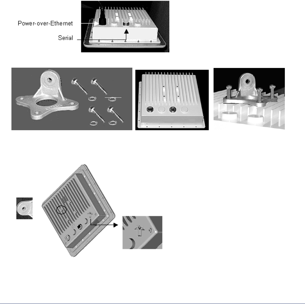
INSTALLING THE OUTDOOR MP.11/a
The outdoor MP.11/a radio contains a state-of-the-art wireless access point, high gain performance flat panel
antenna, and Power-over-Ethernet (the sole means of power for the outdoor MP.11/a). For further protection, the
Power-over-Ethernet connection has a built-in surge arrestor.
The installation procedure on page 17 provides instructions for attaching the Ethernet connector. An antenna
cable is required only when you use an optional external antenna.
WARNING
To ensure proper grounding, use the hole on the back of each radio and the provided grounding screws
to attach a ground wire to each radio. Use proper wire grounding techniques in accordance with your
local electrical codes. You also can mount the radios on tall, multi-section poles with guide wires. For
these types of installations, you should consult professionals with experience.
The Outdoor MP.11/a Product Package
Each outdoor MP.11/a comes with the following, as well as a printed copy of the Tsunami MP.11/a Quick Install
Guide.
1. One MP.11/a Ruggedized
Radio with integrated
antenna (SU) or with an
external antenna connection
(BSU)
2. Mounting hardware to attach
to radio for mounting
3. Hardware for pole mounting
4. Hardware for wall mounting
5. One RJ11 to DB9 connector
for serial connection
6. One Tsunami MP.11/a
Version 2.1 Installation CD
containing:
º Installation Package
º Documentation
º ScanTool
º FTP Server
7. Power Brick and cord
Notes:
• All software CD-ROMs that come with your Tsunami products include a readme.txt or readme.html file. This
file contains information about the software version and drivers. You are advised to print and read the
readme file prior to installing your Tsunami products, as it may contain additional information that was not
available when this document was printed.
• Cables are not provided with the MP.11/a.
MP.11 and MP.11/a Quick Install Guide
Chapter 3. Management Overview 17
Outdoor MP.11/a Installation Procedure
Before mounting the MP.11/a, note the MAC address and the serial number of the unit along with the name of the
site at which the unit was installed. Keep this information in a safe place. The MAC address is required to add
the Subscriber Unit to a Base Station database; the serial number is required to obtain support from Proxim.
The outdoor MP.11/a is designed to directly mount to a pole. Using the supplied brackets and hardware, you can
mount the radio to a 1-1/4 inch to 3-inch pole (outside diameter). Using just one of the pole mounting brackets,
you can mount the radio to a wall or other flat surface.
To install the outdoor MP.11/a:
1. Unpack the unit and accessories from the shipping box.
2. Attach a Cat5e cable (not provided) to the Power-over-Ethernet port on the back of the radio (see the
following figure).
3. Screw mounting piece (A) to the back of the radio unit with screws and washers (B) as shown:
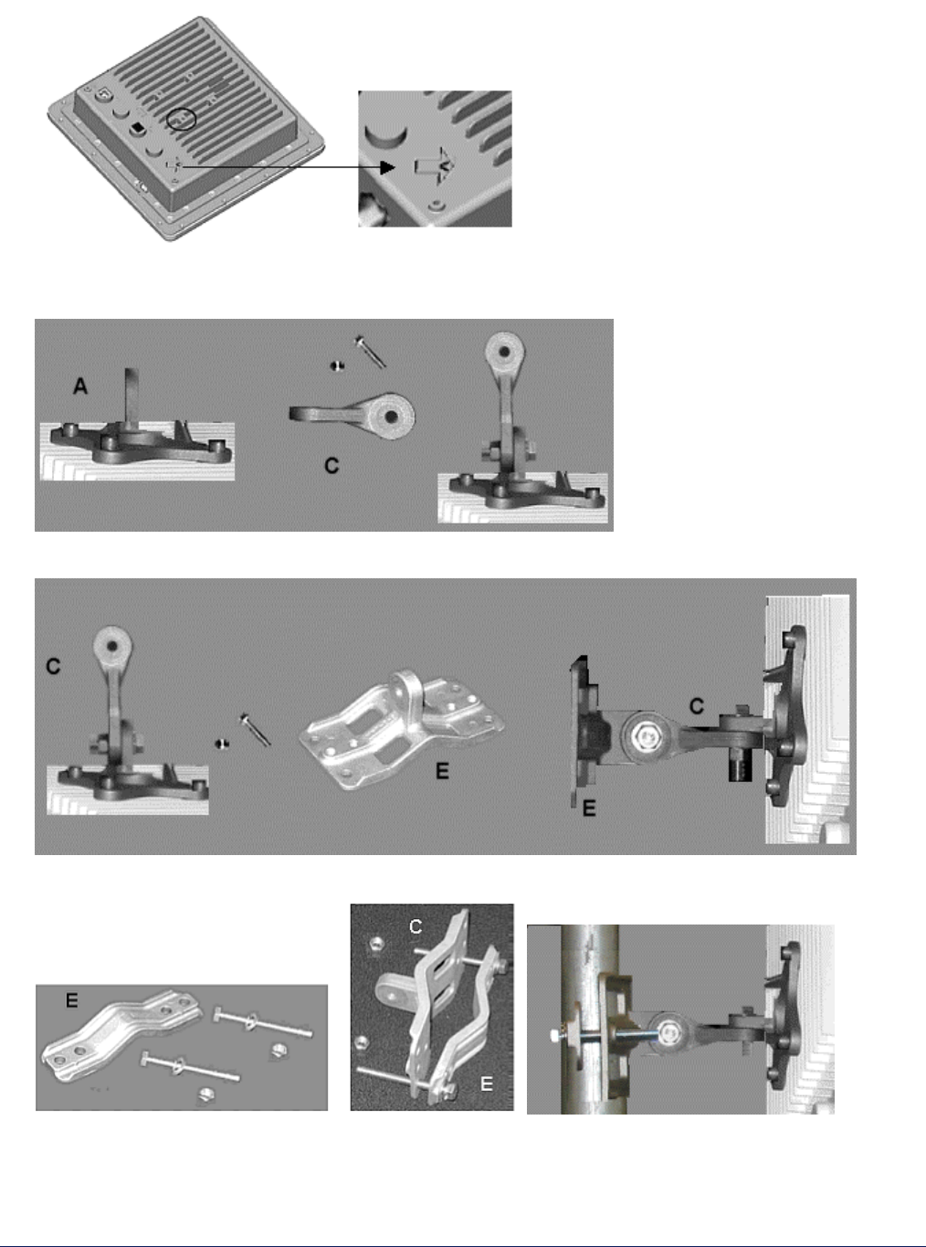
There is an arrow on the back of the radio that indicates the direction to mount for vertical polarization. Mount
the radio with the following portion of the bracket in the position circled in the following figure for vertical
alignment.
A B
MP.11 and MP.11/a Quick Install Guide
Chapter 3. Management Overview 18
For horizontal alignment, mount the radio as shown below:
4. Attach bracket connector (C) to mounting piece (A) with the screw provided, as shown below. This extension
piece gives the radio more possible tilt, letting you more accurately adjust for elevation.
5. Attach bracket connector (C) to bracket (E) with the nut and screw provided.
6. To mount to a pole, insert screws through bracket F and fasten around pole to bracket E and secure.
MP.11 and MP.11/a Quick Install Guide
Chapter 3. Management Overview 19
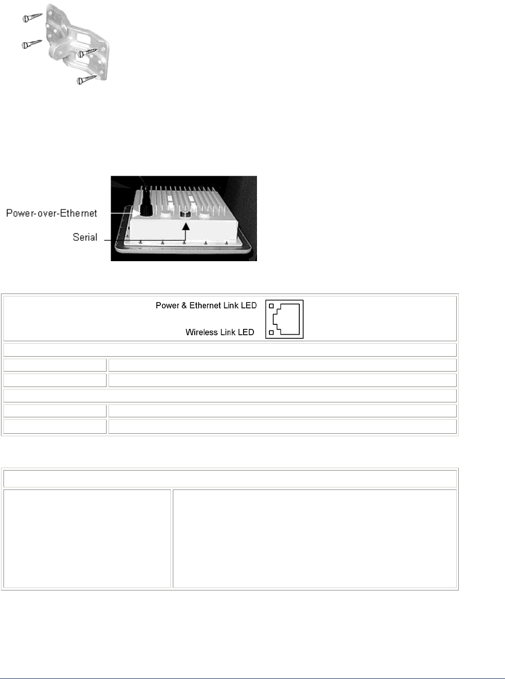
To wall-mount the outdoor MP.11/a, mount bracket (E) to wall using 4 screws provided, as shown:
Switching On the Outdoor MP.11/a
You can power on the outdoor MP.11/a by connecting the Active Ethernet splitter to the Ethernet cabling.
When the power is switched on, the MP.11/a performs startup diagnostics. When startup is complete, the LEDs
show the operational state of the MP.11/a (see the following figure).
LEDs—Power / Ethernet and Wireless Connections
Power & Ethernet Link
GREEN Power is on, the radio is up, and the Ethernet link is also up..
BLINKING GREEN Power is on, the radio is coming up and the Ethernet is down.
RF (Wireless) Link
GREEN A wireless link has been established..
BLINKING GREEN A wireless link is being established..
Recommended Power and Ethernet Cable
Recommended Cable
Function
Type
Impedance
Recommended cables
Maximum Distance
Connector type, radio end
Connector type, power & Ethernet
adapter end
Power (DC) and Ethernet connection
Cat 5e, UV shielded
100 ohms
4 UTP, 24 AWG, UL rated
330 feet / 100 meters
RJ-45 female, weatherized using weatherproof connector
8-pin DIN male connector with solder cup/cover or crimp pins
to power & Ethernet adapter
MP.11 and MP.11/a Quick Install Guide
Chapter 3. Management Overview 20
Serial Connection
The serial connection is made with an RJ-11 to DB-9 connector (also referred to as a “dongle”). Connect the
RJ-11 end to the radio and connect the serial (DB-9) end to your PC to assist you in aligning the antenna and to
issue CLI commands.
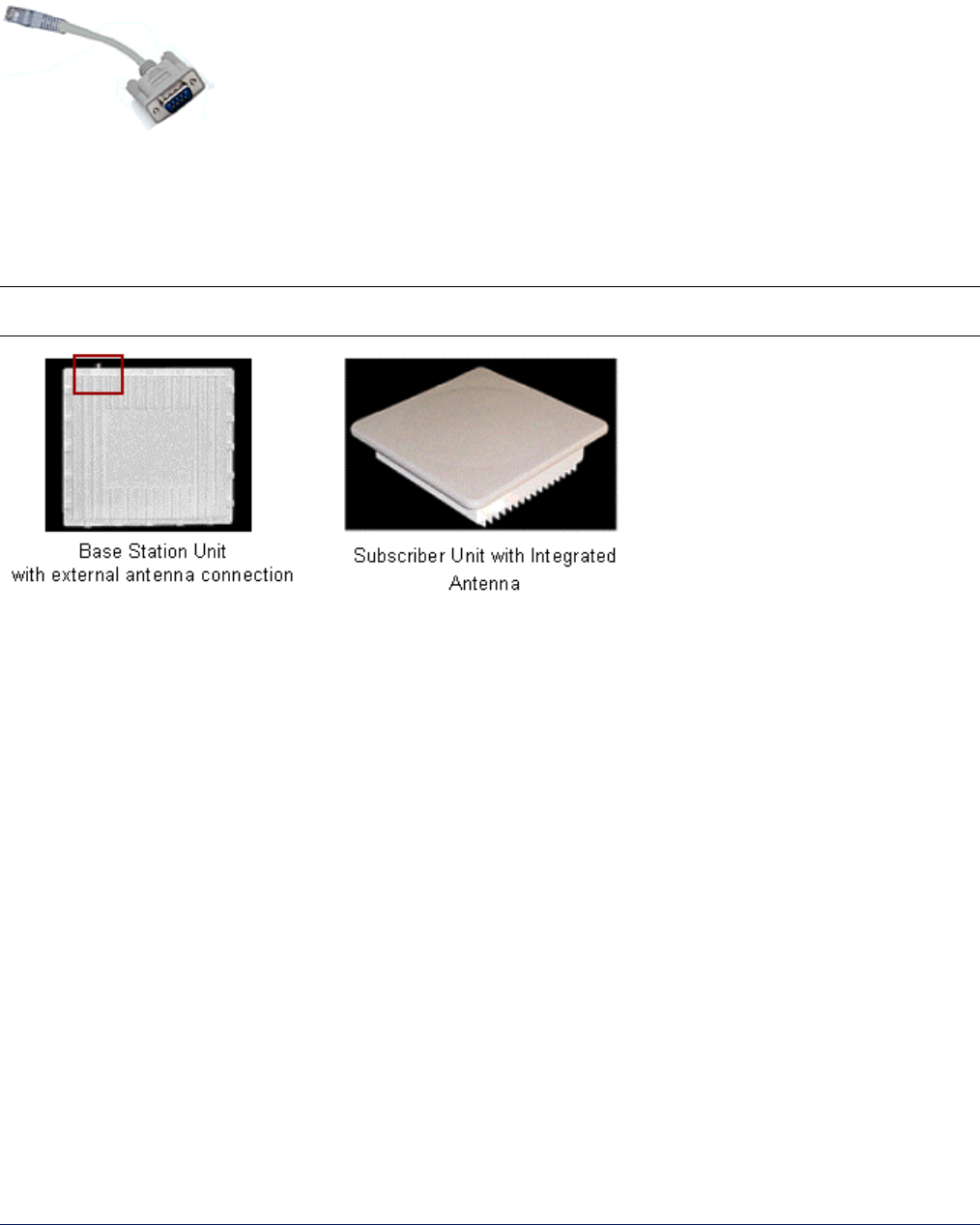
External Antenna Connection
The integrated antenna is supported on Subscriber Units only; the Base Station has an external antenna
connector and no integrated antenna. For more information about external antennas, see the Tsunami MP.11
Antenna Installation Guide and Tsunami MP.11a Antenna Installation Guide.
Note: The window antenna documented in the antenna installation guides does not apply to the outdoor
MP.11/a.
Continue with “Installing Documentation and Software.”

MP.11 and MP.11/a Quick Install Guide
Chapter 3. Management Overview 21
INSTALLING DOCUMENTATION AND SOFTWARE
The MP.11/a also comes with documentation and software on a CD-ROM.
To install the documentation and software on a computer or network:
1. Place the CD-ROM in a CD-ROM drive. The installer normally starts automatically. You can also start the
installer manually by running the setup.exe program in the root directory of the CD-ROM.
2. Click the Install Help and Software button and perform the necessary steps.
The CD-ROM contains the following documentation and software:
Online help
This is the help for the Web Interface. It is stored on your computer or network so it is always available.
Documentation
Documentation also is available in an electronic (PDF) form, including the Tsunami MP.11/a Installation and
Management Guide, Tsunami MP.11/a Antenna Installation Guide, and Tsunami MP.11/a Quick Install Guide.
ScanTool
The ScanTool program is a utility with which you can obtain or set the IP address of the MP.11/a for
management access. See “Setting the IP Address Manually” on page 24 for details.
TFTP Server
The TFTP (Trivial File Transfer Protocol) server lets you transfer files across the network. You can download
configuration and license files, as well as image files for embedded software upgrades, and you can upload
files from the MP.11/a for backup. Here downloading means transferring files to the MP.11/a and uploading
means transferring files in the opposite direction.
ALIGNING THE ANTENNA
Antenna alignment is a process to physically align the antenna of the radio receiver or the transmitter to have the
best possible radio link established between them. The antenna alignment process usually is performed during
installation and after major repairs.
The outdoor MP.11/a has an audible antenna alignment tool that can be activated by plugging in the supplied
serial dongle (supplied with every Base Station) or by issuing the CLI command for antenna alignment. The CLI
command causes both audible and numerical feedback as the CLI shows the running SNR values twice a
second.
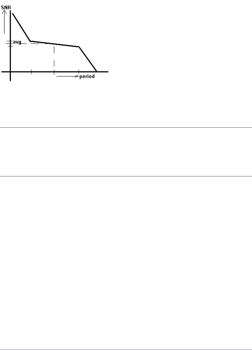
The output from the beeper for antenna alignment consists of short beeps with a variable interval. The interval
changes with the SNR level to assist in correctly aligning the antenna. An increase in signal level is indicated by
a shorter interval between beeps; a reduction in signal level results in beeps further apart.
To allow for precise antenna alignment, small changes in SNR result in large changes in the beep period. The
alignment process averages the SNR, which is represented by an average length beep. When a higher SNR is
received, the beep period is made shorter, dependent upon the difference to the average. A lower SNR results in
a longer period between beeps.
The first five steps are represented by a large change and all following steps are a small change. This acts as if a
magnifying glass is centered around the average SNR and the values next to the average are significantly
different.
MP.11 and MP.11/a Quick Install Guide
Chapter 3. Management Overview 22
When the antenna is aimed, the beep can easily be heard if the SNR is rising (shorter period, higher frequency) or
falling (longer period). When the position of the antenna has been changed, the SNR averaging settles at the
new value and the beeping returns to the average length so the antenna can again be aimed towards rising SNR.
Aiming is complete if moving in any direction results in a falling SNR value, which can be heard as longer periods
between beeps.
Notes:
• Antenna alignment for the Base Station is useful only for a point-to-point link.
• The range of the average SNR must be limited to values from 0 to 48. Anything over 48 is capped at 48.
• AAD is automatically disabled 30 minutes after it is enabled to remove the load of extra messages on the
wireless interface. The default telnet timeout is 900 seconds (15 minutes). If AAD must run for the entire 30
minutes, change the default telnet timeout value greater than 30 minutes (greater than 1800 seconds). This
restriction is for telnet connections only and not for the serial interface. The serial interface never times out.
Antenna Alignment Commands
set aad enable local
Enables display of the local SNR. Local SNR is the SNR measured by the receiver at the near end.
set aad enable remote
Enables display of the remote SNR. Remote SNR is the SNR as measured by the receiver at the far end.
set aad enable average
Enables display of the average SNR. The average SNR is the average of the local and remote SNR.
set aad disable
Disables Antenna Alignment Display (Ctrl-C also disables AAD).

MP.11 and MP.11a Installation and Management
Chapter 2. Installation 23
Chapter 3. Management Overview
This chapter describes how to gain access to the MP.11/a for configuration and management. Three interfaces
are provided for viewing or changing the MP.11/a’s settings:
Web Interface
The Web Interface is a graphical interface based upon Web pages from a built-in Web server.
Command Line Interface
The Command Line Interface (CLI) is a text-based interface using typed commands.
SNMP
You also can use the Simple Network Management Protocol (SNMP) to configure and manage the MP.11/a.
See “SNMP” on page 60 for setup procedures.
Connecting to the MP.11/a requires a direct physical connection with an Ethernet cross-over cable, a serial RS-
232C cable, or a connection through the network.
For the serial connection, you can use only the CLI to configure and manage the MP.11/a. The other connections
allow the use of the Web Interface, SNMP, and the CLI. These other connections require the IP address of the
MP.11/a before you can use the Web Interface, SNMP, or the CLI. See “MP.11/a IP Address” below for more
information.
You can also manage the MP.11/a without an IP address by accessing the MP.11/a through the serial port with a
terminal program such as HyperTerminal (see “HyperTerminal Connection Properties” on page 31).
MP.11/a IP ADDRESS
Because each network is different, an IP address suitable for your network must be assigned to the MP.11/a. You
must have the IP address of the MP.11/a to configure and manage it through its Web Interface, SNMP, or the CLI.
You can manage other basic parameters can be managed as well. ScanTool is included on the documentation
and software CD-ROM to assist you in determining and changing the MP.11/a’s IP address.
The MP.11/a can use either a static or dynamic IP address.
Static IP address
The MP.11/a uses the IP address you have set manually.
Dynamic IP address
The MP.11/a receives its IP address from a DHCP server when it is switched on or rebooted.
The MP.11/a either obtains its IP address automatically through DHCP or it must be set manually. With
ScanTool, you can find out the current IP address of the MP.11/a and, if necessary, change it so that is
appropriate for your network. The MP.11/a is shipped with the static IP address 10.0.0.1 configured.
MP.11 and MP.11/a Quick Install Guide
Chapter 3. Management Overview 24
Setting the IP Address
If you want to set the IP address:
1. Run ScanTool on a computer connected to the same LAN subnet as the MP.11/a, or directly connected to the
MP.11/a with a cross-over Ethernet cable.
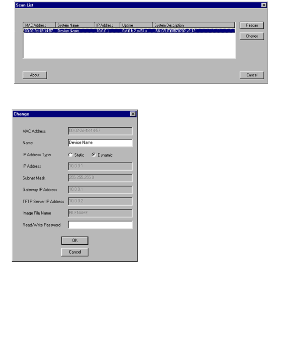
ScanTool scans the subnet for MP.11/a units and displays the units it finds in the main window. The following
figure shows an example of the main window. If necessary, click Rescan to re-scan the subnet and update
the display.
2. Select the MP.11/a for which you want to set the IP address and click Change. The Change dialog window
is displayed, as shown in the following window.
3. To set the IP address manually, ensure that Static is selected as the IP Address Type and fill in the IP
Address and Subnet Mask suitable for the LAN subnet to which the MP.11/a is connected.
To set the IP address dynamically, ensure that Dynamic is selected as the IP Address Type and fill In the
IP Address and Subnet Mask suitable for the LAN subnet to which the MP.11/a is connected.
4. Enter the Read/Write Password (the default value is public) and click OK to confirm your changes. The
respective MP.11/a reboots to make the changes effective.
MP.11 and MP.11/a Quick Install Guide
Chapter 3. Management Overview 25
Note: The asterisks displayed when you enter the password are a set number that does not necessarily equal
the number of characters in the actual password string. This is intended for added security.
WEB INTERFACE OVERVIEW
The Web Interface provides a graphical user interface through which you can easily configure and manage the
MP.11/a. This section describes only how to access the Web Interface; the Web Interface itself described in
“Chapter 4. Basic Management” on page 32 and “Chapter 5. Web Interface” on page 43.
To use the Web Interface, you need only the IP address of the MP.11/a. (See “MP.11/a IP Address” on page 23
for details.)
Note: If the connection is slow or you are not able to connect, use the Internet Explorer Tools option to ensure
you are not using a proxy server for the connection with your Web browser.
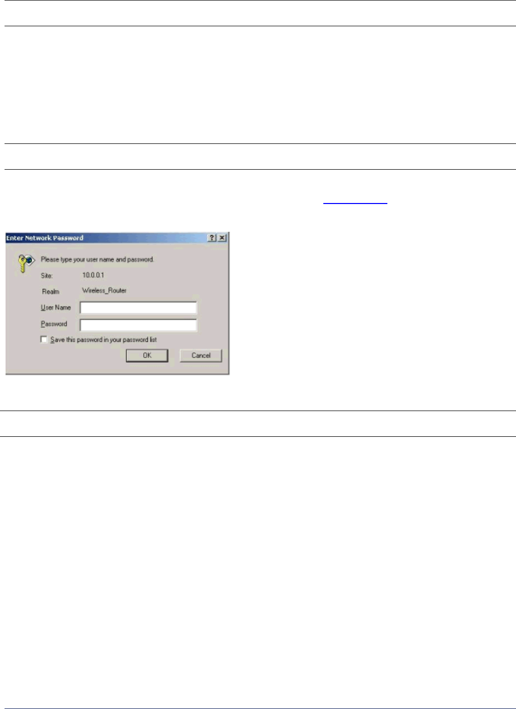
To access the MP.11/a with a Web browser, start your Web browser and enter the IP address of the MP.11/a.
The Web address should appear as http://<ip address> (for example, http://10.0.0.1). A window such as the
following is displayed.
Do not fill in the User Name, enter only the password and click OK. The default password is public.
Note: The asterisks displayed when you enter the password are a set number that does not necessarily equal
the number of characters in the actual password string, which is intended for added security.
The System Status window of the Web Interface is displayed.
MP.11 and MP.11/a Quick Install Guide
Chapter 3. Management Overview 26
You now have access to the MP.11/a Web Interface.
To view or change basic system information, click the Configure button on the left side of the Web interface
window, then click the System tab.

MP.11 and MP.11/a Quick Install Guide
Chapter 3. Management Overview 27
MP.11a COUNTRY OPTIONS
Selecting a Country
The Tsunami MP.11/a Configure System window provides a selectable Country field that automatically provides
the allowed bandwidth and frequencies for the selected country as well as, where applicable, Dynamic Frequency
Selection (DFS) and Transmit Power Control (TPC).
MP.11/a kits sold in the United States are pre-configured to scan and display only the outdoor frequencies
permitted by the FCC. No other Country selections, channels, or frequencies may be configured. MP.11/a kits
sold outside of the United States and Canada support the selection of a Country by the professional installer.
Click the Configure button and the System tab; then select the appropriate country for your regulatory domain
from the Country drop-down box.
Continue configuring settings as desired; then click the Commands button and the Reboot tab to save and
activate the settings. Alternatively, if you want to save the configuration settings to the flash memory but not
activate the settings, use the save config CLI command.
The Dynamic Frequency Selection (DFS) and Transmit Power Control (TPC) features are enabled automatically
when you choose a country with a regulatory domain that requires them. The Country selection pre-selects and
displays only the allowed frequencies for the selected country.
Dynamic Frequency Selection
A country selection with DFS enabled causes the MP.11a Base Station to come up in scan mode. It scans the
available frequencies and channels to avoid radar and select a channel with the strongest signal.
Note: Scanning is performed only on the frequencies allowed in the regulatory domain of the country selected,
when it is required for radar detection and avoidance.
The MP.11a Subscriber Unit also comes up in scan mode to scan all available frequencies to find a Base Station
with which it can register. Scanning may take several minutes. Scanning is indicated by a flashing green LED
(the fourth LED in the case of the Base Station; the Wireless LED for an SU). When the link is established, the
fourth LED on the BSU goes off. The third LED on the SU continues flashing until it establishes a WORP link.
After establishing a WORP link, the LED stops flashing and continues to glow green.
See “Dynamic Frequency Selection” on page 82 for more information.
Transmit Power Control
Transmit Power is a manual configuration selection to reduce the output power in the radio. The output power
level for the operating frequency can be found in the Event Log of the MP.11a embedded software.
By default, the Tsunami MP.11a lets you transmit at the maximum output power for the country or regulatory
domain and frequency selected. However, with Transmit Power Control (TPC), you can adjust the output power
of the unit to a lower level in order to reduce interference from neighboring devices or to use a higher gain
antenna without violating the maximum radiated output power allowed for your country. Also, most countries in
the ETSI regulatory domain require the transmit power to be set to a 6 dB lower value than the maximum allowed
EIRP when link quality permits. You can see your radio’s current output power for the selected frequency in the
event log.

MP.11 and MP.11/a Quick Install Guide
Chapter 3. Management Overview 28
The event log shows the selected power for all data rates, so you must look up the relevant data rate to determine
the actual power level. For example, the event log shows:
0 00:00:08–INFO- Final Power 6 Mb 20 dBm, MaxRD 30 dBm, MaxEdge 31 dBm, -TPC Scale 0 dBm – Ant Red 0 dBm*
0 00:00:09–INFO- 20 dBm | 20 dBm | 20 dBm | 20 dBm | 20dBm | 19 dBm
This shows that the output power is set at 20 dBm for the data rate 6, 9, 12, 18, or 24 Mbps or at 19 dBm when
the selected data rate is 36 Mbps. The first line shows that 6 Mbps is selected, so the transmit power is 20 dBm.
Note: This feature only lets you decrease your output power; it does not let you increase your output power
beyond the maximum allowed defaults for your frequency and country.
See “Configure: 1) System” on page 45 to configure Country, Dynamic Frequency Selection, and Transmit
Power Control.
MP.11 and MP.11/a Quick Install Guide
Chapter 3. Management Overview 29
COMMAND LINE INTERFACE OVERVIEW
The Command Line Interface (CLI) is a text-based interface with which you can configure and manage the
MP.11/a by entering commands. This section describes only how to access the CLI; the interface itself is
described in “Chapter 6. Command Line Interface” on page 94.
The CLI can be used as an alternative to the Web Interface. You can, for example, quickly change the settings of
the MP.11/a by running commands in a batch.
The CLI is accessible through the:
• Ethernet port connected through the network or with a cross-over Ethernet cable between the computer and
the MP.11/a
• Serial port of the MP.11/a
Ethernet Port
To use the CLI through the Ethernet port, you must have a telnet program and the IP address of the MP.11/a. On
most computers, the telnet program is called telnet. See “MP.11/a IP Address” on page 23 for details.
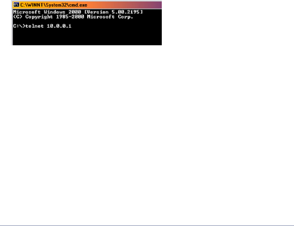
To access the MP.11/a through Ethernet:
1. From the Windows Start menu, select Run; enter cmd and click OK.
2. Enter telnet followed by the IP address, as shown in the following sample DOS command window.
3. You are prompted for your password:
Please enter password:
4. Enter the password (the default password is public).
You can now use the CLI.

MP.11 and MP.11/a Quick Install Guide
Chapter 3. Management Overview 30
Serial Port
You can also use the CLI through the serial port of the MP.11/a with a terminal program such as HyperTerminal.
You can use this method for cases in which other access methods cannot be used, or when the IP address of the
MP.11/a cannot be set or retrieved. Also see “Hard Reset to Factory Default” on page 125.
To use the CLI through the serial port of the MP.11/a the following items are required:
• A serial cable with a male and a female DB-9 connector. The serial cable must have a minimum of the
following connections:
Male Connector Female Connector
Pin 2 ----------------Æ Pin 2
Pin 3 ----------------Æ Pin 3
Pin 5 ----------------Æ Pin 5
• An ASCII terminal program, such as HyperTerminal.
Proxim recommends you switch off the MP.11/a and the computer before connecting or disconnecting the serial
cable.
Note: For the outdoor MP.11/a, you can connect to the serial port by connecting the included RJ-11 to DB-9
connector from the radio (RJ-11 connection) to your computer’s serial port (DB-9 connection).
To access the MP.11/a through the serial port:
1. Start your terminal program.
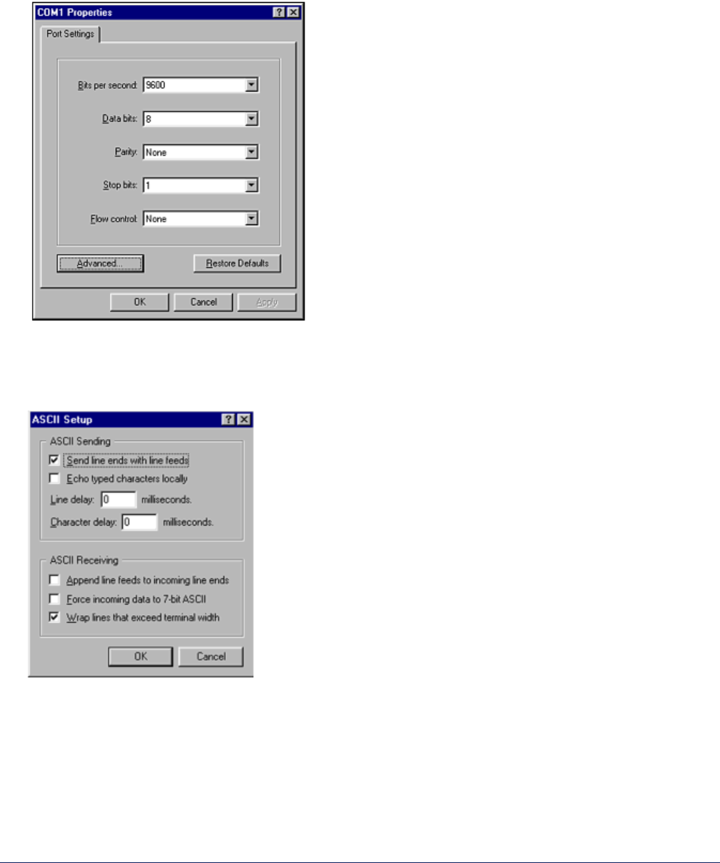
2. Set the following connection properties; then connect:
COM port (For example, COM1 or COM2, to which the MP.11/a serial port is connected.)
Bits per second 9600
Data bits 8
Stop bits 1
Flow control none
Parity none
Line ends carriage return with line feed
3. Press the RESET button on the indoor MP.11/a unit. For the outdoor MP.11/a unit, disconnect and reconnect
power. The terminal program displays Power On Self Test (POST) messages. After approximately 90
seconds it displays:
Please enter password:
4. Enter the password. The default password is public.
You can now use the CLI.
MP.11 and MP.11/a Quick Install Guide
Chapter 3. Management Overview 31
HyperTerminal Connection Properties
The serial connection properties can be found in HyperTerminal as follows:
1. Start HyperTerminal and select Properties from the File menu.
2. In the Connect using: drop-down list, select Direct to Com1 (depending upon the COM port you use) and
click Configure…; a window such as the following is displayed.
3. Make the necessary changes and click OK.
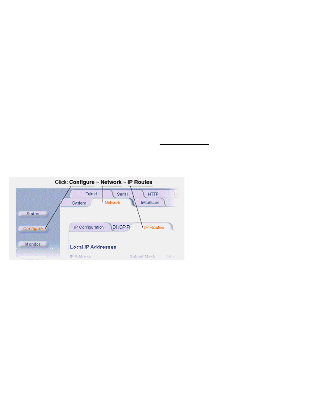
4. From the Hyperterminal Properties window, click the Settings tab; then click ASCII Setup…; a window such
as the following is displayed.
5. Ensure that Send line ends with line feeds is selected and click OK.
6. Click OK again to exit the Properties window.
HyperTerminal is now correctly configured.
MP.11 and MP.11a Installation and Management
Chapter 2. Installation 32
Chapter 4. Basic Management
This chapter describes the initial setup of the MP.11/a, which lets you configure and monitor the basic features of
the MP.11/a. In most cases, configuring these basic features is sufficient.
A full overview of the Web Interface is provided in “Chapter 5. Web Interface” on page 43; “Glossary” on page
137 provides a brief explanation of the terms used.
For CLI commands you can use for basic management, see “Command Line Interface“ on page 94.
The following topics are discussed in this chapter:
• Rebooting and Resetting on page 33
• General Settings on page 34
• Monitoring Settings on page 39
• Security Settings on page 41
• Upgrading the MP.11/a on page 42
To use the Web Interface for configuration and management, you must access the MP.11/a. With ScanTool you
can determine the unit’s current IP address. Then enter http://<ip address> in your Web browser. See “Chapter
3. Management Overview” on page 23 for details.
The Web Interface consists of Web page buttons and tabs. A tab can also contain sub-tabs. The following figure
shows the convention used to guide you to the correct tab or sub-tab.
The Web Interface also provides online help, which is stored on your computer (see “Installing Documentation
and Software” on page 21 for details).
MP.11 and MP.11/a Quick Install Guide
Chapter 5. Web Interface 33
REBOOTING AND RESETTING
All configuration changes require a restart unless otherwise stated. New features explicitly state whether a reboot
is required or not. You can restart the MP.11/a I any one of the methods described in the following sub-sections.
Most changes you make become effective only when the MP.11/a is rebooted. A reboot stores configuration
information in non-volatile memory and then restarts the MP.11/a with the new values (see “Soft Reset to Factory
Default” on page 34).
In some cases, the MP.11/a reminds you that a reboot is required for a change to take effect. You need not
reboot immediately; you can reboot after you have made all your changes.
Note: Saving of the MP.11/a configuration occurs only during a controlled reboot or by specifically issuing the
CLI Save command. If you make changes to settings without a controlled reboot (command) and you
have not issued the Save command, a power outage would wipe out all changes since the last reboot.
For example, entering static routes takes effect immediately; however, the routes are not saved until the
unit has gone through a controlled reboot. Proxim strongly recommends saving your settings immediately
when you finish making changes.
Rebooting
When you reboot, the changes you have made become effective and the MP.11/a is restarted. The changes are
saved automatically in non-volatile memory before the actual reboot takes place.
To reboot, click the Commands button, then the Reboot tab. Click the Reboot button.
The MP.11/a restarts the embedded software. During reboot, you are redirected to a page showing a countdown
timer, and you are redirected to the Status page after the timer counts down to 0 (zero). The CLI is disconnected
during reboot. This means that a new telnet session must be started.
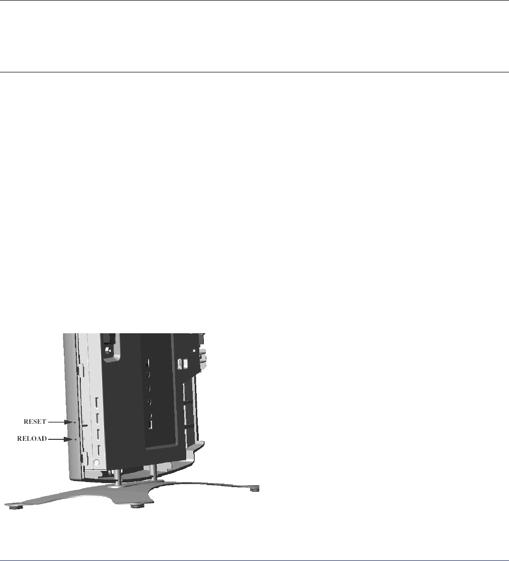
Resetting Hardware
If the MP.11/a does not respond for some reason and you are not able to reboot, you can restart by means of a
hardware reset. This restarts the MP.11/a hardware and embedded software. The last saved configuration is
used. Any changes that you have made since then are lost.
To reset the hardware, press and release the RESET button on the indoor MP.11/a unit with, for example, a
pencil. The following figure depicts the indoor MP.11/a. Use the reset command (see “Reset Command” on
page 93 to reset the outdoor MP.11/a unit.
MP.11 and MP.11/a Quick Install Guide
Chapter 5. Web Interface 34
Soft Reset to Factory Default
If necessary, you can reset the MP.11/a to the factory default settings. This must be done only when you are
experiencing problems. Resetting to the default settings requires you to again configure the MP.11/a.
To reset to factory default settings:
1. Click the Commands button, then the Reset tab.
2. Click the Reset to Factory Default button. The device configuration parameter values are reset to their
factory default values.
If you do not have access to the MP.11/a, you can use the procedure described in “Hard Reset to Factory Default”
on page 125 as an alternative.
GENERAL SETTINGS
System Status
To view the current system status, click the Status button. The Status window is the first page you see when you
log in.
See “System Status” on page 43 for more information.
MP.11 and MP.11/a Quick Install Guide
Chapter 5. Web Interface 35
System Configuration
The System Configuration page lets you change the MP.11/a’s system name, location name, and so on (see the
following System Configuration window). These details help distinguish this MP.11/a from other routers, and let
you know whom to contact in case of problems.
To go to this page, click the Configure button and the System tab.
See “Configure 1) System” on page 45 for more information.
MP.11 and MP.11/a Quick Install Guide
Chapter 5. Web Interface 36
IP Configuration
The IP Configuration window lets you change the MP.11/a IP parameters. These settings differ when the
MP.11/a is in Routing mode.
To go to this page, click the Configure button, the Network tab, then the IP Configuration sub-tab.
See “IP Configuration” on page 47 for more information.
MP.11 and MP.11/a Quick Install Guide
Chapter 5. Web Interface 37
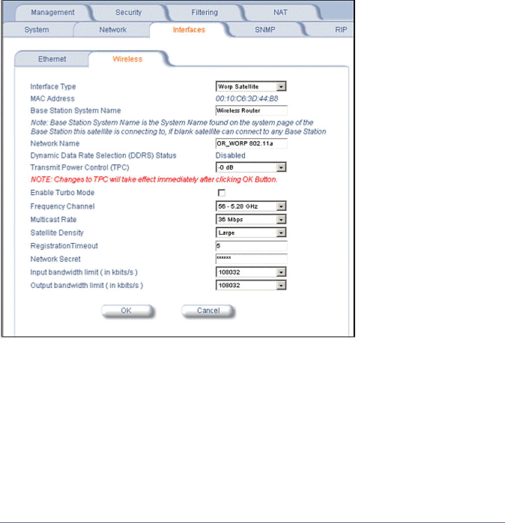
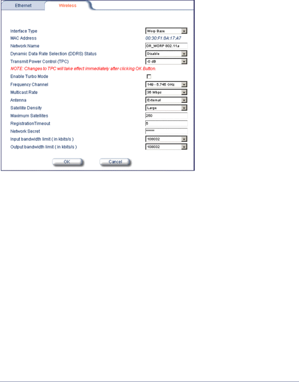
Interface Configuration
The Interfaces configuration pages let you change the MP.11/a Ethernet and wireless parameters. The Wireless
tab is displayed by default when you click the Interfaces tab.
Wireless
To configure the wireless interface, click the Configure button followed by the Interfaces tab; then click the
Wireless sub-tab.
For Base Station units, the wireless interface can be placed in either WORP Base or WORP Satellite mode
(selected from the Interface Type drop-down box). Subscriber units can be placed only in WORP Satellite mode.
(See “Wireless Outdoor Router Protocol” on page 83 for more information.)
The wireless interface settings differ per mode.
For more information, see “Wireless” on page 55.

MP.11 and MP.11/a Quick Install Guide
Chapter 5. Web Interface 38
Ethernet Port
To configure the Ethernet interface, click the Configure button, the Interfaces tab, and the Ethernet sub-tab.
You can set the Configuration parameter from this tab. Select from the following settings for the type of Ethernet
transmission.
10 Mbit/s – half-duplex
10 Mbit/s – full-duplex
10 Mbit/s – auto-duplex
100 Mbit/s – half-duplex
100 Mbit/s – full-duplex
autospeed-half-duplex
autospeed-auto-duplex
Half-duplex means that only one side can transmit at a time.
Full-duplex lets both sides transmit.
Auto-duplex selects the best transmission mode for the given configuration.
The recommended setting is auto-speed-auto-duplex.
See “Ethernet” on page 59 for more information.
MP.11 and MP.11/a Quick Install Guide
Chapter 5. Web Interface 39
MONITORING SETTINGS
The MP.11/a offers various facilities to monitor its operation and interfaces. Only the most significant monitoring
categories are mentioned here.
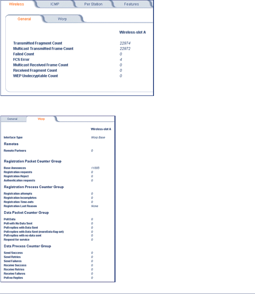
Wireless
To monitor the wireless interfaces, click the Monitor button and the Wireless tab. This tab lets you monitor the
general performance of the radio and the performance of the WORP Base or WORP subscriber interfaces.
To monitor the WORP registration/performance details, click the Monitor button, the Wireless tab, and the Worp
sub-tab.
MP.11 and MP.11/a Quick Install Guide
Chapter 5. Web Interface 40
Interfaces
To monitor transmission details, click the Monitor button and the Interfaces tab. The Interfaces tab provides
detailed information about the MAC-layer performance of the MP.11/a interface.
MP.11 and MP.11/a Quick Install Guide
Chapter 5. Web Interface 41
SECURITY SETTINGS
To prevent misuse, the MP.11/a provides wireless data encryption and password-protected access. Be sure to
set the encryption parameters and change the default passwords.
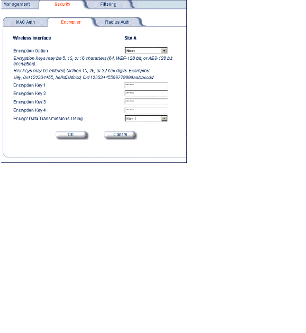
Encryption
You can protect the wireless data link by using encryption. Encryption keys can be 5 (64-bit), 13 (WEP 128-bit),
or 16 (AES 128-bit) characters in length. Both ends of the wireless data link must use the same parameter
values. Advanced Encryption Standard (AES) encryption is supported on the MP.11a only.
To set the encryption parameters, click the Configure button, the Security tab, and the Encryption sub-tab.
You can set the following encryption parameters:
Encryption Option
This parameter enables either WEP or AES encryption.
Encryption Key 1 – 4
These WEP encryption keys require an alphanumeric string. The length of the string determines the key
length. Correct string lengths are 5 or 13 alphanumeric characters, or 10 or 26 hexadecimal digits.
Encrypt Data Transmissions Using
This parameter determines which encryption key is used.

MP.11 and MP.11/a Quick Install Guide
Chapter 5. Web Interface 42
Passwords
Access to the MP.11/a is protected with passwords. The default password is public. For better security it is
recommended to change the default passwords to a value (6-32 characters) known only to you.
All passwords for the Telnet, HTTP (Web Interface), and SNMP interfaces are configured through the Configure
Æ Management Æ Passwords tab.
Note: The asterisks displayed when you enter a password are a set number that does not necessarily equal the
number of characters in the actual password string, which is intended for added security.
Changing the Telnet Password
To change the telnet password, click the Configure button and the Management tab.
Enter the new password in the Telnet (CLI) Password field; repeat it in the Confirm field and click OK.
Changing the Web Interface Password
To change the password of the Web Interface, click the Configure button and the Management tab.
Enter the new password in the HTTP (web) Password field; repeat it in the Confirm field and click OK.
Changing the SNMP Password
You can set a read and a read-and-write password for SNMP. The password used during login determines the
type of access.
You can change these passwords as follows:
1. Click the Configure button and the Management tab.
2. Enter the new password in the SNMP Read Community Password field or the SNMP Read/Wire
Community field.
3. Repeat the new password in the Confirm field.
4. Click OK when you are done.
UPGRADING THE MP.11/a
The MP.11/a is equipped with embedded software that can be updated when new versions are released.
Updating the embedded software is described in “Image File Download” on page 123. A TFTP server is provided
on the Tsunami MP.11/a Documentation and Software CD-ROM; the server is required to transfer the downloaded
file to the MP.11/a.
Notes:
• Only radios with Version 2.0 installed can be upgraded to Version 2.1.
• Upon upgrade from Version 2.0 to Version 2.1, the DFS scan can take up to 240 seconds.
To access all resolved problems in our solution database, or to search by product, category, keywords, or
phrases, go to http://support.proxim.com/. You can also find links to drivers, documentation, and downloads at
this link.
DOWNGRADING THE MP.11/a
Use the Downgrade command to downgrade to the specified version release number. The Downgrade
command currently is supported only by Tsunami MP.11/a Version 2.0.1. See “Downgrade Command” for more
information.
MP.11 and MP.11a Installation and Management
Chapter 2. Installation 43
Chapter 5. Web Interface
This section covers the Web Interface of the MP.11/a. The interface is described hierarchically according to these
buttons, which appear on the left side of the Web page:
• Status below
• Configure on page 45
• Monitor on page 84
• Commands on page 91
Help and Exit buttons also appear; click the Help button to access MP.11/a online help; click the Exit button to exit
the application.
For an introduction to the basics of MP.11/a management, see “Chapter 4. Basic Management” on page 32.
STATUS
When you click the Status button, System Status is displayed automatically. The other tab under Status is the
Event Log tab.
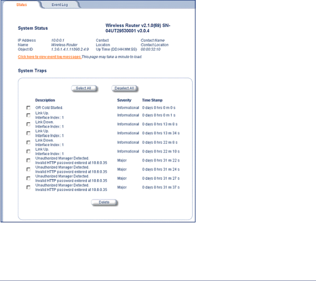
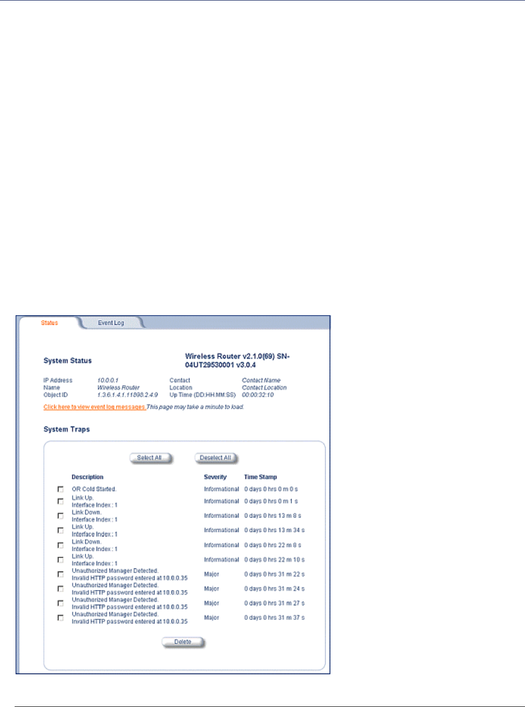
System Status
The Status tab showing the system status is displayed automatically when you log into the Web Interface. It also
is the default window displayed when you click the Status button on the left side of the window.
The Status tab shows the System Status and the System Traps.
MP.11 and MP.11/a Quick Install Guide
Chapter 5. Web Interface 44
System Status
In this section, the basic system status is shown, including the version number of the embedded software.
Systems Traps
This section shows the status of system traps. System traps occur when the MP.11/a encounters
irregularities. Deleting system traps has no effect on the operation of the MP.11/a. System traps also are sent
to an SNMP manager station (if so configured).
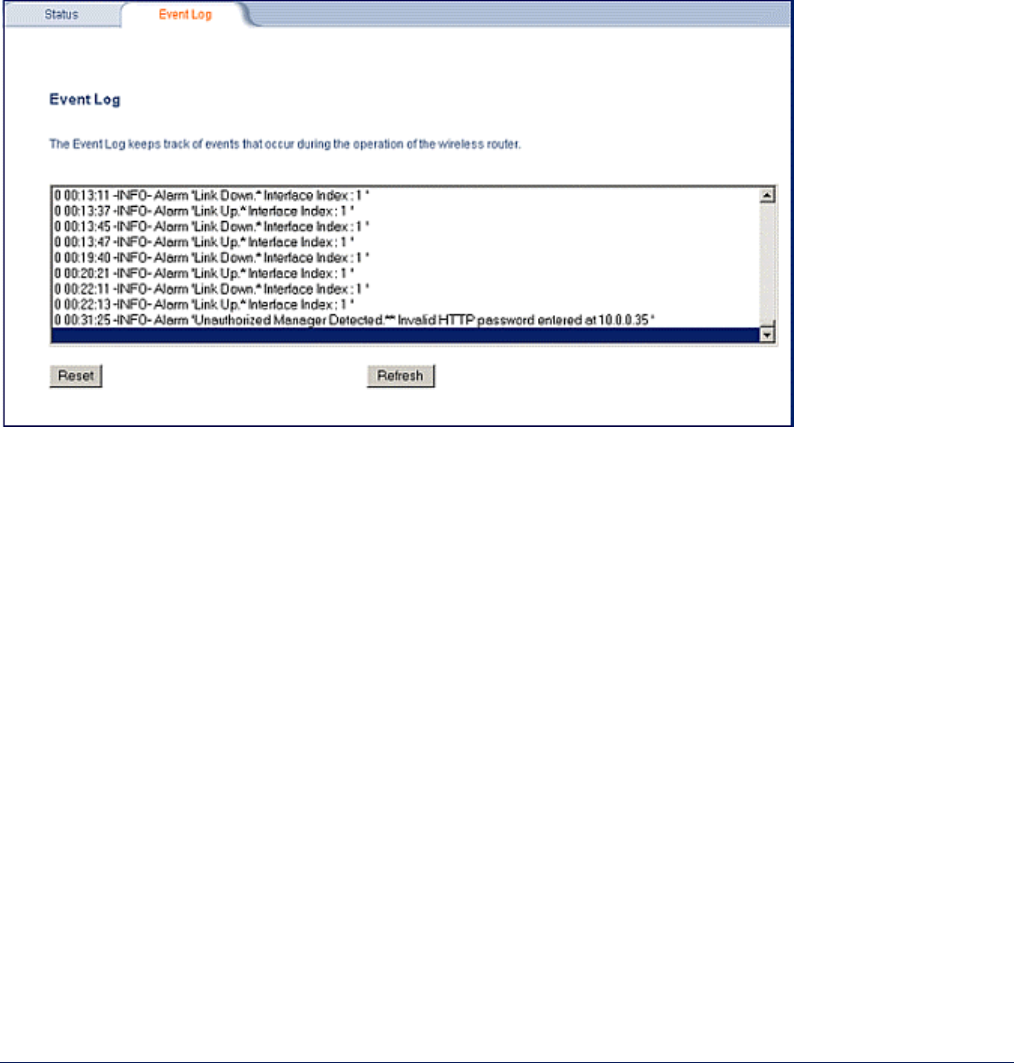
Event Log
Click the Status button and the Event Log tab to view the contents of your Event Log. The Event Log keeps
track of events that occur during the operation of the Tsunami MP.11/a. The Event Log displays messages that
may not be captured by System Traps, such as the Transmit Power for the Frequency Channel selected.
MP.11 and MP.11/a Quick Install Guide
Chapter 5. Web Interface 45
CONFIGURE
Use the Configure section to change the settings of the MP.11/a. There are 10 tabs in this section.
Note: The Intra-Cell Blocking tab is available for Base Stations in Bridge mode only. The NAT tab is available for
SUs in Routing mode only.
1. System below
2. Network on page 47
3. Interfaces on page 55
4. SNMP on page 60
5. RIP on page 61
6. Management on page 64
7. Security on page 67
8. Filtering on page 70
9. Intra-Cell Blocking on page 75
10. NAT (Network Address Translation) on page 79
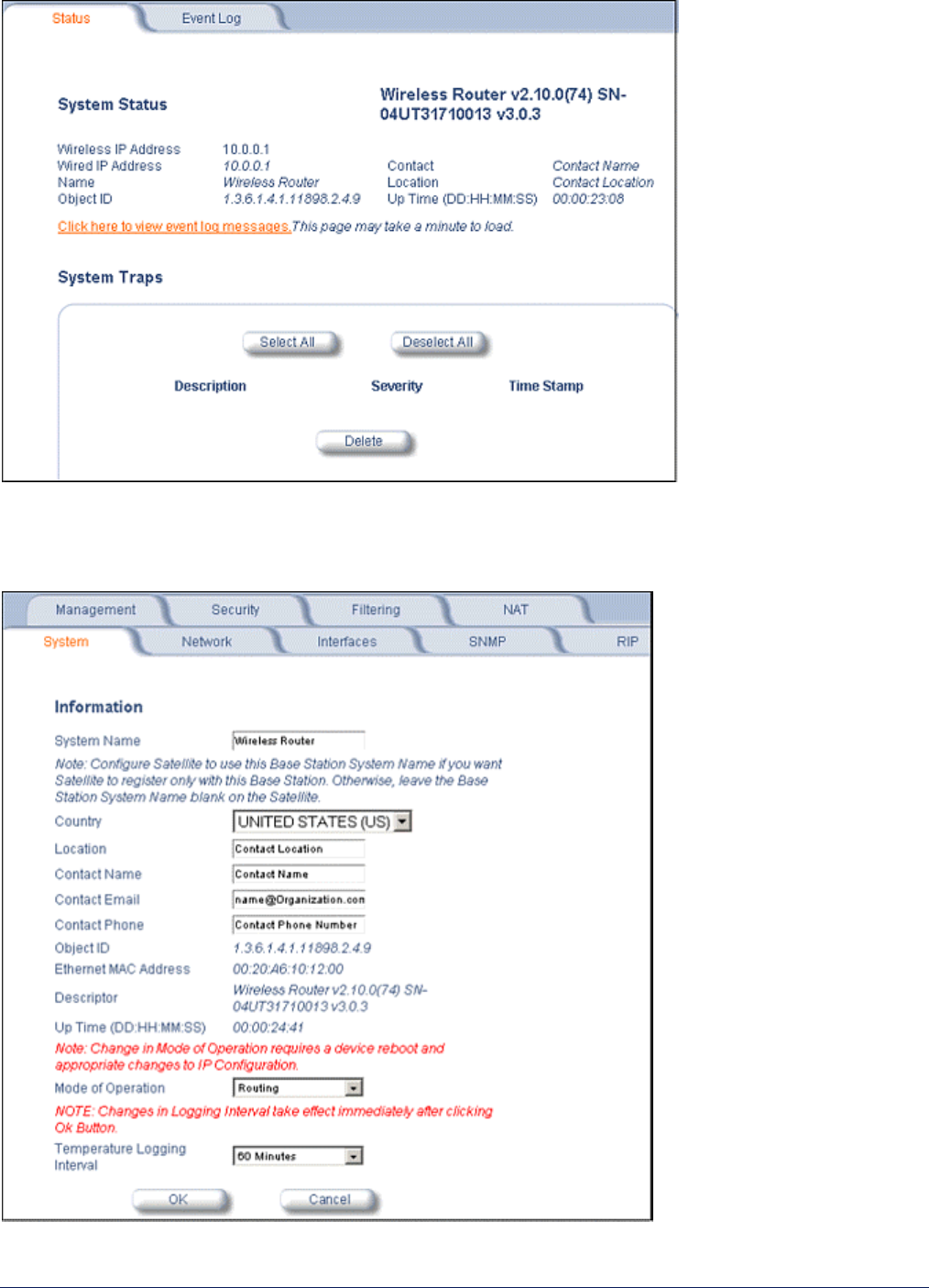
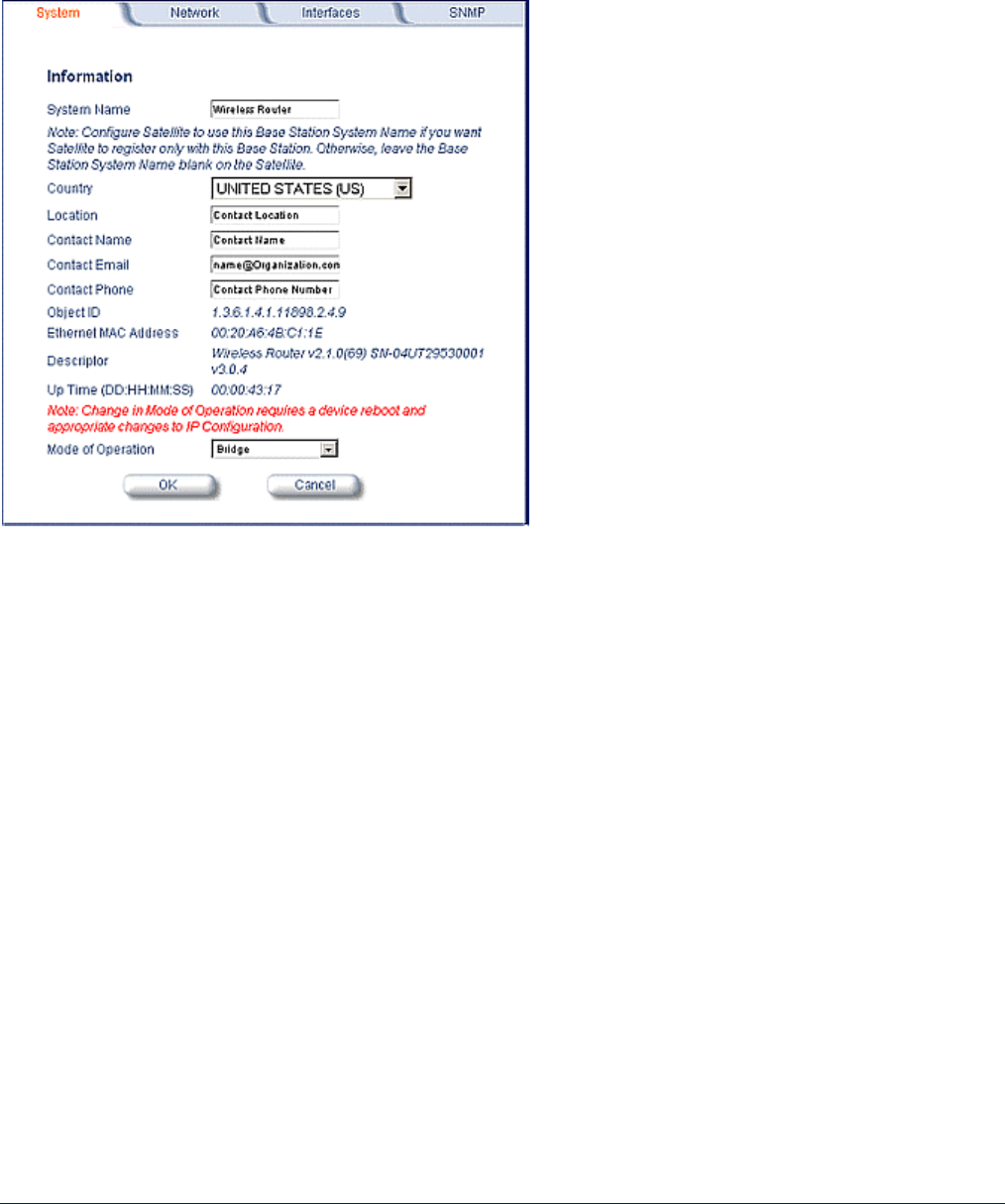
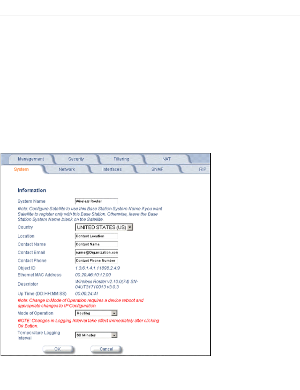
1) System
The System configuration page lets you change the MP.11/a’s System Name, Location, and so on. These details
help you to distinguish the MP.11/a from other routers and let you know whom to contact in case you experience
problems.
Click the Configure button and the System tab; the following window is displayed.
In this window, you can view or change the basic system information. Mode of Operation sets the MP.11 as
bridge (layer 2) or as router (layer 3).

MP.11 and MP.11/a Quick Install Guide
Chapter 5. Web Interface 46
You can enter the following details:
System Name
This is the system name for easy identification of the MP.11/a Base Station or SU.
Use the system name of a Base Station to configure the Base Station System Name parameter on an SU if
you want the SU to register only with this Base Station. If the Base Station System Name is left blank on
the SU, it can register with any Base Station that has a matching Network Name and Network Secret.
Country (Tsunami MP.11a units only)
The Dynamic Frequency Selection (DFS) and Transmit Power Control (TPC) features are enabled
automatically when you choose a country with a regulatory domain that requires them. The Country
selection pre-selects and displays only the allowed frequencies for the selected country. Click the Configure
button, the Interfaces tab, and the Wireless sub-tab to see the channel/frequency list.
Note: MP.11a radios sold in the United States are pre-configured to scan and display only the outdoor
frequencies permitted by the FCC. No other Country selections, channels, or frequencies can be
configured. MP.11a radios sold outside of the United States and Canada support the selection of a
Country by the professional installer.
Support for the 5.25 – 5.35 GHz and 5.725 – 5.825 GHz frequency bands is provided with a single country
selection, UNITED STATES (US), which does not provide DFS capability in these frequency bands.
For a non US-only device, the default country selected is United Kingdom (GB).
Notes: (1) The channel center frequencies are not regulated; only the band edge frequencies are
regulated.
(2) If, before upgrade, US was selected as a country for a non US-Only device (which is an
incorrect configuration), the country is changed automatically to United Kingdom upon upgrade.
See “Dynamic Frequency Selection” on page 82 and “Transmit Power Control” on page 57 for more
information. See “Country Code Table” on page 119 for a list of country codes.
Location
This field can be used to describe the location of the MP.11a, for example “Main Lobby.”
Contact Name, Contact Email, and Contact Phone
In these fields, you can enter the details of the person to contact.
Mode of Operation
This field lets you choose one of two operating modes: Bridge mode or Routing mode.
Temperature Logging Interval
This field lets you configure the temperature logging interval (in 5-minute intervals). See “Monitor: 12)
Temperature Log” on page 89 for more information.
The static fields on this window are described as follows:
ObjectID
This field shows the OID of the product name in the MIB.
Ethernet MAC Address
The MAC address of the Ethernet interface of the device.
Descriptor
Shows the product name and firmware build version.
Up Time
How long the device has been up and running since the last reboot.
MP.11 and MP.11/a Quick Install Guide
Chapter 5. Web Interface 47
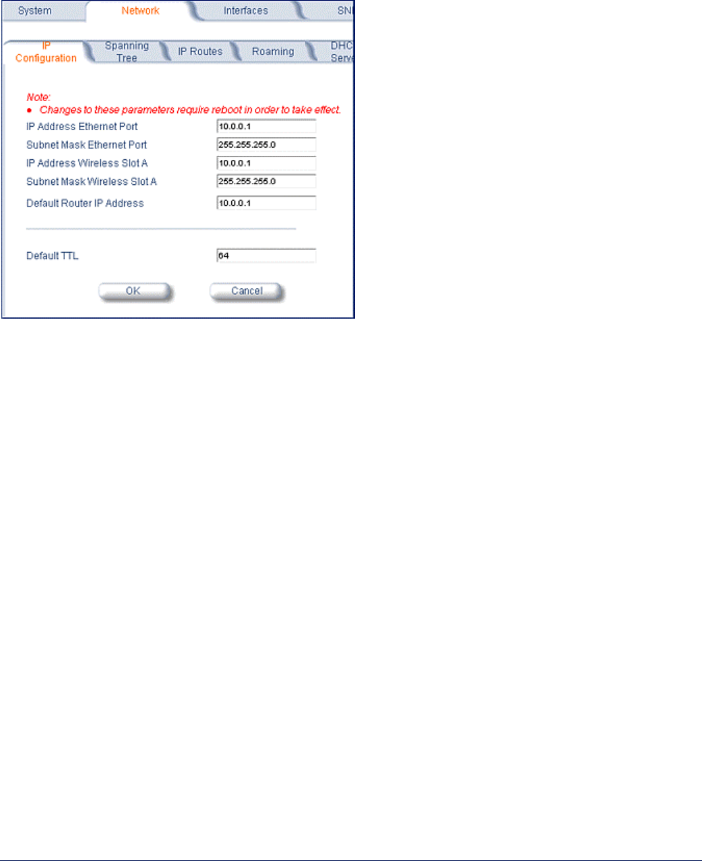
2) Network
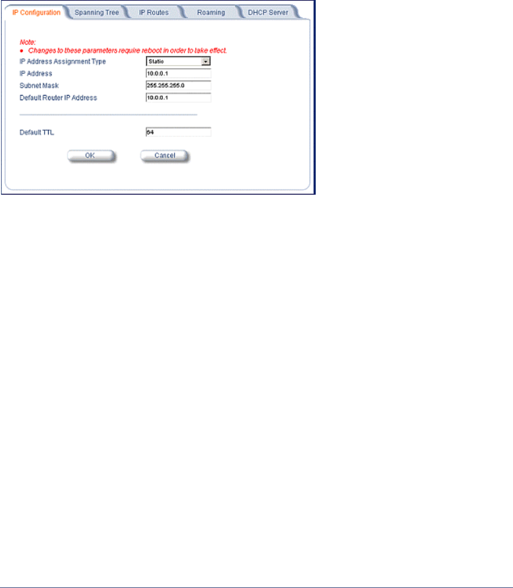
IP Configuration
The IP Configuration window lets you change the MP.11/a IP parameters. These settings differ when the
MP.11/a is in Routing mode.
Click the Configure button, the Network tab, and the IP Configuration sub-tab to view and configure local IP
address information. See “Setting the IP Address Manually” on page 24 for more information.
If the device is configured in Bridge mode, you can set the IP Address Assignment Type parameter:
• Select Static if you want to assign a static IP address to the MP.11.
• Select Dynamic to have the device run in DHCP client mode, which gets an IP address automatically from a
DHCP server over the network.
If you do not have a DHCP server or if you want to manually configure the IP settings, set this parameter to
Static.
When the MP.11/a is in Bridge mode, only one IP address is required. This IP address also can be changed with
ScanTool (see “Setting the IP Address Manually” on page 24). In Routing mode, both Ethernet and Wireless
interfaces require an IP address. You can set the remaining parameters only when the IP Address Assignment
Type is set to Static.
IP Address
The static IP address of the MP.11/a (default IP address is 10.0.0.1).
Subnet Mask
The mask of the subnet to which the MP.11/a is connected (the default subnet mask is 255.0.0.0).
Default Router IP Address
The IP address of the default gateway.
Default TTL
The default time-to-live value.
MP.11 and MP.11/a Quick Install Guide
Chapter 5. Web Interface 48
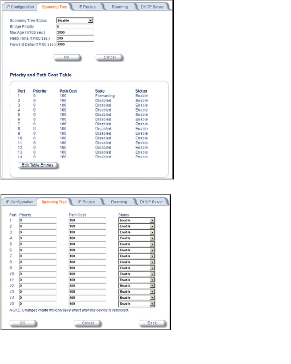
Spanning Tree
The Spanning Tree Protocol (STP) can be used to create redundant networks (“hot standby”) and to prevent
loops. If enabled, Spanning Tree prevents loops by disabling redundant links; if a link fails, it can automatically
enable a backup link.
Click Edit Table Entries to make changes; enter your changes and click OK.
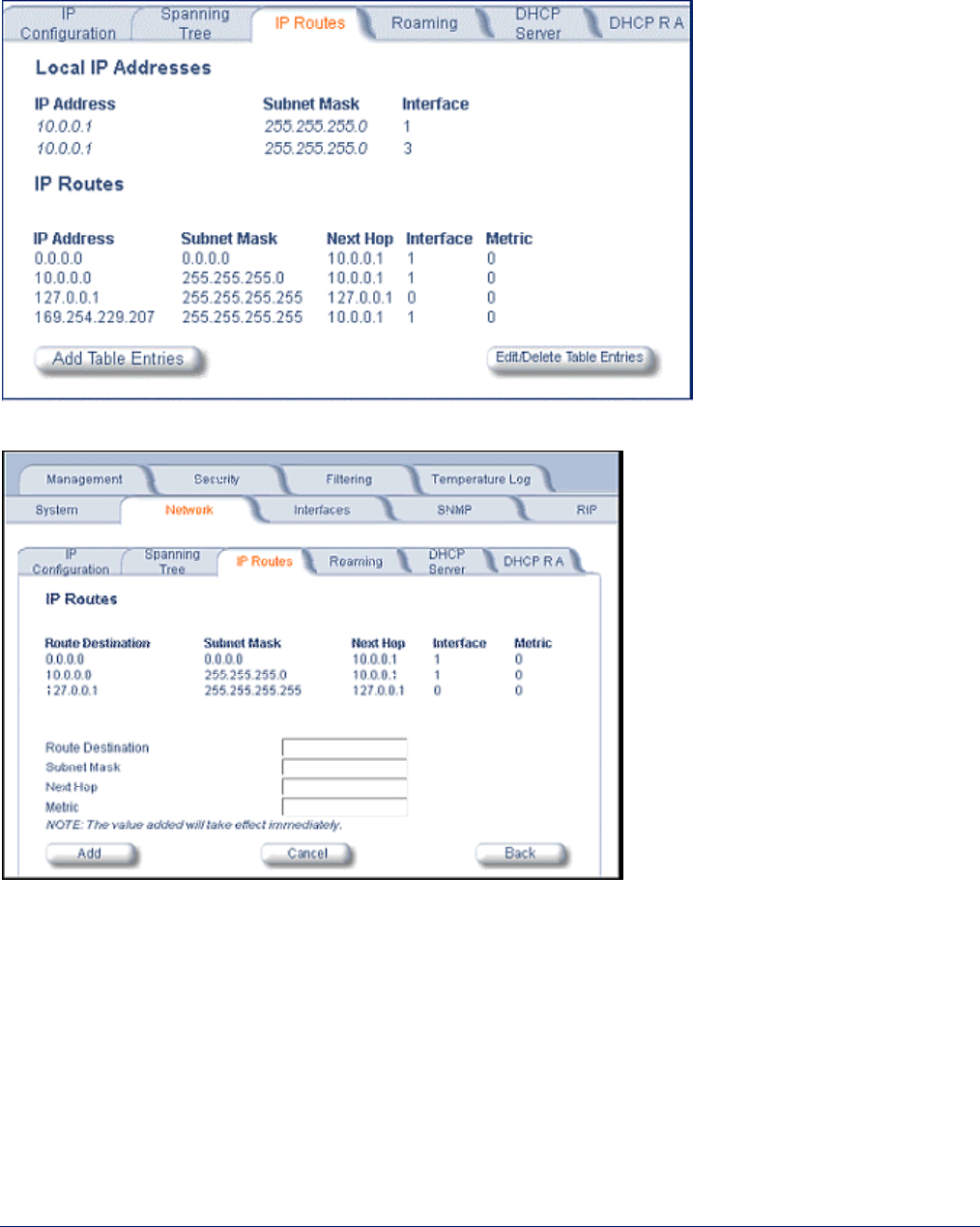
MP.11 and MP.11/a Quick Install Guide
Chapter 5. Web Interface 49
IP Routes (Routing Mode only)
Click the Configure button, the Network tab and the IP Routes sub-tab to configure IP routes. You cannot
configure IP Routes in Bridge mode. In Routing mode, the Add Table Entries and Edit/Delete Table Entries
buttons are enabled.
Click the Add button to add entries; a window such as the following is displayed:
Enter the route information and click Add. The IP Address and Subnet Mask combination is validated for a
proper combination.
Click the Edit/Delete Table Entries button to make changes to or delete existing entries.
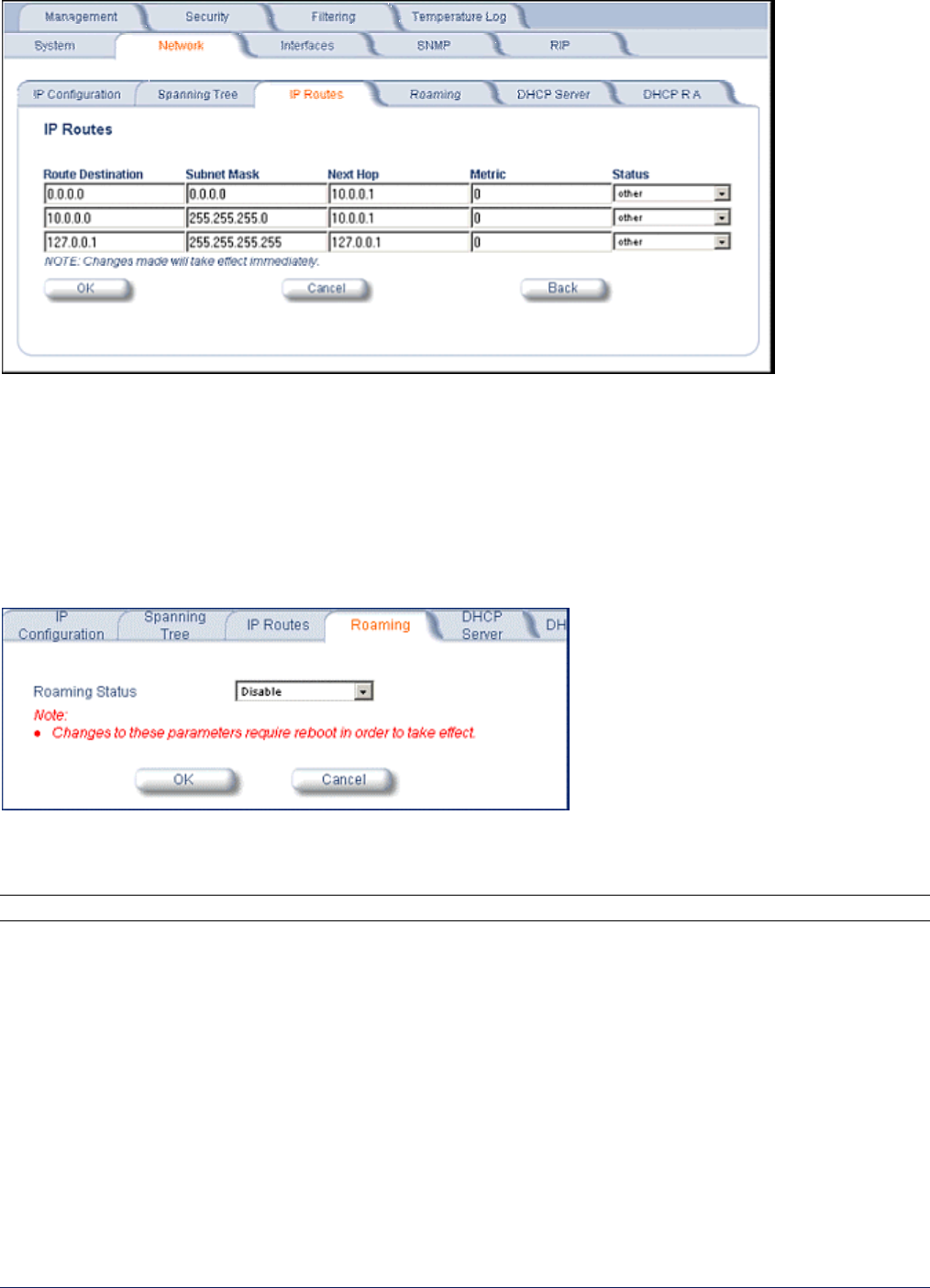
MP.11 and MP.11/a Quick Install Guide
Chapter 5. Web Interface 50
Edit the route information and click OK. The IP address and subnet mask combination is validated for a proper
combination.
Roaming
Roaming is the procedure with which an SU terminates the session with the current Base Station and starts the
registration procedure with another Base Station. Roaming provides MAC level connectivity to the SU that roams
from one Base Station to another. Proxim does not guarantee that upper layer protocol sessions will survive.
Click the Configure button, the Network tab and the Roaming sub-tab to configure Roaming.
Enable or disable the Roaming feature in the Roaming Status drop-down box. The default value is disabled.
To configure the remaining Roaming parameters, use the CLI.
Note: To enable roaming, you must enable Roaming Status on both the Base Station and the SU.

MP.11 and MP.11/a Quick Install Guide
Chapter 5. Web Interface 51
The Roaming feature lets the SU monitor local SNR and data rate for all frames received from the current Base
Station. As long as the average local SNR for the current Base Station is greater than the slow scanning
threshold, and the number of retransmitted frames is greater than the slow scanning threshold given in
percentage, the SU does not scan other channels for a better Base Station.
• The slow scanning procedure starts when the average local SNR for the current Base Station is less than or
equal to the slow scanning threshold and the number of retransmitted frames is greater than the slow
scanning threshold given in percentage. During the slow scanning procedure the SU scans the whole list of
channels while maintaining the current session uninterrupted.
• Fast Scanning is the scanning procedure performed under emergency conditions, when the average local
SNR for the current Base Station is very low, below the fast scanning threshold, and the number of
retransmitted frames is greater than the fast scanning retransmission threshold give in %, so that the current
session should terminate as soon as possible. During this procedure, the SU scans other channels as fast as
possible.
Roaming can only occur if the slow scanning or fast scanning procedure is started, under the following conditions:
1. If the roaming is started from the slow-scanning procedure (when the slow scanning procedure has completed
scanning all of the channels), the SU selects the Base Station with the best SNR value on all available
channels. The SU roams to the best Base Station only if the SNR value for the current Base Station is still
below the slow scanning SNR threshold, and best Base Station offers a better SNR value for at least roaming
threshold than the current Base Station. During roaming, the SU first ends the current session and starts the
registration procedure with the best Base Station.
2. If the roaming is started from the fast-scanning procedure (emergency conditions), the SU selects the first
Base Station that offers better SNR than the current Base Station, and starts a new registration procedure
with the better Base Station without ending the current session. The current Base Station automatically ends
the session with the SU that roamed to another Base Station after 30 seconds.
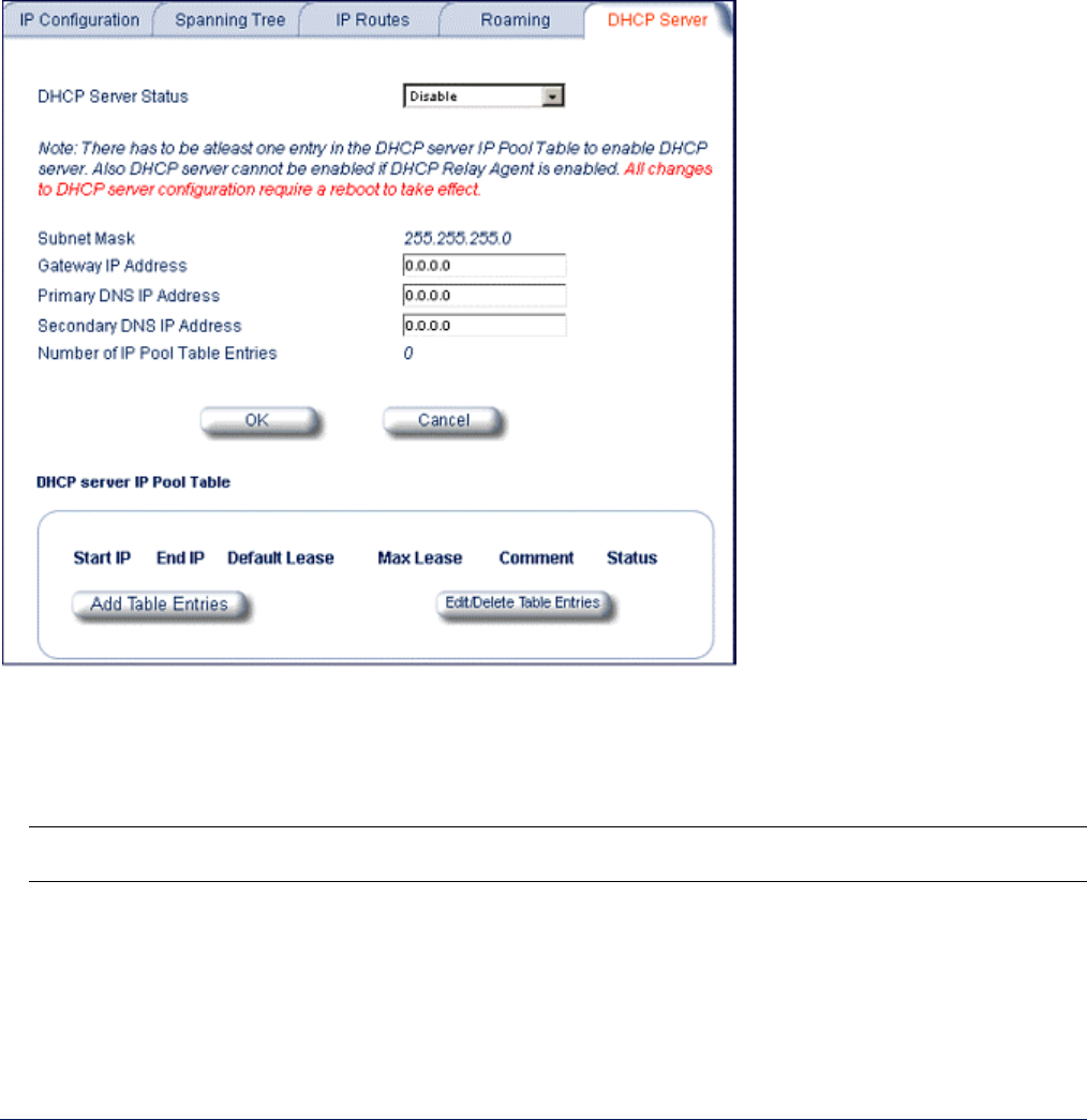
MP.11 and MP.11/a Quick Install Guide
Chapter 5. Web Interface 52
DHCP Server
Click the Configure button, the Network tab, and the DHCP Server sub-tab to enable the MP.11/a DHCP
Server.
When enabled, the DHCP server allows allocation of IP addresses to hosts on the Ethernet side of the SU or
BSU. Specifically, the DHCP Server feature lets the SU or BSU respond to DHCP requests from Ethernet hosts
with the following information:
• Host IP address
• Gateway IP address
• Subnet Mask
• DNS Primary Server IP address
• DNS Secondary Server IP address
DHCP Server Status
Verify that DHCP Relay Agent is disabled. After you have made at least one entry in the DHCP server IP Pool
Table, enable DHCP Server by selecting Enable from the DHCP Server Status pull-down menu.
Note: There must be at least one entry in the DHCP server IP Pool Table to enable DHCP server. Also DHCP
server cannot be enabled if DHCP Relay Agent is enabled.
Subnet Mask
The MP11/a supplies this subnet mask in its DHCP response to a DHCP request from an Ethernet host.
Indicates the IP subnet mask assigned to hosts on the Ethernet side using DHCP.
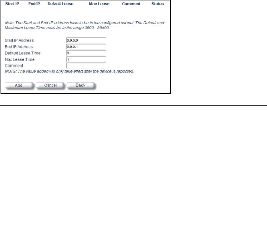
MP.11 and MP.11/a Quick Install Guide
Chapter 5. Web Interface 53
Gateway IP Address
The MP11/a supplies this gateway IP address in the DHCP response. Indicates the IP address of a router
assigned as the default gateway for hosts on the Ethernet side.
Primary DNS IP Address
The MP11/a supplies this primary DNS IP address in the DHCP response. Indicates the IP address of the
primary DNS server that hosts on the Ethernet side uses to resolve Internet host names to IP addresses
Secondary DNS IP Address
The MP11/a supplies this secondary DNS IP address in the DHCP response.
Number of IP Pool Table Entries
The number of IP pool table entries is a read-only field that indicates the total number of entries in the DHCP
server IP Pool Table. See “DHCP Server IP Pool Table” below.
DHCP Server IP Pool Table
You can configure up to 20 entries in the IP Pool Table. An IP address can be added if the entry’s network ID is
the same as the network ID of the device. To add an entry click Add Table Entries.
Enter the following parameters and click Add.
Note: After adding entries, you must reboot the unit before the values take effect.
Start IP Address
Indicates the starting IP address that is used for assigning address to hosts on the Ethernet side in the
configured subnet.
End IP Address
Indicates the ending IP address that is used for assigning address to hosts on the Ethernet side in the
configured subnet.
Default Lease Time
Specifies the default lease time for IP addresses in the address pool. The value is 3600-86400 seconds.
Max Lease Time
The maximum lease time for IP addresses in the address pool. The value is 3600-86400 seconds.
Comment
The comment field is a descriptive field of up to 255 characters.
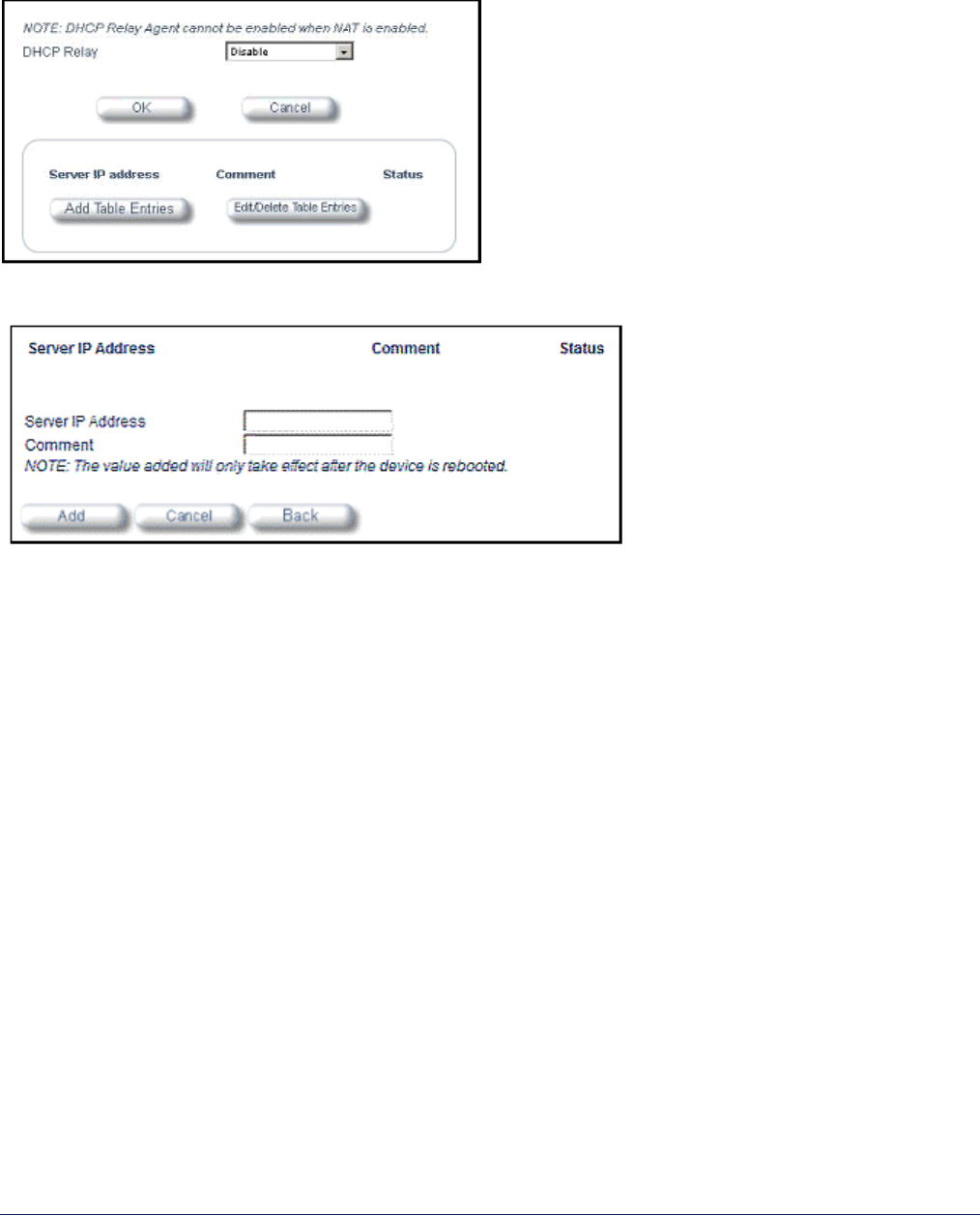
MP.11 and MP.11/a Quick Install Guide
Chapter 5. Web Interface 54
DHCP Relay Agent (Routing mode only)
Click the Configure button, the Network tab, and the DHCP RA sub-tab to enable the MP.11/a DHCP Relay
Agent. When enabled, the DHCP relay agent forwards DHCP requests to the set DHCP server.
Note that DHCP Relay Agent parameters are configurable only in Routing mode.
To add entries to the table of DHCP Relay Agents, click Add Table Entries; the following window is displayed.
Enter the Server IP Address and any optional comments; click Add.
To edit or delete entries in the table, click Edit/Delete Table Entries; make your changes and click OK.

MP.11 and MP.11/a Quick Install Guide
Chapter 5. Web Interface 55
3) Interfaces
Wireless
To configure the wireless interface, click the Configure button followed by the Interfaces tab; then click the
Wireless sub-tab.
For Base Station units, the wireless interface can be placed in either WORP Base or WORP Satellite mode
(selected from the Interface Type drop-down box). SUs can be placed only in WORP Satellite mode. (See
“Wireless Outdoor Router Protocol” on page 83 for more information.) The wireless interface settings differ per
mode.
The following is an example of a WORP Base Mode – Non-US window:
Note: Turbo mode is available only in WORP Satellite Mode in the United States.
The list of parameters to configure for registration of the SU on a Base Station are:
• Network Name
• Base Station System Name (when used)
• Channel Frequency
• Encryption (when used)
• Network Secret
Note: Encryption can impact performance with lower throughput.

MP.11 and MP.11/a Quick Install Guide
Chapter 5. Web Interface 56
You can change the following parameters:
Interface Type
The interface type can be Worp Satellite or Worp Base. *See “Wireless Outdoor Router Protocol” on page
83.)
Base Station System Name
The name found on the system page of the Base Station to which this SU is connecting. This parameter can
be used as an added security measure, and when there are multiple Base Stations in the network and you
want an SU to register with only one when it may actually have adequate signal strength for either.
If the Base Station System Name is left blank on the SU, it can register with any Base Station with a
matching Network Name and Network Secret.
Network Name
A Network Name is name given to a network so that multiple networks can reuse the same frequency without
problems. An SU can only register to a base if it has the same Network Name. The Network Name is one of
the parameters that allow a Subscriber Unit to register on a Base Station. The Base Station System Name
and Frequency Channel also are parameters to guide the SU to the proper Base Station on the network, but
they provide no security. Basic security is provided through encryption, as it causes none of the messages to
be sent in the clear. Further security is provided by mutual authentication of the Base Station and Subscriber
Unit using the Network Secret.
Dynamic Data Rate Selection (DDRS) Status (Tsunami MP.11/a only)
The WORP Dynamic Data Rate Selection (DDRS) lets the Base Station and SUs monitor the remote
average signal-to-noise ratio (SNR) and to adjust the data rate to an optimal value (to provide best possible
throughput) according to the current communication conditions during run-time.
Each frame received in the WORP protocol reports the signal and noise level in dBm at which the sender
received the previous frame from the receiver, and provides the values to calculate the signal to noise ratio
(SNR) in dB. SNR is calculated then averaged:
SNR [dB] = signal level [dBm] – noise level [dBm]
This information lets the sender adjust the transmission data rate to the optimal level to provide the best
possible throughput.
When you enable or disable WORP DDRS on the Base Station, the Base Station sends an announcement to
SUs and the SUs enable or disable WORP DDRS automatically.
Note: DDRS threshold values must be configured in the Base Station and SUs separately.
Both the Base Station and the SU monitors the remote SNR. The Base Station monitors and calculates the
average remote SNR for each SU that is registered. An SU monitors and calculates the average remote SNR
for the Base Station.
The DDRS Status is configurable only for the WORP Base Mode. For WORP Base Mode, select the DDRS
Status “Enable” or “Disable” from the drop-down box provided.
For the WORP Satellite Mode, DDRS Status is read-only parameter and its value is based upon the WORP
Base to which this SU is associated.
WORP DDRS is not supported in Turbo Mode.

MP.11 and MP.11/a Quick Install Guide
Chapter 5. Web Interface 57
Transmit Power Control
By default, the Tsunami MP.11a lets you transmit at the maximum output power for the country or regulatory
domain and frequency selected. However, with Transmit Power Control (TPC), you can adjust the output
power of the unit to a lower level in order to reduce interference from neighboring devices or to use a higher
gain antenna without violating the maximum radiated output power allowed for your country. Also, most
countries in the ETSI regulatory domain require the transmit power to be set to a 6 dB lower value than the
maximum allowed EIRP when link quality permits. You can see your unit’s current output power for the
selected frequency in the event log.
The event log shows the selected power for all data rates, so you must look up the proper data rate to
determine the actual power level. For example, the event log shows:
0 00:00:08–INFO- Final Power 6 Mb 20 dBm, MaxRD 30 dBm, MaxEdge 31 dBm, -TPC Scale 0 dBm – Ant Red 0 dBm*
0 00:00:09–INFO- 20 dBm | 20 dBm | 20 dBm | 20 dBm | 20dBm | 19 dBm | 17 dBm | 14 dBm |
The above shows that the output power is set at 20 dBm for the data rate 6, 9, 12, 18, or 24 Mbps or at 19
dBm when the selected data rate is 36 Mbps. The first line shows that 6 Mbps is selected, so the transmit
power is 20 dBm.
Note: This feature only lets you decrease your output power; it does not let you increase your output power
beyond the maximum allowed defaults for your frequency and country.
Select one of the following options and click OK at the bottom of the window. Your original output power is
adjusted relative to the value selected. The new setting takes effect immediately without rebooting:
-0 dB
-3 dB
-6 dB
-9 dB
-12 dB
-15 dB
-18 dB (minimum TPC level)
Enable Turbo Mode (MP.11a ONLY)
Check this box to enable Turbo Mode. Turbo Mode currently is supported only in the United States. Turbo
Mode utilizes two adjacent channels for wireless data transfer.
If DDRS is enabled, turbo mode cannot be enabled. The reverse is also true.
Channel Spacing
Set channel spacing to 20 MHz. (The channel spacing shows 40 MHz when turbo mode is in effect.)
Frequency Channel
The frequency channel the MP.11 (802.11b) uses for communicating with remotes. This frequency channel
can be set in the range 1 to 11 for the USA and Canada, or 1 to 13 for Europe, or 1 to 14 for Japan (see
“Radio Specifications” on page 130).
For the MP.11a (802.11a), when DFS is enabled for the selected country, the Frequency Channel field
appears as follows:
Frequency Channel – DFS, Auto selected 5.47 – 5.7 GHz
. You can monitor the DFS scan, if enabled, by refreshing the Web page.

MP.11 and MP.11/a Quick Install Guide
Chapter 5. Web Interface 58
The channels and frequencies scanned when DFS is enabled are listed in the following table.
Frequency Channels 36 Mbps 6-24 Mbps
5.47 – 5.70 GHz
5.25 – 5.35 GHz
100, 104, 108, 112, 116,
120, 124, 128, 132, 136,
140
56, 60, 64
17.4 17.4
For countries in which DFS is not enabled, the Frequency Channel list displays only the channels and
frequencies allowed for the selected country. See “Dynamic Frequency Selection” on page 82 for more
information.
Multicast Rate
The rate at which data is to be transferred. This drop down box is unavailable when DDRS is enabled.
The default data rate for the MP.11 is 11 Mbps; the default data rate for the MP.11a is 36 Mbps. The SU
must never be set to a lower data rate than the Base Station because timeouts will occur at the Base Station
and communication will fail.
Selections for Data Rate are as shown in the following table.
Date Rate Date Rate, Turbo Enabled
6 Mbps
9 Mbps
12 Mbps
18 Mbps
24 Mbps
36 Mbps
12 Mbps
18 Mbps
24 Mbps
36 Mbps
Antenna (Subscriber Units only)
Antenna displays the proper antenna port, Internal or External, for the wireless interface.
Antenna Gain (Base Station units only)
You can modify the sensitivity of the radio card when detecting radar signals in accordance with ETSI and
FCC Dynamic Frequency Selection (DFS) requirements. Given the radar detection threshold is fixed by ETSI
and the FCC and that a variety of antennas with different gains may be attached to the MP.11/a, you must
adjust this threshold to account for higher than expected antenna gains and avoid false radar detection
events. This can result in the units constantly changing frequency channels.
You can configure the threshold for radar detection at the radio card to compensate for increased external
antenna gains.
The Antenna Gain value ranges from 0 to 35. The default value is 0.
Satellite Density
The Satellite Density setting is a valuable feature for achieving maximum bandwidth in a wireless network. It
influences the receive sensitivity of the radio interface. Selections are Large, Medium, Small, Mini, and
Micro. See “Satellite Density” on page 83 for more information.
Registration Timeout
This is the registration process time-out of an SU on a Base Station. Default is 5 seconds.
Network Secret
A network secret is a secret password given to all nodes of a network. An SU can only register to a Base
Station if it has the same Network Secret. The Network Secret is sent encrypted and can be used as a
security option.
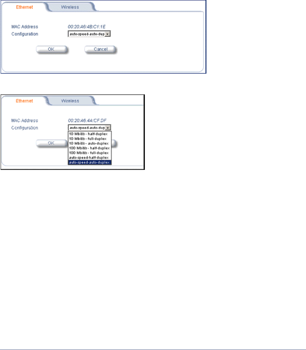
MP.11 and MP.11/a Quick Install Guide
Chapter 5. Web Interface 59
Input / Output Bandwidth Limit
These parameters limit the data traffic received on the wireless interface and transmitted to the wireless
interface, respectively. Selections are in steps of 64 Kbps from 64 to 108,032 kbps.
Ethernet
You can set the desired speed and transmission mode from this tab. The recommended setting is
auto-speed-auto-duplex.
To set the Ethernet speed, duplex mode, and input and output bandwidth limits, click the Configure button, the
Interfaces tab, and the Ethernet sub-tab.
You can set the Configuration parameter. Select from these settings for the type of Ethernet transmission
(Configuration drop-down box):
Half-duplex means that only one side can transmit at a time.
Full-duplex lets both sides transmit.
Auto-duplex selects the best transmission mode for the given configuration.
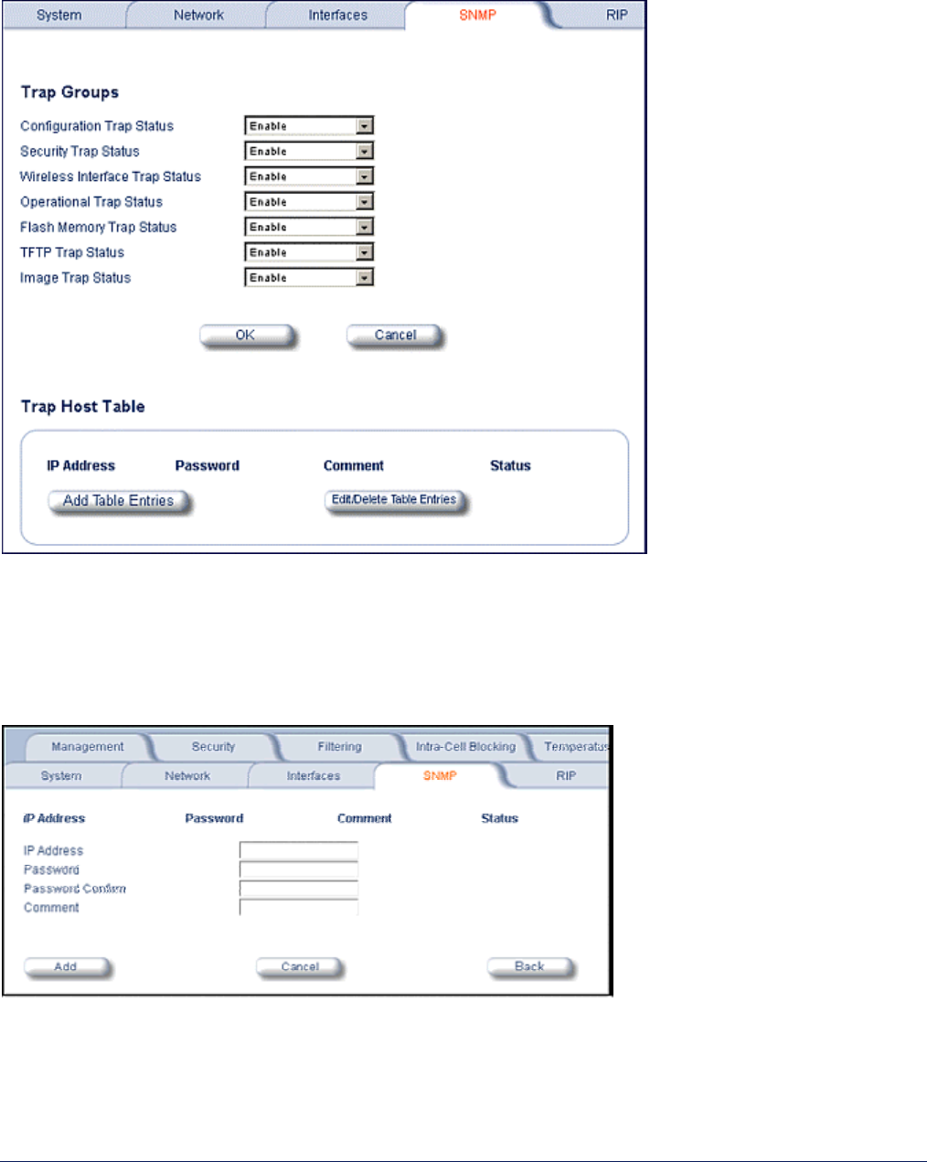
MP.11 and MP.11/a Quick Install Guide
Chapter 5. Web Interface 60
4) SNMP
Click the Configure button and the SNMP tab to enable or disable trap groups, and to configure the SNMP
management stations to which the MP11/a sends system traps.
Trap Groups
You can enable or disable different types of traps in the system. By default, all traps are enabled.
Trap Host Table
This table shows the SNMP management stations to which the MP.11/a sends system traps.
Click the Add Table Entries button to add entries to the Trap Host Table.
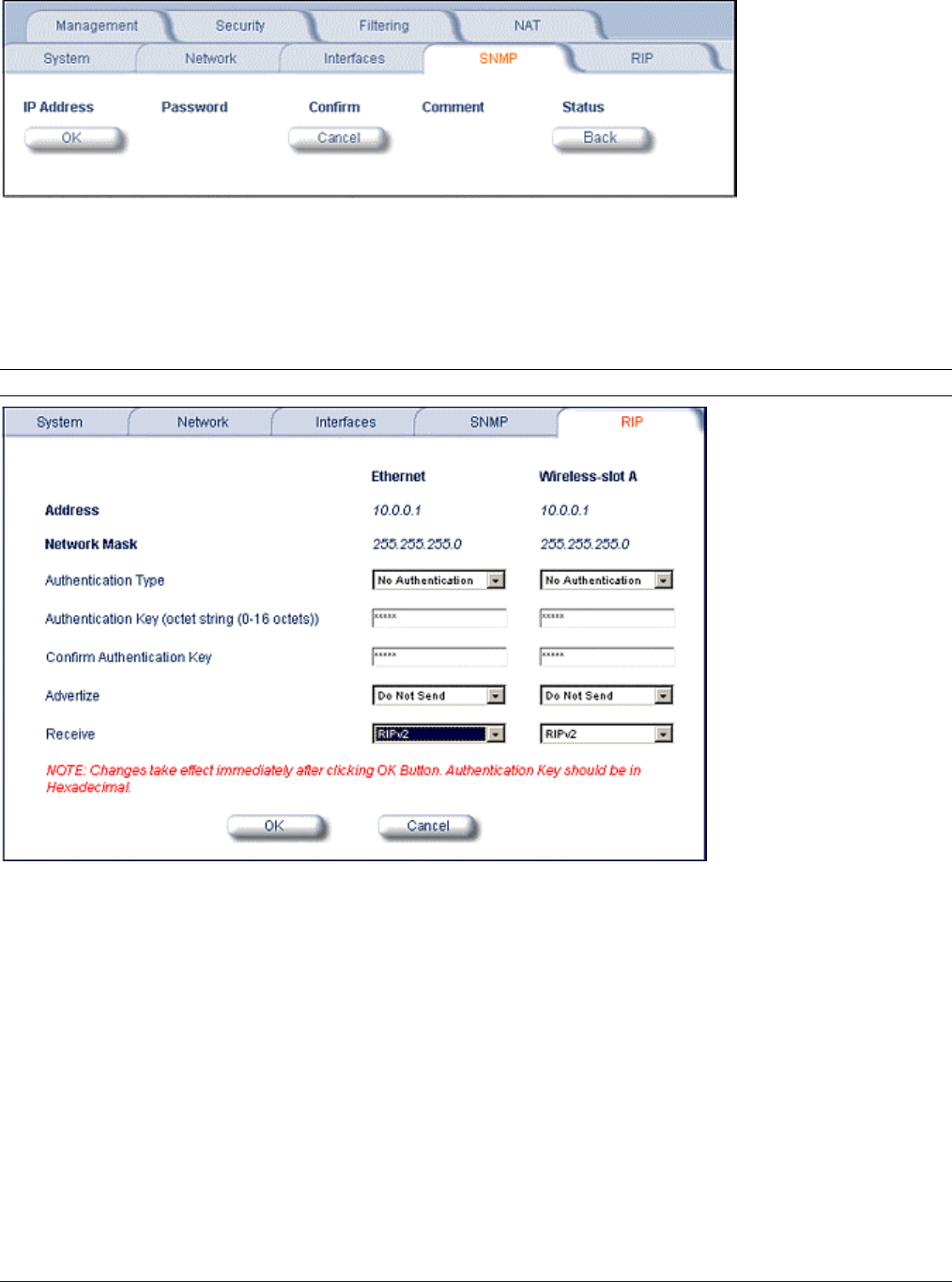
MP.11 and MP.11/a Quick Install Guide
Chapter 5. Web Interface 61
Click the Edit/Delete Table Entries button to make changes to or delete existing entries.
5) RIP
Routing Internet Protocol (RIP) is a dynamic routing protocol you can use to help automatically propagate routing
table information between routers. The Tsunami MP.11/a can be configured as RIPv1, RIPv2, RIPv1 Compatible,
or a combination of all three versions, while operating in Routing mode. In general, the Tsunami MP.11/a RIP
module is based upon RFC 1389.
Note: RIP does not work when Network Address Translation (NAT) is enabled.
Note the following:
• There is no option to turn off receiving RIP advertisements. Once the unit is in Routing mode, it receives RIP
updates when there is another RIP-enabled device advertising on your network. Although it receives and
processes these updates, it does not further propagate these updates unless configured to advertise RIP.
• The ability to enable or disable default route propagation is not user configurable. Once initialized, the
Tsunami MP.11/a uses its static default route and does not advertise this route in RIP updates. If another
router on your network is configured to advertise its default route, this route overwrites the static default route
configured on the Tsunami MP.11/a. The Tsunami MP.11/a then also propagates the new dynamic default
route throughout the network.
Be aware that, once a dynamic default route is learned, it behaves just as any other dynamic route learned
through RIP. This means if the device sending the default route stops sending RIP updates, the default route
times out and the unit has no default route to the network. Workarounds for this condition include rebooting or re-
entering a static default route. In general, the best approach is to disable the propagation of default routes on the
other routers in your network unless you understand the risks.

MP.11 and MP.11/a Quick Install Guide
Chapter 5. Web Interface 62
The following table describes the properties and features of each version of RIP supported in the Tsunami
MP.11/a.
Properties and Features of Supported RIP Versions
RIPv1 RIPv2 RIPv1 Compatible
Broadcast Multicast Broadcast
No Authentication Authentication Authentication
Class routing Classless routing (VLSM) Classless routing (VLSM)
Distance-vector protocol Distance-vector protocol Distance-vector protocol
Metric-Hops Metric-Hops Metric-Hops
Maximum Distance 15 Maximum Distance 15 Maximum Distance 15
IGP IGP IGP
RIP Example
In the following example, assume that both the BSU and the SUs all are configured in Routing mode with RIP
enabled to send and receive on both the Ethernet and Wireless interfaces. The network converges through
updates until each unit has the following routing table:
BSU
0.0.0.0 172.16.0.1 metric 1
172.16.0.0 172.16.0.20 metric 1
10.0.0.0 10.0.0.1 metric 1
100.0.0.0 10.0.0.2 metric 2
200.0.0.0 10.0.0.3 metric 2
SU1
0.0.0.0 10.0.0.1 metric 1
10.0.0.0 10.0.0.2 metric 1
100.0.0.0 100.0.0.1 metric 1
172.16.0.0 10.0.0.1 metric 2
200.0.0.0 10.0.0.2 metric 2
SU2
0.0.0.0 10.0.0.1 metric 1
10.0.0.0 10.0.0.3 metric 1
200.0.0.0 200.0.0.1 metric 1
172.16.0.0 10.0.0.1 metric 2
100.0.0.0 10.0.0.2 metric 2
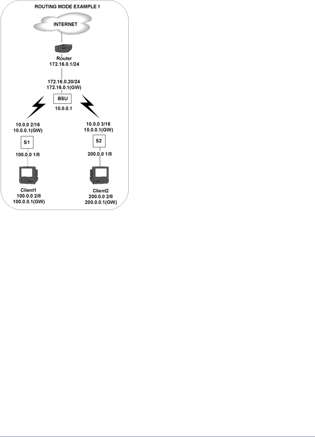
MP.11 and MP.11/a Quick Install Guide
Chapter 5. Web Interface 63
RIP Notes
• Ensure that routers on the same physical network are configured to use the same version of RIP.
• Routing updates occur every 30 seconds. It may take up to 3 minutes for a route that has gone down to
timeout in a routing table.
• RIP is limited to networks with 15 or fewer hops.
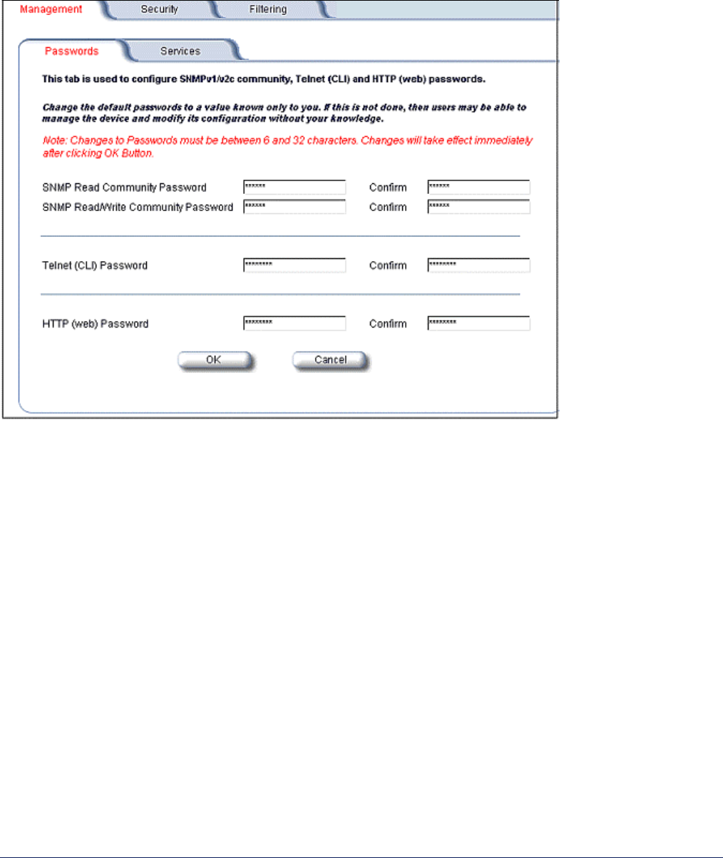
MP.11 and MP.11/a Quick Install Guide
Chapter 5. Web Interface 64
6) Management
When you click the Management button, Passwords is displayed automatically. The other tab under
Management is the Services tab.
Passwords
The Password tab lets you configure the SNMP, Telnet, and HTTP (Web Interface) passwords.
SNMP Read Community Password
The password for read access to the MP.11/a using SNMP. Enter a password in both the Password field and
the Confirm field. The default password is public.
SNMP Read/Write Community Password
The password for read and write access to the MP.11/a using SNMP. Enter a password in both the
Password field and the Confirm field. The default password is public.
Telnet (CLI) Password
The password for the CLI interface (via serial or Telnet). Enter a password in both the Password field and the
Confirm field. The default password is public.
HTTP (Web) Password
The password for the Web browser HTTP interface. Enter a password in both the Password field and the
Confirm field. The default password is public.
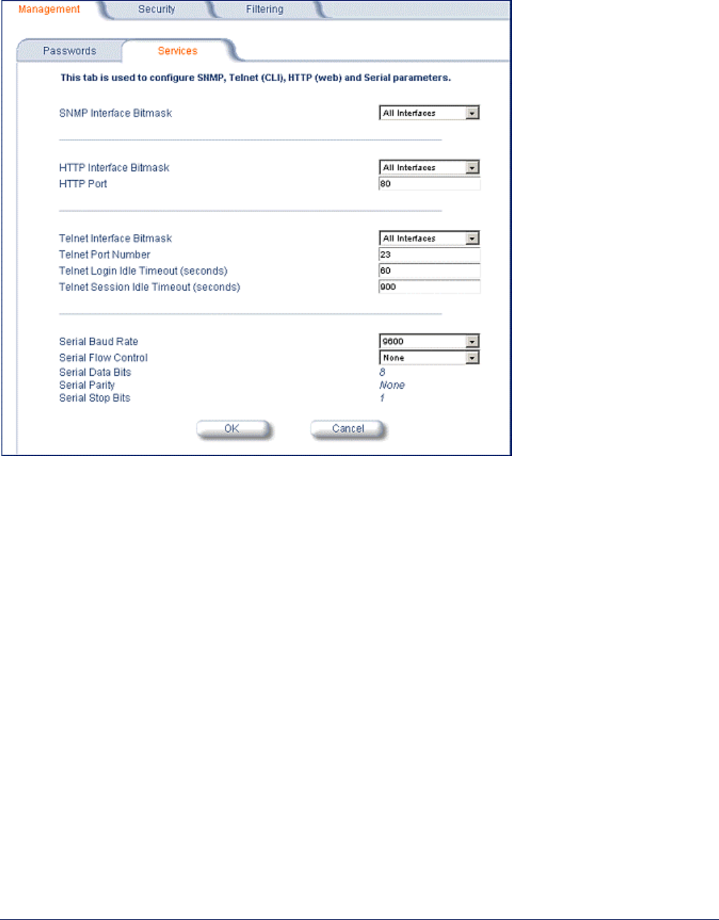
MP.11 and MP.11/a Quick Install Guide
Chapter 5. Web Interface 65
Services
The Services tab lets you configure the SNMP, Telnet, and HTTP (Web Interface) parameters. Changes to these
parameters require a reboot to take effect.
SNMP Configuration Settings
SNMP Interface Bitmask:
Configure the interface or interfaces (Ethernet, Wireless, All Interfaces) from which you will manage the
MP.11/a using SNMP. You also can select Disabled to prevent a user from accessing the MP.11/a through
SNMP.
HTTP Configuration Settings
HTTP Interface Bitmap
Configure the interface or interfaces (Ethernet, Wireless, All Interfaces) from which you will manage the
MP.11/a through the Web interface. For example, to allow Web configuration through the Ethernet network
only, set HTTP Interface Bitmask to Ethernet. You can also select Disabled to prevent a user from accessing
the MP.11/a from the Web interface.
HTTP Port
Configure the HTTP port from which you will manage the MP.11/a through the Web interface. By default, the
HTTP port is 80.