Proxim Wireless MP11R-ABG MP.11x Outdoor Wireless Ethernet System User Manual Part II
Proxim Wireless Corporation MP.11x Outdoor Wireless Ethernet System Users Manual Part II
Contents
Users Manual Part II

MP.11 and MP.11/a Quick Install Guide
Chapter 5. Web Interface 66
Telnet Configuration Settings
Note: To use HyperTerminal for CLI access, make sure to check “Send line ends with line feeds” in the ASCII
Setup window (click Properties from the HyperTerminal window; select Setup, then ASCII Setup. See
“HyperTerminal Connection Properties” on page 31 for more information).
Telnet Interface Bitmask
Select the interface (Ethernet, Wireless, All Interfaces) from which you can manage the MP.11/a through
telnet. This parameter can also be used to disable telnet management.
Telnet Port Number
The default port number for Telnet applications is 23. However, you can use this field if you want to change
the Telnet port for security reasons (but your Telnet application also must support the new port number you
select).
Telnet Login Timeout (seconds)
Enter the number of seconds the system is to wait for a login attempt. The MP.11/a terminates the session
when it times out. The range is 1 to 300 seconds; the default is 30 seconds.
Telnet Session Timeout (seconds)
Enter the number of seconds the system is to wait during a session while there is no activity. The MP.11/a
ends the session upon timeout. The range is 1 to 36000 seconds; the default is 900 seconds.
Serial Configuration Settings
The serial port interface on the MP.11/a is enabled at all times. See “Serial Port” on page 30 for information on
how to access the CLI interface through the serial port. You can configure and view following parameters:
Serial Baud Rate
Select the serial port speed (bits per second). Choose between 2400, 4800, 9600, 19200, 38400, or 57600;
the default Baud Rate is 9600.
Serial Flow Control
Select either None (default) or Xon/Xoff (software controlled) data flow control.
To avoid potential problems when communicating with the MP.11/a through the serial port, Proxim
recommends that you leave the Flow Control setting at None (the default value).
Serial Data Bits
This is a read-only field and displays the number of data bits used in serial communication (8 data bits by
default).
Serial Parity
This is a read-only field and displays the number of parity bits used in serial communication (no parity bits by
default).
Serial Stop Bits
This is a read-only field that displays the number of stop bits used in serial communication (1 stop bit by
default).
The serial port bit configuration is commonly referred to as 8N1.
MP.11 and MP.11/a Quick Install Guide
Chapter 5. Web Interface 67
7) Security
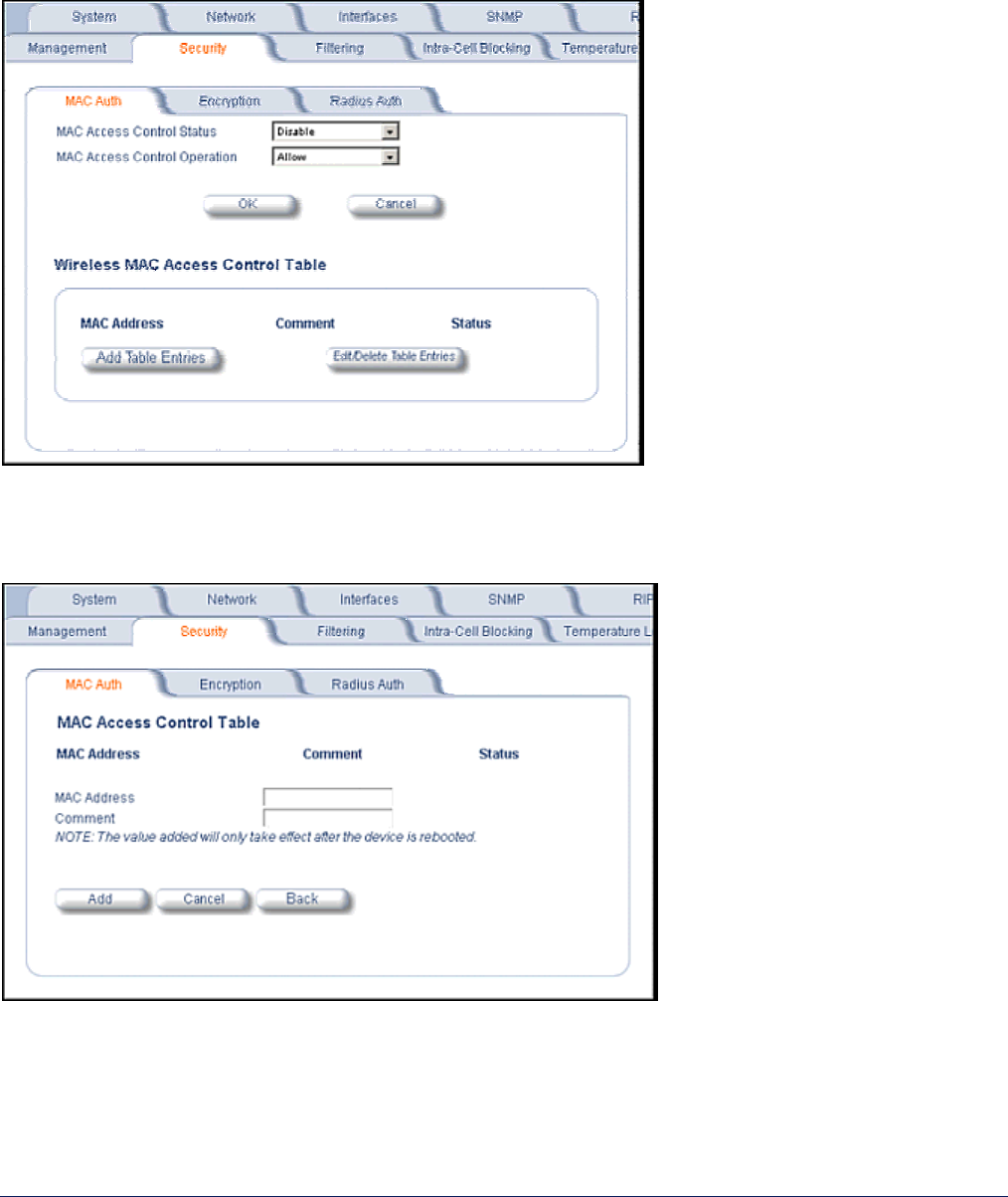
MAC Authentication
Click the Configure button, the Security tab, and the MAC Auth sub-tab to build a list of authorized wireless
stations that can register at the MP.11/a and access the network.
MAC authentication is available only for Base Station units.
This feature is supported on the wireless interface and only wireless MAC addresses should be entered in the list.
For example, build a list of the wireless MAC addresses on the Base Station for the authorized SUs.
To add table entries, click the Add Table Entries button; a window such as the following is displayed:
Enter the MAC address and any comment, then click Add.
To edit or delete table entries, click the Edit/Delete Table Entries button; make your corrections in the window
displayed and click OK.
MP.11 and MP.11/a Quick Install Guide
Chapter 5. Web Interface 68
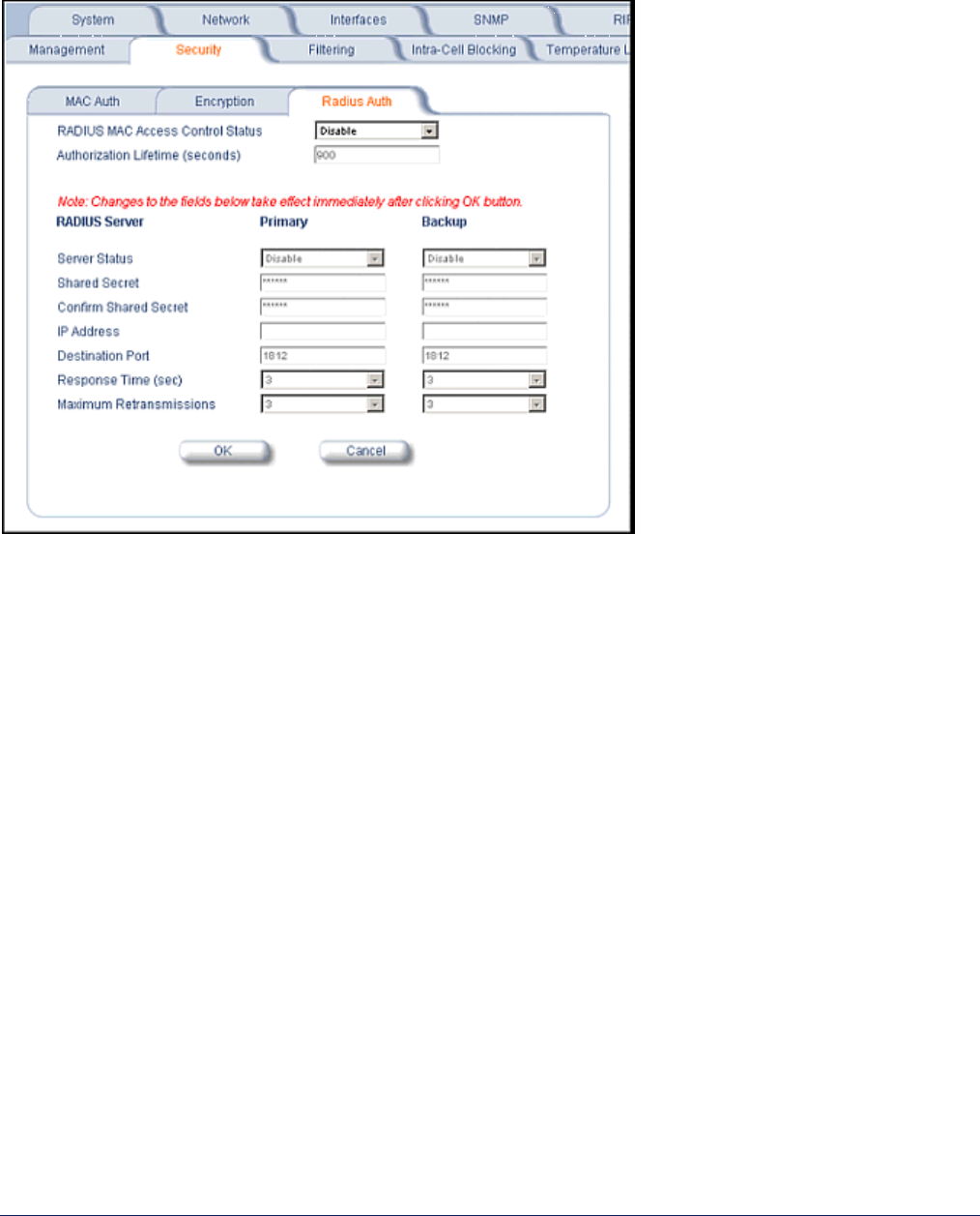
RADIUS Authentication
Click the Configure button, the Security tab, and the Radius Auth sub-tab to set the IP address of the RADIUS
server containing the central list of MAC addresses that are allowed to access the network.
RADIUS authentication is available only for Base Station units.
In large networks with multiple MP.11/a devices, you can maintain a list of MAC addresses on a centralized
location using a RADIUS authentication server that grants or denies access. If you use this kind of
authentication, you must specify at least the primary RADIUS server. The backup RADIUS server is optional.
MP.11 and MP.11/a Quick Install Guide
Chapter 5. Web Interface 69
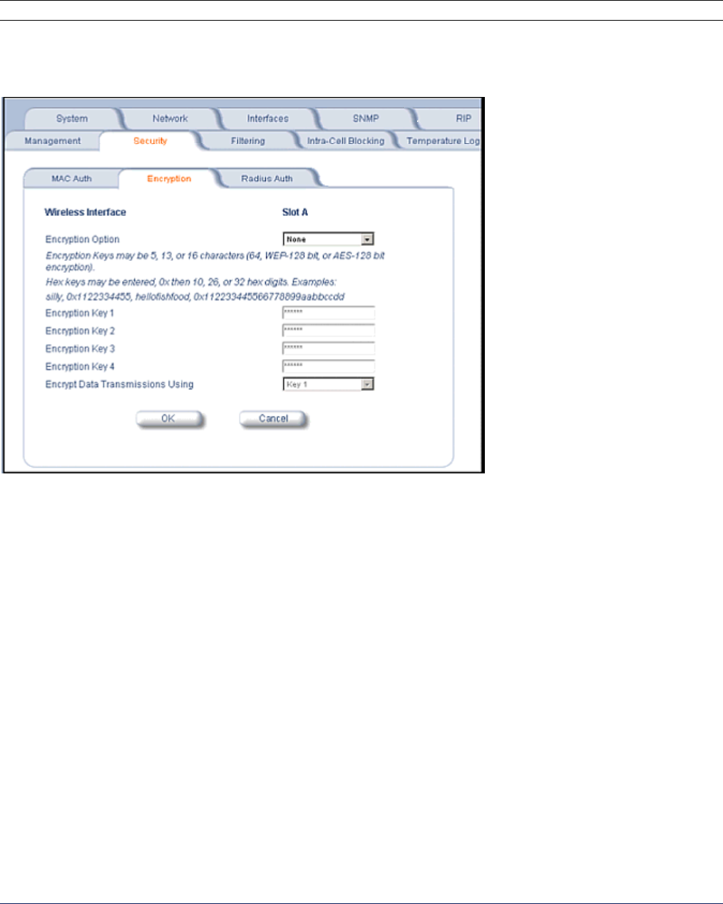
Encryption
You can protect the wireless data link by using encryption. Encryption keys can be 5 (64-bit), 13 (WEP 128-bit),
or 16 (AES 128-bit) characters in length. Both ends of the wireless data link must use the same parameter
values.
Note: Advanced Encryption Standard (AES) encryption is supported on the MP.11a only.
Click the Configure button, the Security tab, and the Encryption sub-tab to set encryption keys for the data
transmitted and received by the MP.11/a. Note that all devices in one network must use the same encryption
parameters to communicate to each other.
MP.11 and MP.11/a Quick Install Guide
Chapter 5. Web Interface 70
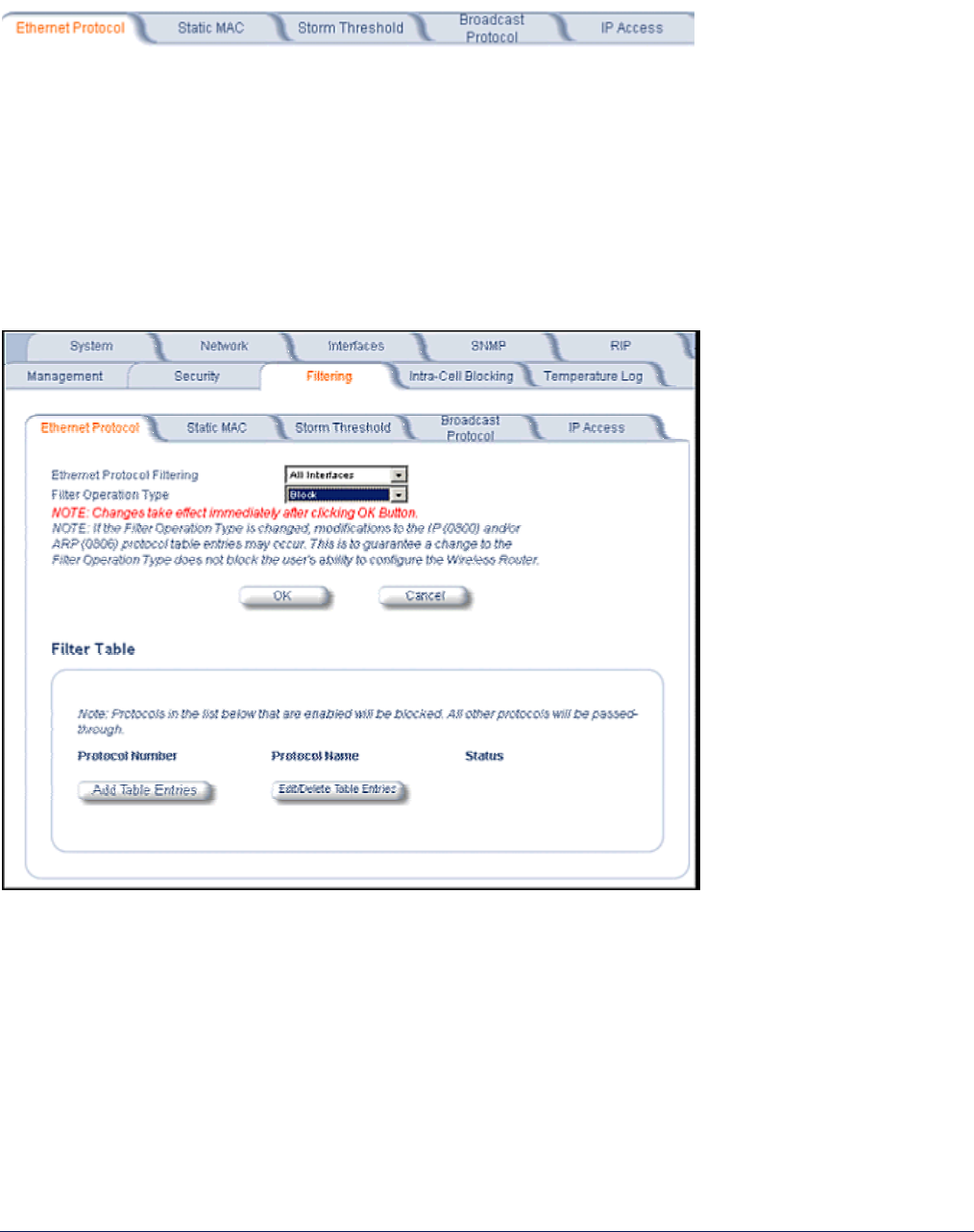
8) Filtering
Click the Configure button and the Filtering tab to configure packet filtering. Packet filtering can be used to
control and optimize network performance. Filtering sub-tabs are as follows:
Ethernet Protocol
The Ethernet Protocol filter blocks or forwards packets based upon the Ethernet protocols they support. Click the
Configure button, the Filtering tab, and the Ethernet Protocol sub-tab to enable or disable certain protocols in
the table. Entries can be selected from a drop-down box.
• To add an entry to the table, click Add Table Entries, select the protocol name from the drop-down box and
click the Add button.
• To edit or delete table entries, click Edit/Delete Table Entries, make your changes or deletions, and click
OK.
Ethernet Protocol Filtering
Blocks or forwards packets based upon the Ethernet protocols they support:
Ethernet: Packets are examined at the Ethernet interface.
Wireless: Packets are examined at the Wireless interface.
All Interfaces: Packets are examined at both interfaces.
Disabled: The filter is not used.
Filter Operation Type
Passthru: Only the enabled Ethernet protocols listed in the Filter table pass through the bridge.
Block: the Bridge blocks enabled Ethernet protocols listed in the Filter table.
MP.11 and MP.11/a Quick Install Guide
Chapter 5. Web Interface 71
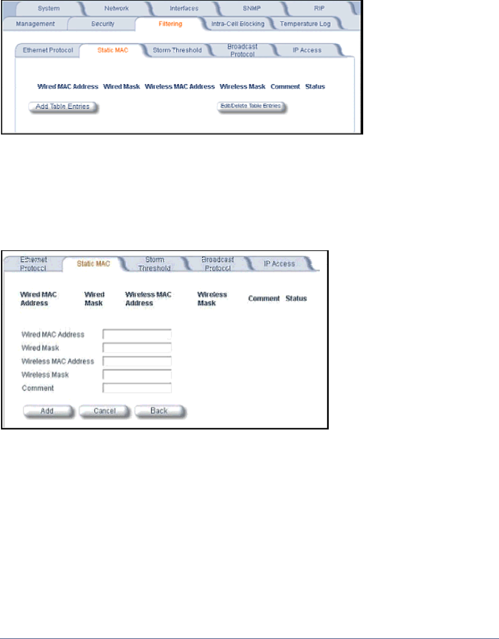
Static MAC Pair Filtering
The Static MAC Address filter optimizes the performance of a wireless (and wired) network. Click the Configure
button, the Filtering tab, and the Static MAC sub-tab to access the Static MAC Address filter.
The filter is an advanced feature that lets you limit the data traffic between two specific devices (or between
groups of devices based upon MAC addresses) through the wireless interface of the MP.11/a. For example, if
you have a server on your network with which you do not want wireless clients to communicate, you can set up a
static MAC filter to block traffic between these devices. The Static MAC Filter Table performs bi-directional
filtering. However, note that this is an advanced filter and it may be easier to control wireless traffic through other
filter options, such as Protocol Filtering.
To add the entries to Filter table, click the Add Table Entries button.
After entering the data, click the Add button.
The entry is enabled automatically when saved.
To edit an entry, click Edit. To disable or remove an entry, click Edit and change the Status field from Enable to
Disable or Delete.
Wired MAC Address
Enter the MAC address of the device on the Ethernet network that you want to prevent from communicating
with a device on the wireless network.
Wired Mask
Enter the appropriate bit mask to specify the range of MAC addresses to which this filter is to apply. To
specify only the single MAC address you entered in the Wired MAC Address field, enter 00:00:00:00:00:00
(all zeroes).
MP.11 and MP.11/a Quick Install Guide
Chapter 5. Web Interface 72
Wireless MAC Address
Enter the MAC address of the wireless device that you want to prevent from communicating with a device on
the wired network.
Wireless Mask
Enter the appropriate bit mask to specify the range of MAC addresses to which this filter is to apply. To
specify only the single MAC address you entered in the Wireless MAC Address field, enter 00:00:00:00:00:00
(all zeroes).
Comment
Enter related information.
Status
The Status field can show Enable, Disable, or Delete.
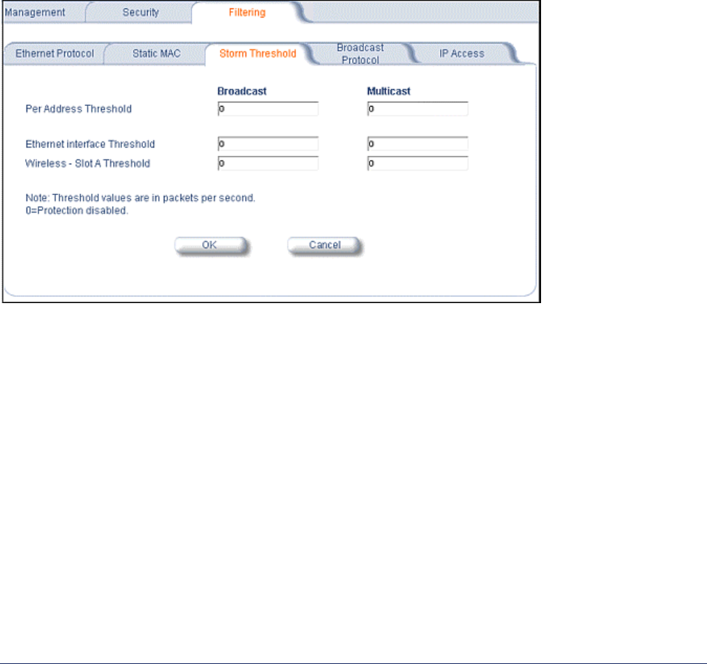
Storm Threshold
Click the Configure button, the Filtering tab, and the Storm Threshold sub-tab to use threshold limits to prevent
broadcast/multicast overload.
Storm Threshold is an advanced Bridge setup option that you can use to protect the network against data
overload by specifying:
• A maximum number of frames per second as received from a single network device (identified by its MAC
address).
• An absolute maximum number of messages per port.
The Storm Threshold parameters let you specify a set of thresholds for each port of the MP.11/a, identifying
separate values for the number of broadcast messages per second and multicast messages per second.
When the number of frames for a port or identified station exceeds the maximum value per second, the MP.11/a
ignores all subsequent messages issued by the particular network device, or ignores all messages of that type.
Per Address Threshold
Enter the maximum allowed number of packets per second.
Ethernet Threshold
Enter the maximum allowed number of packets per second.
Wireless Threshold
Enter the maximum allowed number of packets per second.
MP.11 and MP.11/a Quick Install Guide
Chapter 5. Web Interface 73
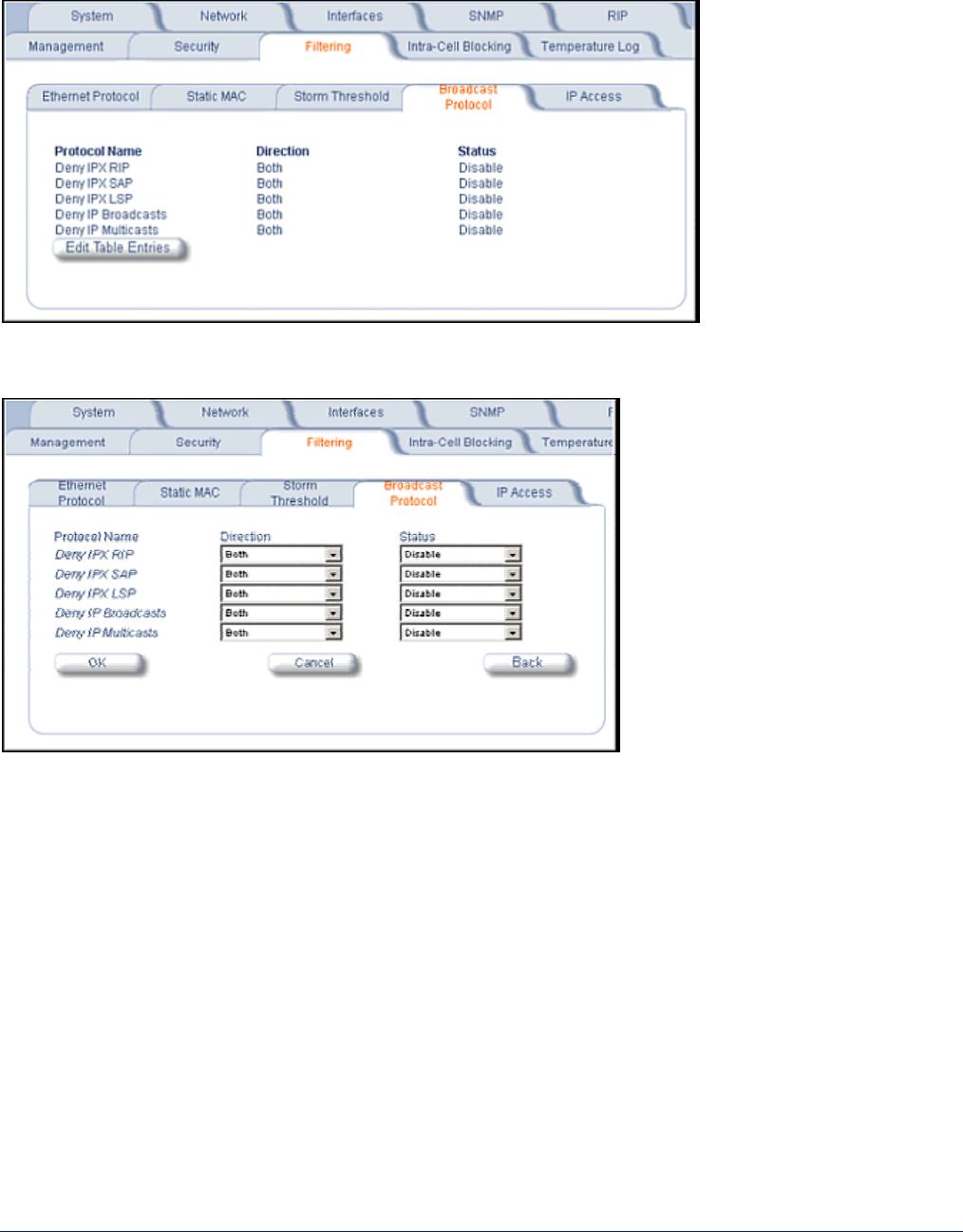
Broadcast Protocol Filtering
Click the Configure button, the Filtering tab, and the Broadcast Protocol sub-tab to deny specific IP broadcast,
IPX broadcast, and multicast traffic.
Click the Edit Table Entries button to display an editable window such as the following. You can configure
whether this traffic must be blocked for Ethernet to wireless, wireless to Ethernet, or both.
MP.11 and MP.11/a Quick Install Guide
Chapter 5. Web Interface 74
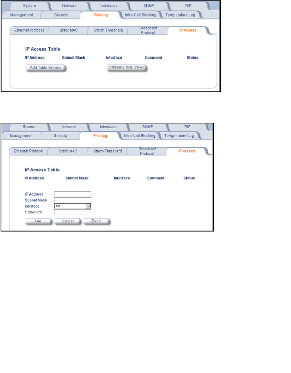
IP Access Table
Entries in this table show which wireless stations are allowed to use SNMP, HTTP, and telnet management
interfaces.
To add an entry, click the Add Table Entries button, specify the IP address and mask of the wireless stations to
which you want to grant access, and click Add. To edit or delete table entries, click the Edit/Delete Table
Entries button, make your changes, and click OK.
For example, 172.17.23.0/255.255.255.0 allows access from all wireless stations with an IP address in the
172.17.23.xxx range.
Ensure that the wireless station you use is the first entry in the table.
MP.11 and MP.11/a Quick Install Guide
Chapter 5. Web Interface 75
9) Intra-Cell Blocking (Base Station only)
The Intra-Cell Blocking feature lets traffic be blocked between two SUs registered to the same Base Station.
There are two potential reasons to isolate traffic among wireless subscribers:
• To provide better security to the subscribers by isolating the traffic from one subscriber to another in a public
space.
• To block unwanted traffic between subscribers to prevent this traffic from using bandwidth.
You can form groups of SUs at the Base Station, which define the filtering criteria. All data to or from SUs
belonging to the same group are bridged. All other data from SUs that do not belong to a particular group are
automatically forwarded through the Ethernet interface of the Base Station. If an SU does not belong to any
group, the Base Station discards the data.
You can also configure a Security Gateway to block traffic between SUs connected to different BSUs. All packets
destined for SUs not connected to the same Base Station are forwarded to the Security Gateway MAC address
(configured in the Security Gateway tab).
When you change the device from Bridge to Routing mode, Intra-Cell Blocking stops working with or without a
reboot. When you change the device from Routing to Bridge mode, Intra-Cell Blocking starts working with or
without a reboot.
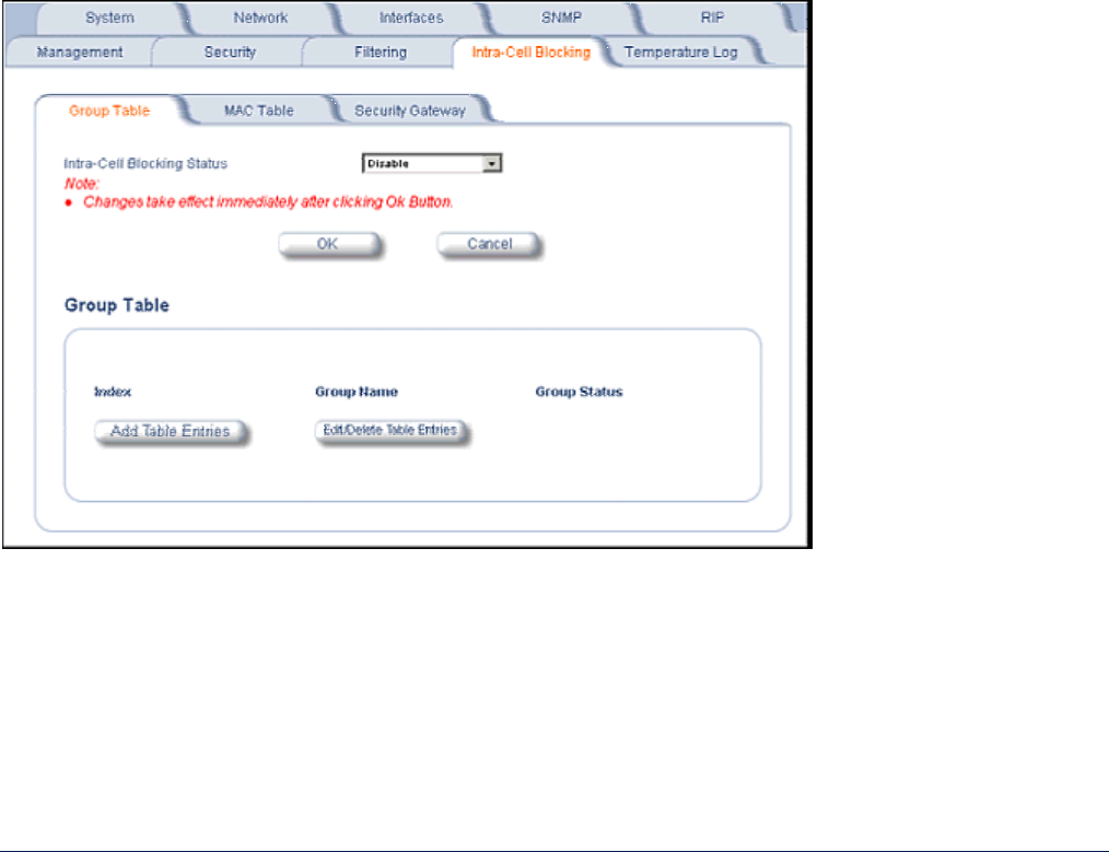
Group Table Tab
The Group Table tab lets you enable the Intra-Cell Blocking feature and to configure Intra-Cell Blocking Groups.
Intra-Cell Blocking Status
Enables or disables the Intra-Cell Blocking feature.
Group Table
Entries in this table show the Intra-Cell Blocking filter groups that have been configured. When Intra-Cell
Blocking is enabled, the Base Station Unit discards all packets coming from one SU to another SU, if both
SUs do not belong to the same filter group.
MP.11 and MP.11/a Quick Install Guide
Chapter 5. Web Interface 76
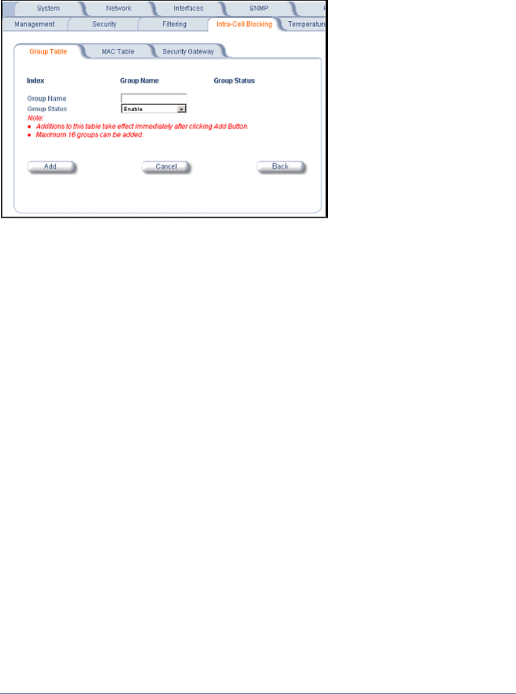
Click the Add Table Entries button to add groups.
Enter the group name, and click Add. The group is assigned an Index and appears in the Group Table. Up to 16
groups can be configured per Base Station.
You can enable, disable or delete an existing filter group by using the Edit/Delete Table Entries button.
After you have configured the groups, click the MAC Table tab to assign specific MAC addresses to an Intra-Cell
Blocking Group.
MP.11 and MP.11/a Quick Install Guide
Chapter 5. Web Interface 77
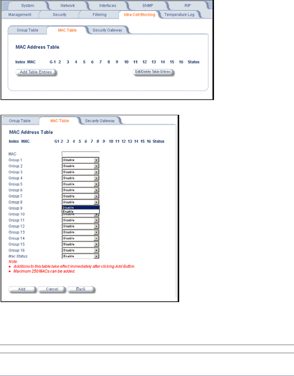
MAC Table Tab
After configuring the Intra-Cell Blocking Groups on the Group Table tab, use the MAC Table tab to assign
specific MAC addresses to an Intra-Cell Blocking Group.
Click the Add Table Entries button.
Enter the MAC address of the SU. Select Enable from the drop-down menu for the Group Index
Click Add. The MAC address is assigned to the groups. Additions to the MAC Table take effect immediately after
clicking the Add button. You can enable, disable, delete, or reassign the groups for a MAC address by using
the Edit/Delete Table Entries button.
Note: A maximum of 250 MAC addresses can be added among all filter groups.
MP.11 and MP.11/a Quick Install Guide
Chapter 5. Web Interface 78
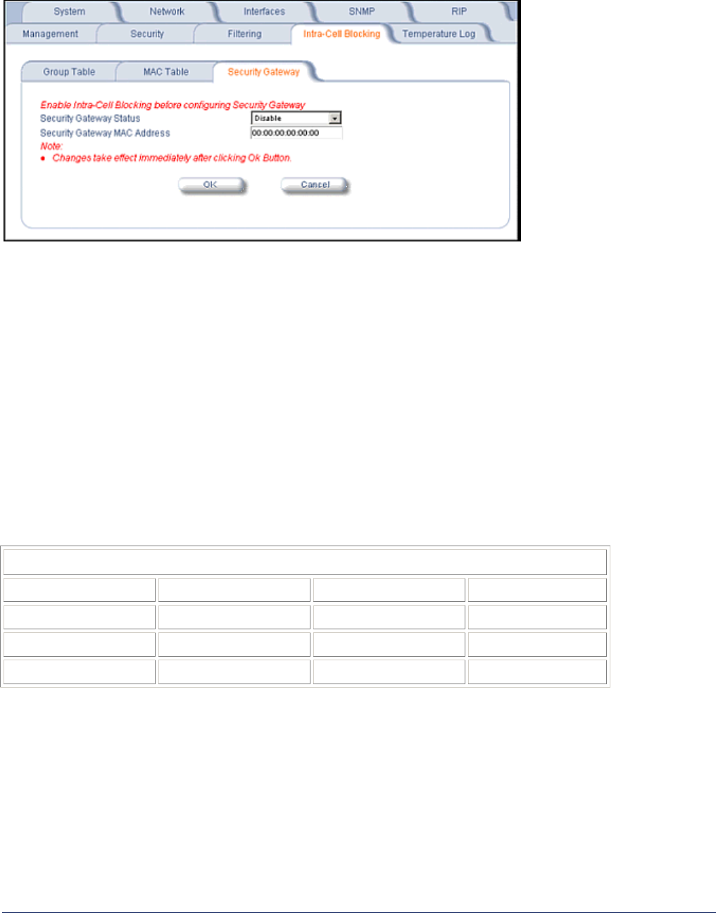
Security Gateway Tab
You can configure a Security Gateway to block traffic between SUs connected to different Base Stations. Verify
that Intra-Cell Blocking has been enabled on the Group Table tab before configuring the Security Gateway.
Security Gateway Status
Enables or disables packet forwarding to the external Security Gateway.
Security Gateway MAC Address
Lets you configure the MAC address of the external Security Gateway.
Group Rules
The following rules apply to Intra-Cell Blocking Groups:
• One SU can be assigned to more than one group.
• An SU that has not been assigned to any group cannot communicate to any other SU connected to the same
or different Base Station Unit.
Example of Intra-Cell Blocking Groups
Four Intra-Cell Blocking Groups have been configured on one Base Station Unit. SUs 1 through 6 are registered
to Base Station Unit 1. SUs 7 through 9 are registered to Base Station Unit 2.
Intra-Cell Blocking Group Example
Group 1 Group 2 Group 3 Group 4
SU 1 SU 2 SU 6 SU 8
SU 4 SU 3 SU 1 SU 9
SU 5 SU 8 SU 3 SU 2
In this example, SU 1 belongs to two groups, Group 1 and Group 3. Therefore, packets from SU 1 destined to SU
4, SU 5, SU 6, and SU 3 are not blocked. However, SU 9 belongs to group 4 only and packets from SU 9 are
blocked unless sent to SU 8 or SU 2.
MP.11 and MP.11/a Quick Install Guide
Chapter 5. Web Interface 79
10) NAT (Network Address Translation)
The NAT (Network Address Translation) feature lets hosts on the Ethernet side of the SU transparently access
the public network through the Base Station. All hosts in the private network can have simultaneous access to the
public network.
Note: The NAT tab is available for SUs in Routing mode only. The SU supports NAPT (Network Address Port
Translation) where all private IP addresses are mapped to a single public IP address, and does not
support Basic NAT (where private IP addresses are mapped to a pool of public IP addresses).
Both dynamic mapping (allowing private hosts to access hosts in the public network) and static mapping
(allowing public hosts to access hosts in the private network) are supported.
• In dynamic mapping, the SU maps the private IP addresses and its transport identifiers to transport identifiers
of a single Public IP address as they originate sessions to the public network. This is used only for outbound
access.
• Static mapping is used to provide inbound access. The SU maps a private IP address and its local port to a
fixed public port of the global IP address. This is used to provide inbound access to a local server for hosts in
the public network. Static port mapping allows only one server of a particular type. Up to 1000 ports (500 UDP
and 500 TCP) are supported.
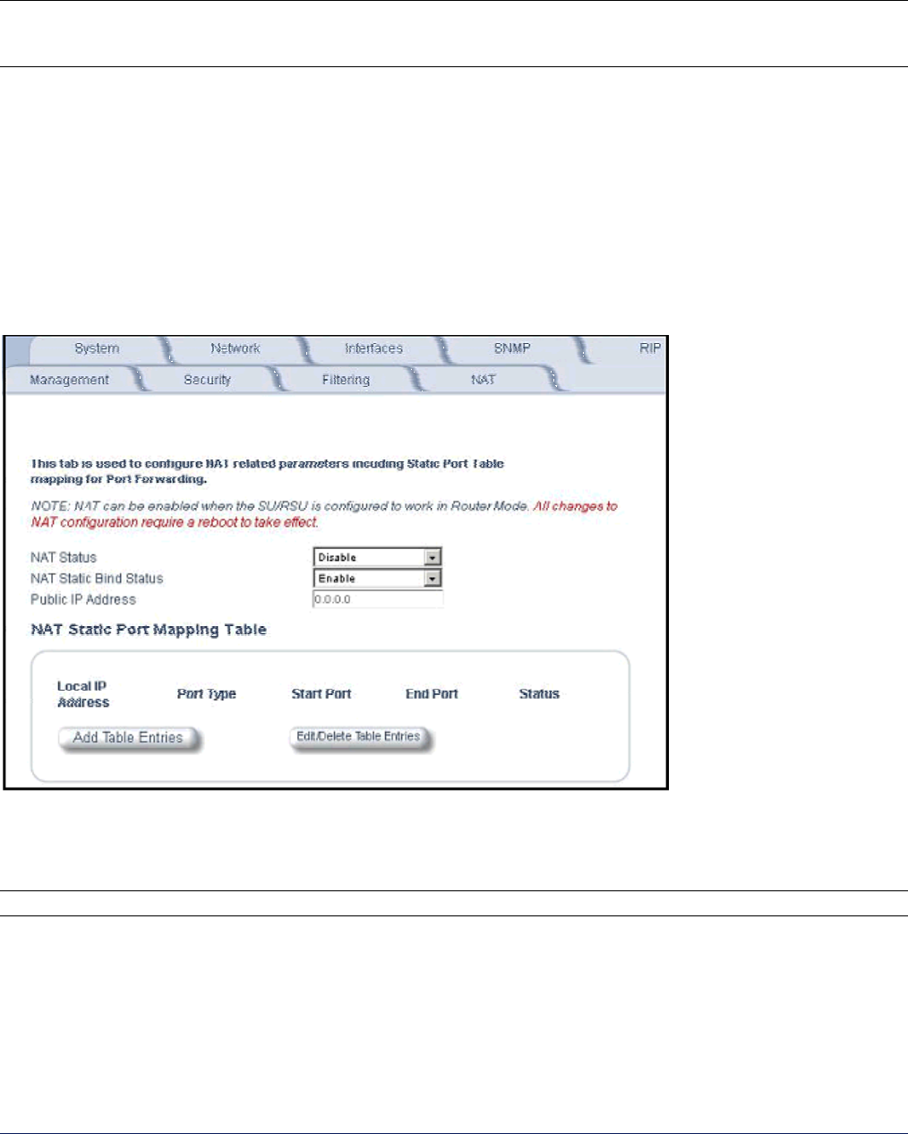
NAT Status
Enables or disables the NAT feature. NAT can be enabled only for SUs in Routing mode.
The default is disabled.
Note: Changes to NAT parameters including the NAT Static Port Mapping Table require a reboot to take effect.
NAT Static Bind Status
Enables or disables the NAT Static Bind status (static mapping) to allow public hosts to access hosts in a
private network. The default is disabled.
Public IP Address
The NAT Public IP address is the wireless interface IP address.
MP.11 and MP.11/a Quick Install Guide
Chapter 5. Web Interface 80
NAT Feature Interactions
When NAT is enabled, the DHCP Relay Agent feature is not supported (DHCP Relay Agent must be disabled
before NAT is enabled) and RIP updates are not sent or received.
DHCP Server Interaction
You can configure a DHCP server to allocate IP addresses to hosts on the Ethernet side of the SU/Base Station
(see DHCP Server).
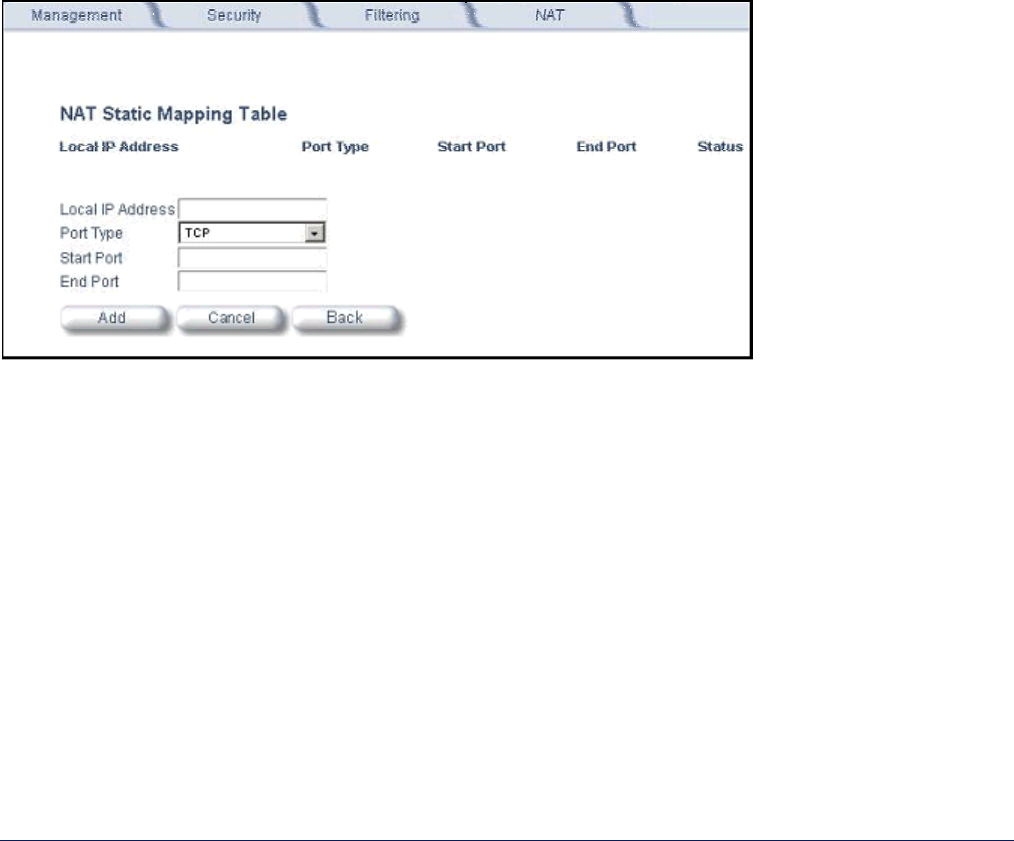
NAT Static Port Mapping Table
Adding entries to the NAT Static Mapping Table lets the configured hosts in a private address realm on the
Ethernet side of the SU access hosts in the public network using Network Address Port Translation (NAPT). Up to
1000 entries can be configured (500 UDP ports and 500 TCP ports).
To add an entry:
1. Click the Add Table Entries button.
2. Enter the Local IP Address of the host on the Ethernet side of the SU.
3. Select the Port Type: TCP, UDP, or Both.
4. Enter the Start Port and End Port
Supported Session Protocols
The NAT feature supports the following session protocols for both inbound and outbound access with the required
support, applications, and limitations given in the following table.
Certain Internet applications require an Application Level Gateway (ALG) to provide the required transparency for
an application running on a host in a private network to connect to its counterpart running on a host in the public
network. An ALG may interact with NAT to set up state information, use NAT state information, modify application
specific payload and perform the tasks necessary to get the application running across address realms.
No more than one server of a particular type is supported within the private network behind the SU.

MP.11 and MP.11/a Quick Install Guide
Chapter 5. Web Interface 81
Supported Session Protocols
Protocol Support Applications Limitations
ICMP ICMP ALG Ping
FTP FTP ALG File transfer
H.323 H.323 ALG Multimedia conferencing
HTTP Port mapping for inbound
connection.
Web browser
TFTP Port mapping for inbound
connection.
File transfer
Telnet Port mapping for inbound
connection.
Remote login
CUSeeMe Port mapping for inbound and
outbound connection.
Video conferencing One user is allowed for video
conferencing
IMAP Port mapping for inbound
connection.
Mail
PNM Port mapping for inbound
connection.
Streaming media with Real
Player
POP3 Port mapping for inbound
connection.
E-mail
SMTP Port mapping for inbound
connection.
E-mail Mails with IP addresses of MTAs or
using IP addresses in place of FQDN
are not supported (requires SMTP
ALG).
RTSP Port mapping for inbound
connection.
Streaming audio/video with
Quick Time and Real
Player
ICQ Port mapping for inbound
connection.
Chat and file transfer Each host using ICQ needs to be
mapped for different ports.
IRC Port mapping for inbound
connection.
Chat and file transfer Each host using IRC needs to be
mapped for different ports.
MSN
Messenger
Port mapping for inbound and
outbound connection.
Conference and Share
files with Net meeting
Only one user is allowed for net
meeting.
Net2Phone Port mapping for inbound and
outbound connection.
Voice communication
IP Multicast Pass Through Multicasting
Stream works Port mapping for inbound
connection.
Streaming video
Quake Port mapping for inbound
connection.
Games When a Quake server is configured
within the private network behind a SU,
the SU cannot provide information
about that server on the public
network.
Also, certain Quake servers do not let
multiple users log in using the same IP
address, in which case only one
Quake user is allowed.
These VPN protocols are supported with their corresponding ALGs: IPsec, PPTP, L2TP.

MP.11 and MP.11/a Quick Install Guide
Chapter 5. Web Interface 82
ADDITIONAL INTERFACE INFORMATION
Dynamic Frequency Selection (Tsunami MP.11a only)
With Tsunami MP.11a units, Dynamic Frequency Selection (DFS) is enabled automatically based upon the
country you select. You can tell DFS is in use because the frequency selection drop-down box on the Interfaces
page is grayed out (click the Configure button and the Interfaces tab); it displays only the DFS-selected
frequency. You cannot select a preferred frequency or band in which to operate. DFS scans all available
frequencies in all available bands to select the operating frequency automatically.
To comply with your country’s regulations, change the DFS selection to specify your country. You can do this by
logging into the unit, clicking the Configure button and selecting the System tab. There is a drop-down box
labeled “Country” with all available countries from which to select. Choose your country, configure the unit as
required, and reboot for the settings to take effect.
Note: Because DFS must scan for radar and interference on multiple channels, you must allow a sufficient
amount of time for the units to start up. This is considerably longer than when the unit is not using DFS.
Startup time is usually within two to three minutes if no radar is detected. If radar is detected, the unit
may reboot multiple times before it becomes fully operational and can take much longer to start. This is
expected behavior.
DFS Requirement
Dynamic Frequency Selection (DFS) is required in FCC and ETSI countries; it is enabled automatically when you
select a country with a regulatory domain that requires DFS. DFS is required for two purposes.
1. Radar avoidance both at startup and while operational. To meet these requirements, the Tsunami MP.11a
BSU scans available frequencies at startup for the presence of a radar signal on all available frequencies; it
does not use any frequency in which radar signals are detected. Once fully operational on a frequency, the
BSU actively monitors the occupied frequency for radar interference. If radar interference is detected, the
BSU logs a message and reboots to find a new frequency free of interference.
Understand that radar detection is performed only by the BSU and not by the SU. When an SU is set to a
country in which DFS is used, it scans all available channels upon startup looking for a BSU that best
matches its connection criteria (such as Base Station System Name, Network Name, and Shared Secret).
The SU connects to the BSU automatically on whatever frequency the BSU has selected. Because of this
procedure, it is best to set up the BSU and have it fully operational before installing the SU, although this is
not required. If a BSU reboots because of radar interference, the SU loses its WORP link. The SU waits 30
seconds, and if it finds that the WORP link is down, it rescans the available frequencies for an active BSU.
2. Guarantee the efficient use of available frequencies by all devices in a certain area. To meet this
requirement, the BSU scans each available frequency upon startup and selects a frequency based upon the
least amount of noise and interference detected. This lets multiple devices operate in the same area with
limited interference. This procedure is done only at startup; if another non-radar device comes up on the
same frequency, the BSU does not detect this or reboot because of it. It is expected that other devices using
these frequencies also are in compliance with country regulations, so this should not happen.

MP.11 and MP.11/a Quick Install Guide
Chapter 5. Web Interface 83
Wireless Outdoor Router Protocol
The Wireless Outdoor Router Protocol (WORP) is a polling algorithm designed for wireless outdoor networks.
WORP takes care of the performance degradation incurred by the so-called “hidden-node” problem, which can
occur when standards-based 802.11b wireless LAN technology is used for outdoor building-to-building
connectivity. In this situation, when multiple radios send an RTS, if another radio is transmitting, it corrupts all
data being sent, degrading overall performance. The WORP polling algorithm ensures that these collisions
cannot occur, which increases the performance of the overall network significantly.
WORP dynamically adapts to the number of SUs that are active on the network and the amount of data they have
queued to send.
Satellite Density
The Satellite Density setting is a valuable feature for achieving maximum bandwidth in a wireless network. It
influences the receive sensitivity of the radio interface. This feature improves operation in environments with a
high noise level. Reducing the sensitivity of the radio enables unwanted “noise” to be filtered out. (It disappears
under the threshold.)
You can configure the Satellite Density to be Large, Medium, Small, Mini, or Micro. The default value for this
setting is Large. The smaller settings are appropriate for high noise environments; a setting of Large would be for
a low noise environment.
A long distance link may have difficulty maintaining a connection with a small density setting because the wanted
signal can disappear under the threshold. Consider both noise level and distance between the peers in a link
when configuring this setting. The threshold should be chosen higher than the noise level, but sufficiently below
the signal level. A safe value is 10 dB below the present signal strength.
If the Signal-to-Noise Ratio (SNR) is not sufficient, you may need to set a lower data rate or use antennas with
higher gain to increase the margin between wanted and unwanted signals. In a point-to-multipoint configuration,
the Base Station should have a density setting suitable for all of its registered SUs, especially the ones with the
lowest signal levels (longest links).
Take care when configuring a remote interface; check the available signal level first, using Remote Link Test.
Warning!
When the remote interface accidentally is set at too small a value and communication is lost, it cannot be
reconfigured remotely and a local action is required to bring the communication back. Therefore, the best place to
experiment with the level is at the unit that can be managed without going through the link; if the link is lost, the
setting can be adjusted to the correct level to bring the link back.
To set the Satellite Density, click the Configure button, then the Interfaces tab and the Wireless sub-tab.
Make your density selection from the drop-down menu. This setting requires a reboot of the unit.
Sensitivity threshold settings related to the density settings for the MP.11a (802.11a) are:
Satellite Density Large Medium Small Mini Micro
Receive Sensitivity Threshold -95 dBm -86 dBm -78 dBm -70 dBm -62 dBm
Defer Threshold -62 dBm -62 dBm -52 dBm -42 dBm -36 dBm
Sensitivity threshold settings related to the density settings for the MP.11 (802.11b) are:
Satellite Density Large Medium Small Mini Micro
Receive Sensitivity Threshold -99 dBm -90 dBm -85 dBm -72 dBm -66 dBm
MP.11 and MP.11/a Quick Install Guide
Chapter 5. Web Interface 84
MONITOR
Use this section of the interface to obtain detailed information about the settings and performance of the MP.11/a.
There are 12 tabs in the Monitor section. The Radius tab is available on Base Stations only.
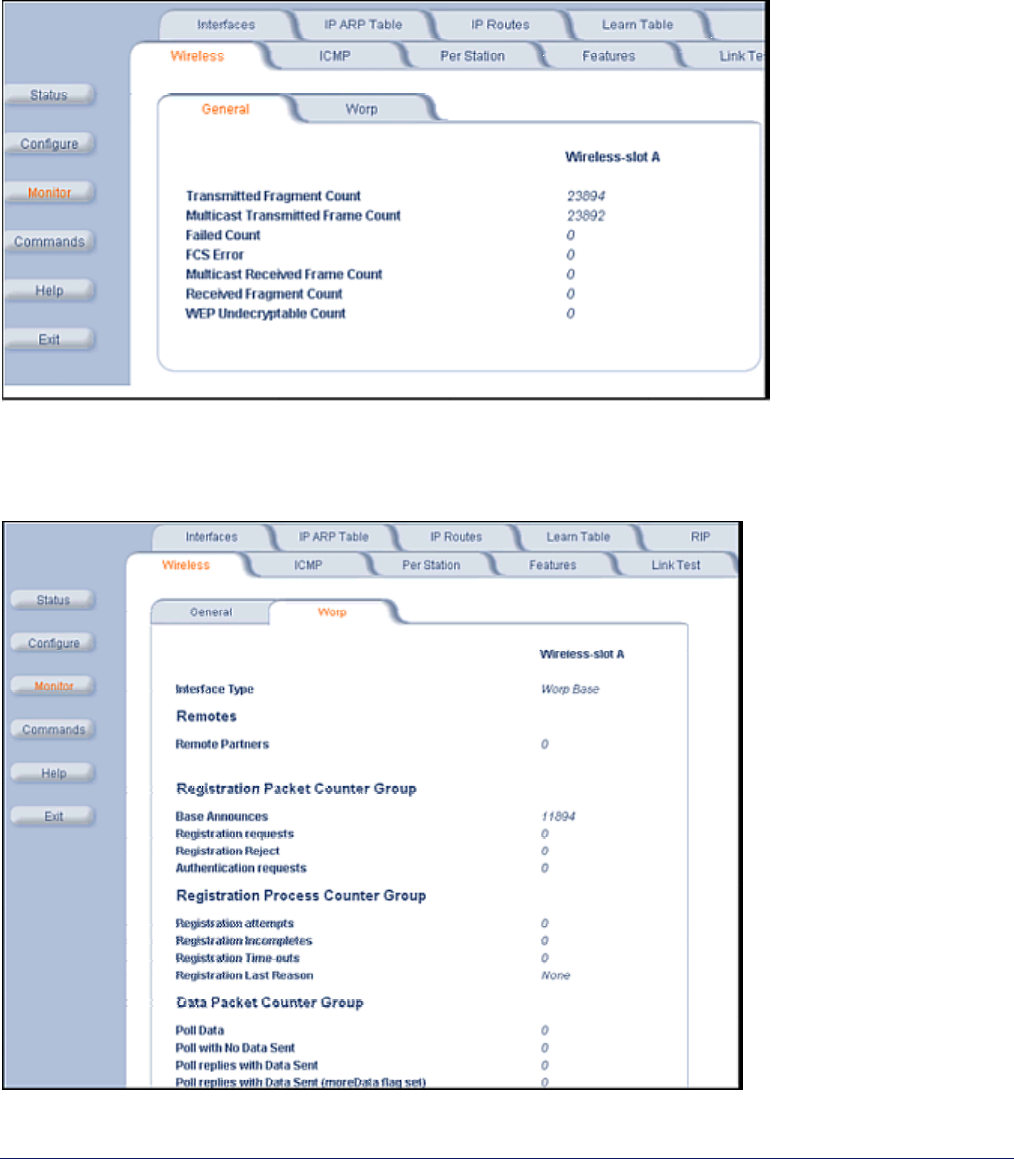
1) Wireless
General
Click the Monitor button and the General tab to monitor the general performance of the wireless interface.
WORP
Click the Monitor button, the Wireless tab, and the WORP tab to monitor the performance of the WORP Base or
WORP SU interfaces.
MP.11 and MP.11/a Quick Install Guide
Chapter 5. Web Interface 85
The Registration Last Reason field indicates either a successful registration (a value of 1) or it indicates the
reason why the last registration failed.
Possible values for the Registration Last Reason field are as follows:
1 = Successful registration
2 = Maximum number of SUs reached
3 = Authentication failure
4 = Roaming
5 = No response from SU within the Registration Timeout Period
6 = Low Signal Quality
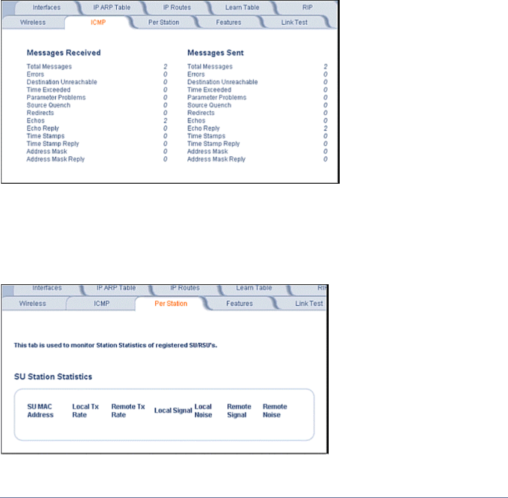
2) ICMP
Click the Monitor button and the ICMP tab to view the number of ICMP messages send and received by the
MP.11/a. It includes ping, route, and host unreachable messages.
3) Per Station
Click the Monitor button and the Per Station tab to view Station Statistics. On the SU, the “Per Station” page
shows statistics of the BSU to which the SU is registered. On the BSU, it shows statistics of all the SU’s
connected to the BSU.
The page’s statistics refresh every 4 seconds.
MP.11 and MP.11/a Quick Install Guide
Chapter 5. Web Interface 86
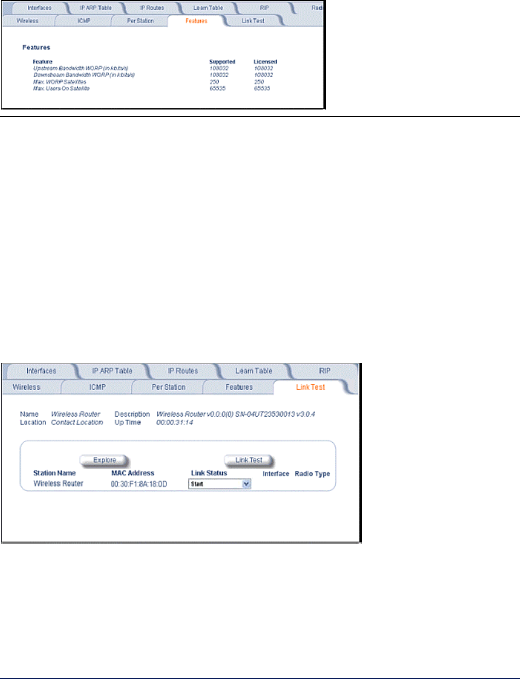
4) Features
Click the Monitor button and the Features tab to view the following information:
Note: A Base Station shows how many WORP SUs it can support; the Subscriber Unit and Residential
Subscriber Unit shows how many Ethernet hosts they support on their Ethernet port as the “Max Users on
Satellite” parameter.
5) Link Test
Click the Monitor button and the Link Test tab to find out which wireless stations are in range and to check their
link quality.
Note: Link Test requires Internet Explorer version 6.0 or later. Earlier versions do not support Link Test.
Link Test for the MP.11a reports a single Receive Signal Strength Indicator (RSSI) value; the higher the number,
the better the signal.
• Explore from a BSU displays all its registered SUs.
• Explore from an SU or RSU displays only the BSU with which it is registered.
All stations displayed after “Explore” come up “Disabled.” Select a station by changing Disabled to Start and
click the Link Test button. You can change multiple stations to Start, but only the last station in the list is
displayed as the remote partner when you click the Link Test button. See the following figure:
For the MP.11a ( 802.11a), the Link Test provides the following information. The MP.11 ( 802.11b) Link Test also
displays information about noise.)
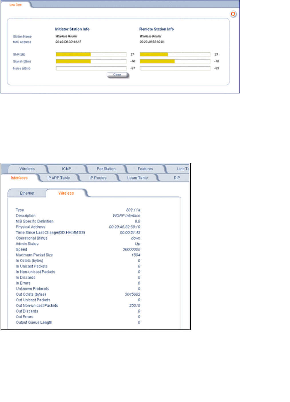
MP.11 and MP.11/a Quick Install Guide
Chapter 5. Web Interface 87
Link Test stops when you close the Link Test page.
6) Interfaces
Click the Monitor button and the Interfaces tab to view detailed information about the IP-layer performance of the
MP.11/a interfaces. There are two sub-tabs: Wireless and Ethernet.
The following figure shows the Wireless interface; the same information is provided for the Ethernet interface on
the Ethernet sub-tab.
MP.11 and MP.11/a Quick Install Guide
Chapter 5. Web Interface 88
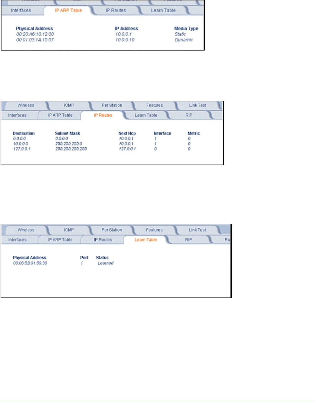
7) IP ARP Table
Click the Monitor button and the IP ARP Table tab to view the mapping of the IP and MAC addresses of all
radios registered at the MP.11/a. This information is based upon the Address Resolution Protocol (ARP).
8) IP Routes
Click the Monitor button and the IP Routes tab to view all active IP routes of the MP.11/a. These can be either
static or dynamic (obtained through RIP). This tab is available only in Routing mode, and you can add routes
only when in Routing mode.
9) Learn Table
Click the Monitor button and the Learn Table tab to view all MAC addresses the MP.11/a has detected on an
interface. The Learn Table displays information relating to network bridging. It reports the MAC address for each
node that the device has learned is on the network and the interface on which the node was detected. There can
be up to 10,000 entries in the Learn Table. This tab is only available in Bridge mode.
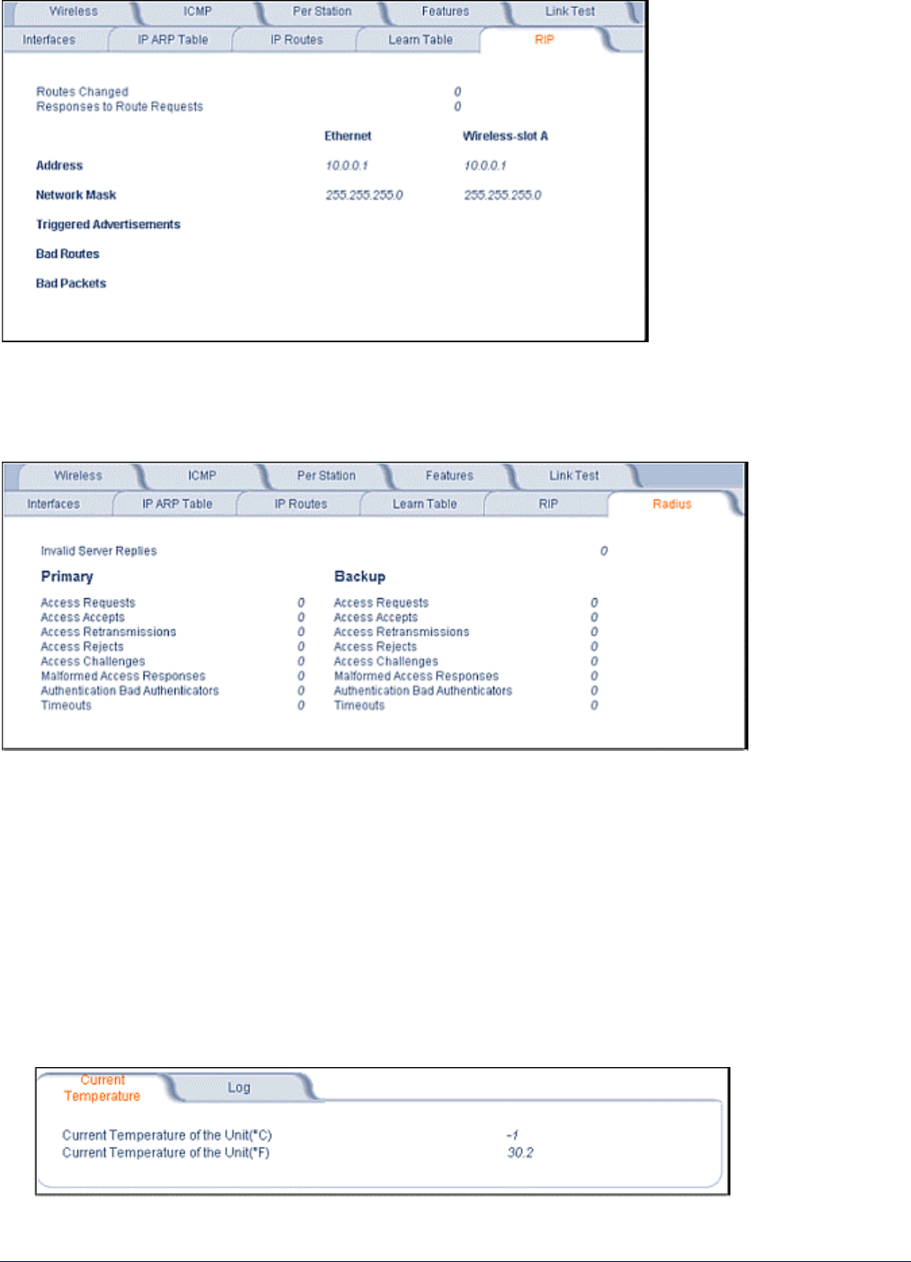
10) RIP
Click the Monitor button and the RIP tab to view Routing Internet Protocol data for the Ethernet and Wireless
interfaces.
MP.11 and MP.11/a Quick Install Guide
Chapter 5. Web Interface 89
11) Radius
Click the Monitor button and the Radius tab to view information about the traffic exchanged with a RADIUS
server.
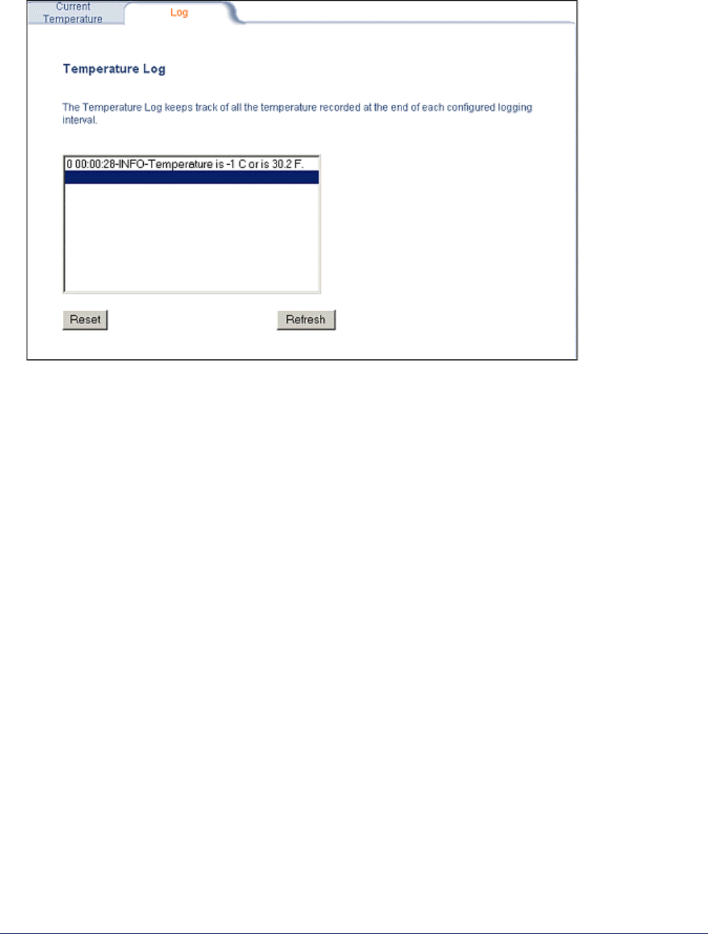
12) Temperature Log (BSU Only)
The feature for reporting and logging internal unit temperature observes and reports the internal temperature of
the unit. Temperature is logged and an SNMP trap sent when the temperature crosses the limit of -30ºC to 60ºC.
You can select a recording interval from one to sixty minutes, in 5-minute increments on the Configure: System
tab. A log file holds the recorded data. The log can hold at least 576 entries (two days with the refresh time of 5
minutes). For further analysis, the log can be exported to a text file with a new line feed as a line separator.
The Temperature Log contains two sub-tabs.
• The Current Temperature tab indicates the unit’s current temperature. The current temperature value is
refreshed every 4 seconds.
MP.11 and MP.11/a Quick Install Guide
Chapter 5. Web Interface 90
• The Log tab keeps track of the temperature recorded at the end of each configured logging interval. You can
reset or refresh the log using the Reset and Refresh buttons.
MP.11 and MP.11/a Quick Install Guide
Chapter 5. Web Interface 91
COMMANDS
This section describes the commands that you can perform with the Web Interface. The following tabs are in the
Commands section: Download, Upload, Downgrade, Reboot, Reset, and Help Link.
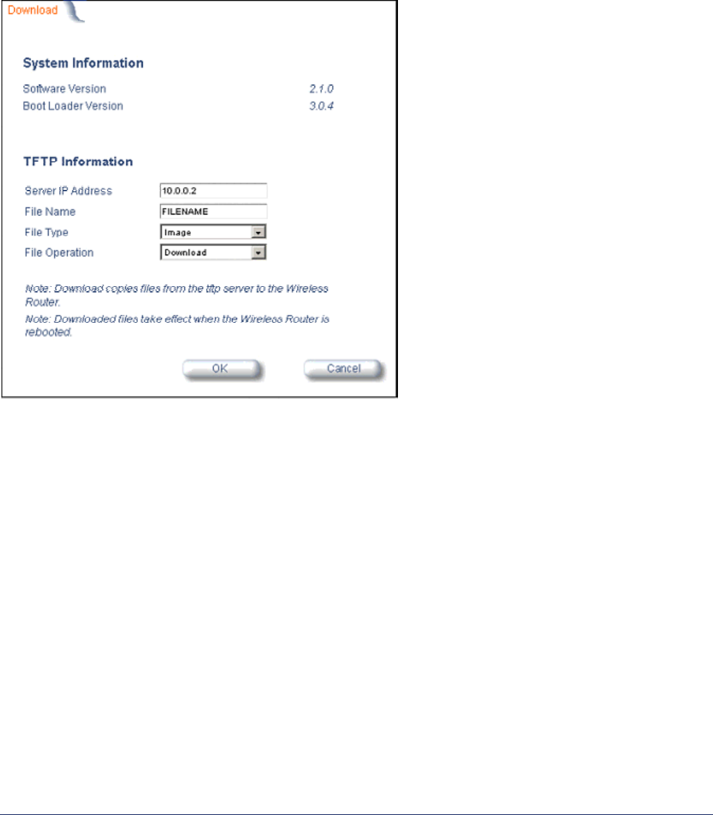
1) Download
Click the Commands button and the Download tab to download image, configuration, and license files to the
MP.11/a.
Server IP address
Enter the TFTP Server IP address. (Double-click the TFTP server icon on your desktop and locate the IP
address assigned to the TFTP server.)
File Name
Enter the name of the file to be downloaded.
File Type
Config, image, BspBl, or license.
File Operation
Download or Download and Reboot.
MP.11 and MP.11/a Quick Install Guide
Chapter 5. Web Interface 92
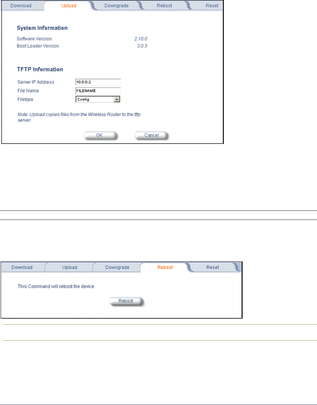
2) Upload
Click the Commands button and the Upload tab to upload a configuration file from the MP.11/a. Enter Server IP
Address, File Name, select a Filetype, and click OK.
Filetype can be configured as Templog, Eventlog, or Config.
3) Downgrade
Click the Commands button and the Downgrade tab to downgrade to a previous MP.11/a release. Downgrade
currently is supported only to release 2.0.1.
Once you enter this command, the device is downgraded to release version 2.0.1 and is automatically rebooted.
Note: The Downgrade command applies only to the outdoor MP.11/a.
4) Reboot
Click the Commands button and the Reboot tab to restart the embedded software of the MP.11/a. Configuration
changes are saved and the MP.11/a is reset.
CAUTION: Rebooting the unit causes all users currently connected to lose their connection to the
network until the MP.11/a has completed the restart process and resumed operation.
MP.11 and MP.11/a Quick Install Guide
Chapter 5. Web Interface 93
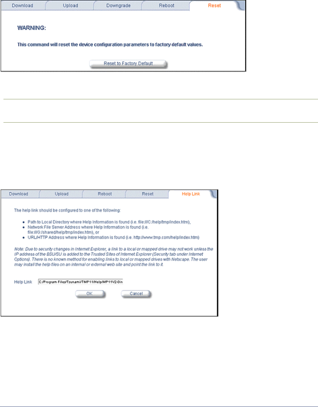
5) Reset
Click the Commands button and the Reset tab to restore the configuration of the MP.11/a to the factory default
values.
You can also reset the MP.11/a from the RESET button located on the side of the unit. Because this resets the
MP.11/a’s current IP address, a new IP address must be assigned.
CAUTION: Resetting the MP.11/a to its factory default configuration permanently overwrites all
changes made to the unit. The MP.11/a reboots automatically after this command has been
issued.
6) Help Link
Click the Commands button and the Help Link tab to set the location of the help files of the Web Interface. Upon
installation, the help files are installed in the C:\Program Files\Proxim\Tsunami MP11\Help\ folder.
If you want to place these files on a shared drive, copy the Help folder to the new location and specify the new
path in the Help Link box.

MP.11 and MP.11a Installation and Management
Chapter 2. Installation 94
Chapter 6. Command Line Interface
The Command Line Interface (CLI) provides a text-based interface with which you can configure and manage the
MP.11/a using commands. You can enter these commands or submit them in the form of a script to allow batch
processing. Accessing the CLI is discussed in “Command Line Interface Overview” on page 29.
Administrators use the CLI to control MP.11/a operation and monitor network statistics. The MP.11/a supports
two types of CLI—the Boot Loader CLI and the normal CLI. The Boot Loader CLI provides a limited command set
and is used when the current Image is bad or missing.
BOOT LOADER CLI
The Boot Loader CLI is a minimal subset of the normal CLI used to perform initial configuration of the MP.11/a.
The Boot Loader is started when the MP.11/a is switched on or reset, and is responsible for starting the
embedded software. The Boot Loader CLI is available when the MP.11/a embedded software is not running.
This interface is accessible only through the serial interface if the MP.11/a does not contain a software image or a
download image command over TFTP has failed.
The Boot Loader CLI lets you configure the initial setup parameters as well as download a software image to the
device.
The following commands are supported by the Boot Loader CLI:
• Set for configuration of initial device parameters
• Show to view the device’s configuration parameters
• Help to provide additional information about all commands supported by the Boot Loader CLI
• Reboot to reboot the device
The parameters supported by the Boot Loader CLI for viewing and modifying are:
• System name
• IP address assignment type
• IP address
• IP mask
• Gateway IP address
• TFTP Server IP address
• Image Filename (including the file extension)

MP.11 and MP.11/a Quick Install Guide
Chapter 6. Command Line Interface 95
CLI TERMINOLOGY
Configuration Files
Database files containing the current configuration information. Configuration items include the IP address
and other network-specific values. Configuration files can be downloaded to the MP.11/a or uploaded for
backup or troubleshooting.
Download versus Upload
Downloads transfer files to the MP.11/a; uploads transfer files from the MP.11/a. The TFTP server performs
file transfers in both directions.
Group
A logical collection of network parameter information. For example, the System Group is comprised of
several related parameters. Groups also can contain tables. All items for a given group can be displayed
with a show <Group> CLI command.
Image File
The MP.11/a software executed from RAM. To update an MP.11/a, you typically download a new image file.
Parameter
A fundamental network value that can be displayed and may be changeable. For example, the MP.11/a must
have a unique IP address and the wireless interface must be assigned an SSID. Change parameters with the
CLI set command and view them with the CLI show command.
Table
Tables hold parameters for several related items. For example, you can add several potential managers to
the SNMP table. All items for a given table can be displayed with a show <table> CLI command.
TFTP
Refers to the TFTP Server, used for file transfers.

MP.11 and MP.11/a Quick Install Guide
Chapter 6. Command Line Interface 96
NAVIGATION AND SPECIAL KEYS
The CLI supports these navigation and special key functions to move the cursor along the prompt line:
Key Combination Description
Delete or Backspace Delete previous character
Ctrl–A Move cursor to beginning of line
Ctrl–E Move cursor to end of line
Ctrl–F Move cursor forward one character
Ctrl–B Move cursor back one character
Ctrl–D Delete the character the cursor is on
Ctrl–U Delete all text to the left of the cursor
Ctrl–P Go to the previous line in the history buffer
Ctrl–N Go to the next line in the history buffer
Tab Complete the command line
? List available commands
COMMANDS
The commands listed in the following table are described in more detail in the following subsections.
Command Action
? Lists commands
done Disconnects and closes the current CLI session
download Transfer files from the TFTP server to the MP.11/a
downgrade Downgrade to a previous MP.11/a release
exit Disconnects and closes the current CLI session
help View command specifics or control-key sequences you can use to navigate
history Lists commands previously entered
log Manage the event log file maintained by the MP.11a
passwd Change the password used to access the CLI
quit Disconnects and closes the current CLI session
reboot Signal the MP.11/a to reboot after a specified number of seconds
save Save the current MP.11/a configuration to flash memory
search Display the parameter entries in a specified table
set Change parameter values
show View parameter and statistical values
templog View the temperature log
upload Transfer files from the MP.11/a to the TFTP server
Also see “Show and Set Parameters” on page 103 and “Table Parameters” on page 114.

MP.11 and MP.11/a Quick Install Guide
Chapter 6. Command Line Interface 97
? (Question Mark)
You can show CLI help by entering help at the command prompt. The CLI also provides context-specific help. For
help in a specific situation, enter ?.
You can get help as follows:
display the
command list
?
s?
display commands
that start with
specified letters The more letters you enter, the fewer the results returned.
Enter one or more letters, then ? with no space between letters and ?
download ?
display parameters
for set and show
commands Lets you see every possible parameter for the set or show commands
Enter the command, a space, then ?
download ?
download 169.254.128.133 ?
download 169.254.128.133 image.bin ?
download 169.254.128.133 image.bin image
display prompts for
successive
parameters
Enter the command, a space, and then ?. Then, when the parameter prompt
appears, enter the parameter value. The parameter is changed and a new
CLI line is echoed with the new value.
After entering one parameter you can add another ? to the new CLI line to
see the next parameter prompt, and so on until you have entered all the
required parameters.
Note that the Boot Loader CLI does not have command help.
Done Command
The quit, done, and exit commands are used to disconnect and close the current CLI session.
Downgrade Command
The downgrade command lets you downgrade to a previous MP.11/a release. Downgrade currently is supported
only to release 2.0.1 (rel201). Enter Rel201 or rel201 as the Release Number.
Once you enter this command, the device is downgraded to release version 2.0.1 and is automatically rebooted.
Note: The Downgrade command applies only to the outdoor MP.11/a.
downgrade <TFTPIPAddress> <TFTP filename> <filetype (image)> <Release Number>
The filetype must be image.

MP.11 and MP.11/a Quick Install Guide
Chapter 6. Command Line Interface 98
Download Command
The download command is used to transfer files from the TFTP server to the MP.11/a. Executing download in
combination with the asterisk character (*) makes use of the previously set TFTP parameters. Executing
download without parameters displays command help and usage information.
To transfer a file from the TFTP server to the MP.11/a:
download <tftpserveraddress> <path and filename> <filetype>
where <filetype> can be one of these four values:
config - Configuration file, the current settings of the MP.11/a
image - Image file, embedded software for the MP.11/a
bootloader - Boot software
license - License file
To issue repeated operations, use the asterisk (*) character in place of the options: download *
Previously used optional values for the download command is stored in TFTP parameters that you can view and
change. See the TFTP parameter table for details.
Exit Command
The quit, done, and exit commands are used to disconnect and close the current CLI session.
Help Command
Use the help command to view the specifics of certain commands or to view control-key sequences you can use
to navigate the command line.
To display how to navigate the command line using special keys:
help
The following represents part of the displayed output:
Special keys supported:
Arrow Keys
DEL, BS .... delete previous character
Ctrl-A .... go to beginning of line
Ctrl-E .... go to end of line
Ctrl-F .... go forward one character
Ctrl-B .... go backward one character
Ctrl-D .... delete current character
Ctrl-U, X . .. delete to beginning of line
Ctrl-K .... delete to end of line
Ctrl-W ..... delete previous word
Ctrl-T ..... transpose previous character
Ctrl-P .... go to previous line in history buffer
Ctrl-N .... go to next line in history buffer
Tab .... will attempt command completion
? .... will provide command listing
For a description and example of the specified command, enter:
help <command name> or <command name> help

MP.11 and MP.11/a Quick Install Guide
Chapter 6. Command Line Interface 99
History Command
Use the history command to show this list of commands. Commands entered in the current session are stored
in a Command History Buffer. To avoid re-entering long command statements, use the keyboard up arrow (↑) and
down arrow ( ↓) keys to recall previous statements from the Command History Buffer. When the desired
statement reappears, press the Enter key to execute, or you can edit the statement before executing it.
history
Log Command
Use the log command to manage the event log file maintained by the MP.11/a.
To append a user-specified string to the event log, enter:
log addstring <anyString>
To append a user-specified string multiple times to the event log, enter:
log addmany <numMsgs> <anyString>
To reset the event log, enter the following. Note that this generates an event log message stating that the log has
been reset intentionally.
log reset
To display the contents of the entire event log, enter:
log dump
To display the current number of log entries:
log count
To display the log entry corresponding to the specified number, enter:
log display <msgNum>
The first log entry is numbered 0. If no parameter is supplied, the entire event log is displayed.
Passwd Command
Use the passwd command to change the password used to access the CLI.
passwd <old password> <new password> <new password>
Enter the new password twice to ensure no mistake was made when specifying the new password. If you forget
the CLI password, there is no way to retrieve it from the MP.11/a and the CLI cannot be accessed. In this case,
the MP.11/a must be reset to factory defaults. The default password for the CLI is public.
Quit Command
The quit, done, and exit commands are used to disconnect and close the current CLI session.
Reboot Command
Use the reboot command to signal the MP.11/a to reboot after a specified number of seconds.
reboot <number of seconds>
The <number of seconds> parameter must be positive. Specify a value of 0 (zero) for an immediate reboot.

MP.11 and MP.11/a Quick Install Guide
Chapter 6. Command Line Interface 100
Save Command
Use the save command to save the current configuration of the MP.11/a to flash memory.
save config
Search Command
Use the search command to list the parameters supported by the specified table. This list corresponds to the
table information displayed in the HTTP interface.
search <table name>
See “Table Parameters” on page 114 for details.
Set Command
The set command lets you change parameter values. You can set a single parameter value, or you can set a
group of parameters or a table with parameters. If a parameter requires more than one value, the values must be
separated by spaces.
For example, to set the MP.11/a IP address parameter:
set ipaddrtype static
set ipaddr 1 ipaddress 10.0.0.12
Some parameter values change only when the MP.11/a is rebooted. In these cases, the CLI warns you that a
reboot is required for the change to take effect.
See “Show and Set Parameters” on page 103 for a list of parameters that can be used with the set command.
Show Command
The show command lets you view parameter and statistical values. You can view a single parameter, a group of
parameters, or a table with parameters. (A table consists of rows with similar parameters.)
To see a definition and syntax example, enter only show. To see a list of available parameters, enter a question
mark after show (example show ?).
To view the current values of all system parameters: show system
See “Show and Set Parameters” on page 103 for a list of parameters that can be used with the show command.
Templog Command
The templog command is used to display the temperature log for the radio. The temperature log is a file in flash
memory that holds the temperature data.
templog dump Displays the temperature log
templog reset Resets the temperature log
upload <target ip> <filename> templog Export the log to a text file for further analysis
• Maximum number of entries in the log is 576 (2 days with the refresh time of 5 minutes).
• The log is exportable to a text file for further analysis.
• The range of the internal unit temperature (IUT) is from -30° C to 60° C
• The range of the recording interval of IUT is from 1 to 60 minutes, configurable in 5-minute increments (1, 5,
10, 15, 20, 25, 30, 35, 40, 45, 50, 55, 60)

MP.11 and MP.11/a Quick Install Guide
Chapter 6. Command Line Interface 101
Note: For the outdoor MP.11/a, if a walk operation is performed on the MIB variable oriTempLogTableEntry
using SNMP V2 default settings, log entries are repeated about 10 times (as the maximum repetitions in
SNMP V2 is 10). Set the maximum repetitions value to 1 or uncheck the Use Get Bulk option for all
entries to be displayed without any repetitions in the MIB browser.
Upload Command
The upload command is used to transfer files from the MP.11/a to the TFTP server.
To upload a file from the MP.11/a to the TFTP server:
upload <tftpserveraddress> <path and filename> <filetype>
where <filetype> can be one of these four values:
config - Configuration file, the current settings of the MP.11/a
templog – Temperature log
eventlog – Event log
To issue repeated operations, use the asterisk (*) character in place of the options:
upload *
Previously used optional values for the upload command is stored in TFTP parameters that you can view and
change. See the TFTP parameter table for details.

MP.11 and MP.11/a Quick Install Guide
Chapter 6. Command Line Interface 102
CLI BASIC MANAGEMENT COMMANDS
You may want to set up the following basic configuration parameters immediately when you receive the MP.11/a.
Task Commands
Set System Name, Location, and
Contact information
show system
set sysname <name>
set sysloc <location>
set sysctname <contact name>
set sysctemail <contact email>
set sysctphone <contact phone>
set syscountrycode <country code>
Shows the type of hardware being used show syshwtype hardwaretype
Set IP address for the MP.11/a set ipaddrtype <static | dynamic>
set ipaddr 1 ipaddress <ip address>
set ipaddr 1 ipsubmask <subnet mask>
For example:
set ipaddr 1 ipaddress <ip address> ipsubmask <subnet mask>
Set default gateway set ipgw <gateway address>
Configure Wireless Interface set wif 3 channel 10
set wif 3 netname <network name>
For more Wireless Interface parameters, see “Wireless Interface Parameters” on
page 112
Configure Ethernet Interface show ethernet
set Ethernet 1 etherspeed <autospeedauto | autospeedhalf |
100auto | 100full | 100 half | 10full | 10half>
Set Encryption for the Wireless
interface
show wifsec
set wifsec 3 encryptoption <wep|aes|none>
set wifsec 3 encryptkey1 <key 1>
set wifsec 3 encryptallowdeny <enable | disable>
Set Telnet Password show telnet
set telifbitmask <0-15>
set tellogintout <login timeout>
set telport <port number>
set telsessiontout <inactivity timeout>
Set Web Interface Password show http
set httpifbitmask <0-15>
set httppasswd <password>
set httpport <port number>
Set SNMP Password show snmp (displays the read password, read/write password,
IP Access Table entries, and SNMP Interface Bitmask)
set snmprpasswd <read password>
set snmprwpasswd <read/write password>
set snmpifbitmask <0-15>
Download an MP.11/a configuration file
from your TFTP server
Download <ipaddr> <tftpfilename> <tftpfiletype>
show tftp (to ensure the entries are correct)
download *
reboot 0
Backup your MP.11/a configuration file upload <ipaddr> <tftpfilename> <tftpfilename>
show tftp (to ensure the entries are correct)
upload *
Reboot reboot [<number of seconds>]
Reset to Factory Defaults set sysresettodefaults 1

MP.11 and MP.11/a Quick Install Guide
Chapter 6. Command Line Interface 103
SHOW AND SET PARAMETERS
The following table details the non-table parameters available to be viewed and set within the MP.11/a CLI.
R = Read-only W = Write-only RW = Read-Write
Antenna Alignment Display Parameters
Antenna Alignment Display (AAD) provides a measurement of signal quality in an easy-to-interpret manner (a
numeric printed signal value at the CLI and serial ports). The SNR is displayed numerically on the CLI or serial
port by two decimal characters representing a number from 00 to 99. On the serial port, AAD is enabled by default
after booting.
To start the display, you must enable AAD and a WORP link must be established between the Base Station and
SU.
aad RW
set aad enable local
Enables display of the local SNR. Local SNR is the SNR measured by the receiver at the near end.
set aad enable remote
Enables display of the remote SNR. Remote SNR is the SNR as measured by the receiver at the far
end.
set aad enable average
Enables display of the average SNR. The average SNR is the average of the local and remote SNR.
set aad disable
Disables Antenna Alignment Display. Also, ctrl-c disables AAD.
AAD is automatically disabled 30 minutes after it is enabled to remove the load of extra messages on
the wireless interface. The default telnet timeout is 900 seconds (15 minutes). In this case, AAD auto
stops in 15 minutes. If AAD is required to run for the full 30 minutes, change the default telnet timeout
to a value greater than 30 minutes (greater than 1800 seconds). This restriction is for telnet
connections only and not for the serial interface. The serial interface never times out.
Broadcast Filtering Parameters
broadcastflttbl RW
Broadcast Filter Table
index R
Index
protoname R
Protocol name
direction RW
Filtering Direction [1=ethernet to wireless, 2=wireless to ethernet, 3=both]
status RW
Status of table entry [1=enable, 2=disable]
DHCP Relay Parameters
dhcprelay R
DHCP Relay Group
dhcprelaystatus RW
DHCP Relay Status [1=enable, 2=disable]
dhcprelayipaddr RW
DHCP Server IP address
dhcprelaycmt RW
Comment

MP.11 and MP.11/a Quick Install Guide
Chapter 6. Command Line Interface 104
DHCP Server Parameters
dhcp R
DHCP Server Group
dhcpstatus RW
DHCP Server Status. [1=enable, 2=disable].
dhcpgw RW
DHCP Server Gateway IP address.
dhcpsubnetmask R
DHCP Server Gateway Subnet Mask.
dhcppridnsipaddr RW
DHCP Server Primary DNS IP address.
dhcpsecdnsipaddr RW
DHCP Server Secondary DNS IP address.
dhcpippooltbl RW
DHCP Server IP Pool Table
index R
Index
startipaddr RW
Start IP address in the form xxx.xxx.xxx.xxx.
endipaddr RW
End IP address in the form xxx.xxx.xxx.xxx.
defaultleasetime RW
Default lease time. 3600-86400.
maxleasetime RW
Maximum lease time. 3600-86400.
comment RW
Comment. 1-255 characters.
status RW
Status of table entry. [1=enable, 2=disable, 3 = delete, 4 = create]
Ethernet Parameters
ethernet RW
Ethernet Configuration Table
index R
Index
etherspeed RW
Speed [1=10M Half Duplex
2=10M Full Duplex
3=10M Auto Duplex
4=100M Half Duplex,
5=100M Full Duplex
6=Auto Speed Half Duplex 7=Auto Speed Auto Duplex]
Ethernet Filtering Parameters
etherflt R
Ethernet Filtering Group
etherflttbl RW
Ethernet Filter Table
index R
Index
proto RW
Ethernet Filtering Protocol
cmt RW
Comment {1-255 characters]
status RW
Status of table entry {1=enable, 2=disable]
etherfltoptype RW
Operation type [1=allow, 2=deny]
etherfltifbitmask RW
Interface bitmask
Feature Parameter
featuretbl R
Table of supported features on current image file
HTTP (WEB BROWSER) Parameters
http R
HTTP Group
httpport RW
HTTP port
httppasswd W
HTTP password
httpifbitmask RW
HTTP interface bitmask
httphelplink RW
Help link

MP.11 and MP.11/a Quick Install Guide
Chapter 6. Command Line Interface 105
Internal Unit Temperature Parameters
internalunittemp R
Internal unit temperature
iutlogginginterval RW
IUT logging interval
Intra-Cell Blocking Parameters
Limitations:
• Telnet Server supports only 32 arguments; therefore, any command comprising greater than 32 arguments
results in an error.
• When “sh intra” is used to show commands relating to Intra-cell blocking, some of the commands displayed
are too long to be shown with clear boundaries when all the commands are shown on the CLI.
intracellblockingstatus RW
Enable or disable Intra-Cell blocking.
intracellgrptbl RW
Intra-Cell Group Table. Defines the filter groups.
index R
Index
grpname RW
Name of the Intra-Cell group, 1-255 characters.
grpstatus RW
Status of table entry [1=enable, 2=disable, 3=delete].
intracellmactbl RW
Intra-Cell MAC Address Table. Enables or disables a MAC address and
assigns it to a specific filter group.
index R
Index
mac RW
MAC Address of the SU.
grpid1 (to grpid16) RW Status of group entry [1=active, 2=inactive, 3=delete].
macstatus RW
Status of table entry [1=enable, 2=disable, 3=delete]
Default is enable.
intracellsecuritygwstatus RW
Enable or disable packet forwarding to an external Security Gateway.
intracellsecuritygwmac RW
MAC address of the Security Gateway.
Inventory Management Parameters
sysinvmgmt R
Inventory Management Group
sysinvmgmtcmpiftbl R
Inventory Interface Table
sysinvmgmtcmptbl R
Inventory Component Table
IP ARP Parameters
parp R
Proxy ARP Group
parpstatus RW
Proxy ARP status [1=enable, 2=disable]
IP ARP Filtering Parameters
IPARP R
IP ARP Group
iparpfltipaddr RW
IP address
iparpfltstatus RW
Status [1=enable, 2=disable]
iparpfltsubmask RW
Subnet mask

MP.11 and MP.11/a Quick Install Guide
Chapter 6. Command Line Interface 106
MAC Access Control Table Parameters
macacl R
MAC Access Control Group
macacltbl RW
MAC Access Control Table
index R
Index
macaddr RW
MAC address
cmt RW
Comment of 1-255 characters.
status RW
Status of table entry [1=enable, 2=disable, 3=delete]
macaclstatus RW
Status [1=enable, 2=disable]
macacloptype RW
Operation type [1=allow, 2=deny]
Miscellaneous Parameters
queries R
RIP v2 Global Queries
routechg R
RIP v2 Global Route Changes
Network Address Translation Parameters
nat R
NAT Group
natstatus RW
Status of NAT [1=enable, 2=disable].
Default is disable.
natstaticbindstatus RW Status of NAT Static [1=enable, 2=disable].
Default is disable.
natstaticporttbl RW
NAT Static Port Bind Table
index R
Index
localipaddr RW
Local IP address in the form xxx.xxx.xxx.xxx.
porttype RW
Port type. [1=TCP, 2=UDP, 3 = both]
startport RW
Local port number. 1-65535.
endport RW
Public port number. 1-65535.
status RW
Status of table entry [1=enable, 2=disable, 3 = delete, 4 = create]
Network Parameters
network R
Network Group
ip R
IP Group (same as Network Group)
ipaddr RW
IP Address Table
index R Index [1=Ethernet, 2=loopback, 3=wireless]
ipaddress RW IP address
ipsubmask RW Subnet mask
ipaddrtype RW
Address type [1=static, 2=dynamic]
ipgw RW
Default Router IP address
ipttl RW
Default time-to-live
iproutes RW
IP Route Table (Routing mode only)
ipaddr R IP address
metric RW Routing metric
routtype RW Route Type
ipsubmask RW Subnet Mask
ipgw RW Gateway IP address

MP.11 and MP.11/a Quick Install Guide
Chapter 6. Command Line Interface 107
Example: This command changes the first entry in the IP Address table:
set ipaddr 1 ipaddress 150.80.0.1 ipsubmask 255.255.255.0
Radius Parameters
radius R
RADIUS Group
radiustbl RW
RADIUS Authentication Server Table
index R
Index
status RW
RADIUS Server Status [1=enable, 2=disable]
ipaddr RW
IP address
port RW
Authentication port
ssecret W
Shared Secret
responsetm RW
Response Time [1-4 seconds]
maxretx RW
Maximum retransmissions [1-10]
type R
Server type
radcliinvsvraddr R
Client Invalid Server Address
radauthlifetm RW
Authentication Lifetime
radmacacctrl RW
MAC Access Control
RIP Interface Parameters
ripifcfg RW
RIP Interface Configuration Table
authtype RW
Authentication Type [1 = No Authentication,2 = Simple Password]
authkey RW
Authentication Key
txmode RW
Transmission Mode [1 = Do Not Send, 2 = RIP v1, 3 = RIP1 compatible, 4 = RIP v2
rxmode RW
Receiving Mode [1 = RIP v1, 2 = RIP v2, 3 = RIP v1 or v2]
defmetric RW
Default Metric
Roaming Parameters
roaming R
Roaming Group
roamstatus RW
Status of Roaming [1=enable, 2=disable].
Default value is disable.
slowscanthreshold RW
Slow Scan Threshold. 0-50 dB in 1dB increments. Default value is 12dB.
This parameter is configurable only on the SU and RSU.
fastscanthreshold RW
Fast Scan Threshold. 0-50 dB in 1dB increments. Default value is 6 dB.
This parameter is configurable only on the SU and RSU.
roamthreshold RW
Roaming Threshold. 0-50 dB in 1dB increments. Default value is 3 dB. This
parameter is configurable only on the SU and RSU.
slowscanpercentthreshold RW
Slow Scan Percent Threshold. Used to manage retransmission calculation.
Default is 2 percent.
fastscanpercentthreshold RW
Fast Scan Percent Threshold. Used to manage retransmission calculation.
Default is 10 percent.
Roaming with DDRS Enabled
There are two multicast rates to be configured when DDRS is enabled:
Default DDRS Data Rate (ddrsdefdatarate): The data rate at which the Base Station starts communication. This
parameter is configurable; the factory default is 6 Mbps.

MP.11 and MP.11/a Quick Install Guide
Chapter 6. Command Line Interface 108
Maximum DDRS Data Rate (ddrsmaxdatarate): The maximum data rate at which the device can operate (the
default is 36 Mbps)
When an SU roams from Base Station 1 to Base Station 2, the data rate at which it connects to Base Station 2 is
the default data rate. If this remains at the factory default of 6Mbps, there can be issues with the application if it
requires more then 6 Mbps (for example multiple video streams).
Applications requiring a higher data rate could experience a slight data loss during the roaming process while
DDRS selects a higher rate (based upon link conditions).
When the applications re-transmit at a possibly slower rate, the WORP protocol initially services the data at 6
Mbps and increases the data rate to the "Maximum DDRS Data Rate" one step at a time. Because the
applications are not being serviced at the best possible rate, they further slow down the rate of data send.
The DDRS algorithm requires data traffic (a minimum of 128 frames) to raise the rate to a higher value. Although
roaming occurs successfully, the previous scenario causes applications to drop their sessions; hence session
persistence is not maintained.
Note: You must know the data rate required for the applications running and you must ensure (during network
deployment) that the ranges and RF links can support the necessary data rate. You also must set the
default DDRS rate at the capacity necessary for the application so that it connects to the next base
station at the required capacity if roaming occurs. Set the Default DDRS Data Rate to a greater value
(24 or 36 Mbps, for example) for applications requiring session persistence when roaming occurs.
Security Parameters
security R
Security Configuration Group
secconfig RW
Security configuration
secenckeylentbl RW
Encryption Key Length Table
index R
Index
enckeylen RW
Encryption Key Length
Serial Parameters
serial R
Serial Group
serbaudrate RW
Baud rate [1=2400, 2=4800, 3=9600, 4-19200, 5=38400, 6=57600]
serdatabits RW
Data bits
serparity RW
Parity
serstopbits RW
Stop bits
serflowctrl RW
Flow control [1=xonxoff, 2=none]

MP.11 and MP.11/a Quick Install Guide
Chapter 6. Command Line Interface 109
SNMP Parameters
snmp R
SNMP Group
snmpipsccesstbl RW
SNMP IP Access Table
index R
Index
ipaddr RW
IP address
submask RW
Subnet mask
if RW
Interface [1=Ethernet, 2=PC Card A]
cmt RW
Comment of 1-255 characters.
status RW
Status of table entry [1=enable, 2=disable, 3=delete]
snmptraphosttbl RW
SNMP Trap Host Table
index R
Index
ipaddr RW
IP address
passwd W
Password
cmt RW
Comment of 1-255 characters.
status RW
Status of table entry [1=enable, 2=disable, 3=delete]
snmprpasswd W
Read password
snmprwpasswd W
Read/write password
snmpifbitmask RW
SNMP Interface Bitmask (0-15)
SNMP Example: This command adds and enables a new entry to the SNMP IP Access Table with IP address 10.0.0.2,
subnet mask 255.255.255.0 on an Ethernet interface.
set snmpipaccesstbl 0 ipaddr 10.0.0.2 submask 255.255.255.0 if 1 status 1
Spanning Tree Parameters
stp R
Spanning Tree Group
stptbl RW
Spanning Tree Table
index R
Index
priority RW
Bridge priority
pathcost RW
Path cost
status RW
Status of table entry [1=enable, 2=disable]
stpstatus RW
Spanning Tree status [1=enable, 2=disable]
stppriority RW
Bridge priority
stpmaxage RW
Maximum age
stpbridgehellotime W Hello time
stpfwddelay RW
Forward delay
Static Mac Address Filter Parameters
staticmactbl RW
Static MAC Address Filter Table
index R
Index
wiredmacaddr RW
Static MAC address on wired network
wiredmask RW
Static MAC address mask on wired network
wirelessmacaddr RW Static MAC address on wireless network
wirelessmask RW
Static MAC address on wireless network
cmt RW
Comment [1-255 characters]
status RW
Status of table entry [1=enable, 2=disable]

MP.11 and MP.11/a Quick Install Guide
Chapter 6. Command Line Interface 110
Statistic Parameters
statarptbl R
ARP Table
statbridgetbl R
Bridge Learn Table
statif R
Interface Statistics
statradius R
RADIUS Authentication Statistics
statripglobal R
RIP Global Statistics
statripif R
RIP Interface Statistics
staticmp R
ICMP Statistics
Storm Threshold Parameters
stmthres R
Storm Threshold Group
stmbrdthres RW
Broadcast Address Threshold [4-250]
stmmultithres RW
Multicast Address Threshold [4-250]
stmthrestbl RW
Storm Threshold Table
index R
Index
bcast RW
Broadcast Address Threshold [4-250]
multrate RW
Multicast address threshold [4-250]
System Parameters
system R
System group
sysname RW
Name
sysmode RW
Mode [1=bridge, 2=router]
sysloc RW
Location
syscountrycode RW
System country code [US]
sysctname RW
Contact name
sysctemail RW
Contact email
sysctphone RW
Contact phone
sysdescr R
Description
sysoid R
OID
sysservices R
Services
sysuptime R
Up time
sysflashbckint RW
Flash backup interval (seconds)
sysflashupdate RW
Flash update [1=write flash]
sysresettodefaults RW
Resets to factory defaults. [1=reset and immediate reboot]
Example: This command sets the MP.11/a to Routing mode:
set sysmode 2
Telnet Parameters
telnet R
Telnet Group
telifbitmask RW
Telnet interface bitmap
telport RW
Telnet port
tellogintout RW
Telnet login timeout (seconds)
telsessiontout RW
Telnet session timeout (seconds)
Example: To change the login timeout and the session timeout: set tellogintout 200 telsessiontout 1800

MP.11 and MP.11/a Quick Install Guide
Chapter 6. Command Line Interface 111
TFTP Parameters
tftp R
TFTP Group
tftpfilename RW
TFTP file name
tftpfiletype RW
TFTP file type
tftpipaddr RW
TFTP Server IP address
Wireless Interface Security Parameters
wifsec RW
Wireless Interface Security Table
index R Index
encryptoption RW Encryption option [1=none, 2=wep, 3=rcFour128, 4=aes]
encryptkey1 W Encryption key 1
encryptkey2 W Encryption key 2
encryptkey3 W Encryption key 3
encryptkey4 W Encryption key 4
encryptkeytx RW Currently used key [0-3=Keys 1-4, respectively]
While setting the key to encrypt data, the index to key name mapping is: (0-key1), (1-key2), (2-key3), and (3-key4).
Example: To set the encryption option to aes, set a new string for key2, and set it as the key used for encryption:
set wifsec 3 encryptoption 4 encryptkey2 abcdefghi encryptkeytx 1
WORP Parameters
worp R
WORP Group
worpcfg RW
WORP Interface Configuration
index R
Index
mode RW
Mode [1=disabled, 2=ap, 3=base, 4=satellite]
netname RW
Network Name
basename RW
Base Station Name
maxsatellites RW
Maximum number of satellites allowed
multrate RW
Multicast rate
regtimeout RW
Registration Time Out (seconds) [1-10]
retries RW
Number of times data is retransmitted [1-10]
ssecret W
Shared Secret

MP.11 and MP.11/a Quick Install Guide
Chapter 6. Command Line Interface 112
Wireless Interface Parameters
wif RW
Wireless Interface Group
index R
Index [3]
autochannel RW
Auto channel select status [1=enable, 2=disable]
channel RW
Frequency channel: US [149, 153, 157, 161, 165]
Example: set wif 3 channel 149
closedsys RW
Closed system [1=enable, 2=disable]
dtimperiod RW
DTIM period
interrobust RW
Interference Robustness [1=enable, 2=disable]
ldbalance R
Load balancing [1=enable, 2=disable]
macaddr R
MAC address
mcast RW
Multicast rate (megabits per second)
medres RW
RTS/CTS Medium Reservation
meddendistrib R Medium Density Distribution [1=enable, 2=disable]
multrate RW
Multicast rate (megabits per second) [1=1, 2=2, 3=5.5, 4=11, 5=6, 6=9, 7=12, 8=18,
9=24, 10=36, 11=48, 12=54, 13=72, 14=96, 15=108]. For Turbo mode, 96 and 108 are
not supported; for Normal mode, 48 and 54 are not supported.
netname RW
Network name
opermode R
Operational mode
phytype R
Physical layer type
preambletype R Preamble type
protmech R
Protection mechanism status
regdomain R
Regulatory Domain List
satdensity RW
Satellite density (1=large, 2= medium, 3=small, 4=mini, 5=micro]
suppchannels R Supported channels
suppdatarates R Supported data rates
tpcmode RW
TPC mode [1=half, 2=quarter, 3=eighth, 4=min, 5=full]
turbomode RW
Turbo mode [1=enable, 2=disable] (Turbo mode can be enabled only for “US”.)
txrate RW
Transmit rate [0=auto fallback, 1-255=(<value>/2) megabits per second]
wifrxbwlimit RW Incoming bandwidth limit
wiftxbwlimit RW Outgoing bandwidth limit
Example: To disable closed system and enable turbo mode: set wif 3 closedsys 2 turbomode 1

MP.11 and MP.11/a Quick Install Guide
Chapter 6. Command Line Interface 113
WORP DDRS Parameters
ddrs R
WORP DDRS Group
ddrsstatus RW
Status of WORP DDRS [1=enable, 2=disable].
T
his variable is only used on the Base Station; the SU ignores this variable.
Default value is disabled.
ddrsdefdatarate RW
The default data rate. This value can be configured only on the Base
Station and not the SU.
Possible values are: 802.11a, normal mode: 6 Mbps, 9 Mbps, 12 Mbps, 18
Mbps, 24 Mbps, 36 Mbps.
ddrsmaxdatarate RW
The maximum data rate that can be dynamically set by DDRS. Possible
values are:
802.11a, normal mode: 6 Mbps, 9 Mbps, 12 Mbps, 18 Mbps, 24 Mbps, 36
Mbps.
ddrsrateupavgsnrthr RW
The average SNR threshold in the calculation for data rate increase.
Default value is 4 dB.
ddrsrateupreqsnrthr RW
The required SNR threshold in the calculation for data rate increase.
Default value is 6 dB.
ddrsratedownreqsnrthr RW
The required SNR threshold in the calculation for data rate reduction.
Default value is 3 dB.
ddrsminreqsnr11an RW
Minimum SNR Required for 802.11a in Normal Mode
6 Mbps – 6 dB, 9 Mbps – 7 dB, 2 Mbps – 9 dB
18 Mbps – 11 dB, 24 Mbps – 14 dB, 36 Mbps – 18 dB
ddrsminreqsnr11an6mbps RW
Minimum required SNR for data rate of 6 Mbps on 802.11a radio, normal
mode. Configurable limits: 1-50.
ddrsminreqsnr11an9mbps RW
Minimum required SNR for data rate of 9 Mbps on 802.11a radio, normal
mode. Configurable limits: 1-50.
ddrsminreqsnr11an12mbps RW
Minimum required SNR for data rate of 12 Mbps on 802.11a radio, normal
mode. Configurable limits: 1-50.
ddrsminreqsnr11an18mbps RW
Minimum required SNR for data rate of 18 Mbps on 802.11a radio, normal
mode. Configurable limits: 1-50.
ddrsminreqsnr11an24mbps RW
Minimum required SNR for data rate of 24 Mbps on 802.11a radio, normal
mode. Configurable limits: 1-50.
ddrsminreqsnr11an36mbps RW
Minimum required SNR for data rate of 36 Mbps on 802.11a radio, normal
mode. Configurable limits: 1-50.

MP.11 and MP.11/a Quick Install Guide
Chapter 6. Command Line Interface 114
SHOW AND SET PARAMETER EXAMPLES
Show and Set Parameter Examples
Set the IP
address
parameter
Syntax:
set <parameter name> <parameter value>
Example:
set ipaddr 10.0.0.12
Create a
table row
or entry
Syntax:
set <table name> <table index> <element 1> <value 1> … <element n> <value n>
Example:
set mgmtipaccesstbl 0 ipaddr 10.0.0.10 ipmask 255.255.0.0
Modify a
table entry
or row
Examples:
set mgmtipaccesstbl 1 ipaddr 10.0.0.11
set mgmtipaccesstbl 1 ipaddr 10.0.0.12 ipmask 255.255.255.248 cmt “First Row”
Show the
group
parameters
Syntax:
show <group name>
Example:
show network
Show
individual
and table
parameters
Syntax:
show <parameter name> show <table name>
Examples:
show ipaddr show mgmtipaccesstbl
Enable,
disable, or
delete a
table entry
or row
Syntax:
set <Table> index status <enable, disable, delete>
set <Table> index status <1=enable, 2=disable, 3=delete>
Examples:
set mgmtipaccesstbl 2 status enable
set mgmtipaccesstbl 2 status disable
set mgmtipaccesstbl 2 status delete
set mgmtipaccesstbl 2 status 2
TABLES
In some cases, parameters are stored in tables whose rows contain similar parameters. Command arguments
involving tables have the following syntax:
<table name> <row> <parameter 1 name> <value 1> … <parameter n name> <value n>
Every table parameter supported in the MP.11/a CLI and an example of a row entry for that table are listed in the
following table.

MP.11 and MP.11/a Quick Install Guide
Chapter 6. Command Line Interface 115
Table Parameters
broadcastflttbl
index R
Index
protoname R
Protocol Name
direction RW
Filtering direction [1=Ethernet-to-wireless, 2=wireless, 3=both]
status RW
Status of table entry [1=enable, 2=disable]
dhcprelaytbl
index R
Index
dhcprlyipaddr RW
DHCP Server Address
dhcprlycmt RW
Comment
dhcprelaystatus RW
Status of table entry [1=enable, 2=disable, 3=delete]
dhcpserverippooltable
index R
Index
startipaddr RW
Start IP address in the form xxx.xxx.xxx.xxx.
endipaddr RW
End IP address in the form xxx.xxx.xxx.xxx.
defaultleasetime RW
Default lease time. 3600-86400.
maxleasetime RW
Maximum lease time. 3600-86400.
comment RW
Comment. 1-255 characters.
status RW
Status of table entry. [1=enable, 2=disable, 3=delete, 4=create]
etherflttbl
index R
Index
proto RW
Ethernet filtering protocol
cmt RW
Comment [1-255 characters]
status RW
Status of table entry [1=enable, 2=disable, 3=delete]
macacltbl
index R
Index
macaddr RW
MAC Address
cmt RW
Comment [1-255 characters]
status RW
Status of table entry [1=enable, 2=disable, 3=delete]
intracellgrptbl
index R
Index
grpname RW
Name of the Intra-Cell group, 1-255 characters.
grpid1
(to grpid16)
RW Status of table entry [1=enable, 2=disable, 3=delete]
intracellmactbl
index R
Index
mac RW
MAC Address of the SU.
grptbl status RW Status of group entry [1=active, 2=inactive, 3=delete].
macstatus RW
Status of table entry [1=enable, 2=disable, 3=delete]. Default is enable.
natstaticportbindtable
index R
Index
localipaddr RW
Local IP address in the form xxx.xxx.xxx.xxx.
porttype RW
Port type. [1=TCP, 2=UDP, 3 = both]
startport RW
Local port number. 1-65535.
endport RW
Public port number. 1-65535.

MP.11 and MP.11/a Quick Install Guide
Chapter 6. Command Line Interface 116
status RW
Status of table entry [1=enable, 2=disable, 3 = delete, 4 = create]
radiustbl
index R
Index
status RW
Status of table entry [1=enable, 2=disable]
ipaddr RW
Server IP address
port RW
Authentication Port
secret W
Shared Secret
responsetm RW
Response time [1-4 seconds]
maxretx RW
Maximum retransmissions [1-10]
type R
Service type
secenckeylentbl
index R
Index
enckeylen RW
Encryption Key Length
snmpipaccesstbl
index R
Index
ipaddr RW
IP address
submask RW
Subnet mask
if RW
Interface [1=Ethernet, 2=PC card A]
cmt RW
Comment [1-255 characters]
status RW
Status of table entry [1=enable, 2=disable, 3=delete]
snmptraphosttbl
index R
Index
ipaddr RW
IP address
passwd W
Password
cmt RW
Comment [1-255 characters]
status RW
Status of table entry [1=enable, 2=disable, 3=delete]
staticmactbl
index R
Index
wiredmacaddr RW
Static MAC address on Ethernet (wired) network
wiredmask RW
Static MAC address mask on wired network
wirelessmacaddr RW Static MAC address on wireless network
wirelessmask RW
Static MAC address mask on wireless network
cmt RW
Comment [1-255 characters]
status RW
Status of table entry [1=enable, 2=disable]
stmthrestbl
index R
Index
bcast RW
Broadcast address threshold [4-250]
mcast RW
Multicast address threshold [4-250]
sptbl
index R
Index
priority RW
Priority
pathcost RW
Path cost
status RW
Status of table entry [1=enable, 2=disable]

MP.11 and MP.11/a Quick Install Guide
Chapter 6. Command Line Interface 117
Entering Strings
To enter a string with spaces, use single or double quotes. For example, there is no need for quotes in the
following command because the string contains no spaces:
set sysname Lobby
The following string, however, requires quotes because of the space between the words Front and Lobby.
set sysname “Front Lobby”
Viewing Table Contents
You can view the contents of a table as follows:
show <table name>
Example: This command displays all parameter values of the SNMP IP access table (snmpipaccesstbl).
show snmpipaccesstbl
Creating a Table Row
You can create a table row as follows:
set <table name> 0 <parameter 1 name> <value 1> … <parameter n name> <value n>
When you create a table row, you must use 0 as row index. Only the mandatory parameters are required.
Optional parameters automatically receive the default value unless a value is given.
Example:
set snmpipaccesstbl 0 ipaddr 10.0.0.10 submask 255.255.0.0
This command adds a row to the SNMP IP access table (snmpipaccesstbl) with the IP address (ipaddr) and
subnet mask (submask) parameters, which are respectively assigned 10.0.0.10 and 255.255.0.0.
Modifying a Table Entry
If you want to change a table entry, you must indicate the index of the table row and the parameter that must be
modified.
Example:
set snmpipaccesstbl 1 ipaddr 10.0.0.11
This command changes the IP address (ipaddr) at row index 1 of the SNMP IP access table
(snmpipaccesstbl) into 10.0.0.11.

MP.11 and MP.11/a Quick Install Guide
Chapter 6. Command Line Interface 118
Modifying Several Table Entries
You can also modify several table entries at once by indicating the index of the table row and the parameters that
must be modified. With the search command, you can see which parameters are in the table.
Example:
set snmpipaccesstbl 1 ipaddr 10.0.0.12 submask 255.255.255.248 cmt “First Row”
Enabling, Disabling, or Deleting a Table Row
You can also enable, disable, or delete a row in a table. The syntax of this command is:
<table name> <row> <enable/disable/delete>, or
<table name> <row> status <1/2/3>
Example 1: The following command enables the row at index 2 of the SNMP IP access table
(snmpipaccesstbl).
set snmpipaccesstbl 2 enable
Example 2: The following command disables the row at index 2 of the SNMP IP access table
(snmpipaccesstbl). The status codes have the following meaning: 1 is enable, 2 is disable, 3 is delete.
set snmpipaccesstbl 2 status 2

MP.11 and MP.11/a Quick Install Guide
Chapter 6. Command Line Interface 119
COUNTRY CODE TABLE
From the CLI and MIB browser, the country code must be set using the string code, not the numeric code.
Example: To set Taiwan as the country:
set syscountrycode tw
Country Index Code
No Country 0 na
Albania (not supported for 11a) al
Argentina 32 ar
Armenia am
Australia 36 au
Austria (not supported for 11a) 40 at
Azerbaijan az
Bahrain (not supported for 11a) bh
Belarus (not supported for 11a) by
Belgium (not supported for 11a) 56 be
Belize 84 bz
Bolivia 68 bo
Brazil (not supported for 11a) br
Brunei Darussalam 96 bn
Bulgaria 100 bg
Canada 124 ca
Chile (not supported for 11a) cl
China 156 cn
Colombia 170 co
Costa Rica (not supported for 11a) cr
Croatia (not supported for 11a) 191 hr
Cyprus 196 cy
Czech Republic (not supported for 11a) 203 cz
Denmark 208 dk
Dominican Republic 214 do
Ecuador (not supported for 11a) ec
Egypt (not supported for 11a) eg
Estonia 233 ee
Finland 246 fi
France (not supported for 11a) 250 fr
Georgia 268 ge

MP.11 and MP.11/a Quick Install Guide
Chapter 6. Command Line Interface 120
Country Index Code
Germany 276 de
Greece (not supported for 11a) gr
Guatemala 320 gt
Hong Kong 344 hk
Hungary (not supported for 11a) 348 hu
Iceland 352 is
India In
Indonesia id
Iran 364 ir
Ireland 372 ie
Ireland 5.8 GHz i1
Israel IL
Italy 380 it
Japan 392 jp
Japan2 393 jr
Jordan (not supported for 11a) j0
North Korea 408 kp
Korea Republic 410 kr
Korea Republic 2 411 kR
Kuwait (not supported for 11a) kw
Latvia (not supported for 11a) lv
Lebanon (not supported for 11a) lb
Liechtenstein li
Lithuania 440 lt
Luxembourg 442 lu
Macau mo
Macedonia (not supported for 11a) mk
Malaysia (not supported for 11a) my
Mexico 484 mx
Monacco 492 mc
Morocco (not supported for 11a) ma
Netherlands 528 nl
New Zealand 554 nz
Norway 578 no
Oman (not supported for 11a) om

MP.11 and MP.11/a Quick Install Guide
Chapter 6. Command Line Interface 121
Country Index Code
Pakistan (not supported for 11a) pk
Panama 591 pa
Peru (not supported for 11a) pe
Philippines 608 ph
Poland 616 pl
Portugal 620 pt
Puerto Rico 630 pr
Qatar (not supported for 11a) qa
Romania (not supported for 11a) ro
Russia (not supported for 11a) ru
Saudi Arabia (not supported for 11a) sa
Singapore 702 sg
Slovak Republic (not supported for 11a) 703 sk
Slovenia 705 si
South Africa 710 za
Spain es
Sweden 752 se
Switzerland (not supported for 11a) 756 ch
Syria (not supported for 11a) sy
Taiwan 158 tw
Thailand 764 th
Turkey (not supported for 11a) 792 tr
United Kingdom 826 gb
United Kingdom 5.8 GHz g1
United States 840 us
Uruguay 858 uy
Venezuela 862 ve
Vietnam (not supported for 11a) vn

MP.11 and MP.11a Installation and Management
Chapter 2. Installation 122
Chapter 7. Procedures
This chapter contains a set of procedures, as described in the following table:
Procedure Description
TFTP Server Setup Prepares the TFTP server for transferring files to and from the MP.11/a. This
procedure is used by the other procedures that transfer files.
Image File Download Upgrades the embedded software.
Configuration Backup Saves the configuration of the MP.11/a.
Configuration Restore Restores a previous configuration through configuration file download.
Soft Reset to Factory
Default
Resets the MP.11/a to the factory default settings through the Web or
Command Line Interface.
Hard Reset to Factory
Default
In some cases, it may be necessary to revert to the factory default settings (for
example, if you cannot access the MP.11/a or you lost the password for the
Web Interface.
Force Reload Completely resets the MP.11/a and erases the embedded software. Use this
procedure only as a last resort if the MP.11/a does not boot and the “Hard
Reset to Factory Default” procedure did not help. If you perform a “Forced
Reload,” you must download a new image file as described in “Image File
Download with the Boot Loader.”
Image File Download
with the Boot Loader
If the MP.11/a does not contain embedded software, or the embedded software
is corrupt, you can use this procedure to download a new image file.
TFTP SERVER SETUP
To download or upload a file, you must connect to the computer with the TFTP server through the MP.11/a’s
Ethernet port. This can be any computer in the network or a computer connected to the MP.11/a with a cross-over
Ethernet cable. For information about installing the TFTP server, see “Installing Documentation and Software” on
page 19.
Ensure that the upload or download directory is correctly set, the required file is present in the directory, and the
TFTP server is running. The TFTP server must be running only during file upload and download. You can
check the connectivity between the MP.11/a and the TFTP server by pinging the MP.11/a from the computer that
hosts the TFTP server. The ping program should show replies from the MP.11/a.

MP.11 and MP.11/a Quick Install Guide
Chapter 7. Procedures 123
WEB INTERFACE IMAGE FILE DOWNLOAD
In some cases, it may be necessary to upgrade the embedded software of the MP.11/a by downloading an image
file. To download an image file through the Web Interface:
1. Set up the TFTP server as described in “TFTP Server Setup” on page 122.
2. Access the MP.11/a as described in “Web Interface Overview” on page 25.
3. Click the Commands button and the Download tab.
4. Fill in the following details:
Server IP Address <IP address TFTP server>
File Name <image file name>
File Type Image
File Operation Download
5. Click OK to start the file transfer.
The MP.11/a downloads the image file. The TFTP server program should show download activity after a few
seconds. When the download is complete, the MP.11/a is ready to start the embedded software upon reboot.
CONFIGURATION BACKUP
You can back up the MP.11/a configuration by uploading the configuration file. You can use this file to restore
the configuration or to configure another MP.11/a (see “Configuration Restore” on page 124).
To upload a configuration file through the Web Interface:
1. Set up the TFTP server as described in “TFTP Server Setup” on page 122.
2. Access the MP.11/a as described in “Web Interface Overview” on page 25.
3. Click the Commands button and the Upload tab.
4. Fill in the following details:
Server IP Address <IP address TFTP server>
File Name <configuration file name>
File Type Config
File Operation Upload
5. Click OK to start the file transfer.
The MP.11/a uploads the configuration file. The TFTP server program should show upload activity after a few
seconds. When the upload is complete, the configuration is backed up.

MP.11 and MP.11/a Quick Install Guide
Chapter 7. Procedures 124
CONFIGURATION RESTORE
You can restore the configuration of the MP.11/a by downloading a configuration file. The configuration file
contains the configuration information of an MP.11/a.
To download a configuration file through the Web Interface:
1. Set up the TFTP server as described in “TFTP Server Setup” on page 122.
2. Access the MP.11/a as described in “Web Interface Overview” on page 25.
3. Click the Commands button and the Download tab.
4. Fill in the following details:
Server IP Address <IP address TFTP server>
File Name <configuration file name>
File Type Config
File Operation Download
5. Click OK to start the file transfer.
The MP.11/a downloads the configuration file. The TFTP server program should show download activity after a
few seconds. When the download is complete and the system rebooted, the configuration is restored.
SOFT RESET TO FACTORY DEFAULT
If necessary, you can reset the MP.11/a to the factory default settings. Resetting to default settings means that
you must configure the MP.11/a anew.
To reset to factory default settings using the Web Interface:
1. Click the Commands button and the Reset tab.
2. Click the Reset to Factory Default button.
The device configuration parameter values are reset to their factory default values.
If you do not have access to the MP.11/a, you can use the procedure described in “Hard Reset to Factory Default”
on page 125 as an alternative.
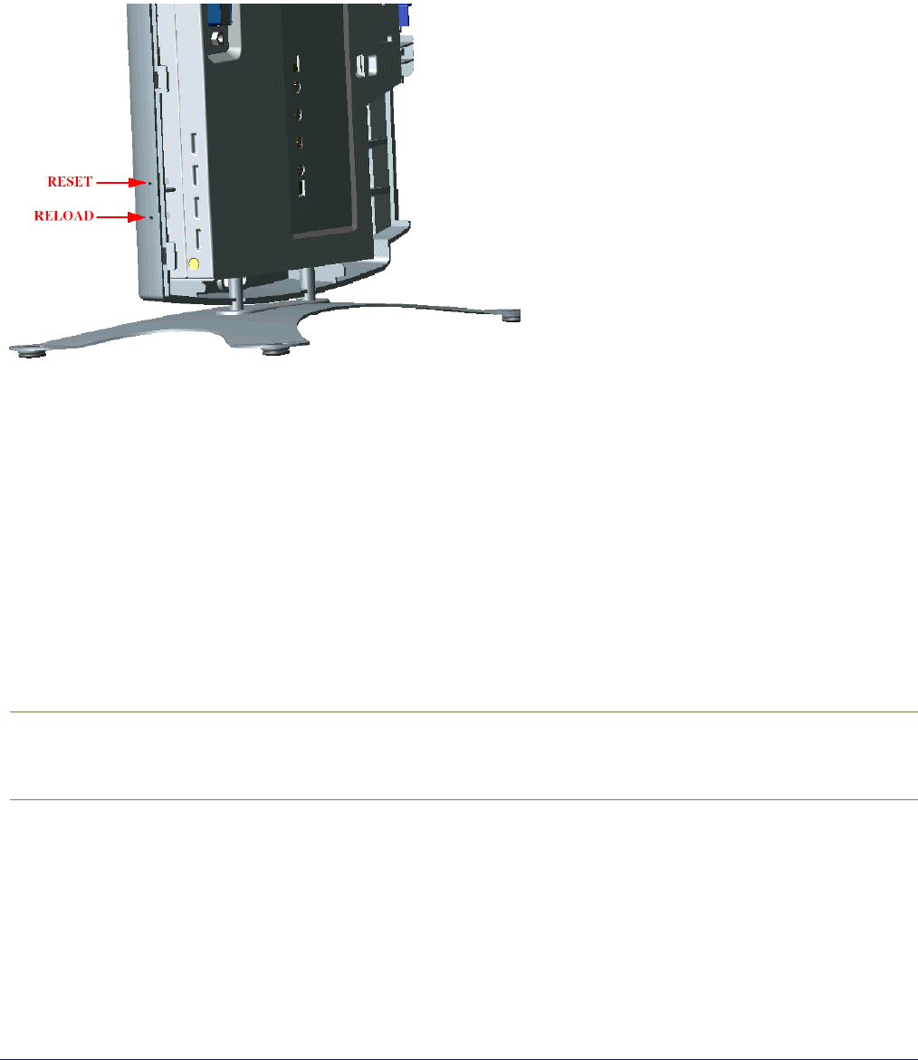
MP.11 and MP.11/a Quick Install Guide
Chapter 7. Procedures 125
HARD RESET TO FACTORY DEFAULT
Indoor MP.11/a
If you cannot access the unit or you have lost its password, you can reset the MP.11/a to the factory default
settings. Resetting to default settings means you must configure the MP.11/a anew.
To reset to factory default settings, press and hold the RELOAD button on the MP.11/a unit for about 10 seconds.
The MP.11/a reboots and restores the factory default settings.
To access the MP.11/a see “Chapter 3. Management Overview” on page 23.
Outdoor MP.11/a
To reset to factory default settings, use an object such as a paper clip to press and hold the Reset button located
on the side of the power brick.
FORCED RELOAD
With Forced Reload, you reset the MP.11/a to the factory default settings and erase the embedded software. Use
this procedure only as last resort if the MP.11/a does not boot and the “Reset to Factory Defaults” procedure did
not help. If you perform a Forced Reload, you must download a new image file with the Boot Loader (see “Image
File Download with the Boot Loader” below).
Caution! The following procedure erases the embedded software of the MP.11/a. This software image
must be reloaded through an Ethernet connection with a TFTP server. The image filename to
be downloaded can be configured with either ScanTool through the Ethernet interface or with
the Boot Loader CLI through the serial port to make the MP.11/a functional again.
To do a forced reload:
1. Press the RESET button on the MP.11/a unit; the MP.11/a resets and the LEDs flash.
2. Immediately press and hold the RELOAD button on the MP.11/a unit for about 20 seconds. Now image and
configuration are deleted from the unit.
3. Follow the procedure “Image File Download with the Boot Loader” to download an image file.

MP.11 and MP.11/a Quick Install Guide
Chapter 7. Procedures 126
IMAGE FILE DOWNLOAD WITH THE BOOTLOADER
The following procedures download an image file to the MP.11/a after the embedded software has been erased
with Forced Reload or when the embedded software cannot be started by the Boot Loader.
A new image file can be downloaded to the MP.11/a with ScanTool or the Command Line Interface through the
MP.11/a serial port. In both cases, the file is transferred through Ethernet with TFTP. Because the CLI serial port
option requires a serial RS-232C cable, Proxim recommends the ScanTool option.
Download with ScanTool
To download an image file with the ScanTool:
1. Set up the TFTP server as described in “TFTP Server Setup” on page 122.
2. Run ScanTool on a computer that is connected to the same LAN subnet as the MP.11/a. ScanTool scans the
subnet for MP.11/a units and displays the found units in the main window. If in Forced Reload, ScanTool
does not find the device until the MP.11/a bootloader times out, and the Power LED turns RED and the
Ethernet LED goes OFF. Click Rescan to re-scan the subnet and update the display.
3. Select the MP.11/a to which you want to download an image file and click Change.
4. Ensure that IP Address Type Static is selected and fill in the following details:
º Password
º IP Address and Subnet Mask of the MP.11/a.
º TFTP Server IP Address and, if necessary, the Gateway IP Address of the TFTP server.
º Image File Name of the file with the new image.
5. Click OK to start the file transfer.
The MP.11/a downloads the image file. The TFTP server program should show download activity after a few
seconds. When the download is complete, the LED pattern should return to Forced Reload state. the
MP.11/a is ready to start the embedded software.
6. Press and release the Reset button. It may take several seconds to cycle through the Forced Reload LED
pattern and through the initialization LED sequence.
After a Forced Reload procedure, the MP.11/a returns to factory default settings and must be reconfigured.
ScanTool can be used to set the system name and IP address.
To access the MP.11/a see “Chapter 3. Management Overview” on page 23.

MP.11 and MP.11/a Quick Install Guide
Chapter 7. Procedures 127
Download with CLI
To use the CLI through the serial port of the MP.11/a you need a serial RS-232C cable with a male and a female
DB-9 connector, and an ASCII terminal program such as HyperTerminal. Proxim recommends you switch off the
MP.11/a and the computer before connecting or disconnecting the serial RS-232C cable.
To download an image file:
1. Set up the TFTP server as described in “TFTP Server Setup” on page 122.
2. Start the terminal program (such as HyperTerminal), set the following connection properties, and then
connect:
COM port (for example COM1 or COM2, to which the MP.11 serial port is connected)
Bits per second 9600
Data bits 8
Stop bits 1
Flow control None
Parity None
3. Press the RESET button on the MP.11/a unit; the terminal program displays Power On Self Test (POST)
messages.
4. When the Sending Traps to SNMP manager periodically message is displayed after about 30
seconds, press the ENTER key.
5. The command prompt is displayed; enter the following commands:
set ipaddr <IP address MP.11>
set ipsubmask <subnet mask>
set ipaddrtype static
set tftpipaddr <IP address TFTP server>
set tftpfilename <image file name>
set ipgw <gateway IP address>
reboot
For example:
set ipaddr 10.0.0.12
set ipsubmask 255.255.255.0
set ipaddrtype static
set tftpipaddr 10.0.0.20
set tftpfilename image.bin
set ipgw 10.0.0.30
reboot
The MP.11/a reboots and downloads the image file. The TFTP server program should show download activity
after a few seconds. When the download is complete, the MP.11/a is ready for configuration.
To access the MP.11/a see “Chapter 3. Management Overview” on page 23. Note that the IP configuration in
normal operation differs from the IP configuration of the Boot Loader.

MP.11 and MP.11a Installation and Management
Chapter 2. Installation 128
Appendix A. Specifications
MP.11/A HARDWARE
Physical Specifications (without metal base)
Dimensions (h x w x l) 3.5 x 17 x 21.5 cm (1.5 x 6.75 x 8.5 in.)
Weight 0.68 kg (1.5 lb.)
Electrical Specifications
Using the Power Adapter
Voltage (Input) 100 to 240 VAC (50-60 Hz) @ 0.4 A
Voltage (Output) 12 VDC
Power Consumption 10 Watts (maximum)
Using Active Ethernet
Input Voltage 42 to 60 VDC
Output Current 200mA at 48V
Power Consumption 10 Watts
Environmental Specifications
Operating Temperature 0º to 55º C ambient temperature (without plastic cabinet)
Operating Humidity 95% maximum (non-condensing)
Storage Temperature -20º to +75º C ambient temperature
Storage Humidity 95% maximum (non-condensing)
Interfaces
Ethernet 10/100 Base-TX, RJ-45 female socket
Serial port Standard RS-232C interface with DB-9, female connector
Active Ethernet Category 5, foiled, twisted pair cables must be used to ensure compliance with
FCC Part 15, subpart B, Class B requirements.
Standard 802.3af pin assignments.
Wireless Mini PC Card
RUGGEDIZED MP.11/A
Operating Temperature -30º to +60º C
Wind and Water 125 mph winds, watertight (ETSI IP 64)
Weight Under 29 lbs
External Interfaces N-connector for external antenna
PoE or power and Ethernet cable
Serial port for antenna alignment, diagnostics, and management
Integrated Antenna on SU products, 23 dBi (5 GHz) or 16 dBi (2.4 GHz)
Audio antenna alignment

MP.11 and MP.11/a Quick Install Guide
Appendix A. Specifications 129
BROADBAND SUBSCRIBER ANTENNA
Mars 5 GHz Broadband Antenna provides a cost-effective solution for large-scale WLL, WLAN, H-LAN, ISM,
UNII, and Point-to-Multipoint applications.
Additional features include:
• Minimum gain of 23 dBi over the entire frequency range
• Lightweight and durable construction
• DC grounded for lightning protection to meet local electrical building codes.
Specifications
Electrical
Frequency range 5.15 – 5.875 GHz
GAIN, min. 23 dBi
VSWR, max. 1.5:1
Polarization Linear Vertical
3 dB Beamwidth – Az./El. typ. 10.5º
Cross Polarization, min. 24 dB
Power Handling 10 Watts
Input Impedance 50 Ohms
Front-to-back ratio, min. 35 dB
Mechanical and Environmental
Dimensions (LxWxD) 305 x 305 x 15mm (DIAMOND shape)
Base Plate Aluminum
Radome Polypropylene, UV-protected
Temperature -40º C up to +75º C
Input/RF Interface N-Type
Standard Compliance
ETSI EN 302 085 V1.1.2 (2001-2002) Range 1, TS 1, 2, 3, 4, 5

MP.11 and MP.11/a Quick Install Guide
Appendix A. Specifications 130
RADIO SPECIFICATIONS
802.11b Channel Allocations
The following table shows MP.11 (802.11b) channel allocations that vary from country to country. Values listed in
bold indicate default channels and frequencies.
Channel ID FCC/World (GHz) ETSI (GHz) France (GHz) Japan (GHz)
1 2.412 2.412 -- 2.412
2 2.417 2.417 -- 2.417
3 (default in most countries) 2.422 2.422 -- 2.422
4 2.427 2.427 -- 2.427
5 2.432 2.432 -- 2.432
6 2.437 2.437 -- 2.437
7 2.442 2.442 -- 2.442
8 2.447 2.447 -- 2.447
9 2.452 2.452 -- 2.452
10 2.457 2.457 2.457 2.457
11 (default in France) 2.462 2.462 2.462 2.462
12 -- 2.467 2.467 2.467
13 -- 2.472 2.472 2.472
14 2.484
80211.a Channel Allocations
The following table shows MP.11a (802.11a) channel allocations that vary from country to country. Values listed
in bold indicate default channels and frequencies.
Channel
ID FCC ETSI
56 5.280 ─
60 5.300 ─
64 5.320 ─
100 5.500 5.500
104 5.520 5.520
108 5.540 5.540
112 5.560 5.560
116 5.580 5.580
120 5.600 5.600
124 5.620 5.620
128 5.640 5.640
132 5.660 5.660
136 5.680 5.680
140 5.700 5.700
149 5.745 ─
153 5.765 ─
157 5.785 ─
161 5.805 ─
165 5.825 ─
Turbo channel ID 1, 5.290 – The MP.11a firmware limits the upper limit of this channel to be below 12.13 dBm for
release in the United States and Canada.

MP.11 and MP.11/a Quick Install Guide
Appendix A. Specifications 131
Turbo Mode Channels
Channel ID FCC
1 5.290*
2 5.300
3 5.760
4 5.800
Frequency Bands in the FCC Regulatory Domain
20 MHz Channelization
The set of valid operating channels, channel center frequencies, and DFS requirement for different bands in the
FCC regulatory domain is provided in the following table.
20 MHz Channelization
Regulatory
Domain Band (GHz) Operating Channel
Numbers Center Frequencies
(MHz) DFS Capability
U-NII Middle Band
5.25 – 5.35 GHz
56
60
64
5280
5300
5320
Required
FCC
U-NII Upper Band
5.725 – 5.825 GHz
149
153
157
161
165
5745
5765
5785
5805
5825
Not Required

MP.11 and MP.11a Installation and Management
Chapter 2. Installation 132
Appendix B. Troubleshooting
This chapter helps you to isolate and solve problems with your MP.11/a. In the event this chapter does not
provide a solution, or the solution does not solve your problem, check our support website at
http://support.proxim.com/
Before you start troubleshooting, it is important that you have checked the details in the product documentation.
For details about RADIUS, TFTP, terminal and telnet programs, and Web browsers, refer to their appropriate
documentation.
The following sections can help to solve your problem:
• LED Indicators below
• MP.11/a Connectivity Issues below
• Setup and Configuration Issues on page 134
In some cases, rebooting the MP.11/a clears the problem. If nothing else helps, consider a “Soft Reset to Factory
Defaults” (on page 34) or a “Forced Reload” (on page 125). The Forced Reload option requires you to download
a new image file to the MP.11/a.
MP.11/a CONNECTIVITY ISSUES
The issues described in this section relate to the connections of the MP.11/a.
MP.11/a Does Not Boot
The MP.11/a shows no activity (the power LED is off).
1. Ensure that the power supply is properly working and correctly connected.
2. Ensure that all cables are correctly connected.
3. Check the power source.
4. If you are using an Active Ethernet splitter, ensure that the voltage is correct.
Serial Link Does Not Work
The MP.11/a cannot be reached through the serial port.
1. Check the cable connection between the MP.11/a and the computer.
2. Ensure that the correct COM port is used.
3. Start the terminal program; set the following connection properties (also see “HyperTerminal Connection
Properties” on page 31), and then connect.
COM port For example, COM1 or COM2, to which the MP.11 serial port is connected
Bits per second 9600
Data bits 0
Stop bits 1
Flow control None
Parity None
Line ends Carriage return with line feed
4. Ensure that the MP.11/a and the computer use the same serial port configuration parameters.
5. Press the RESET button on the MP.11/a unit. The terminal program displays Power On Self Tests (POST)
messages and displays the following after approximately 90 seconds:
Please enter password:
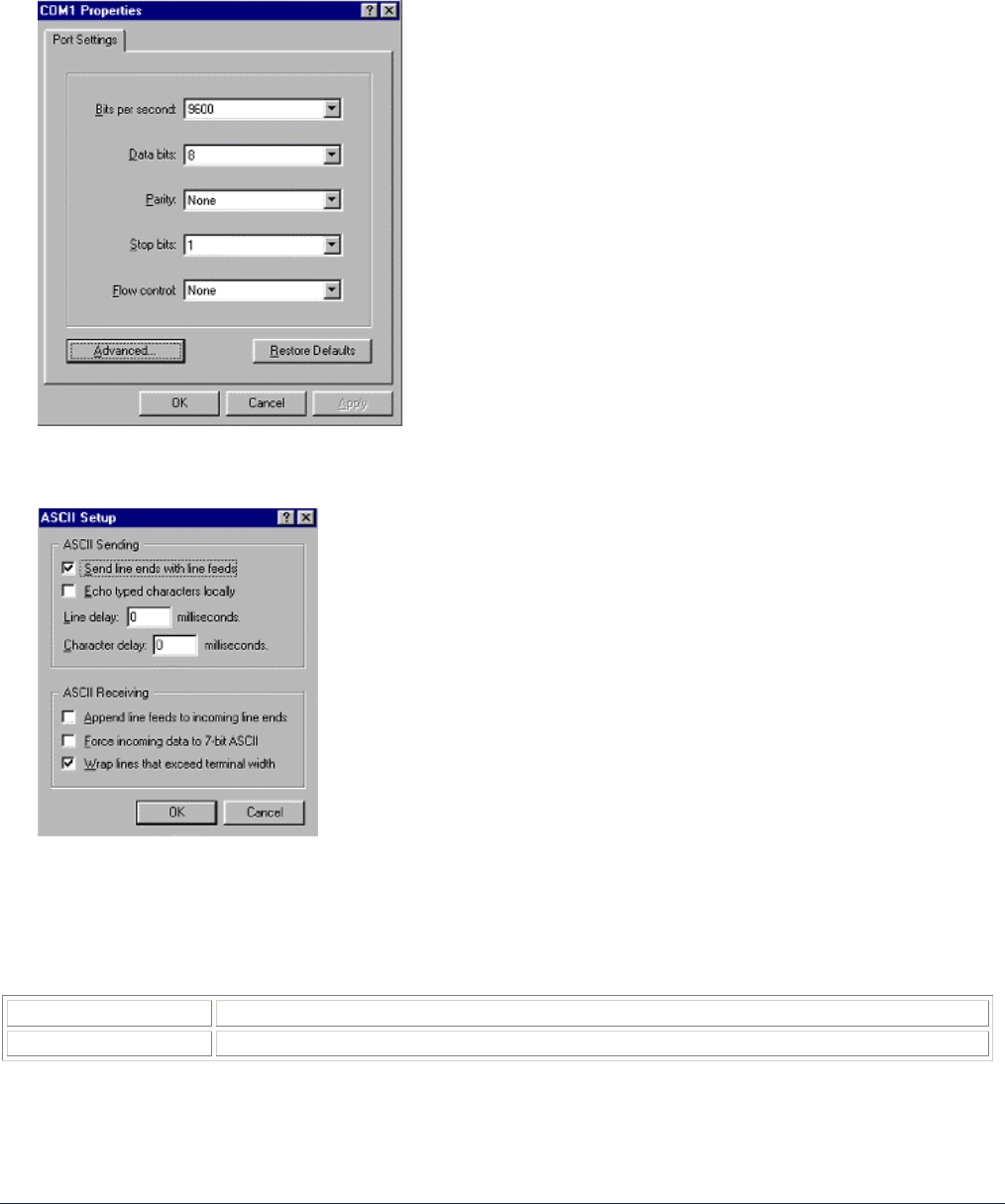
MP.11 and MP.11/a Quick Install Guide
Appendix B. Troubleshooting 133
HyperTerminal Connection Problems
The serial connection properties can be found in HyperTerminal as follows:
1. Start HyperTerminal and select Properties from the File menu.
2. Select Direct to Com 1 in the Connect using: drop-down list (depending upon the COM port you use); then
click Configure. A window such as the following is displayed:
3. Make the necessary changes and click OK.
4. Click the Settings tab and then ASCII Setup…. A window similar to the following is displayed:
5. Ensure that Send line ends with line feeds is selected and click OK twice. HyperTerminal is now correctly
configured.
Ethernet Link does not work
First check the Ethernet LED;
GREEN Power is on, the radio is up, and the Ethernet link is also up..
BLINKING GREEN Power is on, the radio is coming up and the Ethernet is down.
Verify pass-through versus cross-over cable.

MP.11 and MP.11/a Quick Install Guide
Appendix B. Troubleshooting 134
Cannot use the Web Interface:
1. Open a command prompt window and enter ping <ip address MP.11> (for example ping 10.0.0.1).
If the MP.11/a does not respond, make sure that you have the correct IP address.
If the MP.11/a responds, the Ethernet connection is working properly, continue with this procedure.
2. Ensure that you are using one of the following Web browsers:
º Microsoft Internet Explorer version 5.0 or later (Version 6.0 or later recommended)
º Netscape version 6.0 or later.
3. Ensure that you are not using a proxy server for the connection with your Web browser.
4. Ensure that you have not exceeded the maximum number of Web Interface or CLI sessions.
5. Double-check the physical network connections. Use a well-known unit to ensure the network connection is
properly functioning.
6. Perform network infrastructure troubleshooting (check switches, routers, and so on).
SETUP AND CONFIGURATION ISSUES
The following issues relate to setup and configuration problems.
Lost the MP.11/a Password
If you lost your password, you must reset the MP.11/a to the default settings. See “Hard Reset to Factory Default”
on page 125. The default password is public.
If you record your password, keep it in a safe place.
The MP.11/a Responds Slowly
If the MP.11/a takes a long time to become available, it could mean that:
• No DHCP server is available.
• The IP address of the MP.11/a is already in use.
Verify that the IP address is assigned only to the MP.11/a. Do this by switching off the MP.11/a and then
pinging the IP address. If there is a response to the ping, another device in the network is using the same IP
address. If the MP.11/a uses a static IP address, switching to DHCP mode could remedy this problem. Also
see “Setting the IP Address” on page 24.
• There is too much network traffic.
Web Interface Does Not Work
If you cannot connect to the MP.11/a Web server through the network:
1. Connect a computer to the serial port of the MP.11/a and check the HTTP status. The HTTP status can
restrict HTTP access at different interfaces. For more information, see “Serial Port” on page 30.
2. Open a command prompt window and enter:
ping <ip address MP.11> (for example ping 10.0.0.1)
If the MP.11/a does not respond, ensure that you have the correct IP address. If the MP.11/a responds, the
Ethernet connection is working properly, continue with this procedure.

MP.11 and MP.11/a Quick Install Guide
Appendix B. Troubleshooting 135
3. Ensure that you are using one of the following Web browsers:
º Microsoft Internet Explorer version 5.0 or later (Version 6.0 or later recommended)
º Netscape version 6.0 or later
4. Ensure that you are not using a proxy server for the connection with your Web browser.
5. Ensure that
you have not exceeded the maximum number of Web Interface sessions.
Command Line Interface Does Not Work
If you cannot connect to the MP.11/a through the network:
1. Connect a computer to the serial port of the MP.11/a and check the SNMP table. The SNMP table can restrict
telnet or HTTP access. For more information, see “Serial Port” on page 30.
2. Open a command prompt window and enter: ping <ip address MP.11>
(for example ping 10.0.0.1).
º If the MP.11/a does not respond, ensure that you have the correct IP address.
º If the MP.11/a responds, the Ethernet connection is working properly; continue with this procedure.
3. Ensure that you have not exceeded the maximum number of CLI sessions.
TFTP Server Does Not Work
With TFTP, you can transfer files to and from the MP.11/a. Also see “TFTP Server Setup” on page 122. If a
TFTP server is not properly configured and running, you cannot upload and download files. The TFTP server:
• Can be situated either local or remote
• Must have a valid IP address
• Must be set for send and receive without time-out
• Must be running only during file upload and download
If the TFTP server does not upload or download files, it could mean:
• The TFTP server is not running
• The IP address of the TFTP server is invalid
• The upload or download directory is not correctly set
• The file name is not correct
Online Help Is Not Available
Online help is not available
1. Make sure that the Help files are installed on your computer or server. Also see “Installing Documentation
and Software” on page 21.
2. Verify whether the path of the help files in the Web Interface refers to the correct directory. See “Help” on
page 93.
Changes Do Not Take Effect
Changes made in the Web Interface do not take effect:
1. Restart your Web browser. Log into the MP.11/a again and make changes. Reboot the MP.11/a when
prompted to do so.
2. Wait until the reboot is completed before accessing the MP.11/a again.

MP.11 and MP.11a Installation and Management
Appendix C. Support and Contacts 136
Appendix C. Support and Contacts
If you are having a problem using a Proxim WAN product and cannot resolve it with the information in the product
documentation, gather the following information and contact Proxim Technical Support:
• What kind of network are you using?
• What were you doing when the error occurred?
• What error message did you see?
• Can you reproduce the problem?
Be sure to obtain an RMA number before sending any equipment to Proxim for repair.
To receive E-mail technical support, be sure to include the serial number of the product(s) in question. The serial
number should be on the product and conform to the following format: ##UT######## or ##R7########. We are
unable to respond to your inquiry without this information.
USA & Canada Customers
Call Technical Support: WAN Toll Free
866-674-6626 or
408-542-5390
Hours: 6:00 AM to 5:00 PM M-F Pacific Time
LAN Toll Free
866-674-6626 Hours: 24x7
International Customers
Call Technical Support:
WAN 408-542-5390
Hours: 6:00 AM to 5:00 PM M-F Pacific Time
LAN 408-542-5390 Hours: 24x7
Search Knowledgebase: http://support.proxim.com/
Latest software and documentation: http://support.proxim.com/

MP.11 and MP.11a Installation and Management
Glossary 137
Glossary
Address Realm
An address realm is a network domain in which the
network addresses are uniquely assigned to entities such
that datagrams can be routed to them.
Application Level Gateway (ALG)
An Application Level Gateway is an application-specific
translation agent that provides the required transparency
for an application running on a host in a private network to
connect to its counterpart running on a host in the public
network. The NAT feature requires an ALG to support
certain applications.
ARP
The Address Resolution Protocol (ARP) is intended to find
the MAC address belonging to an IP address.
Authentication method
The process the MP.11/a uses to decide whether a station
that wants to register is allowed or not. IEEE 802.11
specifies two forms of authentication: open system and
shared key; WORP only supports shared key because of
security constraints.
Authentication server “Shared Secret”
This is a kind of password shared between the MP.11/a
and the RADIUS authentication server. This password is
used to encrypt important data exchanged between the
MP.11/a and the RADIUS server
Authentication server authentication port
This is a UDP port number (default is 1812), which is used
to connect to the authentication server for obtaining
authentication information.
Auto-Negotiation
A signaling method that lets each node define its
operational mode and detect the operational mode of the
adjacent node. Auto-negotiation can be used in dual-
function 10/100 Mbps Ethernet adapters. The process
happens out-of-band with no loss of network throughput.
Backbone
The central part of a network; the backbone network
connects all remote and sub networks to each other and to
the central infrastructure (such as the mail server, Internet
gateway, and so on).
Base
If an interface is running in Outdoor mode (WORP), it is
either a base or a subscriber interface. A base interface
controls the communication on the channel and is located
in the central part of the network cell. Multiple SUs can
connect to one base; two bases cannot communicate with
each other.
Broadcast Storm
A broadcast storm is a large series of broadcast packets
(most often caused by wrong network configuration) that
severely impact the network performance.
Client IP Address Pool
This a pool of IP addresses from which the MP.11/a can
assign IP addresses to clients, which perform a DHCP
Request.
Configuration Files
A configuration file contains the MP.11/a configuration
details. Configuration items include among others the IP
address and other network-specific values. Configuration
files may be uploaded to a TFTP server for backup and
downloaded into the MP.11/a for restoring the
configuration.
DHCP Relay Agent
A feature of the MP.11/a that intercepts DHCP requests
from clients and forwards them to a DHCP server. For the
client, the DHCP Relay Agent of the MP.11/a functions like
a DHCP server. This enables DHCP requests to pass
router boundaries; for example, it is not required to have a
DHCP server on every IP subnet.
Domain Name Server (DNS)
A domain name server is an Internet service that
translates domain names into IP addresses. For example,
www.ietf.org is translated into 4.17.168.6.
Download
Downloading a file means copying a file from a remote
server to a device or host. In case of the MP.11/a
downloading means transferring a file from a TFTP server
to the MP.11/a.
Downstream
Downstream means a data stream from the central part of
the network to the end user. See also upstream.
Dynamic Host Configuration Protocol
Dynamic Host Configuration Protocol (DHCP) is a method
to dynamically assign IP addresses. If DHCP is enabled,
the device or computer broadcasts a request that is
answered by a DHCP Server.
Encryption
Encryption is a means of coding data with a key before
sending it across a network. The same key must be used
to decode the information at the receiver. This way
prevents unauthorized access to the data that is send
across the network.
Ethernet
Ethernet is the most widely installed Local Area Network
(LAN) technology. The MP.11/a supports both 10 and 100
Mbps and half and full duplex.
Gateway
A gateway is network device that connects multiple (IP)
networks to each other. A gateway can perform protocol
conversion.

MP.11 and MP.11/a Quick Install Guide
Glossary 138
Group
A group is logical collection of network parameters. For
example, the System Group is composed of several
parameters and tables giving system information of the
MP.11/a. All items for a group are grouped under one tab
of the Web Interface and start with the same prefix for the
command line interface.
HTTP
Hypertext Transfer Protocol (HTTP) is the protocol to
transport Web pages. When you access the Internet with
your browser, the HTTP protocol is used for data transport
(http://www.Tsunamiwireless.com). When you access the
MP.11/a using the Web Interface, HTTP is used to
transport the information.
ICMP
Internet Control Message Protocol (ICMP) is used by
computers and devices to report errors encountered
during processing packets, and to perform other IP-layer
functions, such as diagnostics (‘ping’).
Image
The image is the binary executable of the embedded
MP.11/a software. To update the MP.11/a you must
download a new image file.
IP Address
A unique numerical address of a computer attached to the
Internet or Intranet. An IP (Internet Protocol) address
consists of a network part and part for a host (computer)
number. An IP address is represented by four numbers in
the range 0 - 255 separated by dots: for example
10.0.10.1 and 172.21.43.214. See also subnet mask.
LAN
A Local Area Network (LAN) is a network of limited size to
which computers and devices can connect so that they
can communicate with each other.
License file
A license file is used to enable certain features of the
MP.11/a. The MP.11/a already has a license file when it is
shipped. When more features become available, you can
purchase a license file and download it to the MP.11/a to
enable these additional features.
MAC
Media Access Control.
MAC Address
A MAC (Media Access Control) address is a globally
unique network device address, which is hardware bound.
It used to identify a network device in a LAN. A MAC
address is represented by six two-digit hexadecimal
numbers (0 - 9 and A - F) separated by colons: for
example 00:02:2D:47:1F:71 and 00:D0:AB:00:01:AC.
Management Information Block (MIB)
A Management Information Block (MIB) is a formal
description of a set of network objects that can be
managed with the Simple Network Management Protocol
(SNMP). A MIB can be loaded by a management
application so that it knows the MP.11/a specific objects.
Media Independent Interface (MII)
A standard interface between the MAC layer and any of
the three physical layers (100 Base-TX, 100 Base-T4, and
100 Base-FX) for Fast Ethernet, similar to the AUI
interface for traditional Ethernet.
Network Address Translation
Network Address Translation is a method by which IP
addresses are mapped from one address realm to
another, providing transparent routing to end hosts.
Network Mask
See subnet mask.
Parameter
A parameter is fundamental value that can be displayed
and changed. For example, the MP.11/a must have a
unique IP address and the PC Cards must know which
channels to use. You can view and change parameters
with the Web Interface, command line interface and
SNMP.
Password
The MP.11/a is password protected. To access the
MP.11/a you need to enter a password before you can
view or change its settings. The default password is
‘public’.
Ping
Ping is a basic Internet program that lets you verify if a
particular computer or device with a certain IP address is
reachable. If the computer or device receives the ping
packet, it responds which gives the ping program the
opportunity to display the round-trip time.
Remote
A remote is a base or a subscriber interface. For a base
interface, the number of remotes is the number of SUs
registered; for a subscriber interface, there is only one
remote, which is the base.
RIP
Routing Information Protocol (RIP) is used between
routers to update routing information so that a router
automatically ‘knows’ which port to use for a certain
destination IP address.
Router
Routers forward packets from one network to another
based on routing information. A router uses a dynamic
routing protocol like RIP or static routes to base its
forwarding decision on.
ScanTool
A computer program that can be used to retrieve or set the
IP address of a locally connected MP.11/a.

MP.11 and MP.11/a Quick Install Guide
Glossary 139
Simple Network Management Protocol (SNMP)
A protocol used for the communication between a network
management application and the devices it is managing.
The network management application is called the SNMP
manager; the devices it manages have implemented
SNMP agents. Not only the MP.11/a but also almost every
network device contains a SNMP agent. The manageable
objects of a device are arranged in a Management
Information Base, also called MIB. The Simple Network
Management Protocol (SNMP) allows managers and
agents to communicate for accessing these objects.
Spanning Tree Protocol (STP)
The Spanning Tree Protocol (STP) can be used to create
redundant networks (“hot standby”) and to prevent loops.
If enabled, spanning tree prevents loops by disabling
redundant links; if a link fails, it can automatically enable a
backup link.
STP
Shielded Twisted Pair
Subnet Mask
A subnet mask is a bit mask that defines which part of an
IP address is used for the network part and which part for
a host (computer) number. A subnet mask is like an IP
address represented by four numbers in the range 0 - 255
separated by dots. When the IP address 172.17.23.14 has
a subnet mask of 255.255.255.0, the network part is
172.17.23 of the host number is 14. See also IP address.
Subscriber Unit
If an interface is running in outdoor mode (WORP), it is
either a base or a subscriber interface. Subscriber
interface behavior is controlled by the base to which it is
registered. SUs are located in the remote locations of a
network cell. Multiple SUs can connect to one base; two
SUs cannot communicate with each other. See also
WORP and base.
Table
Tables hold parameters for several related items. For
example, you can add several potential managers to the
SNMP IP access table. Tables can be displayed using
with the Web Interface, command line interface and
SNMP.
Topology
Topology is the physical layout of network components
(cable, stations, gateways, hubs, and so on).
Transparent Routing
Transparent routing refers to routing a datagram between
disparate address realms, by modifying address contents
in the IP header to be valid in the address realm into which
the datagram is routed.
Trap
A trap is used within SNMP to report an unexpected or
unallowable condition.
Trivial File Transfer Protocol (TFTP)
Trivial File Transfer Protocol (TFTP) is a lightweight
protocol for transferring files that is like a simple form of
File Transfer Protocol (FTP). A TFTP client is
implemented on the MP.11/a; using the upload and
download commands, the MP.11/a can respectively copy
a file to or from a TFTP server. TFTP server software is
provided on the MP.11/a CD-ROM.
Upload
Uploading a file means copying a file from a network
device to a remote server. In case of the MP.11/a
uploading means transferring a file from the MP.11/a to a
TFTP server. See also download.
Upstream
Upstream means a data stream from the end users to the
central part of the network. See also downstream.
UTP
Unshielded Twisted Pair
WEP
The Wired Equivalent Privacy (WEP) algorithm is the
standard encryption method used to protect wireless
communication from eavesdropping.
WORP
The Wireless Outdoor Router Protocol (WORP) was
designed to optimize long distance links and multipoint
networks with Hidden Node effect to eliminate collisions
and loss of bandwidth.