R tron SNTRIDC Wireless Booster(CDMA) User Manual RSN TRI 25 24 DC 0314 indd
R-tron Inc. Wireless Booster(CDMA) RSN TRI 25 24 DC 0314 indd
UserManual.wiki
>
R tron
>
SNTRIDC User Manual
>
User Manual 1
Contents
1.
User Manual 1
2.
User Manual 2
3.
User Manual 3
User Manual 1
Navigation menu
Upload a User Manual
Namespaces
Wiki Guide
HTML
PDF
Info
Views
User Manual
Discussion / Help
Navigation
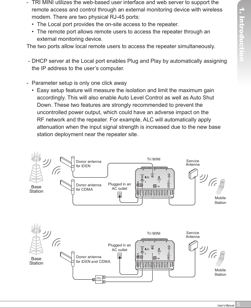
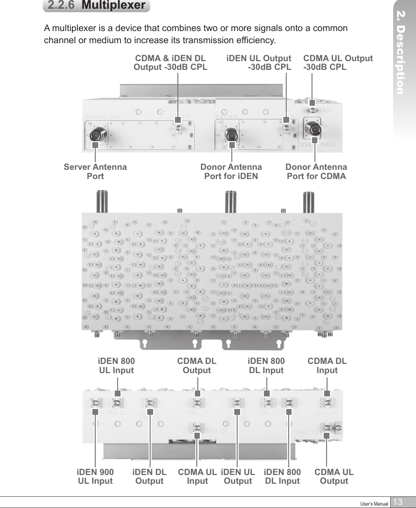
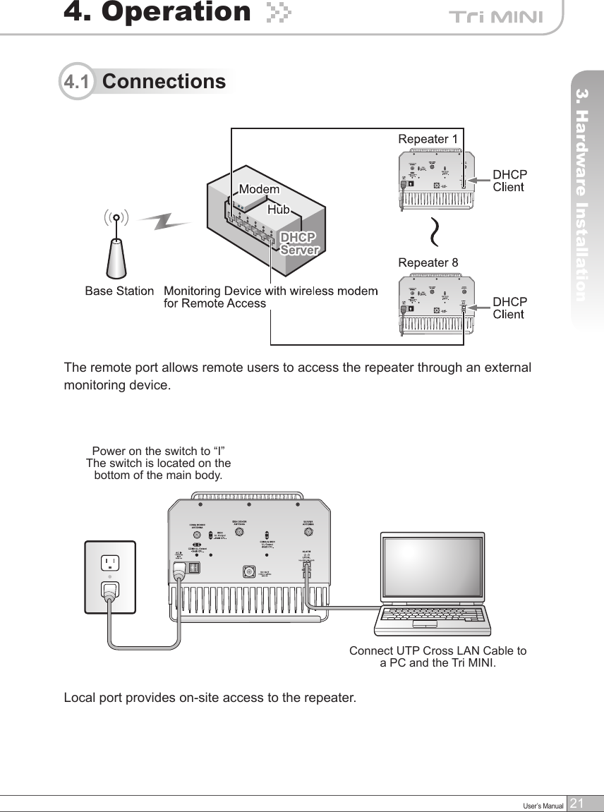
![4Tri MINI repeater is used to fill out areas in iDEN and CDMA mobile systems, such as base station fringe areas, business and industrial building, etc.Tri MINI receives signals from a base station, amplifies and retransmits the signals to mobile stations. Also it receives, amplifies and retransmits signals in the opposite direction. Both directions are served simultaneously with the following features:1. Introductiona. iDEN• 7MHz or 18MHz-bandwidth service @ 800MHz’s• 5MHz-bandwidth service @ 900MHz’s• Adjustable Band Edge @ 800MHz’s and 900MHz’s• Roll Offs: 65dBc at 0.5MHz outside pass-band• Remote Access and Control• Easy and Quick Installation - Web-based GUI - Plug and Play – DHCP Server @ Local Port an DHCP Client @ Remote Port - Easy Setup(Automatic) - Isolation Detection• Auto Level Control & Auto Shut Downb. CDMA• Programmable Bandwidth and Band - 5, 10, 15, and 20MHz contiguous and non-contiguous segments - Any Band Combination within 65MHz PCS Band [A, D, B, E, F, C, G] - Three(3) 5MHz segments• Remote Access and Control• Easy and Quick Installation - Web-based GUI - Plug and Play – DHCP Server @ Local Port an DHCP Client @ Remote Port - Easy Setup(Automatic) - Isolation Detection• Auto Level Control & Auto Shut Down](https://usermanual.wiki/R-tron/SNTRIDC.User-Manual-1/User-Guide-919392-Page-5.png)