R tron SNTRIDC Wireless Booster(CDMA) User Manual RSN TRI 25 24 DC 0314 indd
R-tron Inc. Wireless Booster(CDMA) RSN TRI 25 24 DC 0314 indd
UserManual.wiki
>
R tron
>
SNTRIDC User Manual
>
User Manual 3
Contents
1.
User Manual 1
2.
User Manual 2
3.
User Manual 3
User Manual 3
Navigation menu
Upload a User Manual
Namespaces
Wiki Guide
HTML
PDF
Info
Views
User Manual
Discussion / Help
Navigation

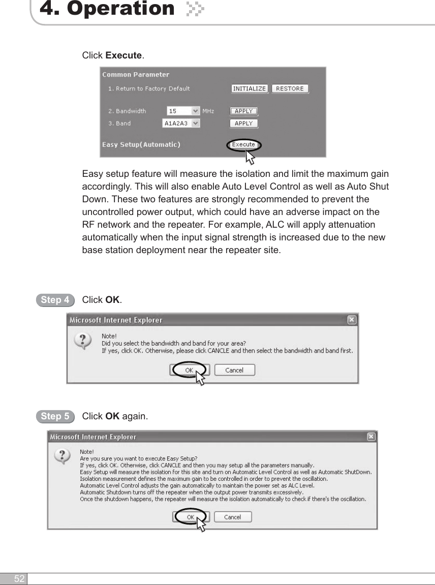
![51User’s Manual4. OperationSolution 1. Easy Setup [Recommended]Return To Factory DefaultsStep 1Select Bandwidth and Band and click APPLY.Step 2• To reset to factory defaults, click INITIALIZE.• To restore the previous settings, click RESTORE.Easy SetupStep 3Easy Setup proceeds to: • Isolation measurement On • Calculation of Available Maximum Gain by the isolation.• ASD On• ALC On to get Maximum DL Output Power 24dBm [Default] or Maximum Gain 80dB.](https://usermanual.wiki/R-tron/SNTRIDC.User-Manual-3/User-Guide-919394-Page-4.png)


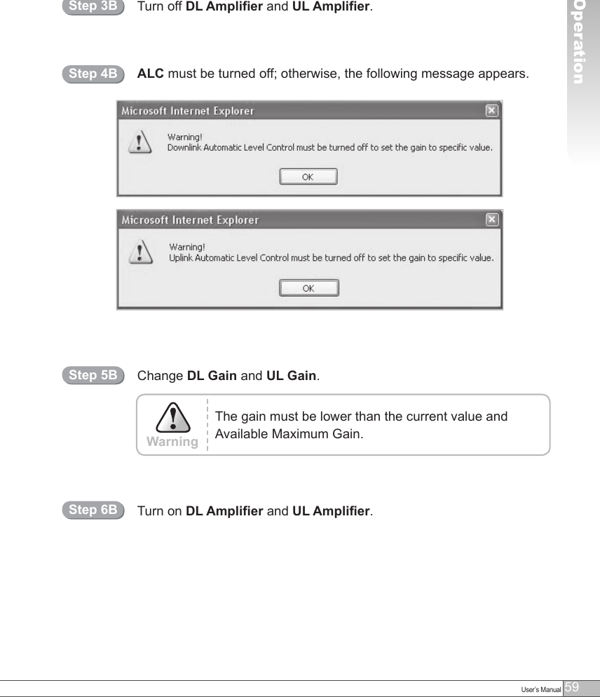
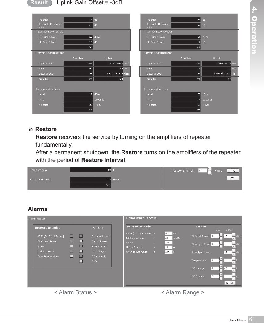
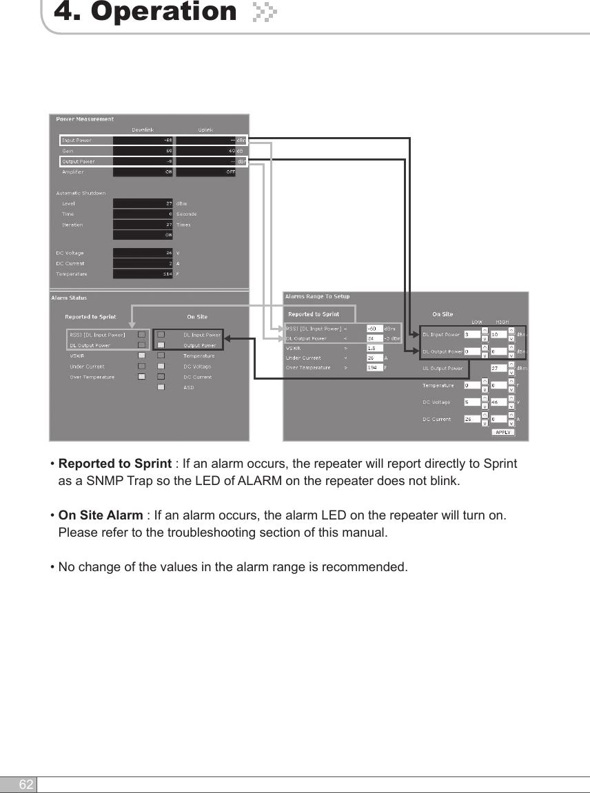
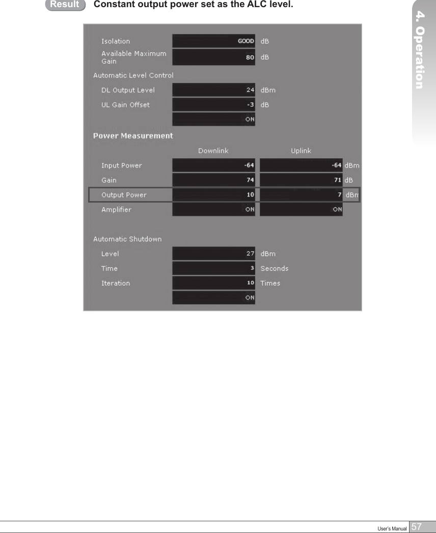
![57User’s Manual564. Operation4. OperationSolution 2. DL Output Power < Max. 24dBmRepeat step 1 through step 6.Step 2AStep 1AChange the level at Automatic Level Control and click APPLY.After running Easy Setup or Isolation Measurement, Isolation value is displayed with “95” when the isolation is higher than 95dB, or it is displayed with the actual value when the isolation is lower than 95dB.• Automatic Level Control: Type under 24 and then click APPLY and ON. [Example] For the repeater with 24dBm maximum output power, 80dB maximum gain/40dB gain control range, → If the signal -36dBm and the ALC is set as 24dBm, the gain will be 60dB to adjust to the output power. If the input signal is -61dBm, the output power will be 19dBm by the limitation of the maximum gain even though the ALC is set as 24dBm.• Automatic Shutdown: Type the desired values for dBm, seconds, and times and then click APPLY and ON. (e.g. 27 dBm, 10 seconds, 3 times) [Example] For the repeater with 24dBm maximum output power, 80dB maximum gain/40dB gain control range, Assuming ASD Level: 27dBm, ASD Time: 10seconds, ASD Count: 3. If the output power is 27dBm (ASD LEVEL) and higher, the repeater will shutdown for 10 seconds (ASD TIME). If shutdown occurs 3 times (ASD COUNT), the 4th shutdown will be permanent.](https://usermanual.wiki/R-tron/SNTRIDC.User-Manual-3/User-Guide-919394-Page-9.png)
![59User’s Manual584. Operation4. OperationSolution 3. Fixed Gain [Not Recommended]Easy Setup will calculate the Available Maximum Gain which defines the maximum gain to be setup.Repeat step 1 through step 6.Step 1BDO NOT setup the gain higher than the Available Maximum Gain.WarningRead DL Input Power and the gain controlled by Easy Setup. Step 2B](https://usermanual.wiki/R-tron/SNTRIDC.User-Manual-3/User-Guide-919394-Page-11.png)