R tron SNTRIDC Wireless Booster(CDMA) User Manual RSN TRI 25 24 DC 0314 indd
R-tron Inc. Wireless Booster(CDMA) RSN TRI 25 24 DC 0314 indd
UserManual.wiki
>
R tron
>
SNTRIDC User Manual
>
User Manual 2
Contents
1.
User Manual 1
2.
User Manual 2
3.
User Manual 3
User Manual 2
Navigation menu
Upload a User Manual
Namespaces
Wiki Guide
HTML
PDF
Info
Views
User Manual
Discussion / Help
Navigation


![344. OperationClick Network in the left menu.4.5.3 NetworkNetwork Setup• Cascade Code: Type in the pre-assigned code. Otherwise, you cannot access system setup.• Location Information: Enter the latitude and longitude of a location, otherwise you cannot access the system setup. You can input either Decimal Degrees or Degrees-Minutes-Seconds. [Example.] (‘N/S ‘ | ‘E/W ‘) ddd.dddddd: (Latitude: N 39.006957 Longitude: W 94.532306)• Heartbeat Interval: Sets the time to transmit the Heartbeat to NMC Server. (Default value is 20 minutes. At the setup, temporarily reduce the value to 1 minute. After conforming heartbeat report, set the value back to 20 minutes.)• Product Information: This is for manufacturer used only. DO NOT change this value.• Static IP for Remote Control: Connect to the External Monitoring Device for Remote Access. Do not enter any value unless a static IP is assigned. DHCP client.• NMC Server IP: Do not change this value; otherwise, the Heartbeat transmission or Remote Access may not work.](https://usermanual.wiki/R-tron/SNTRIDC.User-Manual-2/User-Guide-919393-Page-11.png)
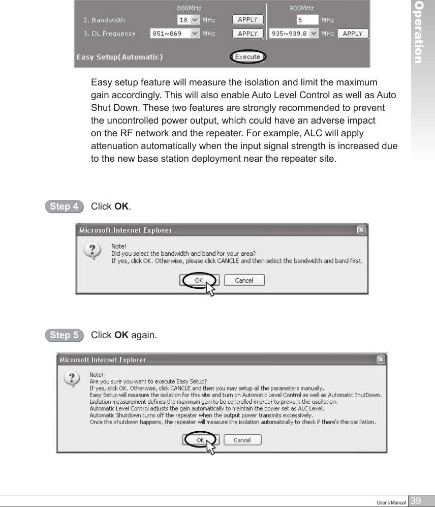
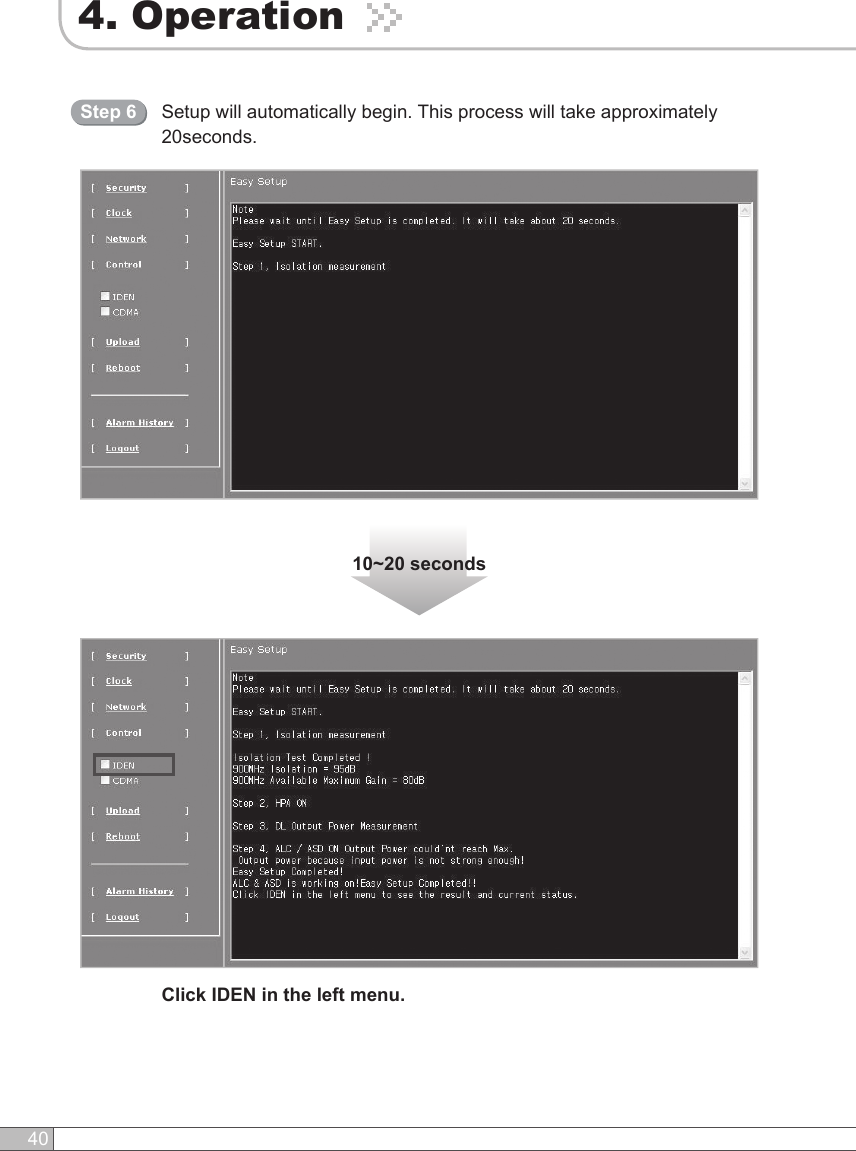
![384. OperationSolution 1. Easy Setup [Recommended]Return to Factory DefaultsStep 1• To reset factory defaults, click INITIALIZE.• To restore the previous settings, click RESTORE.Step 2 Select the operating bandwidth and operating frequencies (5MHz-bandwidth fixed in iDEN 900) and click APPLY.Easy SetupStep 3Easy Setup proceeds to:• Isolation measurement On• Calculation of Available Maximum Gain by the isolation.• ASD On• ALC On to get Maximum DL Output Power 25dBm [Defaults] or Maximum Gain 80dB. Click Execute.](https://usermanual.wiki/R-tron/SNTRIDC.User-Manual-2/User-Guide-919393-Page-15.png)
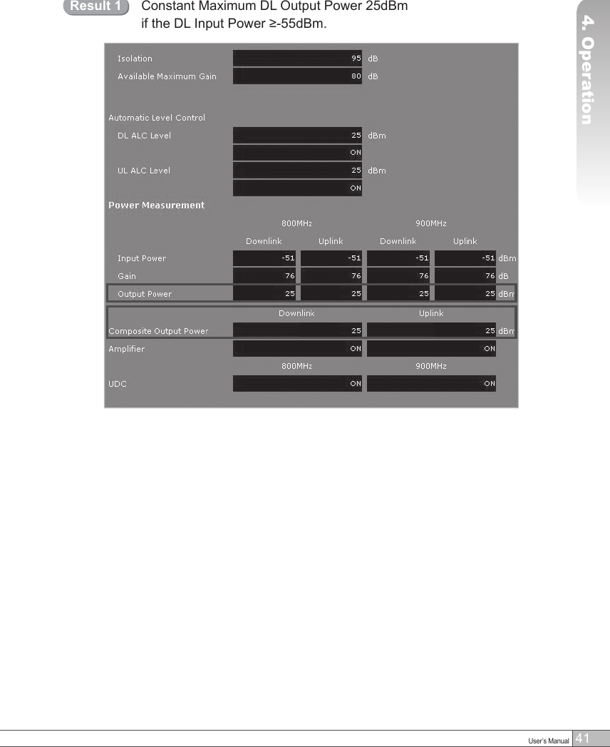
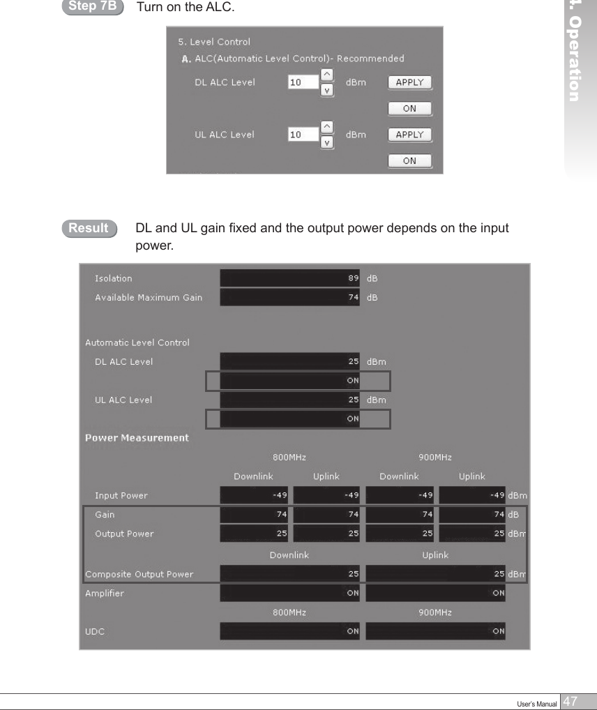
![424. OperationMaximum Gain 80dB if the DL Input Power <-55dBm.Result 2After running Easy Setup or Isolation Measurement, Isolation is displayed with “95” when the isolation is higher than 95dB, or it is displayed with the actual when the isolation is lower than 95dB.•Automatic Level Control: Type under 25 and then click APPLY and ON. [Example] For the repeater with 25dBm maximum output power, 80dB maximum gain / 30dB gain control range, → If the signal -45dBm and the ALC is set as 25dBm the gain will be 70dB to adjust to the output power. If the input signal is -60dBm, the output power will be 20dBm by the limitation of the maximum gain even though the ALC is set as 25dBm.](https://usermanual.wiki/R-tron/SNTRIDC.User-Manual-2/User-Guide-919393-Page-19.png)
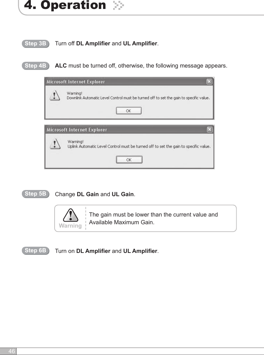
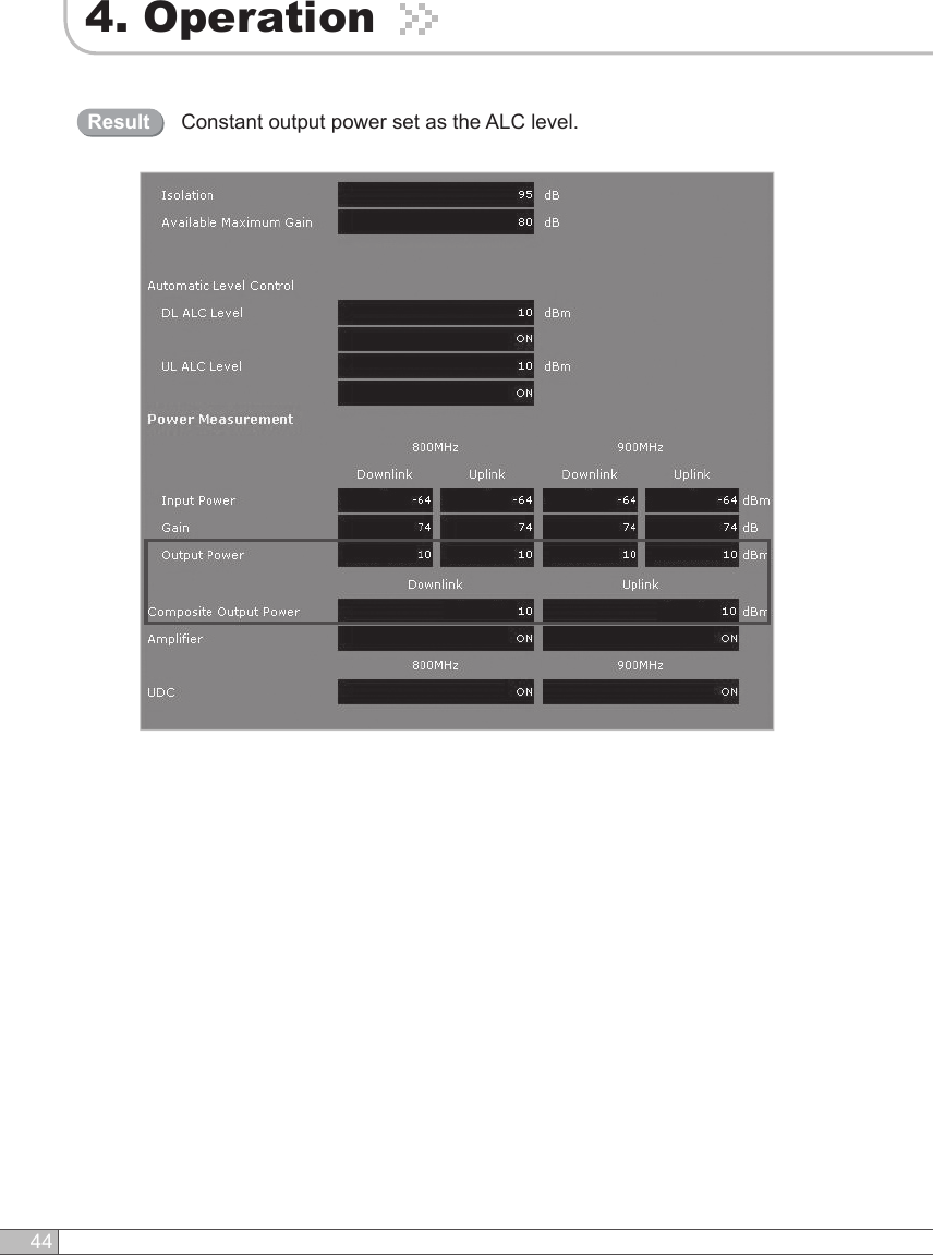
![43User’s Manual4. Operation• Automatic Shutdown: Type the desired values for dBm, seconds, and times and then click APPLY and ON.(e.g. 28dBm, 3seconds, 10times) [Example] For the repeater with 25dBm Maximum Output Power, 80dB Maximum Gain / 30dB gain control range, Assuming ASD Level: 28dBm, ASD Time: 3seconds, ASD Iteration: 10. If the output power is 28dBm(ASD LEVEL) and higher, the repeater will shutdown for 3 seconds(ASD TIME). If the shutdown occurs 10 times (ASD COUNT), the 10th shutdown will be permanent.Solution 2. DL Output Power < Max. 25dBmRepeater Step 1 through Step 6.Step 2AStep 1AChange the level at Automatic Level Control and click APPLY.](https://usermanual.wiki/R-tron/SNTRIDC.User-Manual-2/User-Guide-919393-Page-20.png)
![45User’s Manual4. OperationSolution 3. Fixed Gain [Not Recommended]Repeat Step 1 through Step 6.Easy Setup will calculate the Available Maximum Gain which defines the maximum gain to be setup.Step 1BRead DL Input Power and the gain controlled by Easy Setup.Step 2BDO NOT setup the gain higher than the Available Maximum Gain.Warning](https://usermanual.wiki/R-tron/SNTRIDC.User-Manual-2/User-Guide-919393-Page-22.png)