R tron SNTRIDC Wireless Booster(CDMA) User Manual RSN TRI 25 24 DC 0314 indd
R-tron Inc. Wireless Booster(CDMA) RSN TRI 25 24 DC 0314 indd
R tron >
Contents
- 1. User Manual 1
- 2. User Manual 2
- 3. User Manual 3
User Manual 2
24
4. Operation
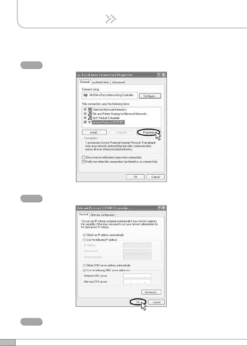
Select Internet Protocol (TCP/IP) and click Properties.
Step 4
Check Obtain an IP address automatically and click OK.
Step 5
Close all windows.
Step 6
25
User’s Manual
4. Operation
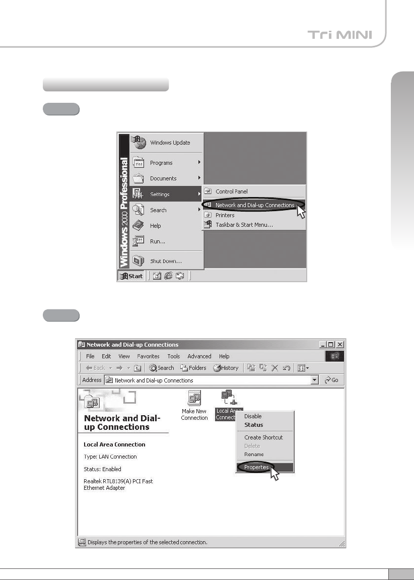
4.3.2 Windows 2000
Click the Start button, point to Settings, and then click Network and
Dial-up Connections.
Step 1
Right-click Local Area Connection to see a shortcut menu and click
Properties.
Step 2
26
4. Operation
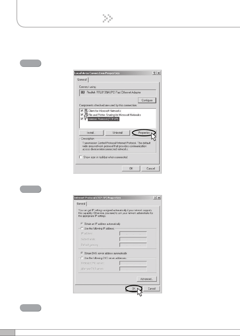
Select Internet Protocol (TCP/IP) and click Properties.
Step 3
Check Obtain an IP address automatically and click OK.
Step 4
Close all windows.
Step 5
27
User’s Manual
4. Operation
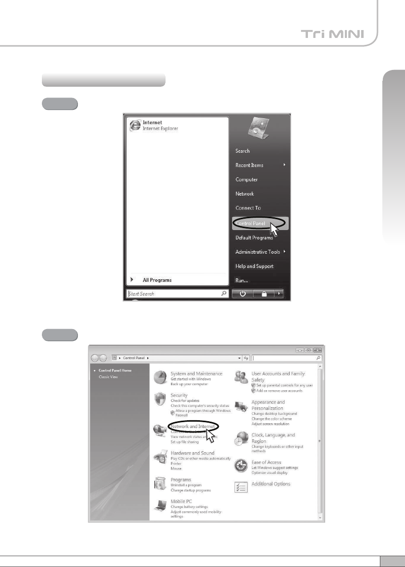
4.3.3 Windows Vista
Click the Start button and Control Panel.
Step 1
Click Network and Internet.
Step 2
28
4. Operation
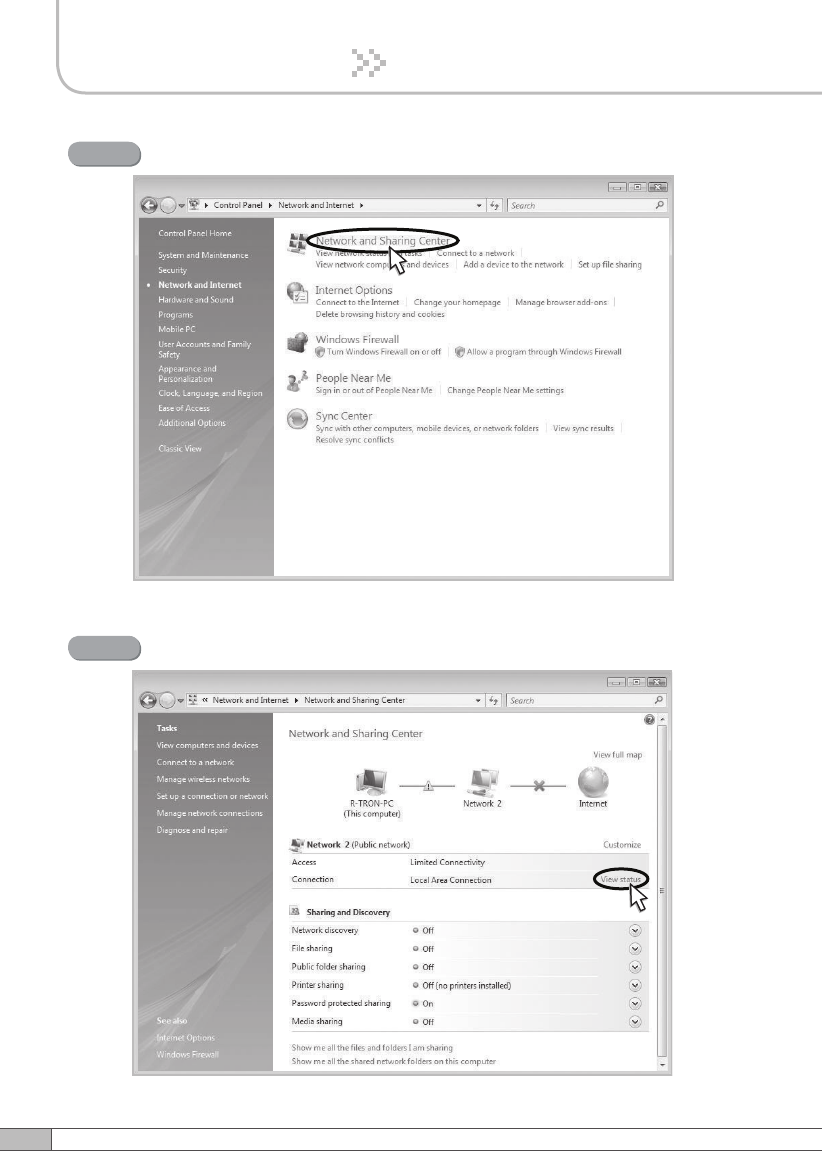
Click Network and Sharing Center.
Step 3
Click View status of Local Area Connection.
Step 4
29
User’s Manual
4. Operation
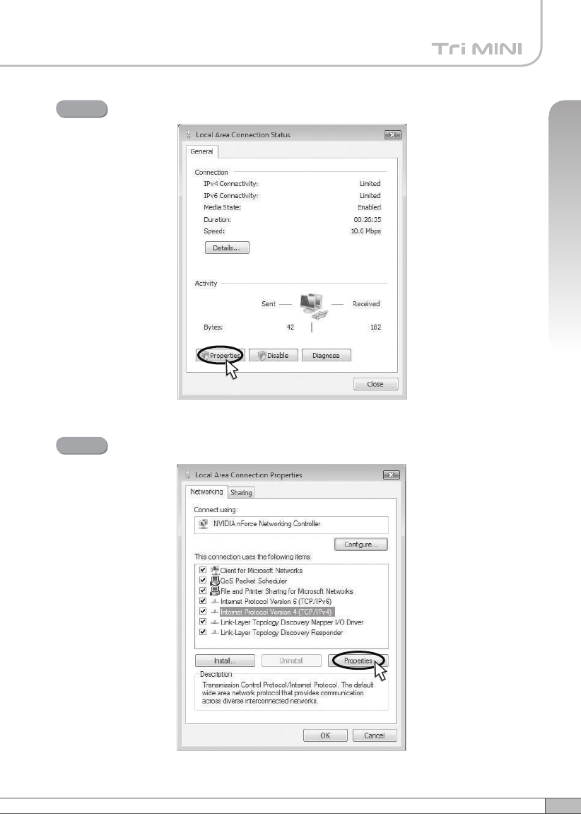
Click Properties and a caution pop-up window will appear. Click OK.
Step 5
Select Internet Protocol Version 4 (TCP/IPv4) and click Properties.
Step 6
30
4. Operation
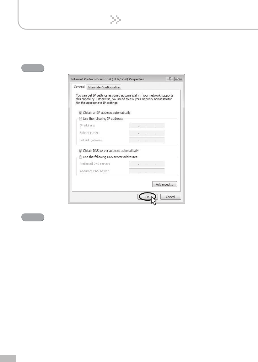
Check Obtain an IP address automatically and click OK.
Step 7
Close all windows.
Step 8
31
User’s Manual
4. Operation
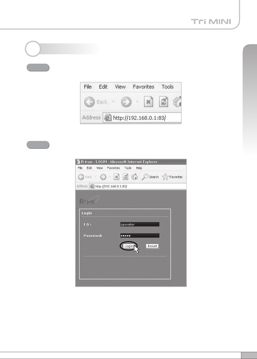
4.4 System Login
Open your Web browser and type “192.168.0.1:83” into the URL
address box. Then press the Enter key.
Step 1
The logon screen will appear. Type “operator” for the ID and “rtron” for
the password and then click OK.
Step 2
32
4. Operation
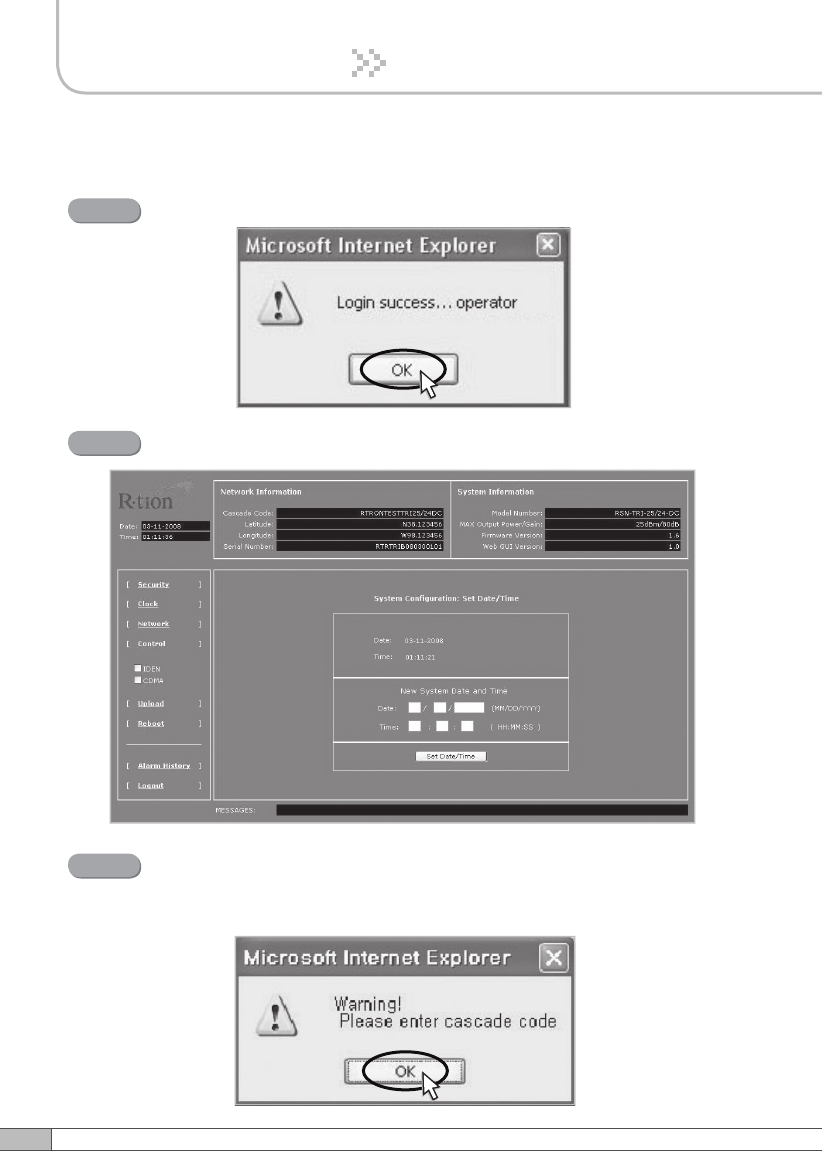
The pop-up message for the login success will appear. Click OK.
Step 3
The login process is complete. The Initial screen will appear.
Step 4
In case of the initial login, you should input Cascade Code and Location
Information of Network Setup. Otherwise a warning pop-up window will
appear and you cannot access any of the menus.
Step 5
33
User’s Manual
4. Operation
Operator has no authorization to access this menu.
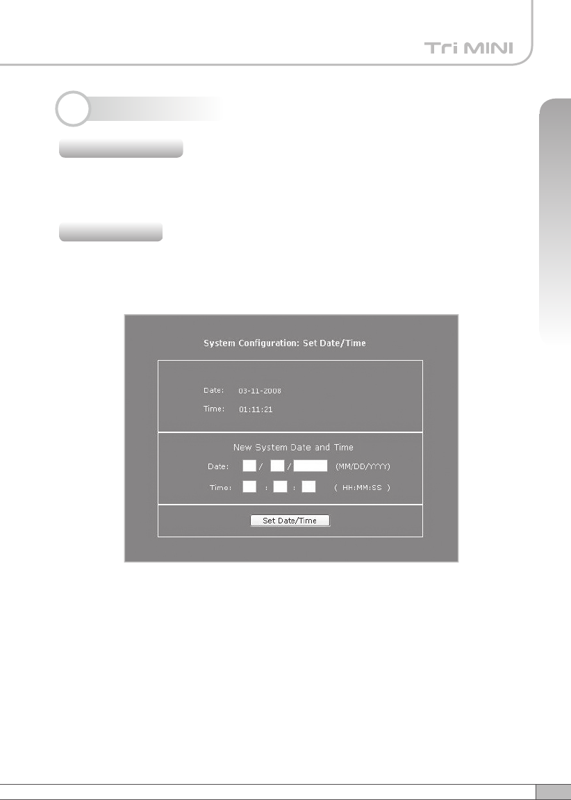
Click Clock in the left menu.
In this menu, you can set the date and the time.
Click Set Date/Time.
4.5 System Setup
4.5.1 Security
4.5.2 Clock
34
4. Operation
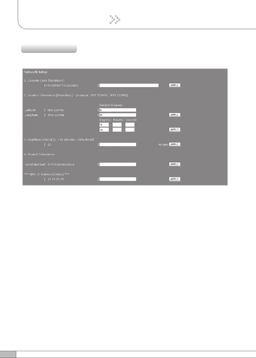
Click Network in the left menu.
4.5.3 Network
Network Setup
•
Cascade Code: Type in the pre-assigned code. Otherwise, you cannot access
system setup.
•
Location Information: Enter the latitude and longitude of a location, otherwise
you cannot access the system setup. You can input either Decimal Degrees or
Degrees-Minutes-Seconds.
[Example.]
(‘N/S ‘ | ‘E/W ‘) ddd.dddddd: (Latitude: N 39.006957 Longitude: W 94.532306)
•
Heartbeat Interval: Sets the time to transmit the Heartbeat to NMC Server.
(Default value is 20 minutes. At the setup, temporarily reduce the value to 1
minute. After conforming heartbeat report, set the value back to 20 minutes.)
•
Product Information: This is for manufacturer used only. DO NOT change this
value.
•
Static IP for Remote Control: Connect to the External Monitoring Device for
Remote Access. Do not enter any value unless a static IP is assigned. DHCP
client.
•
NMC Server IP: Do not change this value; otherwise, the Heartbeat
transmission or Remote Access may not work.
35
User’s Manual
4. Operation
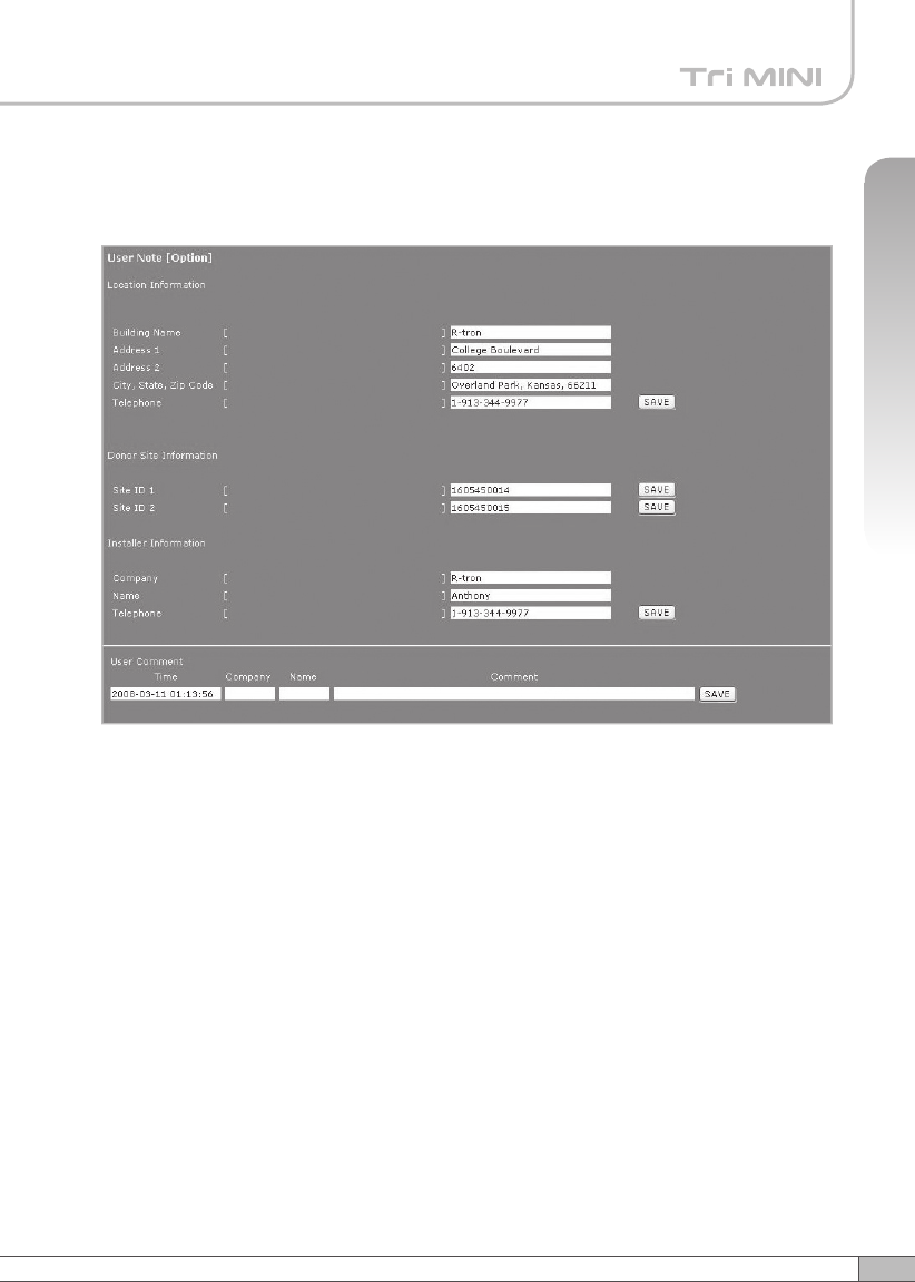
User Note
• Location Information: Type the location information such as the building name,
address, city, state, zip code and telephone, and then click SAVE to save the
information you provide.
• Donor Site Information: Type the base station’s ID, and then click SAVE to save
the information you provide.
• Installer Information: Type the installer information such as the company, name
and telephone, and then click SAVE to save the information you provide.
• User Comment: You can add comments. Up to 50 comments can be stored in the
memory. The length of characters for each comment is limited to 60 characters.
36
4. Operation
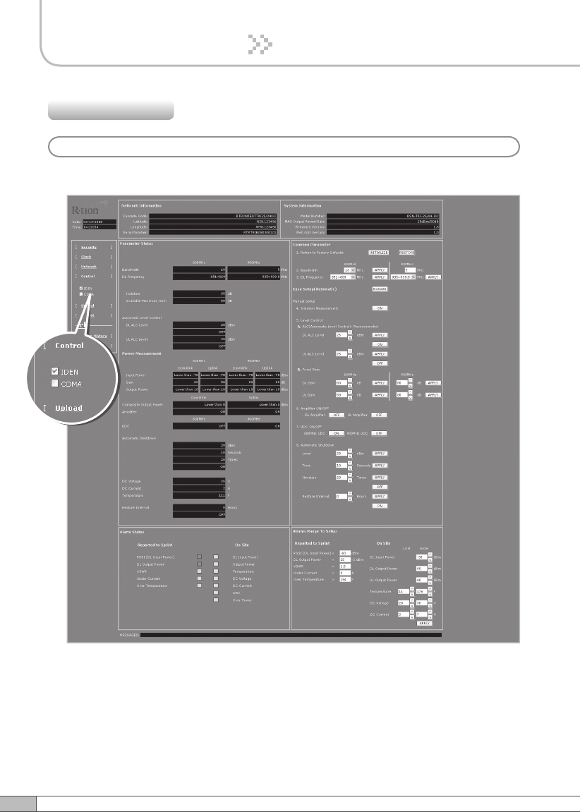
Check IDEN in the left menu.
4.5.4 Control
a. iDEN
37
User’s Manual
4. Operation
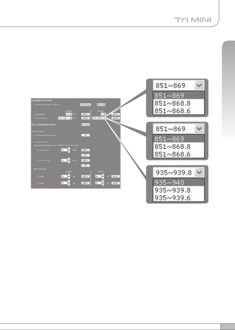
Parameter Setup
• Bandwidth/Frequency:
- For IDEN 800
If you select 18 MHz for bandwidth, the values of the frequency range are
851~869, 851~868.8, 851~868.6.
If you select 7 MHz for bandwidth, the values of the frequency range is
862~869, 862~868.8, 862~868.6.
- For IDEN 900
The values of the frequency range is 935~940, 935~939.8, 935~939.6.
38
4. Operation
Solution 1. Easy Setup [Recommended]
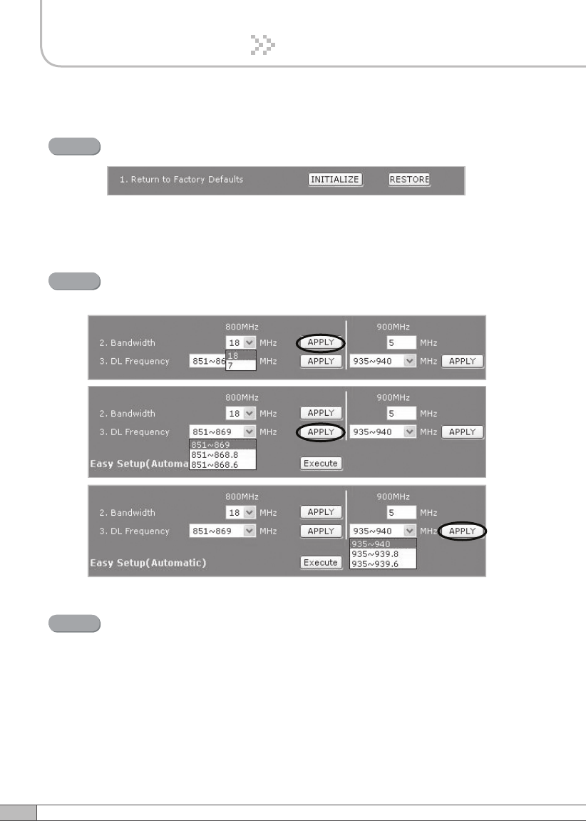
Return to Factory Defaults
Step 1
• To reset factory defaults, click INITIALIZE.
• To restore the previous settings, click RESTORE.
Step 2 Select the operating bandwidth and operating frequencies
(5MHz-bandwidth fixed in iDEN 900) and click APPLY.
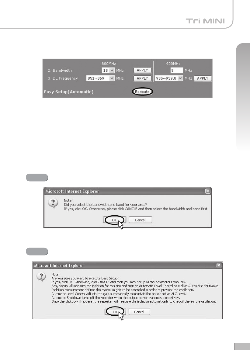
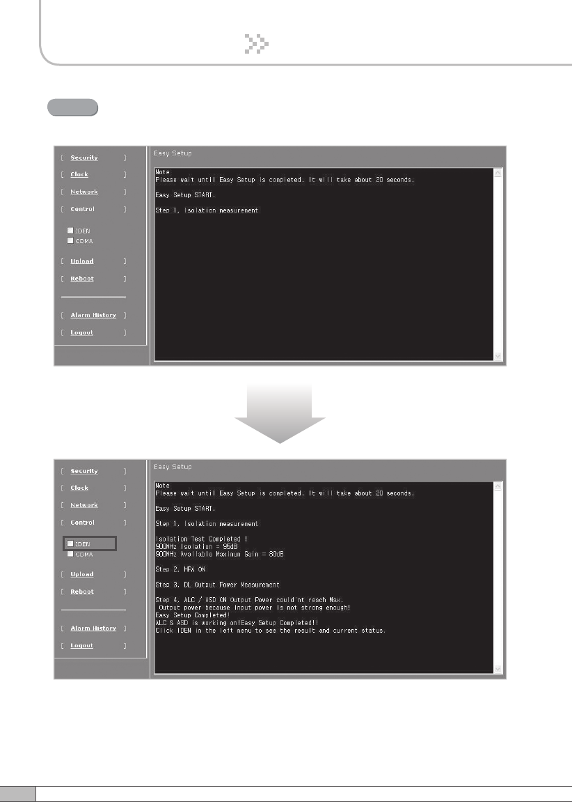
Easy Setup
Step 3
Easy Setup proceeds to:
• Isolation measurement On
• Calculation of Available Maximum Gain by the isolation.
• ASD On
• ALC On to get Maximum DL Output Power 25dBm [Defaults] or
Maximum Gain 80dB. Click Execute.
39
User’s Manual
4. Operation
Easy setup feature will measure the isolation and limit the maximum
gain accordingly. This will also enable Auto Level Control as well as Auto
Shut Down. These two features are strongly recommended to prevent
the uncontrolled power output, which could have an adverse impact
on the RF network and the repeater. For example, ALC will apply
attenuation automatically when the input signal strength is increased due
to the new base station deployment near the repeater site.
Click OK.
Step 4
Click OK again.
Step 5
41
User’s Manual
40
4. Operation
4. Operation
Setup will automatically begin. This process will take approximately
20seconds.
Step 6
10~20 seconds
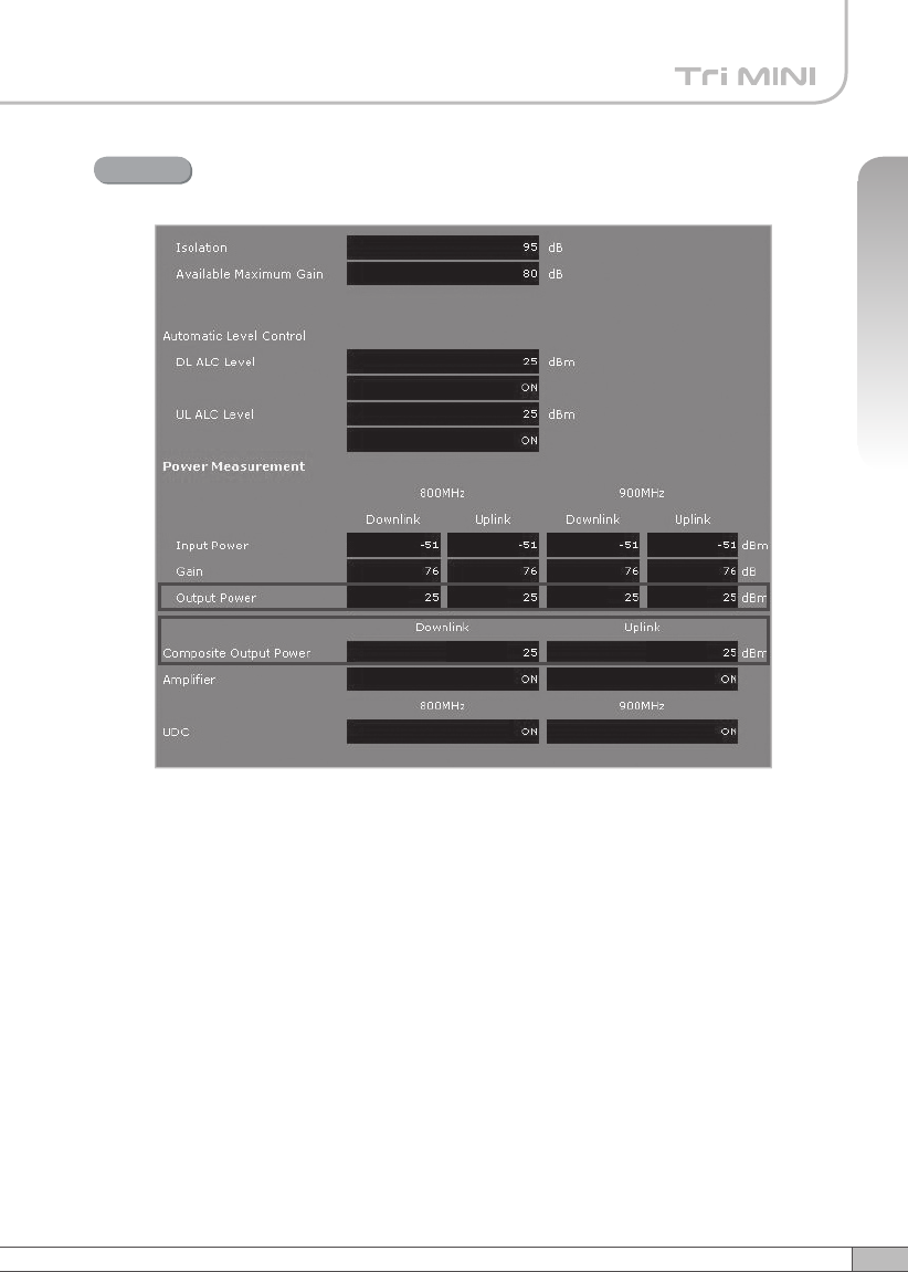
Click IDEN in the left menu.
41
User’s Manual
40
4. Operation
4. Operation
Constant Maximum DL Output Power 25dBm
if the DL Input Power ≥-55dBm.
Result 1
42
4. Operation
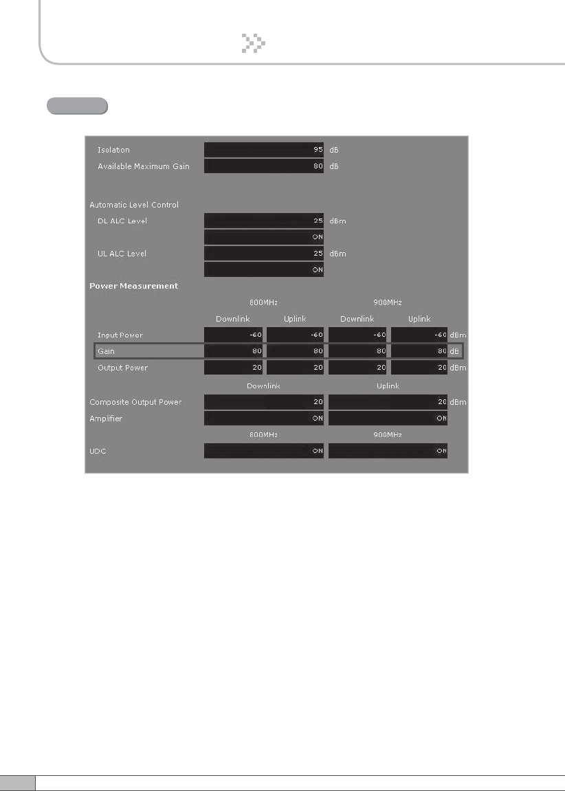
Maximum Gain 80dB if the DL Input Power <-55dBm.
Result 2
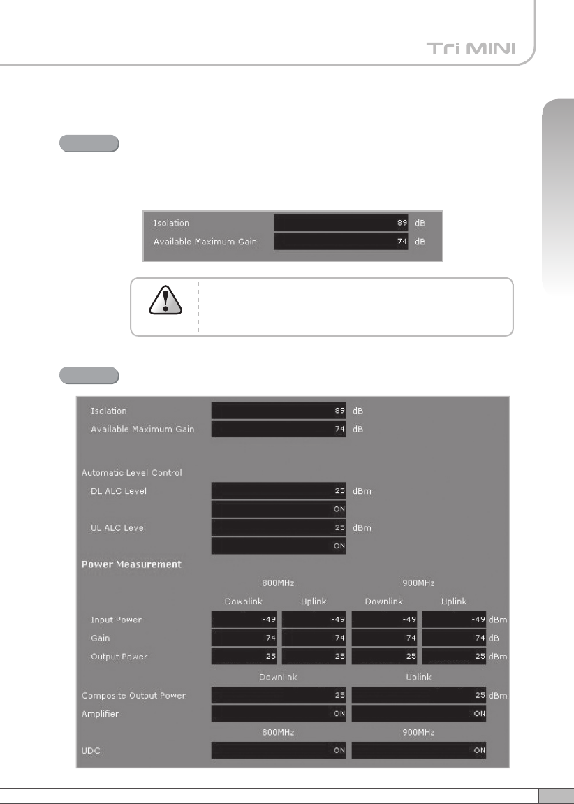
After running Easy Setup or Isolation Measurement, Isolation is displayed with “95”
when the isolation is higher than 95dB, or it is displayed with the actual when the
isolation is lower than 95dB.
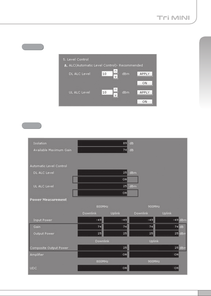
•Automatic Level Control: Type under 25 and then click APPLY and ON.
[Example]
For the repeater with 25dBm maximum output power, 80dB maximum gain /
30dB gain control range, → If the signal -45dBm and the ALC is set as 25dBm
the gain will be 70dB to adjust to the output power.
If the input signal is -60dBm, the output power will be 20dBm by the limitation of
the maximum gain even though the ALC is set as 25dBm.
43
User’s Manual
4. Operation
• Automatic Shutdown: Type the desired values for dBm, seconds, and times
and then click APPLY and ON.(e.g. 28dBm, 3seconds, 10times)
[Example]
For the repeater with 25dBm Maximum Output Power, 80dB Maximum
Gain / 30dB gain control range, Assuming ASD Level: 28dBm, ASD Time:
3seconds, ASD Iteration: 10.
If the output power is 28dBm(ASD LEVEL) and higher, the repeater will
shutdown for 3 seconds(ASD TIME). If the shutdown occurs 10 times (ASD
COUNT), the 10th shutdown will be permanent.
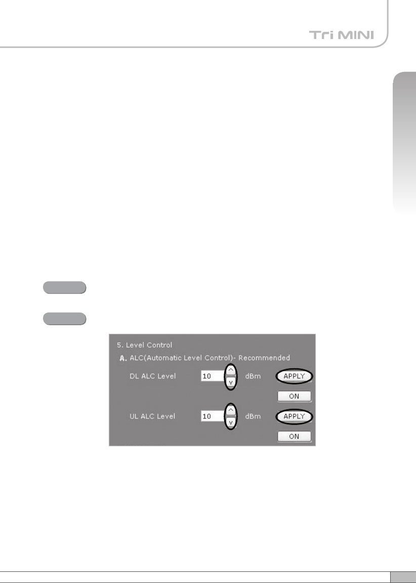
Solution 2. DL Output Power < Max. 25dBm
Repeater Step 1 through Step 6.
Step 2A
Step 1A
Change the level at Automatic Level Control and click APPLY.

44
4. Operation
Constant output power set as the ALC level.
Result
45
User’s Manual
4. Operation
Solution 3. Fixed Gain [Not Recommended]
Repeat Step 1 through Step 6.
Easy Setup will calculate the Available Maximum Gain which defines
the maximum gain to be setup.
Step 1B
Read DL Input Power and the gain controlled by Easy Setup.
Step 2B
DO NOT setup the gain higher than the Available
Maximum Gain.
Warning
47
User’s Manual
46
4. Operation
4. Operation
Turn off DL Amplifier and UL Amplifier.
Step 3B
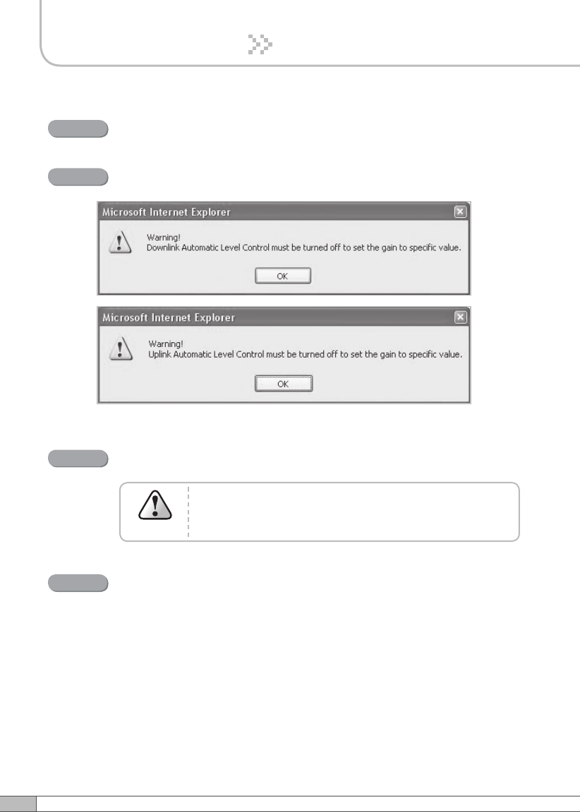
ALC must be turned off, otherwise, the following message appears.
Step 4B
The gain must be lower than the current value and
Available Maximum Gain.
Warning
Change DL Gain and UL Gain.
Step 5B
Turn on DL Amplifier and UL Amplifier.
Step 6B
47
User’s Manual
46
4. Operation
4. Operation
Turn on the ALC.
Step 7B
DL and UL gain fixed and the output power depends on the input
power.
Result